
Review on Study Methods for Reciprocally Enwrapping Surfaces

 , , ,
, , , 
Abstract
:1. Introduction
2. Materials and Methods
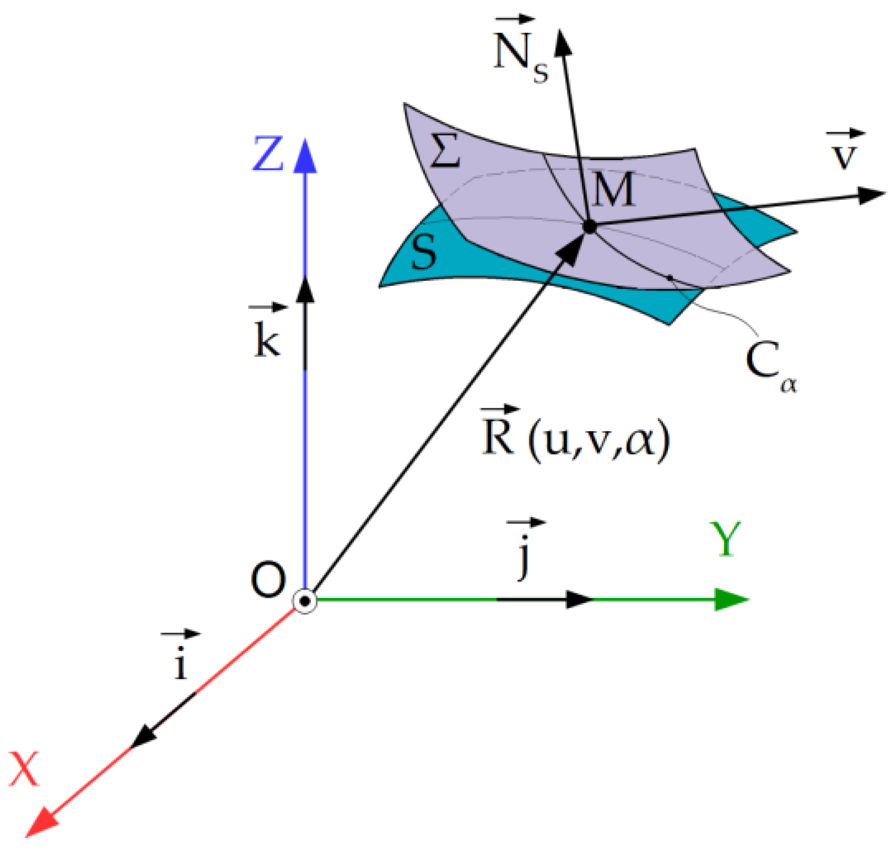
2.1. Olivier Method
- -
- -
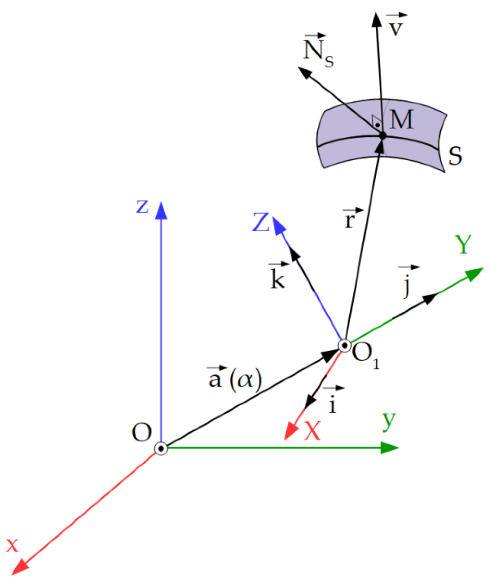
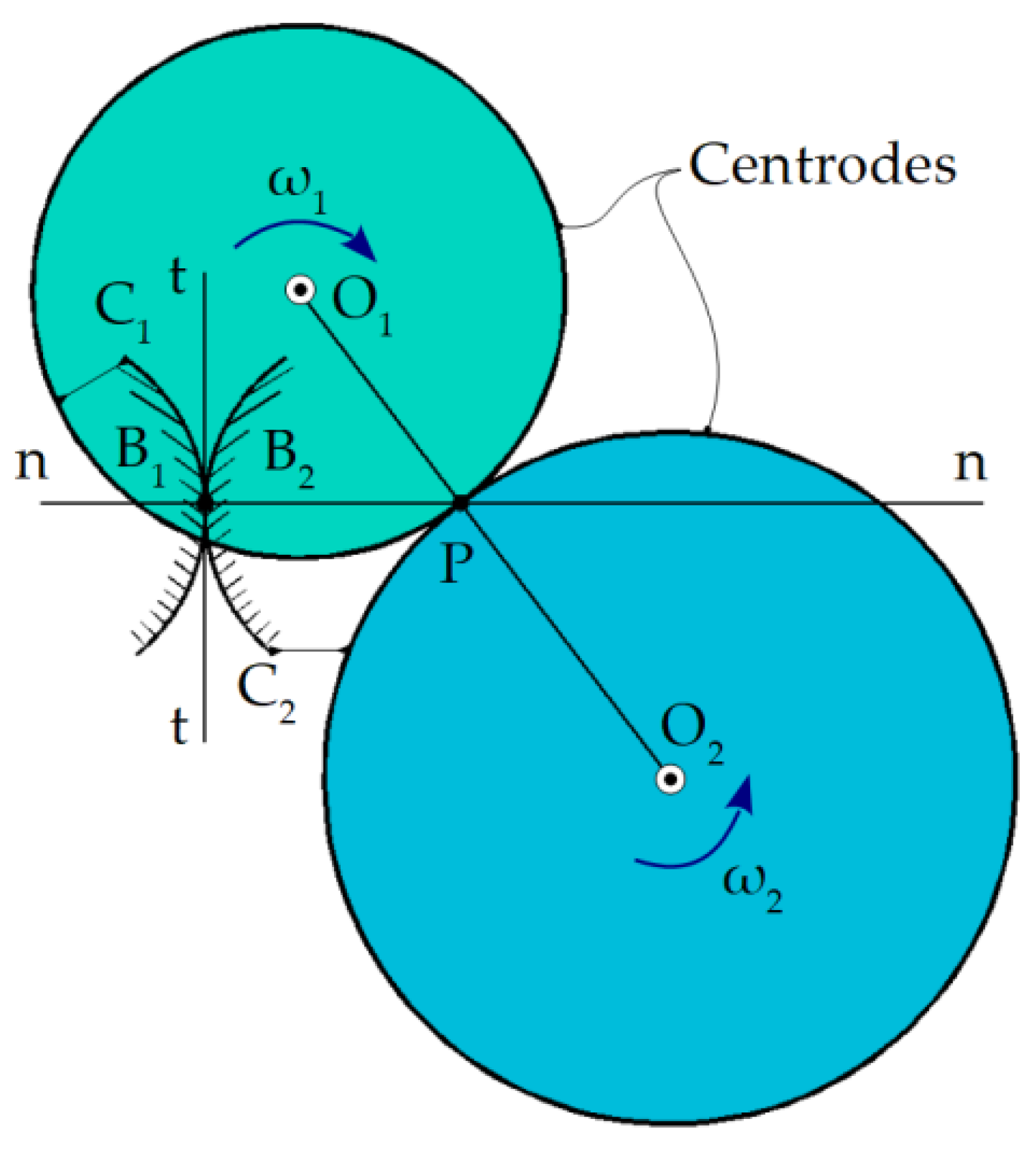
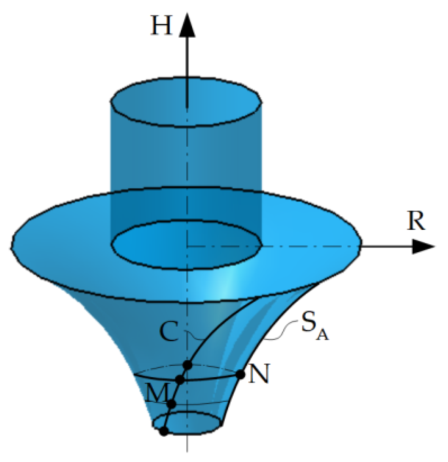
2.2. Gohman Theorem
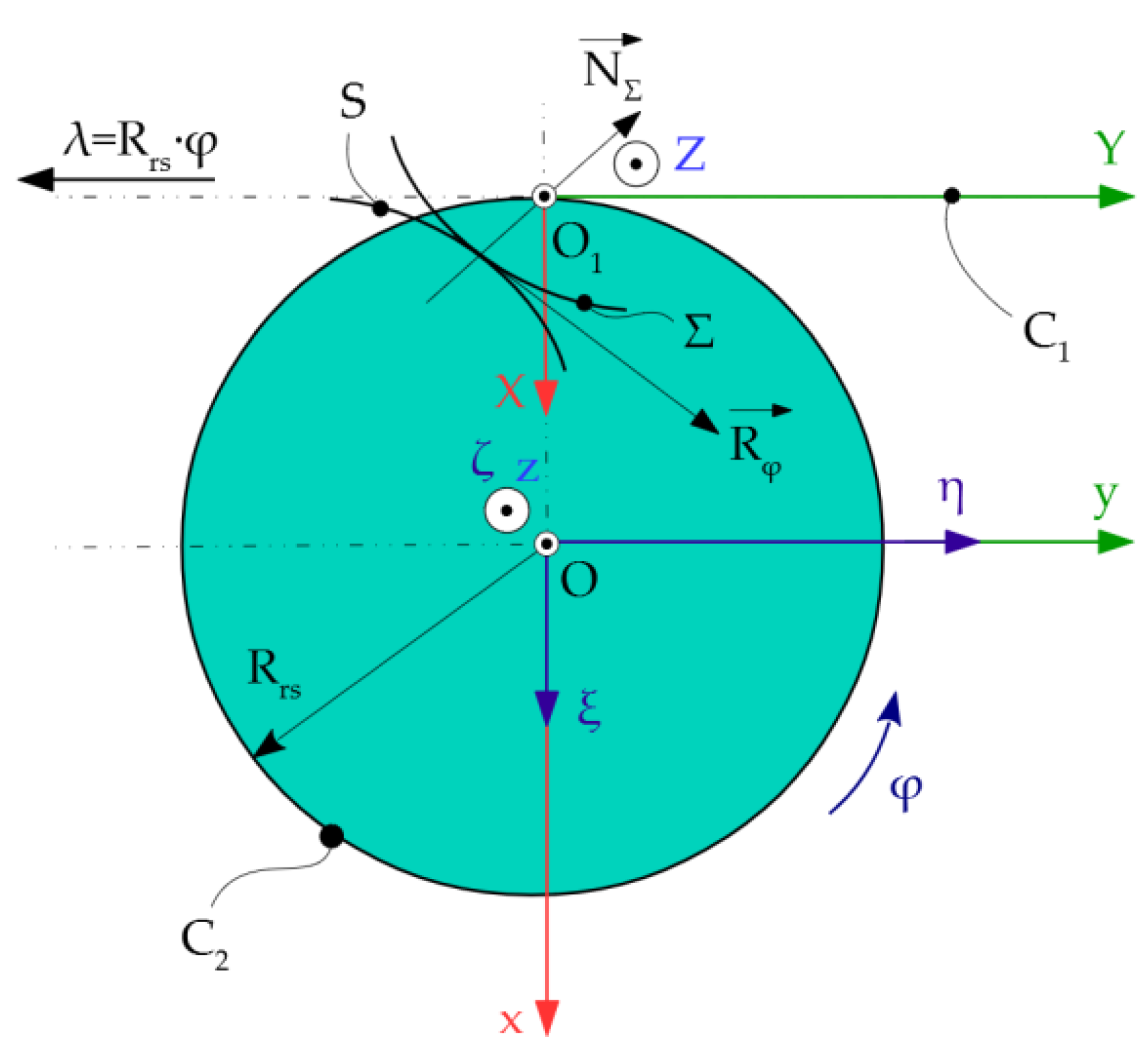
2.3. Normals Method (Willis Theorem)
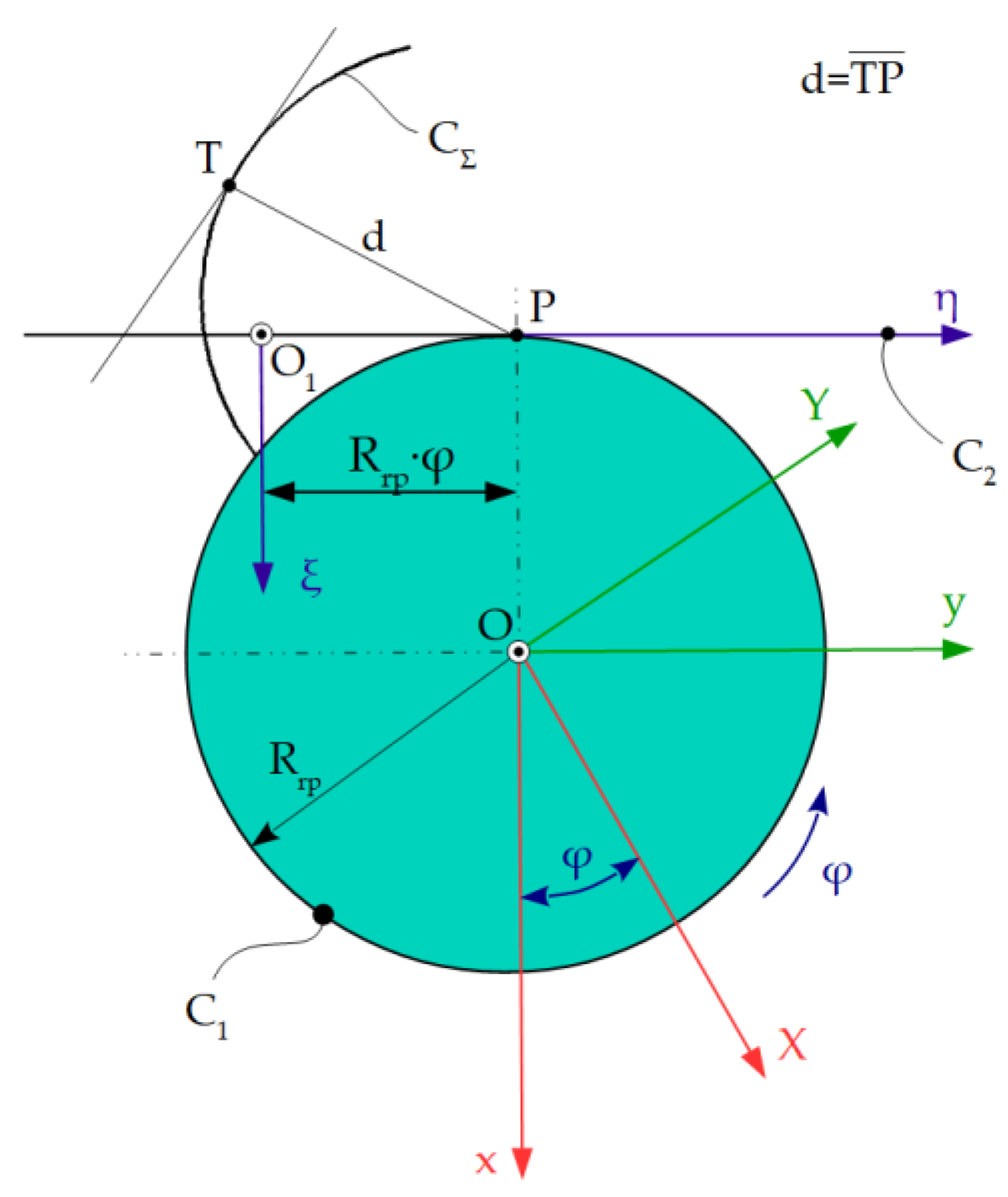
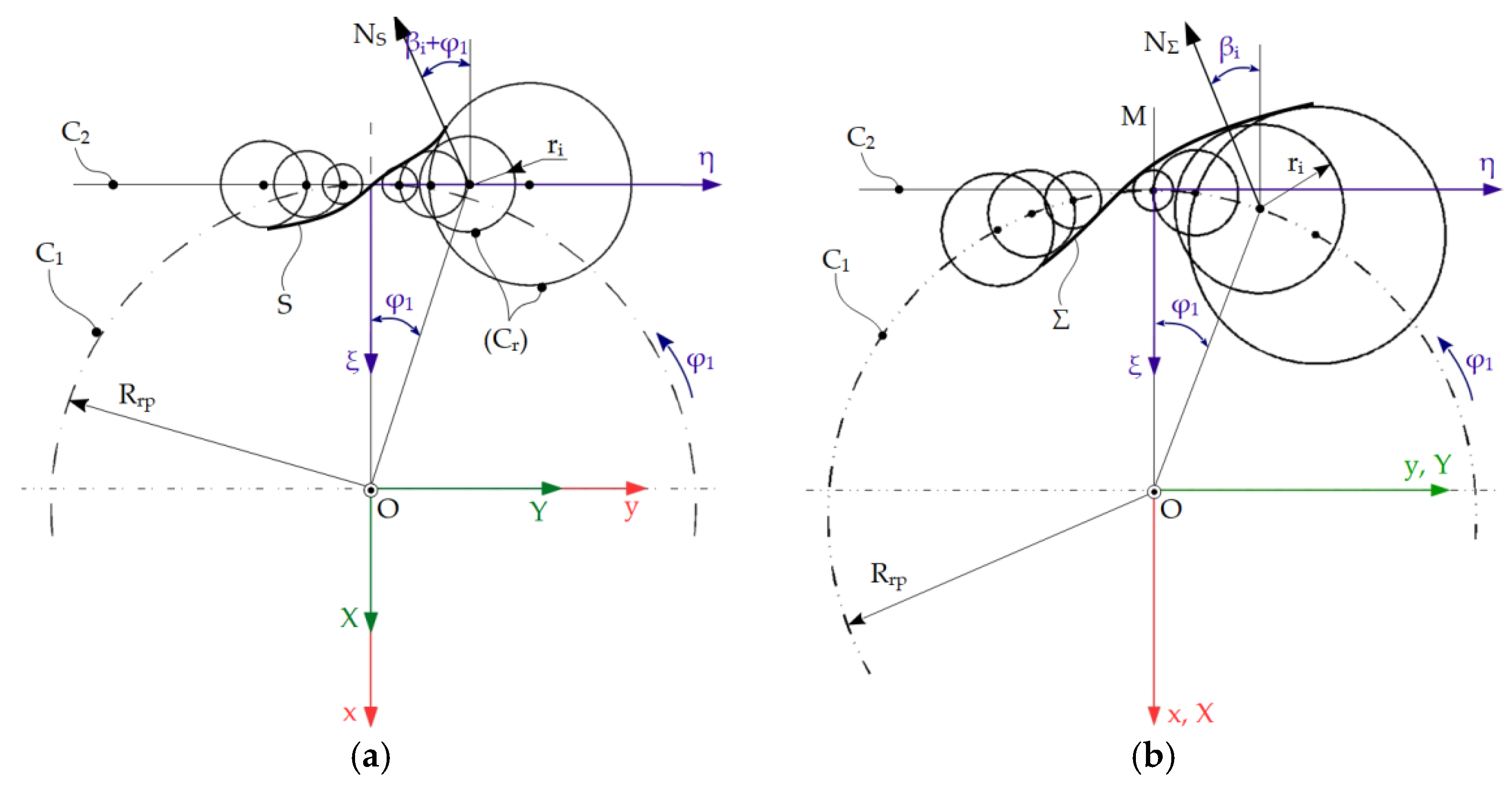
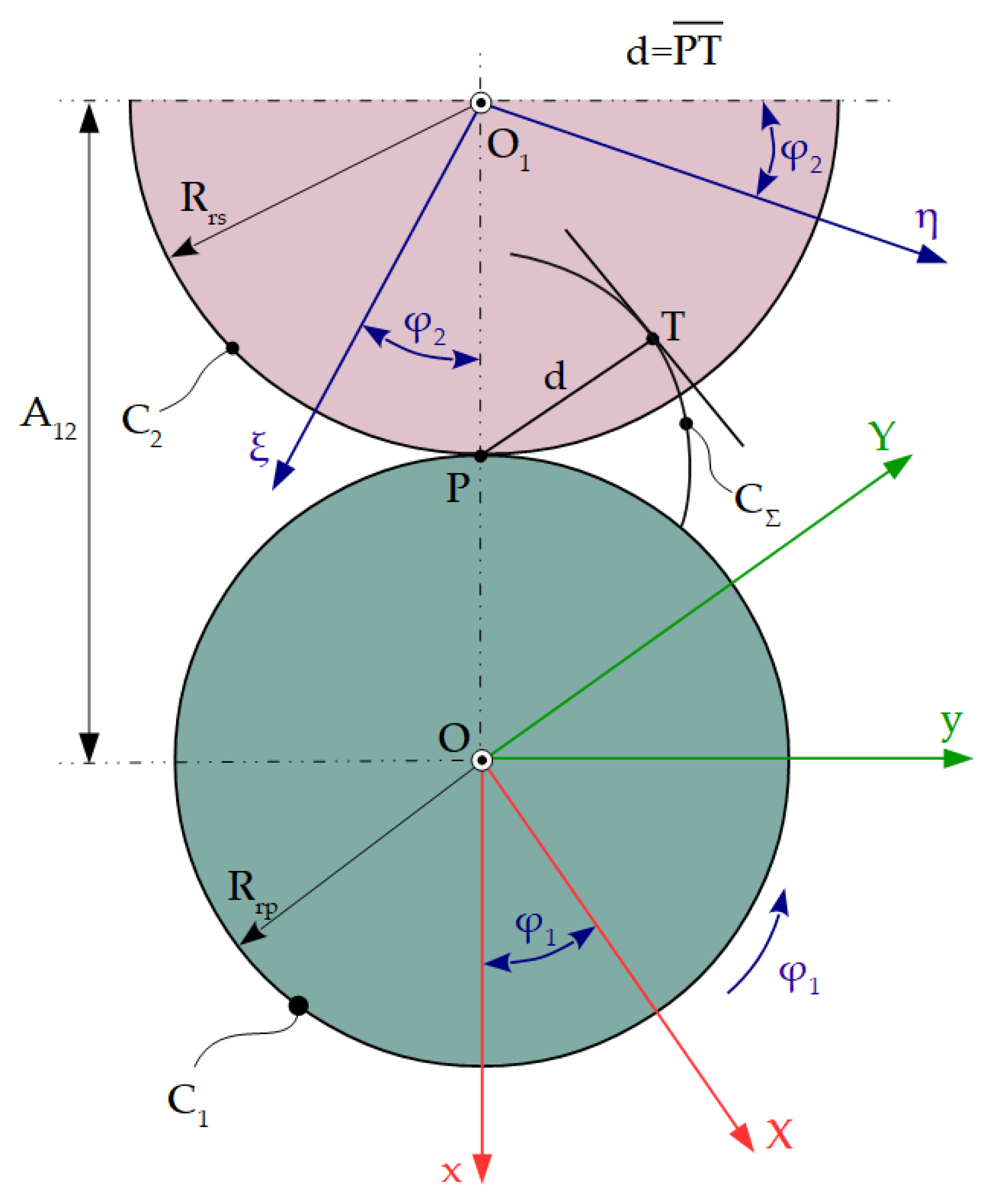
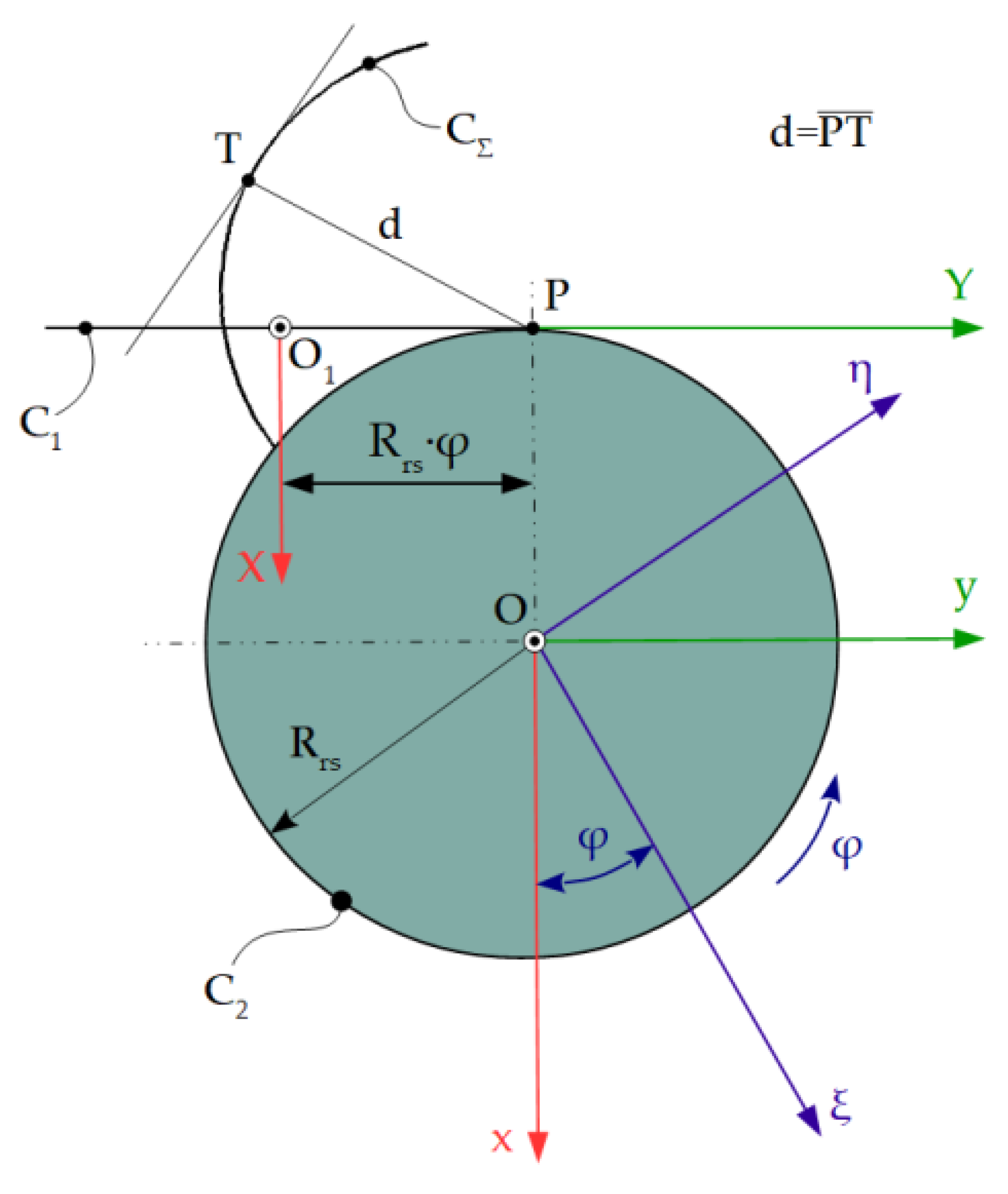
2.4. Minimum Distance Method
- -
- Centrode associated with the vortex of the blank profiles—C1 (radius circle Rrp);
- -
- Centrode associated with the flank of the generating rack—C2 (line superimposed on the η axis);
- -
- Reference systems: xy—fixed reference system; XY—mobile reference system, joined with the blank; and ξη—mobile reference system, joined with the generating rack.
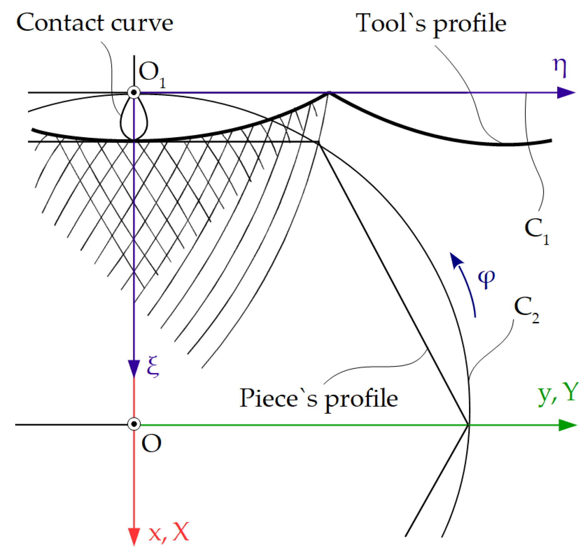
2.5. Method of Substituting Circles
2.6. Trajectory Method
2.7. Comparative Study on Specific Forms of Enwrapping Condition
- (1)
- Establishing the parametric equations of the profile to be generated;
- (2)
- Determining the form of the rolling condition, which determines that the lengths traversed by the instantaneous centers of rotation, on each of the two centrodes, are equal;
- (3)
- Determining the absolute movements of the piece and the tool;
- (4)
- Based on the absolute movements, the relative movements between the tool and the piece are determined;
- (5)
- Considering the fixed tool, the family of curves generated by the profile of the piece is determined, during the relative movement that it has towards the tool;
- (6)
- Determining the specific form of the enwrapping condition;
- (7)
- Associating to the family of curves, determined in step 5, the enwrapping condition obtained in step 6, the profile of the generating tool is determined; practically, the enwrapping condition allows that, from the points belonging to the family of curves, only those belonging to the envelope, and, therefore, to the tool profile, to be selected.
- (8)
- The parametric equations of the gearing curve can be obtained; this represents the geometric locus, in the fixed space, in which the tangency between the two reciprocally enveloping profiles takes place, that of the piece-known and that of the tool-determined.
2.7.1. Rack Tool Profiling—Gohman’s Theorem
2.7.2. Gear Shaped Cutter Tools Profiling—Gohman’s Theorem
2.7.3. Rotary Cutter Tools Profiling—Gohman’s Theorem
2.7.4. Rack Tool Profiling—Minimum Distance Method
2.7.5. Gear Shaped Cutter Tool Profiling—Minimum Distance Method
2.7.6. Rotary Cutter Tool Profiling—Minimum Distance Method
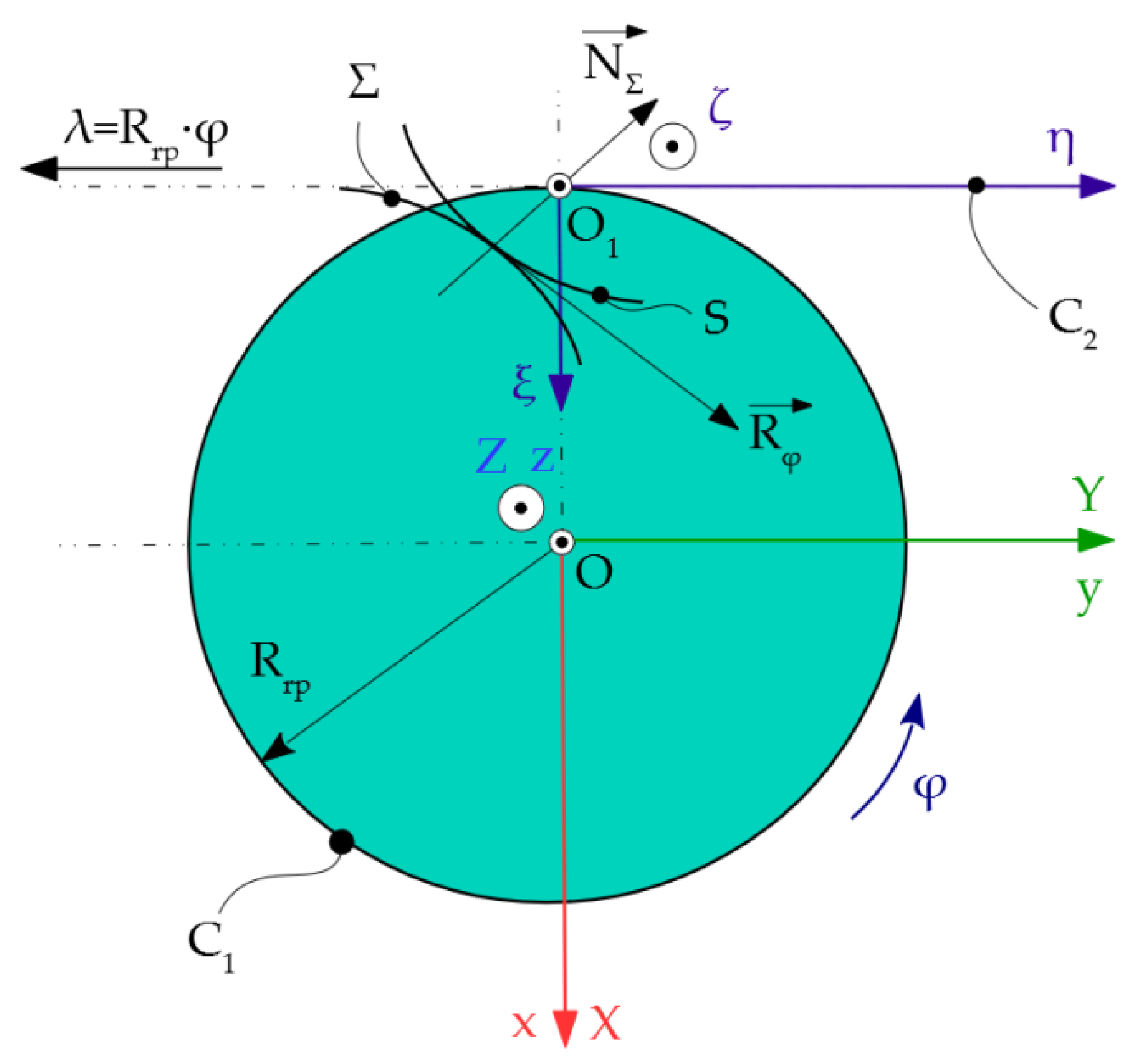
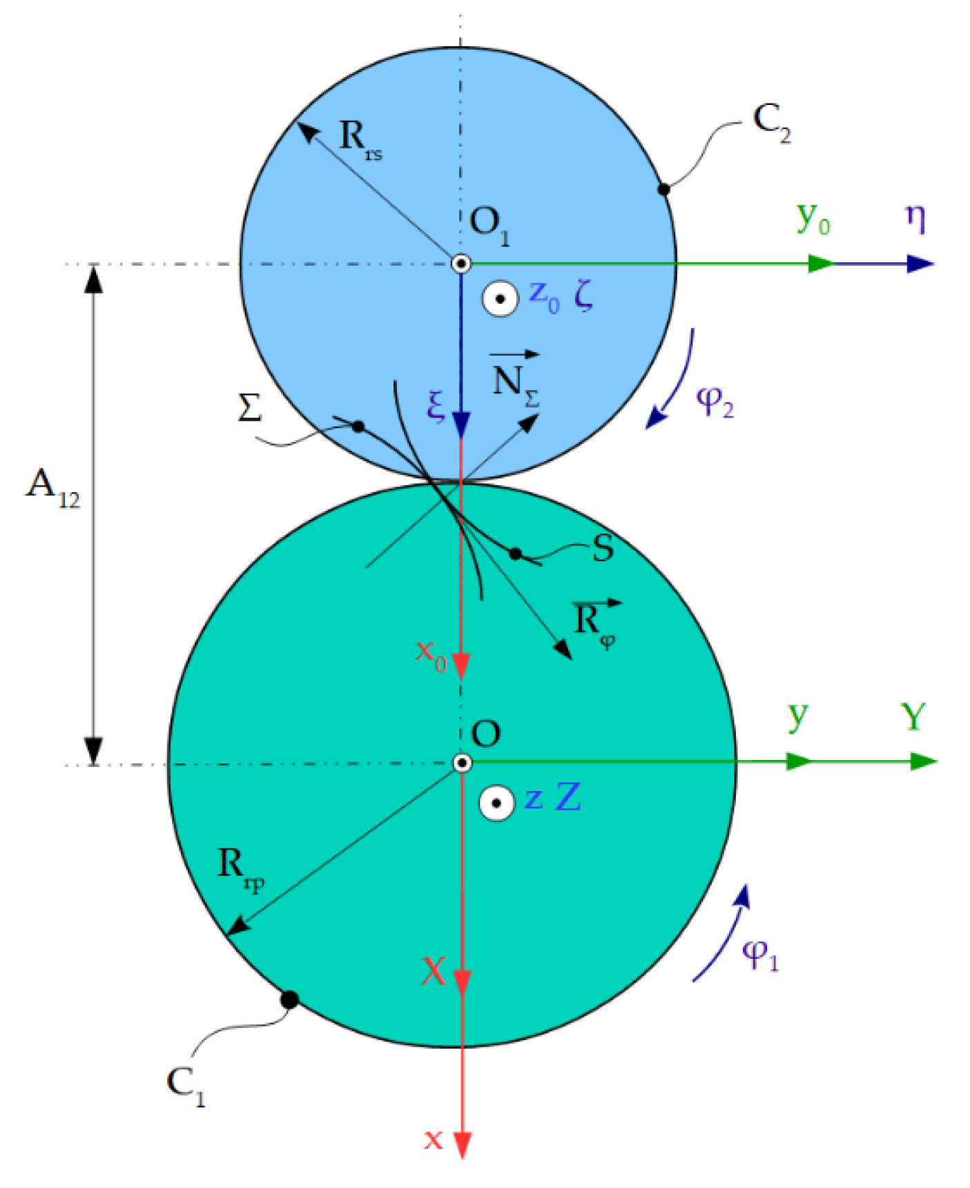
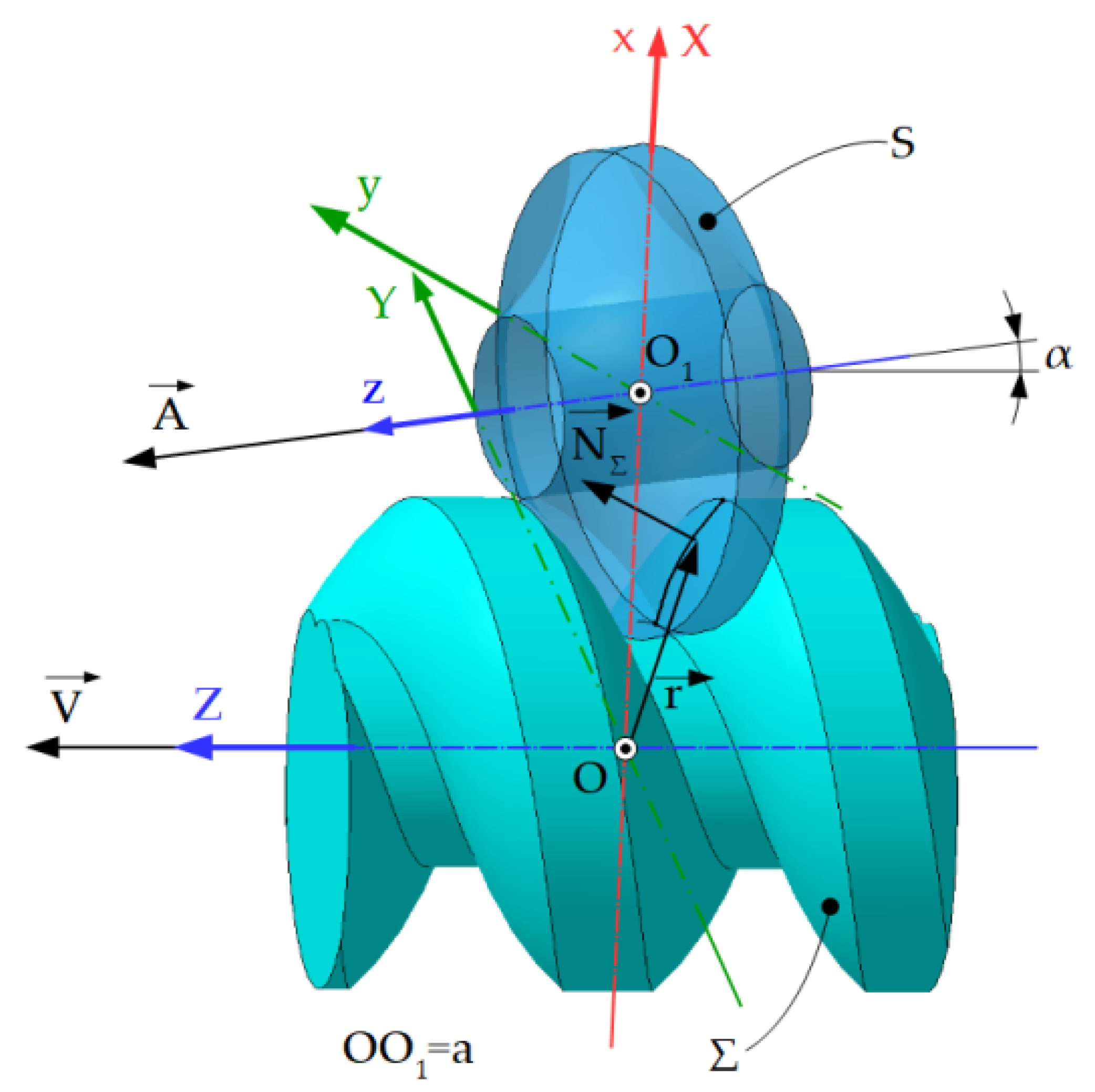
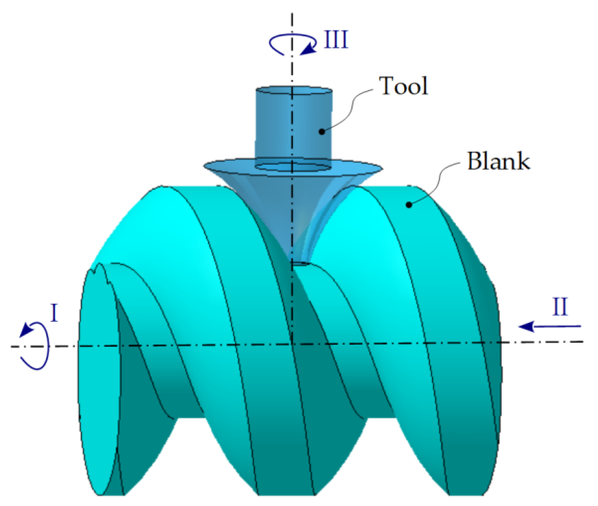
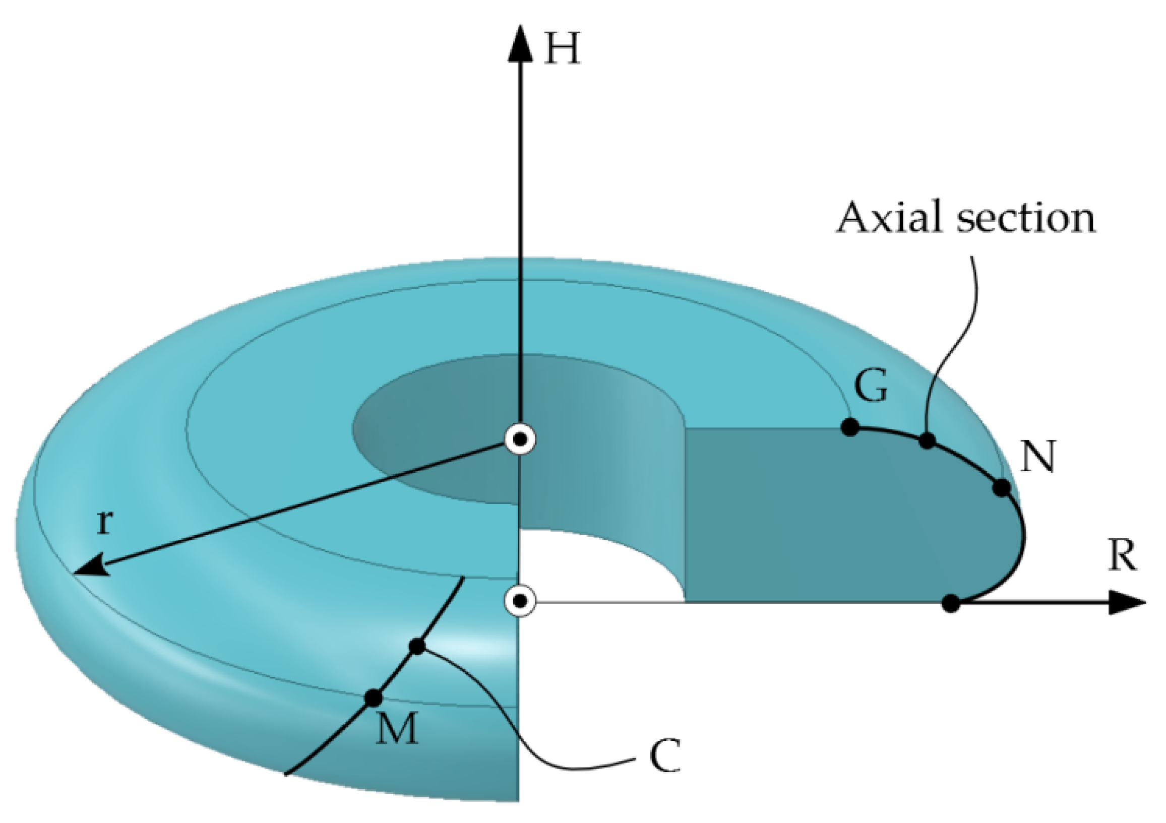
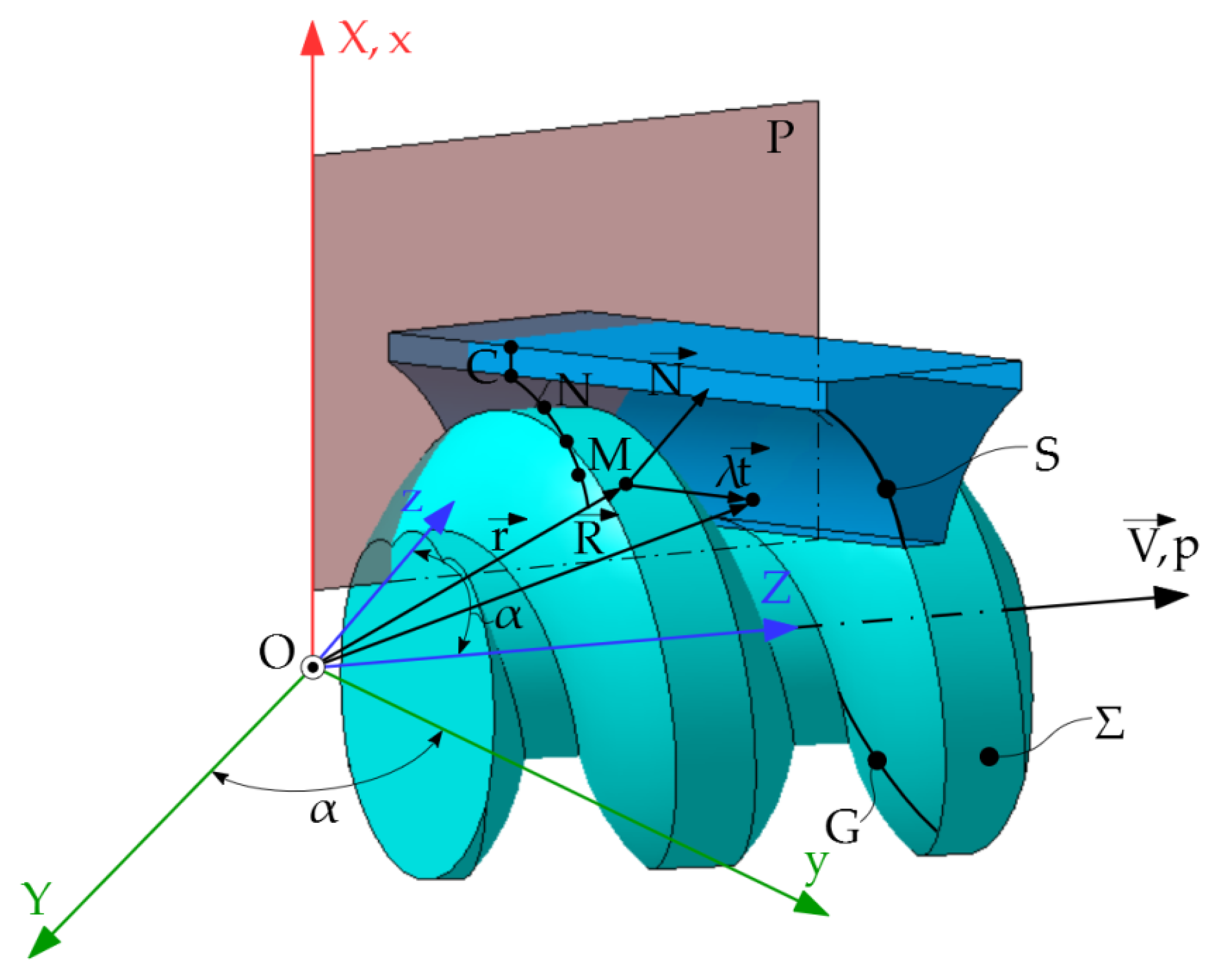
2.8. Profile of Tools for Generating of Helical Surfaces by Kinematic Method
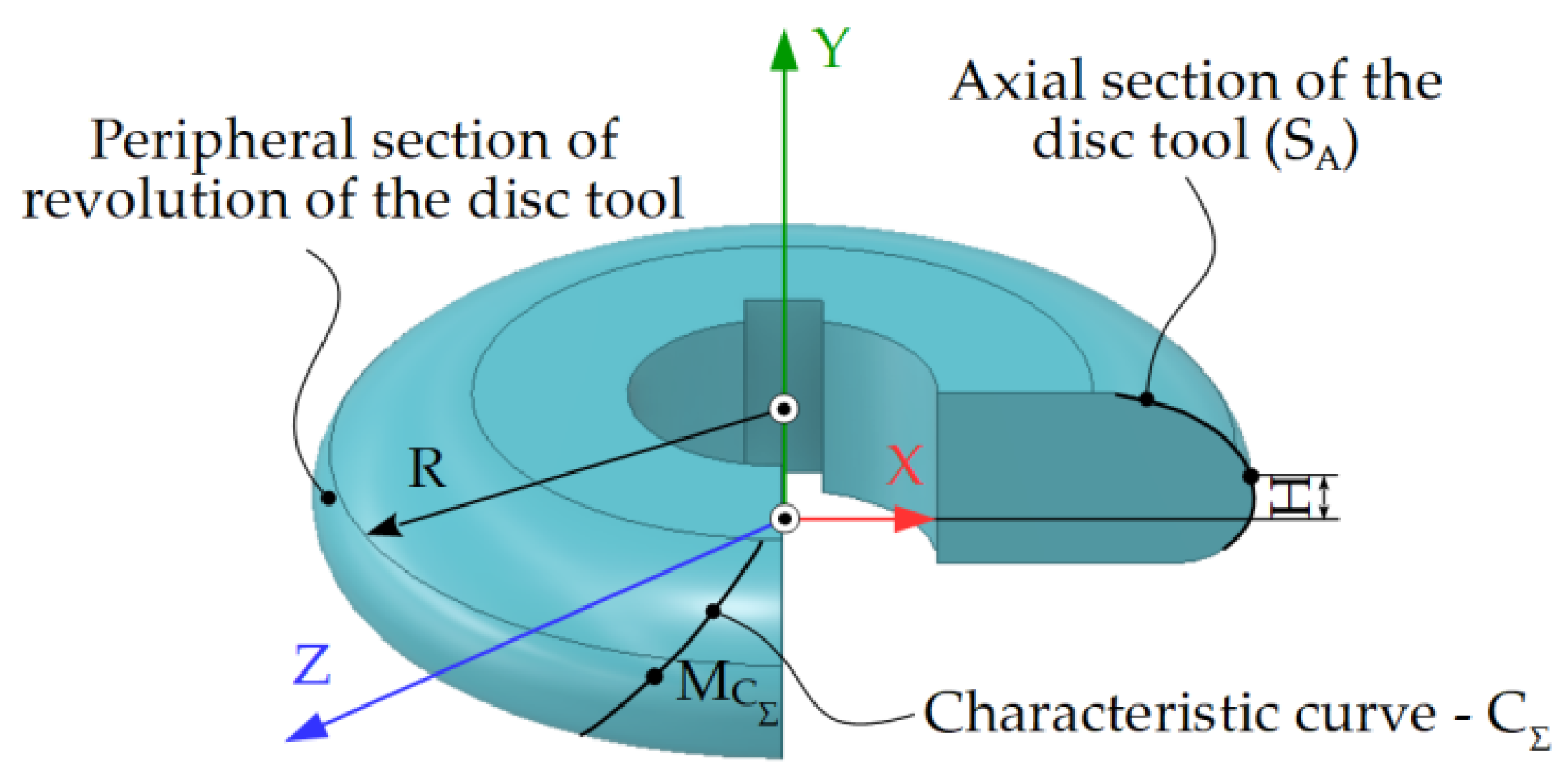
2.8.1. Profiling of the Disk Tool for the Generating of Helical Surfaces—Profiling Algorithm
- -
- α represents the transformation matrix between the versors of the XYZ and xyz systems and is given by the relation:
- -
- A-the matrix formed by the coordinates of point O1, compared to the fixed coordinate system.
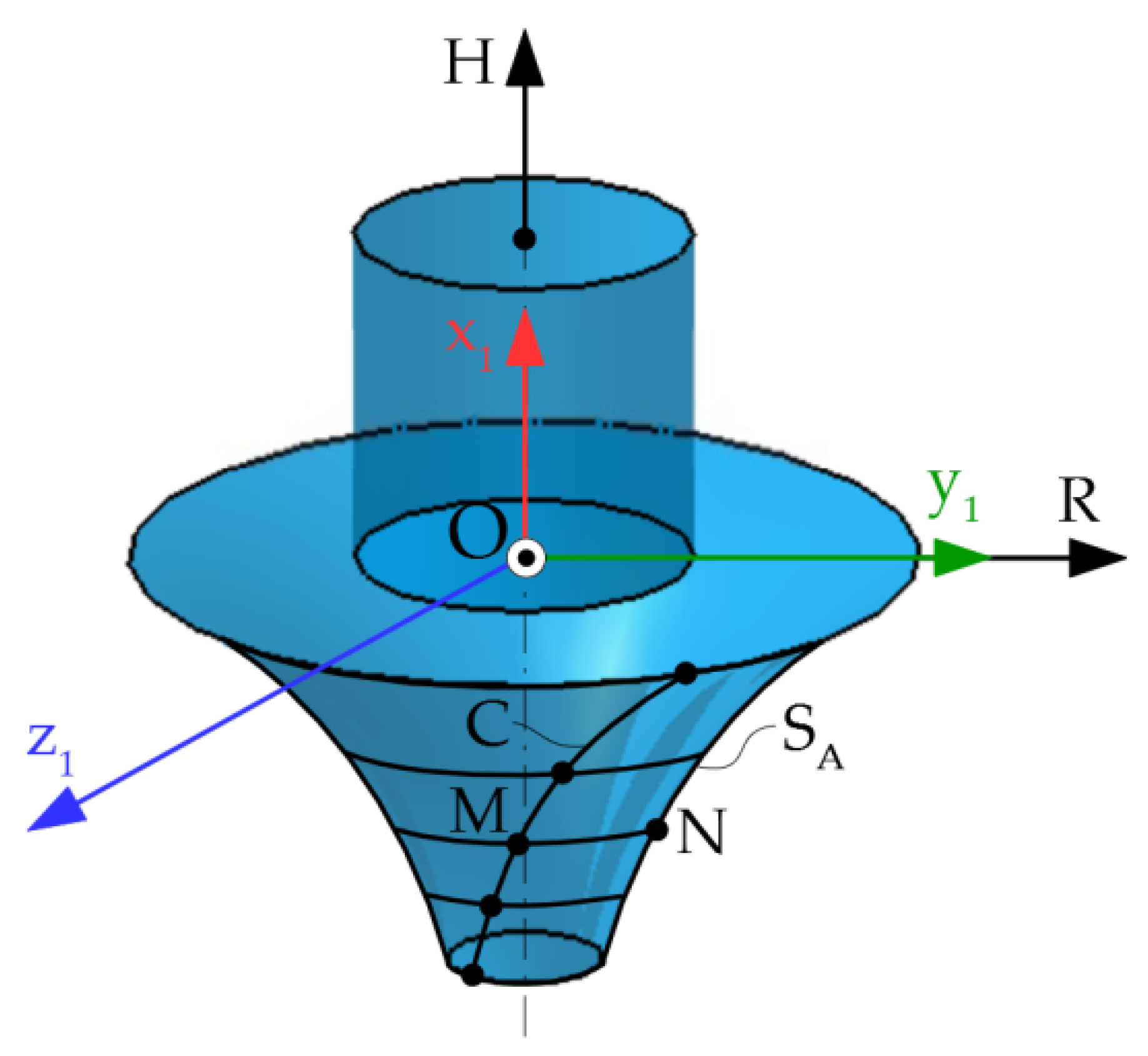
2.8.2. Profiling of Cylindrical-Front Tools (Finger Cutter Tools) for the Generating of Helical Surfaces—Profiling Algorithm
2.8.3. Profiling of Cylindrical Generating Tools (Slotting Tools) for Generating of Helical Surfaces—Profiling Algorithm
- -
- Translational movement, along the own generators, determining the main cutting movement;
- -
- Helical movement of the axis and helical parameter p, determining the generating movement of Σ surface.
- -
- represents the vector of a current point on the cylindrical surface;
- -
- —the vector of a current point on the characteristic curve;
- -
- λ—variable parameter;
- -
- —the versor of the cylindrical surface generators.
2.9. Generating of Helical Surfaces by the Method of Decomposing the Helical Movement—Nikolaev Condition
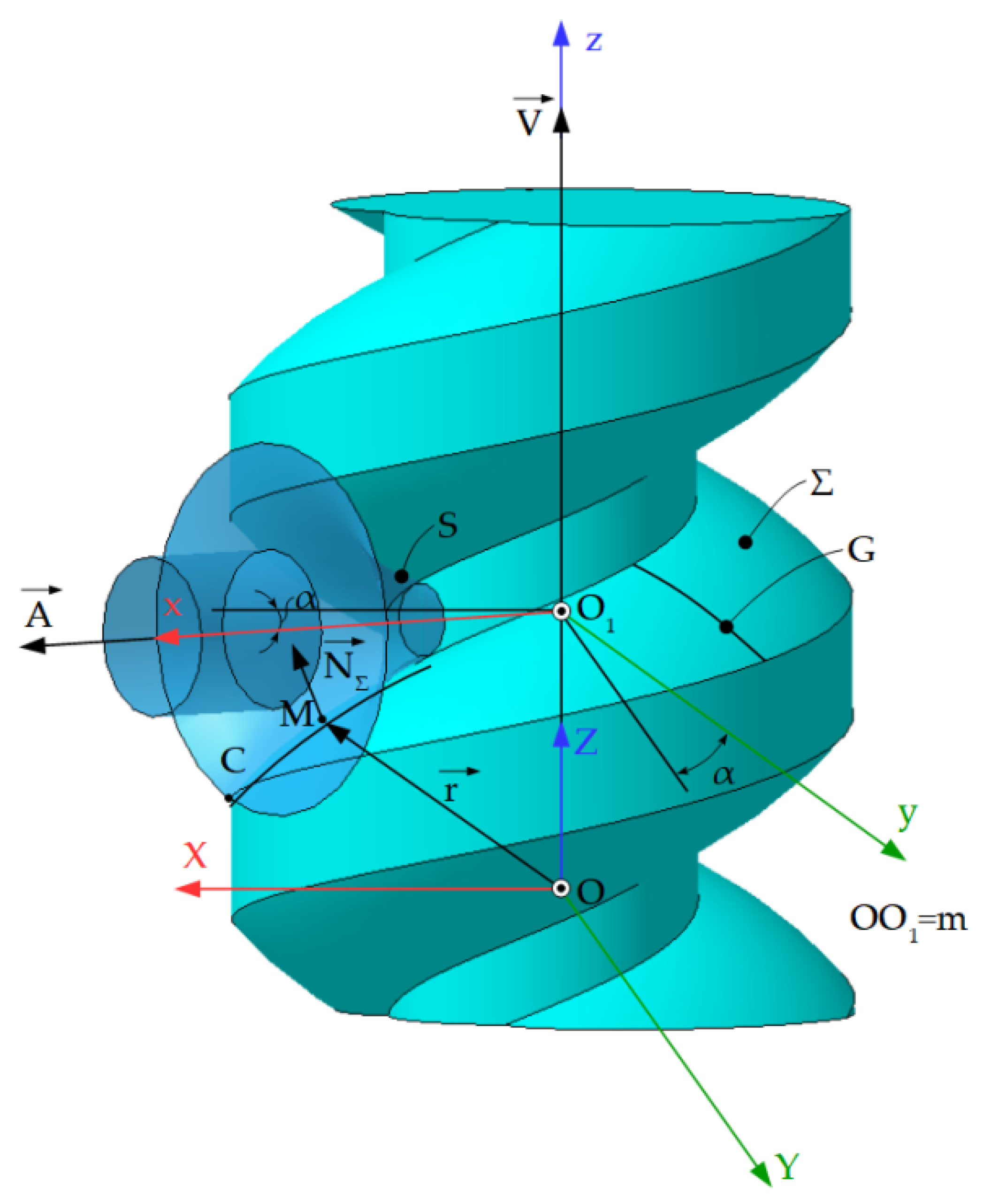
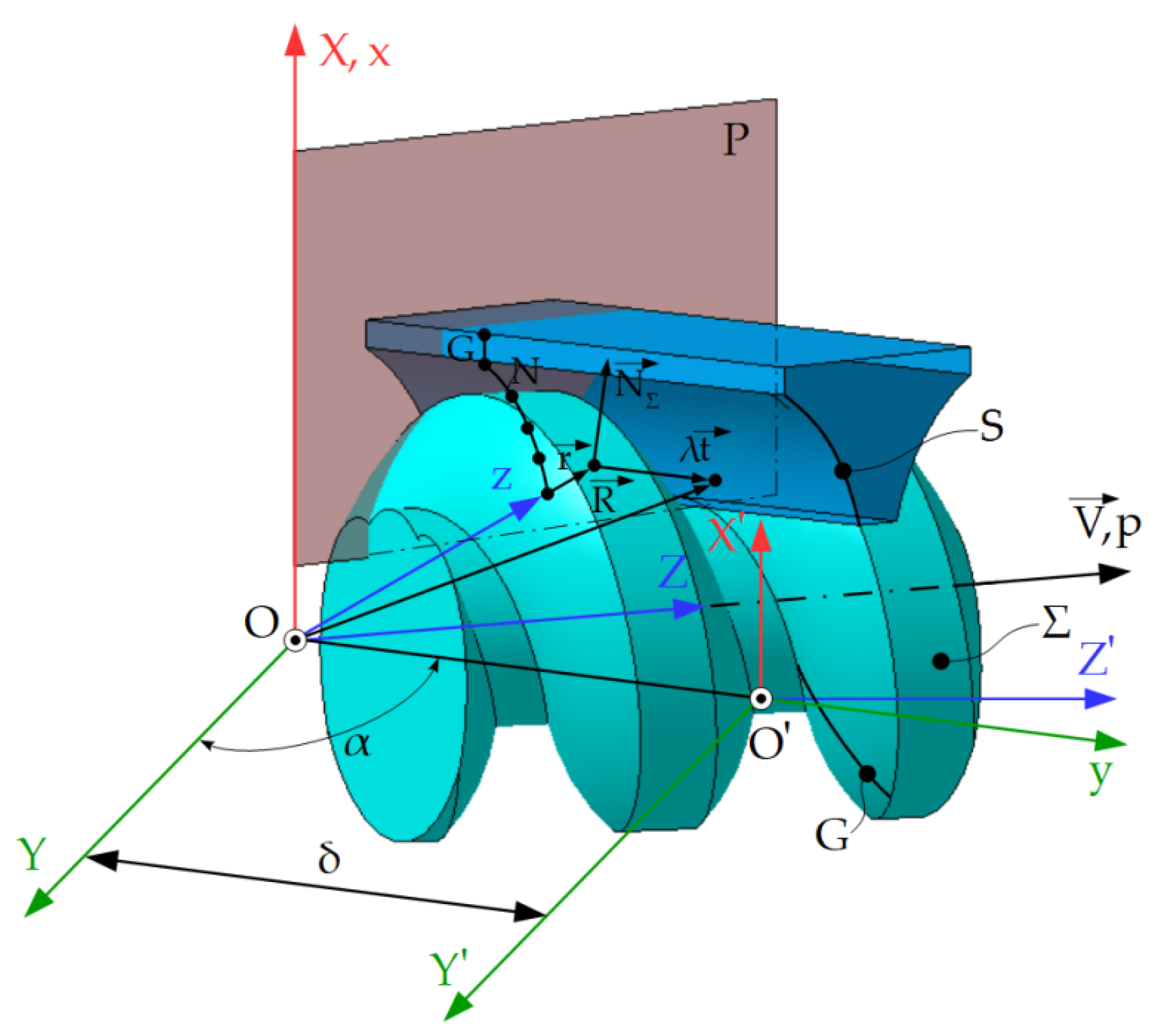
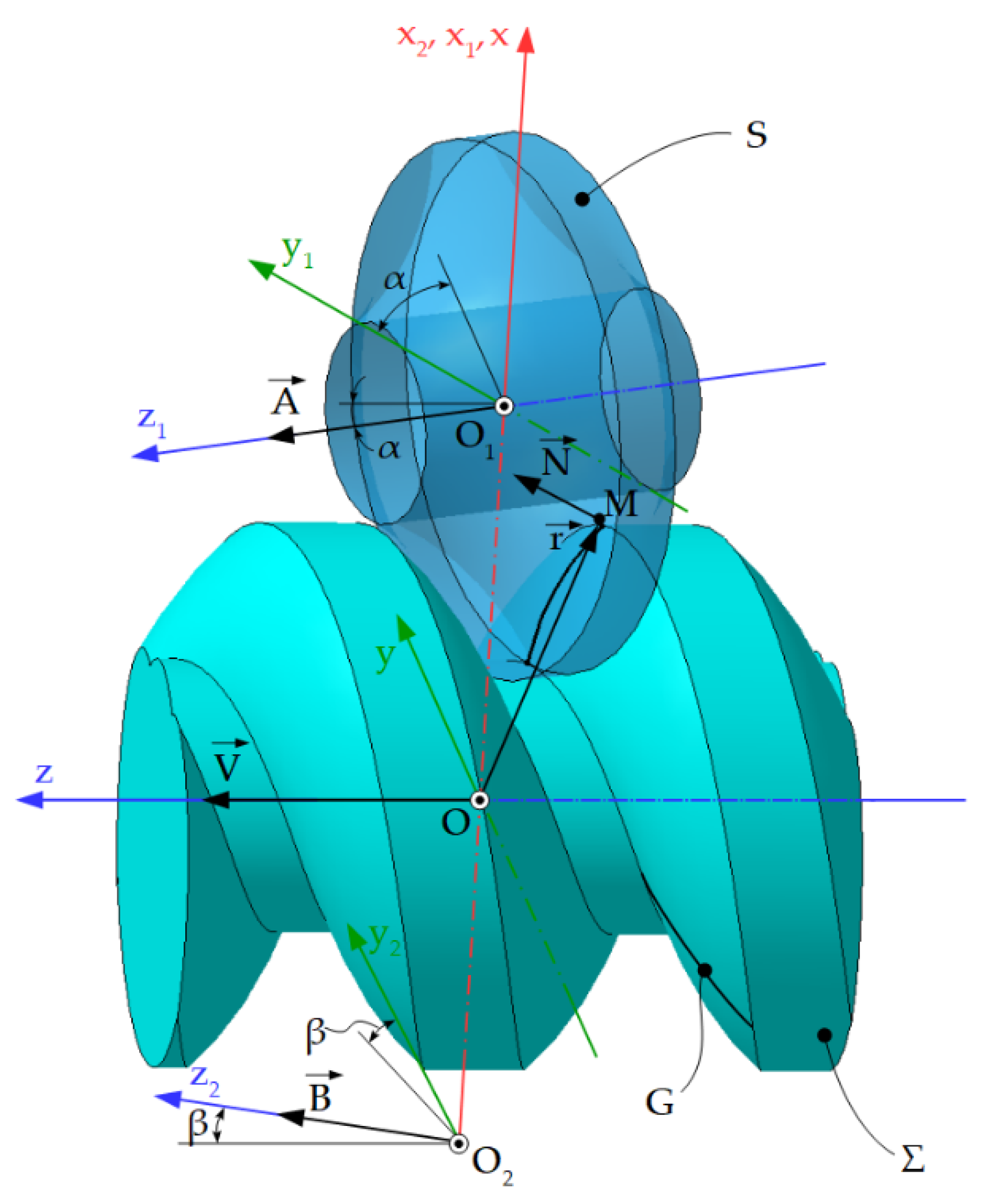
2.9.1. Generating of Helical Surfaces with Disc Tools—Profiling Algorithm
- -
- xyz represents the fixed reference system, the z axis being superimposed on the surface axis Σ;
- -
- x1y1z1—fixed coordinate system with z1 axis being superimposed on the axis
- -
- x2y2z2—fixed coordinate system, z2 axis being superimposed on the axis of rotation
- -
- Axis of rotation surface S:
- -
- The vector joining the origin of the fixed coordinate system, x1y1z1 with the point M:
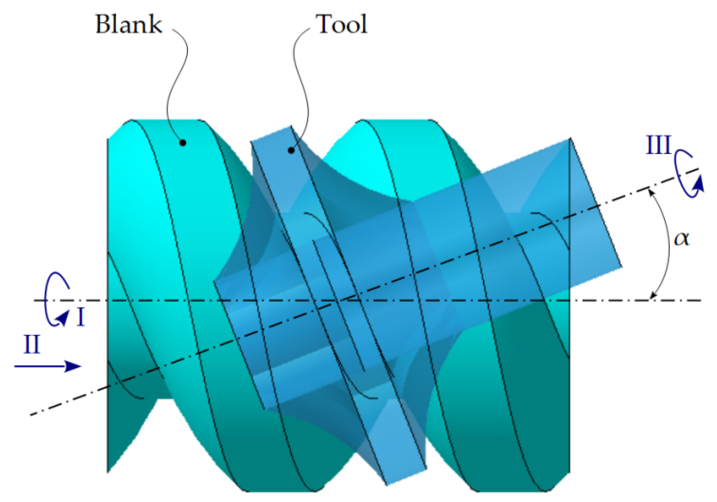
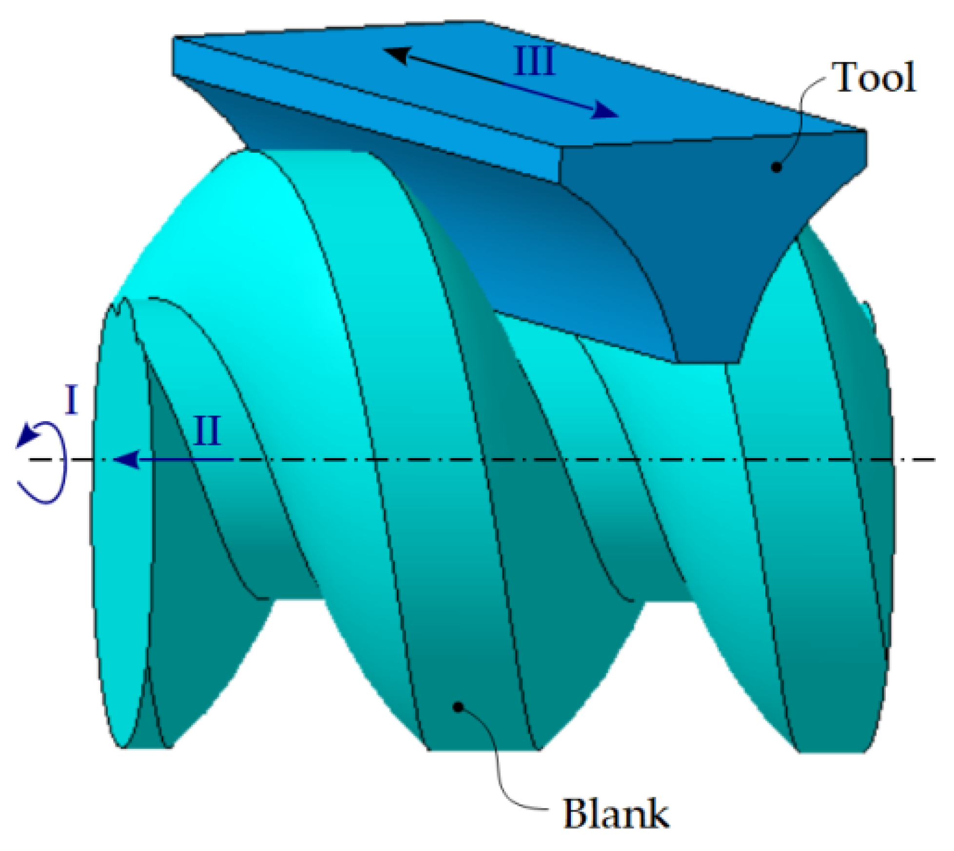
2.9.2. Generating of Helical Surfaces with Cylindrical-Front Tool—Profiling Algorithm
- -
- Rotational movement around its own axis, constituting the cutting movement;
- -
- Helical movement of the axis and parameter p (the movement of generating the helical surface).
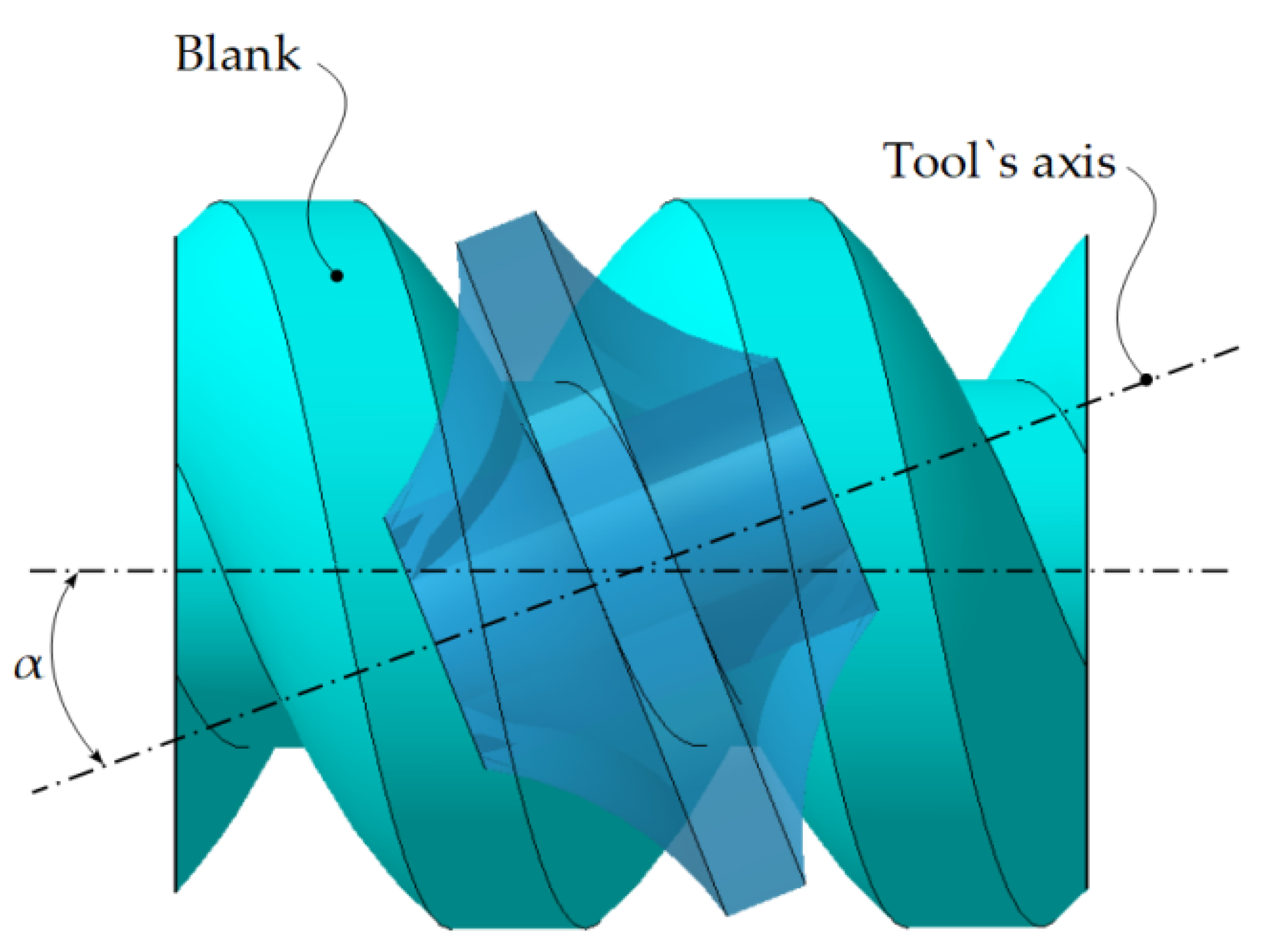
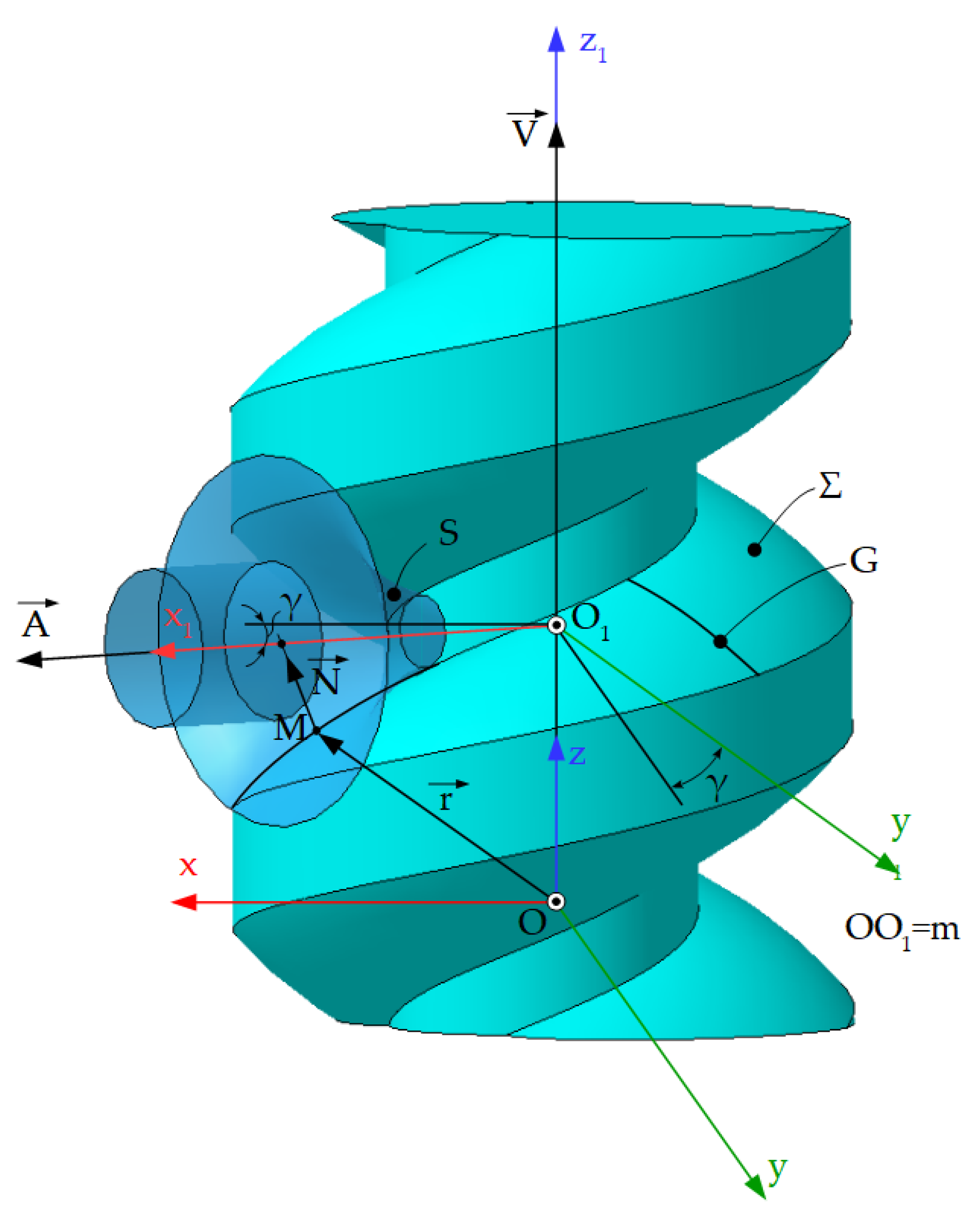
2.9.3. Generating of Helical Surfaces with Cylindrical Tools—Profiling Algorithm
- -
- Translational movement along the own generators, which constitutes the cutting movement;
- -
- Helical movement, identical with the movement of generating the helical surface by the generator, G.
3. Conclusions
Author Contributions
Funding
Institutional Review Board Statement
Informed Consent Statement
Data Availability Statement
Acknowledgments
Conflicts of Interest
References
- Radzevich, S.P. Kinematics Geometry of Surface Machining; CRC Press: London, UK, 2008. [Google Scholar]
- Oancea, N. Surfaces Generation through Winding, Vol. I–III; Galati University Press: Galati, Romania, 2004. [Google Scholar]
- Cioară, R. Kinematic Structures for Processing of Surfaces with a Circle Directrix and a Straight Line Generatrix (Part IV). IOP Conf. Ser. Mater. Sci. Eng. 2016, 161, 1–8. [Google Scholar]
- Airy, G.B. On the Forms of the Teeth of Wheels. Trans. Camb. Philos. Soc. 1827, 2, 277–286. [Google Scholar]
- Figliolini, G.; Stachel, H.; Angeles, J. Kinematic Properties of Planar and Spherical Logarithmic Spirals: Applications to the Synthesis of Involute Tooth Profiles. Mech. Mach. Theory 2019, 136, 14–26. [Google Scholar] [CrossRef]
- He, F.; Shi, Z.; Yu, B. Effects of Tooth Surface Modification on Planar Double-Enveloping Hourglass Worm Gear Drives. J. Adv. Mech. Des. Syst. Manuf. 2018, 12, 1–13. [Google Scholar] [CrossRef]
- Stanieck, R. Shaping of Face Toothing in Flat Spiroid Gears. J. Mech. Eng. 2011, 57, 47–54. [Google Scholar] [CrossRef]
- Totolici, S.; Teodor, V.G.; Baroiu, N.; Oancea, N. A New Profile for the Worm Gear Drive of a Spiral Gear. IOP Conf. Ser. Mater. Sci. Eng. 2018, 400, 1–9. [Google Scholar] [CrossRef] [Green Version]
- Carmo, M.P. Differential Geometry of Curves and Surfaces; Courier Dover Publications: New York, NY, USA, 2016. [Google Scholar]
- Phillips, J. General Spatial Involute Gearing; Springer: Berlin/Heidelberg, Germany; New York, NY, USA, 2003. [Google Scholar]
- Litvin, F.L. Theory of Gearing, Reference Publication 1212; NASA, Scientific and Technical Information Division: Washington, DC, USA, 1984. [Google Scholar]
- Teodor, V.G. Contributions to the Elaboration of a Method for Profiling Tools. Tools Which Generate by Enwrapping; Lambert Academic Publishing: Saarbrücken, Germany, 2010. [Google Scholar]
- Chan, C.L.; Ting, K.L. Extended Camus Theory and Higher Order Conjugated Curves. J. Mech. Robot. 2019, 11, 1–9. [Google Scholar] [CrossRef]
- Dana-Picard, T.; Zehavi, N. Automated study of envelopes of one-parameter families of surfaces. Springer Proc. Math. Stat. 2017, 198, 29–44. [Google Scholar]
- Dooner, D.B. On the Third Law of Gearing: A Study on Hypoid Gear Tooth Contact. Mech. Mach. Theory 2019, 134, 224–248. [Google Scholar] [CrossRef]
- Guo, Q.; Qing, G.G.; Jiang, Y. An Analytic Method of Computing the Envelope Surface of General Cutter with Runout in 5-axis Machining for Manufacturing Systems. J. Chin. Soc. Mech. Eng. 2017, 38, 403–412. [Google Scholar]
- Ding, H.; Zhou, Y.S.; Tang, J.Y.; Zhong, J.; Zhou, Z.; Wan, G. A Novel Operation Approach to Determine Initial Contact Point for Tooth Contact Analysis with Errors of Spiral Bevel and Hypoid Gears. Mech. Mach. Theory 2017, 109, 155–170. [Google Scholar] [CrossRef]
- Albu, S.C. Simulation of Processing of a Helical Surface with the Aid of a Frontal-Cylindrical Milling Tool. Procedia Manuf. 2019, 32, 36–41. [Google Scholar] [CrossRef]
- Huai, C.; Zhao, Y. Meshing Theory and Tooth Profile Geometry of Toroidal Surface Enveloping Conical Worm Drive. Mech. Mach. Theory. 2019, 134, 476–498. [Google Scholar] [CrossRef]
- Jia, K.; Zheng, S.; Guo, J.; Hong, J. A Surface Enveloping-Assisted Approach on Cutting Edge Calculation and Machining Process Simulation for Skiving. Int. J. Adv. Manuf. Technol. 2019, 100, 1635–1645. [Google Scholar] [CrossRef]
- Liu, Z.; Lu, H.; Yu, G.; Wang, S. A Novel CNC Machining Method for Enveloping Surface. Int. J. Adv. Manuf. Technol. 2016, 85, 779–790. [Google Scholar] [CrossRef]
- Liu, Z.; Tang, Q.; Liu, N.; Song, J. A Profile Error Compensation Method in Precision Grinding of Screw Rotors. Int. J. Adv. Manuf. Technol. 2019, 100, 2557–2567. [Google Scholar] [CrossRef]
- Meng, Q.; Zhao, Y.; Yang, Z. Meshing Limit Line of the Conical Surface Enveloping Conical Worm Pair. Proc. Inst. Mech. Eng. Part C J. Mech. Eng. Sci. 2020, 234, 693–703. [Google Scholar] [CrossRef]
- Meng, Q.; Zhao, Y.; Yang, Z.; Cui, J. Meshing Theory and Error Sensitivity of Mismatched Conical Surface Enveloping Conical Worm Pair. Mech. Mach. Theory 2020, 145, 103681. [Google Scholar] [CrossRef]
- Yang, J.; Li, H.; Rui, C.; Wei, W.; Dong, X. A Method to Generate the Spiral Flutes of an Hourglass Worm Gear Hob. J. Mech. Des. Trans. ASME 2018, 140, 1–12. [Google Scholar] [CrossRef]
- Zhao, Y.; Kong, X. Meshing Principle of Conical Surface Enveloping Spiroid Drive. Mech. Mach. Theory 2018, 123, 1–26. [Google Scholar] [CrossRef]
- Zhou, Y.; Wu, Y.; Wang, L.; Tang, J.; Ouyang, H. A New Closed-Form Calculation of Envelope Surface for Modeling Face Gears. Mech. Mach. Theory 2019, 137, 211–226. [Google Scholar] [CrossRef]
- Berbinschi, S.; Teodor, V.G.; Baroiu, N.; Oancea, N. The Substitutive Circles Family Method-Graphical Aproach in CATIA Design Environment. Ann. Dunarea Jos Univ. Galati Fascicle V Technol. Mach. Build. 2013, 1, 53–66. [Google Scholar]
- Baroiu, N.; Berbinschi, S.; Teodor, V.G.; Oancea, N. Comparative Study of Drill’s Flank Geometry Developed with the CATIA Software. Ann. Dunarea Jos Univ. Galati Fascicle V Technol. Mach. Build. 2012, 1, 27–32. [Google Scholar]
- Baroiu, N.; Berbinschi, S.; Teodor, V.G.; Susac, F.; Oancea, N. The Complementary Graphical Method used for Profiling Side Mill for Generation of Helical Surface. In Proceedings of the IOP Conf. Series: Materials Science and Engineering, 2017, 227, ModTech International Conference Modern Technologies in Industrial Engineering, Sibiu, Romania, 14–17 June 2017. [Google Scholar]
- Baroiu, N.; Baroiu, L.; Teodor, V.G.; Ciocan, T.L. Graphical Method for Profiling the Side Mill which Generate Helical Flute of Tungsten Carbide Dental Cross Cut Bur. Rom. J. Mater. 2018, 48, 131–139. [Google Scholar]
- Berbinschi, S.; Teodor, V.G.; Oancea, N. 3D Graphical Method for Profiling Gear Hob Tools. Int. J. Adv. Manuf. Technol. 2013, 64, 291–304. [Google Scholar] [CrossRef]
- Berbinschi, S.; Teodor, V.G.; Baroiu, N.; Oancea, N. Enwrapping Surfaces with Point Contact-Comparison between CATIA Method and Analytical One. Ann. Dunarea Jos Univ. Galati Fascicle V Technol. Mach. Build. 2011, 2, 117–122. [Google Scholar]
- Berbinschi, S.; Teodor, V.G.; Frumuşanu, G.R.; Oancea, N. Graphical Method for Profiling the Tools which Generate Internal Surfaces by Rolling. Acad. J. Manuf. Eng. 2014, 12, 12–17. [Google Scholar]
- Berbinschi, S.; Teodor, V.G.; Oancea, N. A Graphical Method Developed in CATIA Design Environment for the Modeling of Generation by Enveloping. Ann. Dunarea Jos Univ. Galati Fascicle V Technol. Mach. Build. 2011, 1, 25–30. [Google Scholar]
- Berbinschi, S.; Baroiu, N.; Teodor, V.G.; Oancea, N. Profiling Method of Side Mill for Threading Screw for Dental Implants. Adv. Mater. Res. 2014, 837, 22–27. [Google Scholar] [CrossRef]
- Teodor, V.G.; Popa, I.; Oancea, N. The profiling of End Mill and Planing Tools to Generate Helical Surfaces Known by Sampled Points. Int. J. Adv. Manuf. Technol. 2010, 51, 439–452. [Google Scholar] [CrossRef]
- Teodor, V.G.; Popa, I.; Popa, C.; Dura, G.; Oancea, N. Algorithm for Gear Hub Tool Profiling by Bezier Polynomial Approximation. The Rotary Helical Screw Compressor Case. In Proceedings of the 8th WSEAS International Conference on System Science and Simulation in Engineering (ICOSSSE’09), Genova, Italy, 17–19 October 2009. [Google Scholar]
- Baroiu, N.; Teodor, V.G.; Susac, F.; Oancea, N. Hob mill for trilobed rotor-Graphical method in CATIA. IOP Conf. Ser. Mater. Sci. Eng. 2018, 448, 1–17. [Google Scholar] [CrossRef]
- Teodor, V.G.; Baroiu, N.; Berbinschi, S.; Susac, F.; Oancea, N. A Graphical Solution in CATIA for Profiling End Mill Tool which Generates a Helical Surface. IOP Conf. Ser. Mater. Sci. Eng. 2017, 227, 1–15. [Google Scholar] [CrossRef] [Green Version]
- Teodor, V.G.; Baroiu, N.; Susac, F. The Synthesis of New Algorithms for CAD Profiling of Cutting Tools; Lambert Academic Publishing: Saarbrücken, Germany, 2018. [Google Scholar]
- Baroiu, N.; Teodor, V.G.; Susac, F.; Oancea, N. Hob Mill Profiling Method for Generation of Timing Belt Pulley. In Proceedings of the 5th International Conference on Advanced Manufacturing and Technologies (NewTech), Belgrade, Serbia, 6–9 June 2017; pp. 13–26. [Google Scholar]
- Hong, X.; Hong, R.; Lin, X. Tool Orientations’ Generation and Nonlinear Error Control based on Complex Surface Meshing. Int. J. Adv. Manuf. Technol. 2019, 105, 4279–4288. [Google Scholar] [CrossRef]
- Wang, Q.; Feng, Y.; Gao, Y.; Li, Z.; Tan, J. Smooth Fillet-End Cutter Tool Path Generation Method on Triangular-Mesh Surface Based on Modified Butterfly Subdivision. Int. J. Adv. Manuf. Technol. 2018, 98, 2831–2847. [Google Scholar] [CrossRef]
- Cera, M.; Pennestrì, E. The Mechanical Generation of Planar Curves by Means of Point Trajectories, Line and Circle Envelopes: A Unified Treatment of the Classic and Generalized Burmester Problem. Mech. Mach. Theory 2019, 142, 103580. [Google Scholar] [CrossRef]
- Cera, M.; Pennestrì, E. Higher-order curvature analysis of planar curves enveloped by straight-lines. Mech. Mach. Theory 2019, 134, 213–223. [Google Scholar] [CrossRef]
- Gouchao, L.; Sun, J.; Jianfeng, L. Process Modeling of End Mill Groove Machining Based on Boolean Method. Int. J. Adv. Manuf. Technol. 2014, 57, 959–966. [Google Scholar]
- Guo, Q.; Sun, Y.; Jiang, Y.; Yan, Y.; Zhao, B.; Ming, P. Tool Path Optimization for Five-Axis Flank Milling with Cutter Runout Effect Using the Theory of Envelope Surface Based on CL Data for General Tools. J. Manuf. Syst. 2016, 38, 87–97. [Google Scholar] [CrossRef]
- Liu, G.; Wei, W.; Dong, X.; Rui, C.; Liu, P.; Li, H. Relief Grinding of Planar Double-Enveloping Worm Gear Hob Using a Four-Axis CNC Grinding Machine. Int. J. Adv. Manuf. Technol. 2016, 89, 9–12. [Google Scholar] [CrossRef]
- Nieszporek, T.; Boral, P.; Gołȩbski, R. Particular Solution of Cutting Tool Path Applied on Helical Surface with Circular Profile. Teh. Vjesn. 2019, 26, 22–28. [Google Scholar]
- Oancea, N. Méthode numérique pour l’étude des surfaces enveloppées. Mech. Mach. Theory 1996, 31, 957–972. [Google Scholar]
- Dooner, D.B.; Griffis, M.W. On spatial Euler-Savary Equations for Envelopes. J. Mech. Des. Trans. ASME 2007, 129, 865–875. [Google Scholar] [CrossRef]
- Berbinschi, S.; Teodor, V.G.; Oancea, N. A 3D Method for Profiling the Shaping Tool for the Generation of Helical Surfaces. Ann. Dunarea Jos Univ. Galati Fascicle V Technol. Mach. Build. 2011, 1, 19–24. [Google Scholar]
- Baroiu, N.; Teodor, V.G.; Oancea, N. A New Form of Plane Trajectories Theorem. Generation with Rotary Cutter. Bull. Polytech. Inst. Iasi 2015, 3, 27–36. [Google Scholar]
- Baroiu, N.; Teodor, V.G.; Popa, C.; Oancea, N. Gear Shaped Cutter–A Profiling Method Developed in Graphical Form. Ann. Dunarea Jos Univ. Galati Fascicle V Technol. Mach. Build. 2015, 33, 9–16. [Google Scholar]
- Teodor, V.G.; Baroiu, N.; Susac, F.; Oancea, N. The Modelling of Involute Teeth Generation with the Relative Generating Trajectories Method. Acad. J. Manuf. Eng. 2016, 14, 126–131. [Google Scholar]
- Teodor, V.G.; Baroiu, N.; Susac, F.; Oancea, N. The Rack-Gear Tool Generation Modelling. Non-Analytical Method Developed in CATIA, Using the Relative Generating Trajectories Method. IOP Conf. Ser. Mater. Sci. Eng. 2016, 161, 1–6. [Google Scholar] [CrossRef] [Green Version]
- Teodor, V.G.; Păunoiu, V.; Berbinschi, S.; Baroiu, N.; Oancea, N. The Method of ”In-Plane Generating Trajectories” for Tools Which Generate By Enveloping-Application in CATIA. J. Mach. Eng. 2015, 15, 69–80. [Google Scholar]
- Berbinschi, S.; Frumuşanu, G.; Teodor, V.G.; Oancea, N. The method of substitutive circles family. Application in CATIA design environment for gear shaped tool profiling. Adv. Mater. Res. 2014, 1036, 370–375. [Google Scholar] [CrossRef]
- Berbinschi, S.; Teodor, V.G.; Frumușanu, G.R.; Oancea, N. The pinion cutter for profiled holes-Graphical method in CATIA. Appl. Mech. Mater. 2014, 657, 720–724. [Google Scholar] [CrossRef]
- Teodor, V.G.; Berbinschi, S.; Baroiu, N.; Oancea, N. Study of the Enwrapping Profiles Associated with Rolling Centrodes by the Minimum Distance Method. Graphical Solution Developed in the CATIA Design Environment. Appl. Mech. Mater. 2014, 656, 181–191. [Google Scholar] [CrossRef]
- Popa, L.C.; Popa, I.; Teodor, V.G.; Baroiu, N. Profiling Tool Generating Method using the Profile Measurement of Rotor of Screw Compressor Components. Ann. Dunarea Jos Univ. Galati Fascicle V Technol. Mach. Build. 2011, 2, 123–128. [Google Scholar]
- Baroiu, N.; Moroșanu, G.A.; Teodor, V.G.; Oancea, N. Roller Profiling for Generating the Screw of a Pump with Progressive Cavities. Inventions 2021, 6, 34. [Google Scholar] [CrossRef]
- Bo, P.; Bartoň, M.; Plakhotnik, D.; Pottmann, H. Towards efficient 5-axis flank CNC machining of free-form surfaces via fitting envelopes of surfaces of revolution. Comput. -Aided Des. 2016, 79, 1–11. [Google Scholar] [CrossRef] [Green Version]
- Wang, W.; Wang, D. Curvature Theory of Envelope Curve in Two-Dimensional Motion and Envelope Surface in Three-Dimensional Motion. J. Mech. Robot. 2015, 7, 1–9. [Google Scholar] [CrossRef]
- Zanger, F.; Sellmeier, V.; Klose, J.; Bartkowiak, M.; Schulze, V. Comparison of Modeling Methods to Determine Cutting Tool Profile for Conventional and Synchronized Whirling. Procedia CIRP 2017, 58, 222–227. [Google Scholar] [CrossRef]
- Hu, P.; Chen, L.; Tang, K. Efficiency-Optimal Iso-Planar Tool Path Generation for Five-Axis Finishing Machining of Freeform Surfaces. Comput. -Aided Des. 2018, 83, 33–50. [Google Scholar] [CrossRef]
- Berbinschi, S.; Teodor, V.G.; Baroiu, N.; Oancea, N. Profiling Methodology for Side Mill Tools for Generation of Helical Compressor Rotor Using Reverse Engineering. Ann. Dunarea Jos Univ. Galati Fascicle V Technol. Mach. Build. 2011, 2, 111–116. [Google Scholar]
- Berbinschi, S.; Teodor, V.G.; Oancea, N. 3D Graphical Method for Profiling Tools that Generate Helical Surfaces. Int. J. Adv. Manuf. Technol. 2012, 60, 505–512. [Google Scholar] [CrossRef]
- Berbinschi, S.; Baroiu, N.; Teodor, V.G.; Oancea, N. End Mill Tool Profiling by CAD Method. Indian J. Eng. Mater. Sci. 2014, 21, 296–302. [Google Scholar]


Publisher’s Note: MDPI stays neutral with regard to jurisdictional claims in published maps and institutional affiliations. |
© 2022 by the authors. Licensee MDPI, Basel, Switzerland. This article is an open access article distributed under the terms and conditions of the Creative Commons Attribution (CC BY) license (https://creativecommons.org/licenses/by/4.0/).
Share and Cite
Moroşanu, G.A.; Baroiu, N.; Teodor, V.G.; Păunoiu, V.; Oancea, N. Review on Study Methods for Reciprocally Enwrapping Surfaces. Inventions 2022, 7, 10. https://doi.org/10.3390/inventions7010010
Moroşanu GA, Baroiu N, Teodor VG, Păunoiu V, Oancea N. Review on Study Methods for Reciprocally Enwrapping Surfaces. Inventions. 2022; 7(1):10. https://doi.org/10.3390/inventions7010010
Chicago/Turabian StyleMoroşanu, Georgiana Alexandra, Nicuşor Baroiu, Virgil Gabriel Teodor, Viorel Păunoiu, and Nicolae Oancea. 2022. "Review on Study Methods for Reciprocally Enwrapping Surfaces" Inventions 7, no. 1: 10. https://doi.org/10.3390/inventions7010010