Using a Digital Microfluidic System to Evaluate the Stretch Length of a Droplet with a L-DEP and Varied Parameters


Abstract
:1. Introduction
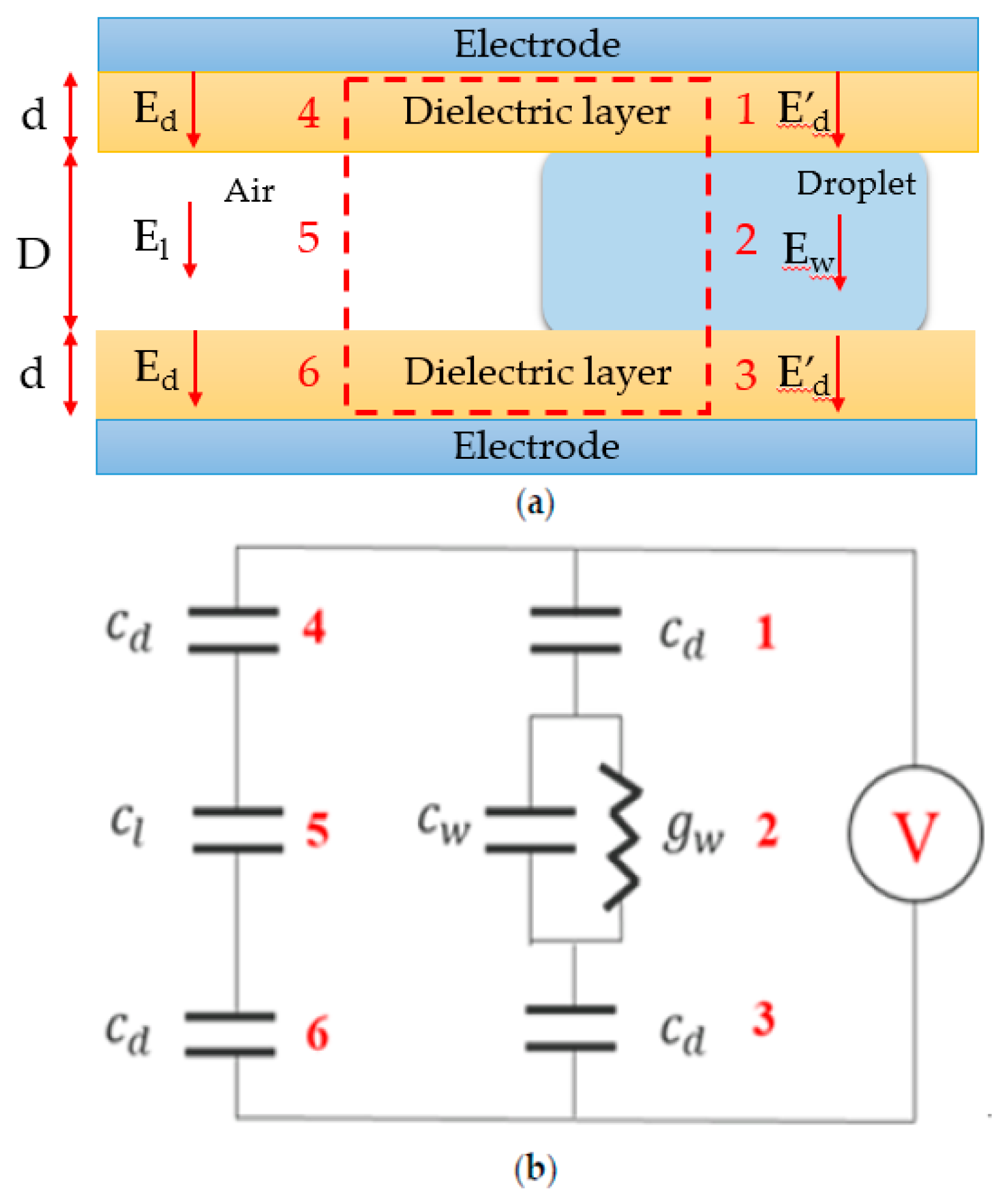
2. Theory
3. Experiments
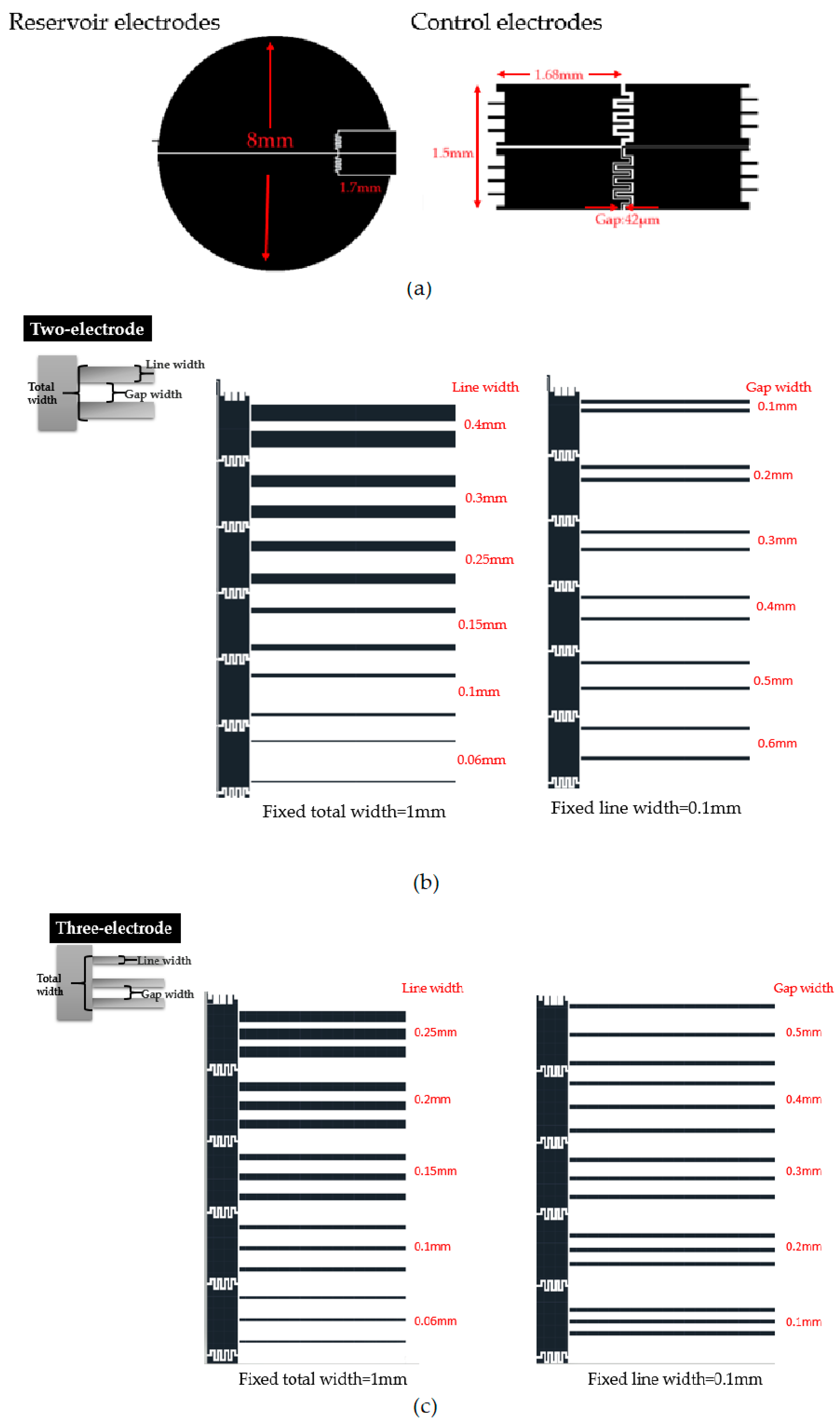
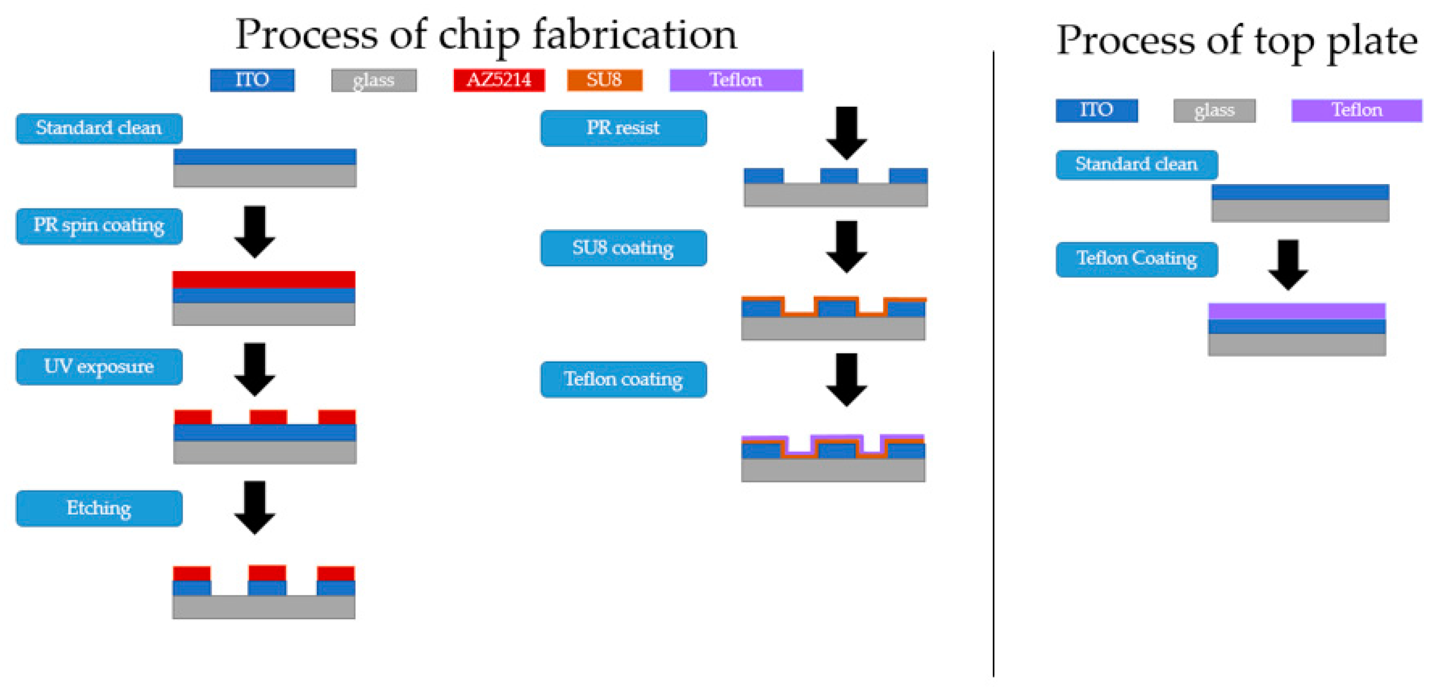
3.1. L-DEP Chip Design and Fabrication
3.2. Digital Microfluidics System
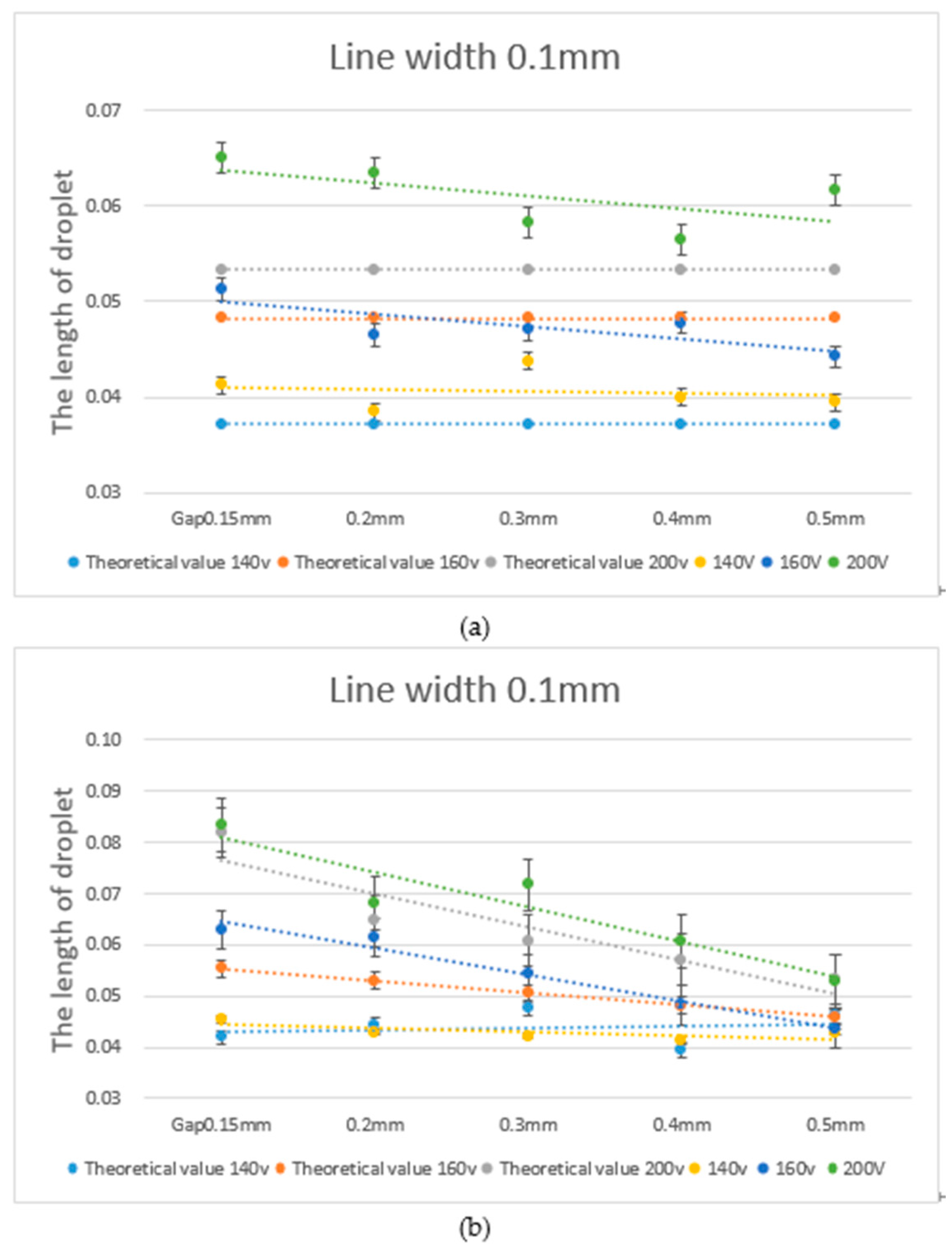
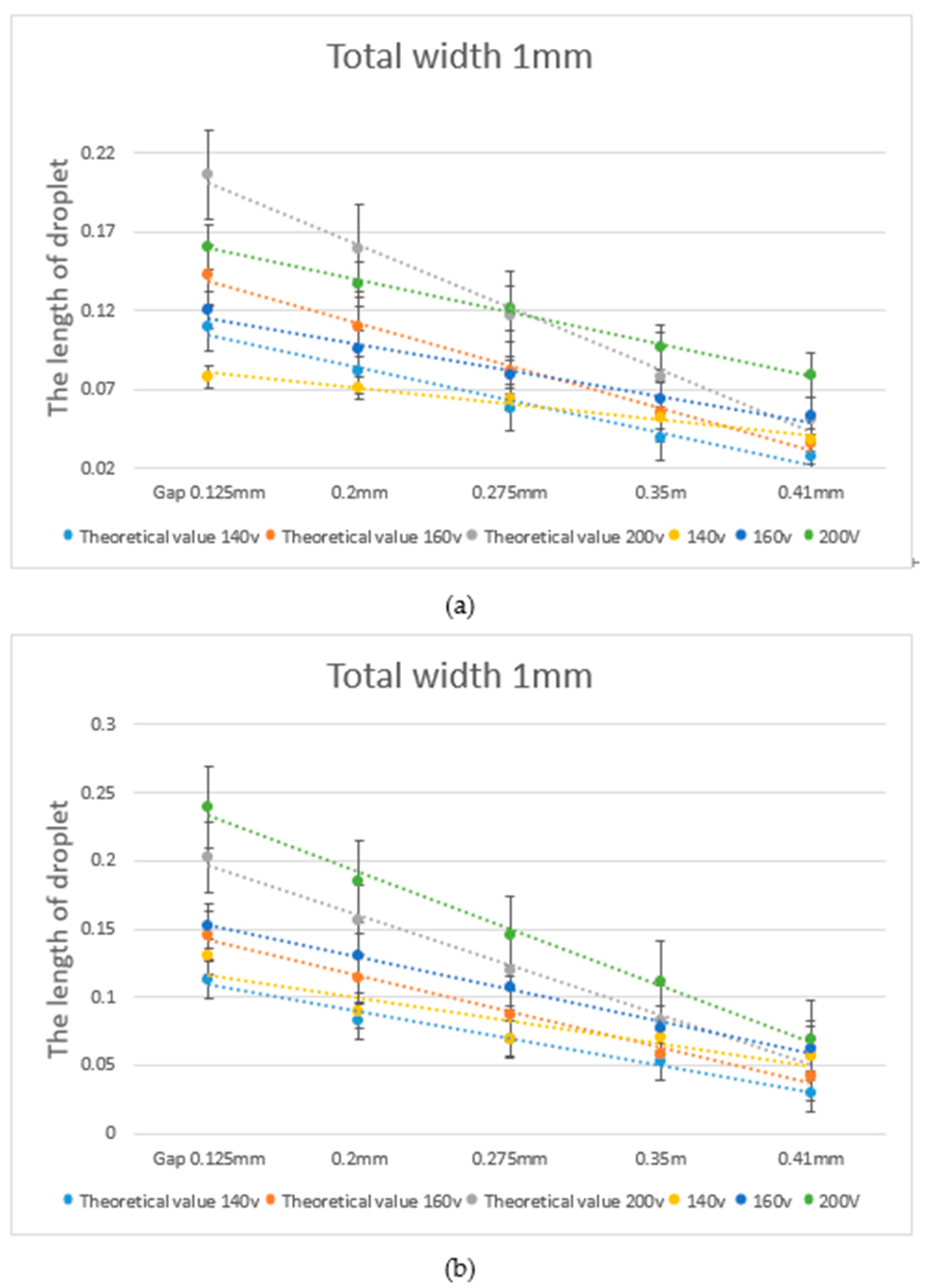
4. Results
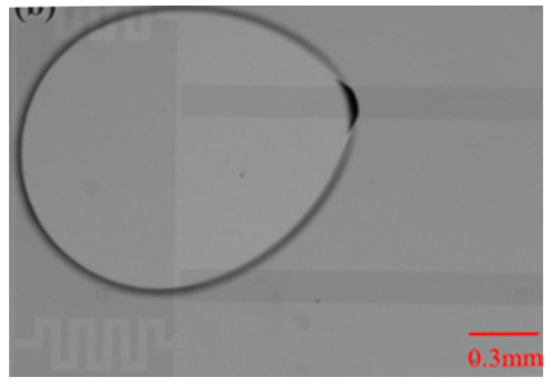
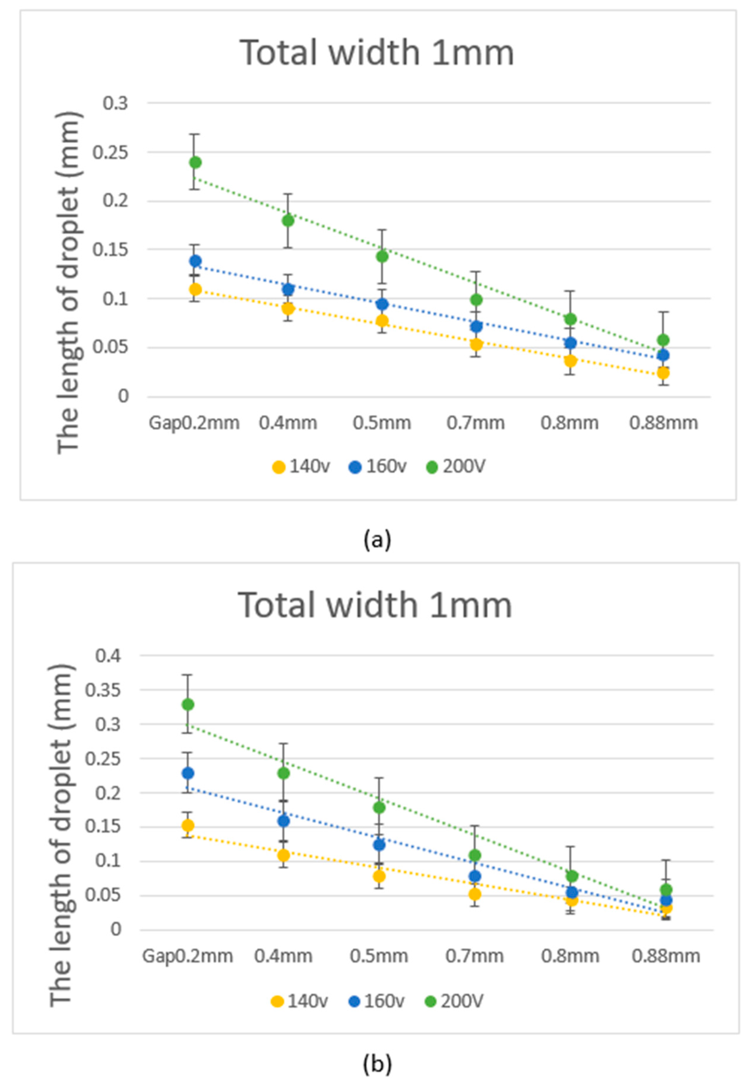
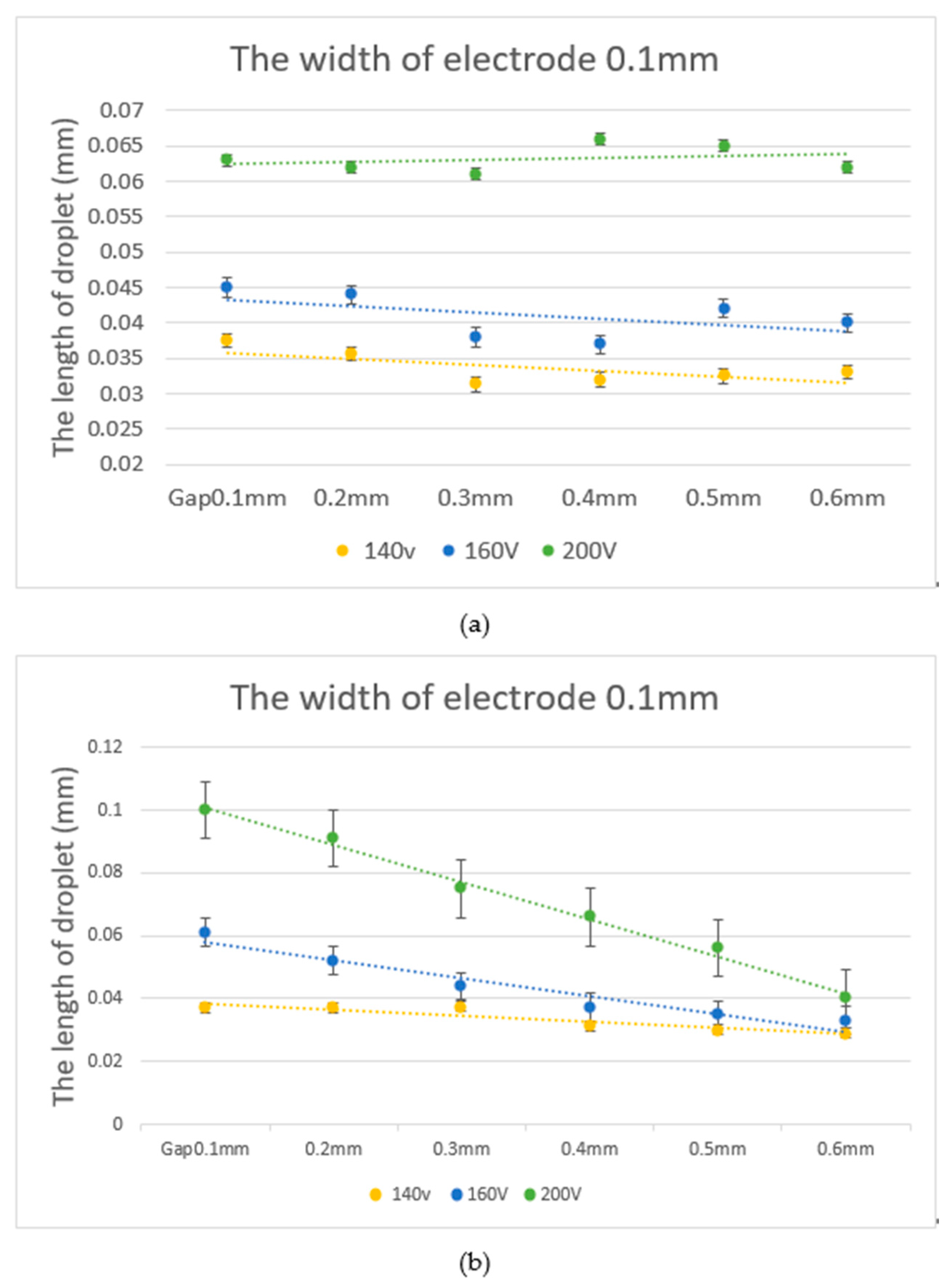
4.1. Experiment with the Two-Electrode L-DEP Chip
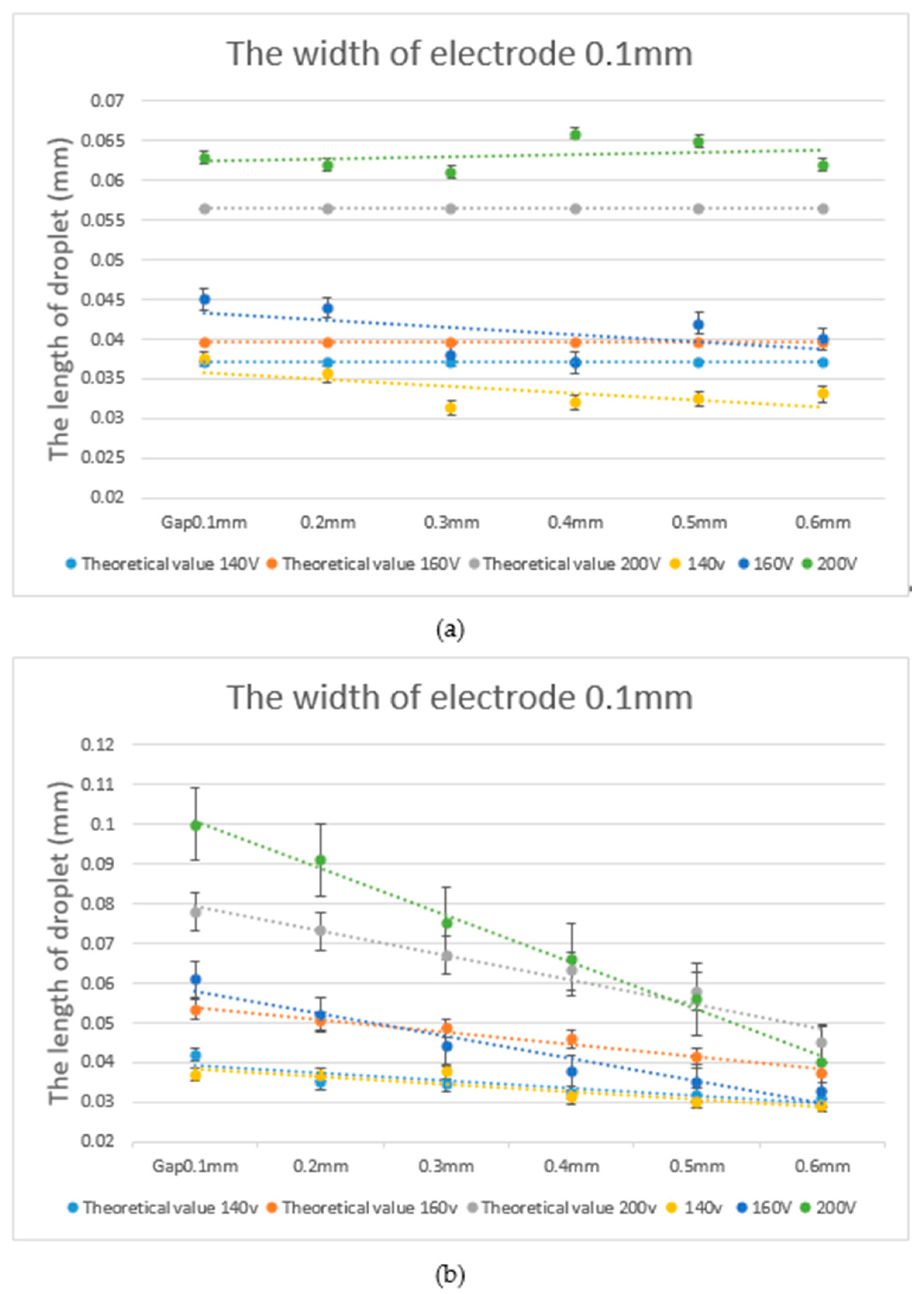
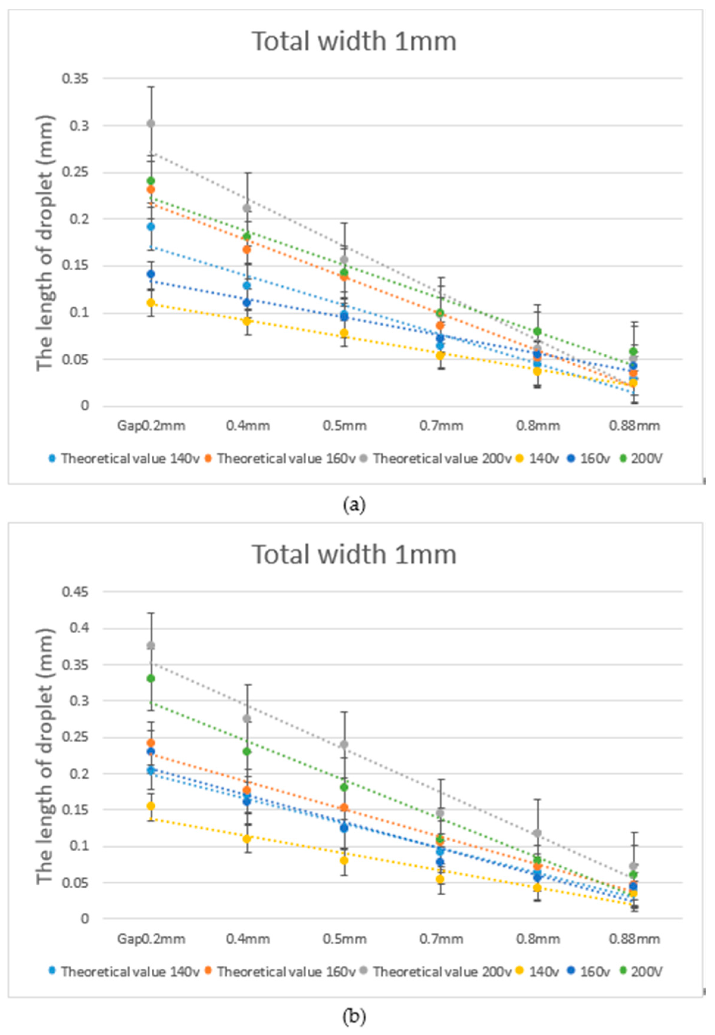
4.2. Comparison between Experimental Data and Theoretical Calculations
5. Conclusions
Author Contributions
Funding
Conflicts of Interest
References
- Bhatia, S.N.; Ingber, D.E. Microfluidic organs-on-chips. Nat. Biotechnol. 2014, 32, 760. [Google Scholar] [CrossRef] [PubMed]
- Elvira, K.S.; i Solvas, X.C.; Wootton, R.C.; Demello, A.J. The past, present and potential for microfluidic reactor technology in chemical synthesis. Nat. Chem. 2013, 5, 905. [Google Scholar] [CrossRef]
- Trantidou, T.; Elani, Y.; Parsons, E.; Ces, O. Hydrophilic surface modification of PDMS for droplet microfluidics using a simple, quick, and robust method via PVA deposition. Microsyst. Nanoeng. 2017, 3, 16091. [Google Scholar] [CrossRef] [PubMed]
- Samiei, E.; Tabrizian, M.; Hoorfar, M. A review of digital microfluidics as portable platforms for lab-on a-chip applications. Lab Chip 2016, 16, 2376–2396. [Google Scholar] [CrossRef]
- Dixon, C.; Ng, A.H.; Fobel, R.; Miltenburg, M.B.; Wheeler, A.R. An inkjet printed, roll-coated digital microfluidic device for inexpensive, miniaturized diagnostic assays. Lab Chip 2016, 16, 4560–4568. [Google Scholar] [CrossRef] [PubMed] [Green Version]
- Ng, A.H.; Fobel, R.; Fobel, C.; Lamanna, J.; Rackus, D.G.; Summers, A.; Dixon, C.; Dryden, M.D.; Lam, C.; Ho, M. A digital microfluidic system for serological immunoassays in remote settings. Sci. Transl. Med. 2018, 10, eaar6076. [Google Scholar] [CrossRef] [PubMed] [Green Version]
- Zhang, Y.; Nguyen, N.-T. Magnetic digital microfluidics–a review. Lab Chip 2017, 17, 994–1008. [Google Scholar] [CrossRef] [PubMed]
- Antfolk, M.; Laurell, T. Continuous flow microfluidic separation and processing of rare cells and bioparticles found in blood–A review. Anal. Chim. Acta 2017, 965, 9–35. [Google Scholar] [CrossRef]
- Zhang, Y.; Jiang, H.-R. A review on continuous-flow microfluidic PCR in droplets: Advances, challenges and future. Anal. Chim. Acta 2016, 914, 7–16. [Google Scholar] [CrossRef] [Green Version]
- Davidson, S.M.; Andersen, M.B.; Mani, A. Chaotic induced-charge electro-osmosis. Phys. Rev. Lett. 2014, 112, 128302. [Google Scholar] [CrossRef]
- Davidson, S.M.; Wessling, M.; Mani, A. On the dynamical regimes of pattern-accelerated electroconvection. Sci. Rep. 2016, 6, 22505. [Google Scholar] [CrossRef] [PubMed]
- Gough, R.C.; Morishita, A.M.; Dang, J.H.; Moorefield, M.R.; Shiroma, W.A.; Ohta, A.T. Rapid electrocapillary deformation of liquid metal with reversible shape retention. Micro Nano Syst. Lett. 2015, 3, 4. [Google Scholar] [CrossRef] [Green Version]
- Clement, C.E.; Thio, S.K.; Park, S.-Y. An optofluidic tunable Fresnel lens for spatial focal control based on electrowetting-on-dielectric (EWOD). Sens. Actuators B Chem. 2017, 240, 909–915. [Google Scholar] [CrossRef]
- Jain, V.; Hole, A.; Deshmukh, R.; Patrikar, R. Dynamic capacitive sensing of droplet parameters in a low-cost open EWOD system. Sens. Actuators A Phys. 2017, 263, 224–233. [Google Scholar] [CrossRef]
- Jones, T.B.; Gunji, M.; Washizu, M.; Feldman, M. Dielectrophoretic liquid actuation and nanodroplet formation. J. Appl. Phys. 2001, 89, 1441–1448. [Google Scholar] [CrossRef]
- Renaudot, R.; Daunay, B.; Kumemura, M.; Agache, V.; Jalabert, L.; Collard, D.; Fujita, H. Optimized micro devices for liquid-dielectrophoresis (LDEP) actuation of conductive solutions. Sens. Actuators B Chem. 2013, 177, 620–626. [Google Scholar] [CrossRef]
- Agastin, S.; King, M.R.; Jones, T.B. Rapid enrichment of biomolecules using simultaneous liquid and particulate dielectrophoresis. Lab Chip 2009, 9, 2319–2325. [Google Scholar] [CrossRef]
- Lin, T.-H.; Yao, D.-J. Applications of EWOD systems for DNA reaction and analysis. J. Adhes. Sci. Technol. 2012, 26, 1789–1804. [Google Scholar] [CrossRef]
- Cho, S.K.; Moon, H.; Kim, C.-J. Creating, transporting, cutting, and merging liquid droplets by electrowetting-based actuation for digital microfluidic circuits. J. Microelectromech. Syst. 2003, 12, 70–80. [Google Scholar]
- Jones, T.B.; Wang, K.-L.; Yao, D.-J. Frequency-dependent electromechanics of aqueous liquids: Electrowetting and dielectrophoresis. Langmuir 2004, 20, 2813–2818. [Google Scholar] [CrossRef]
- Ahmed, R.; Jones, T. Optimized liquid DEP droplet dispensing. J. Micromech. Microeng. 2007, 17, 1052. [Google Scholar] [CrossRef] [Green Version]
- Prakash, R.; Paul, R.; Kaler, K.V. Liquid DEP actuation and precision dispensing of variable volume droplets. Lab Chip 2010, 10, 3094–3102. [Google Scholar] [CrossRef]
- Chen, C.-H.; Tsai, S.-L.; Jang, L.-S. Droplet creation using liquid dielectrophoresis. Sens. Actuators B Chem. 2009, 142, 369–376. [Google Scholar] [CrossRef]
- Shapiro, B.; Moon, H.; Garrell, R.L.; Kim, C.-J.C. Equilibrium behavior of sessile drops under surface tension, applied external fields, and material variations. J. Appl. Phys. 2003, 93, 5794–5811. [Google Scholar] [CrossRef] [Green Version]
- Wang, R.; Zhang, L.; Gao, M.; Wang, Q.; Deng, Z.; Gui, L. A Liquid-Metal-Based Dielectrophoretic Microdroplet Generator. Micromachines 2019, 10, 769. [Google Scholar] [CrossRef] [PubMed] [Green Version]
- Wang, K.; Jones, T.; Raisanen, A. Dynamic control of DEP actuation and droplet dispensing. J. Micromech. Microeng. 2006, 17, 76. [Google Scholar] [CrossRef]
- Ren, H.; Fair, R.B.; Pollack, M.G.; Shaughnessy, E.J. Dynamics of electro-wetting droplet transport. Sens. Actuators B Chem. 2002, 87, 201–206. [Google Scholar] [CrossRef]
- Wang, K.-L.; Jones, T. Electrowetting dynamics of microfluidic actuation. Langmuir 2005, 21, 4211–4217. [Google Scholar] [CrossRef]


© 2020 by the authors. Licensee MDPI, Basel, Switzerland. This article is an open access article distributed under the terms and conditions of the Creative Commons Attribution (CC BY) license (http://creativecommons.org/licenses/by/4.0/).
Share and Cite
Lee, H.-T.; Ciou, Y.-J.; Yao, D.-J. Using a Digital Microfluidic System to Evaluate the Stretch Length of a Droplet with a L-DEP and Varied Parameters. Inventions 2020, 5, 21. https://doi.org/10.3390/inventions5020021
Lee H-T, Ciou Y-J, Yao D-J. Using a Digital Microfluidic System to Evaluate the Stretch Length of a Droplet with a L-DEP and Varied Parameters. Inventions. 2020; 5(2):21. https://doi.org/10.3390/inventions5020021
Chicago/Turabian StyleLee, Hsiang-Ting, Ying-Jhen Ciou, and Da-Jeng Yao. 2020. "Using a Digital Microfluidic System to Evaluate the Stretch Length of a Droplet with a L-DEP and Varied Parameters" Inventions 5, no. 2: 21. https://doi.org/10.3390/inventions5020021