Digital Twins-Assisted Design of Next-Generation Advanced Controllers for Power Systems and Electronics: Wind Turbine as a Case Study

 ,
,
Abstract
:1. Introduction and Preliminaries
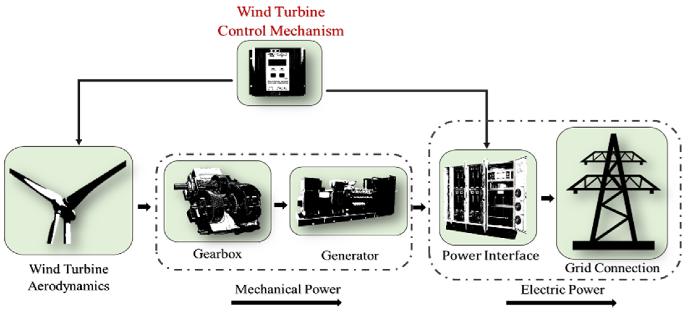
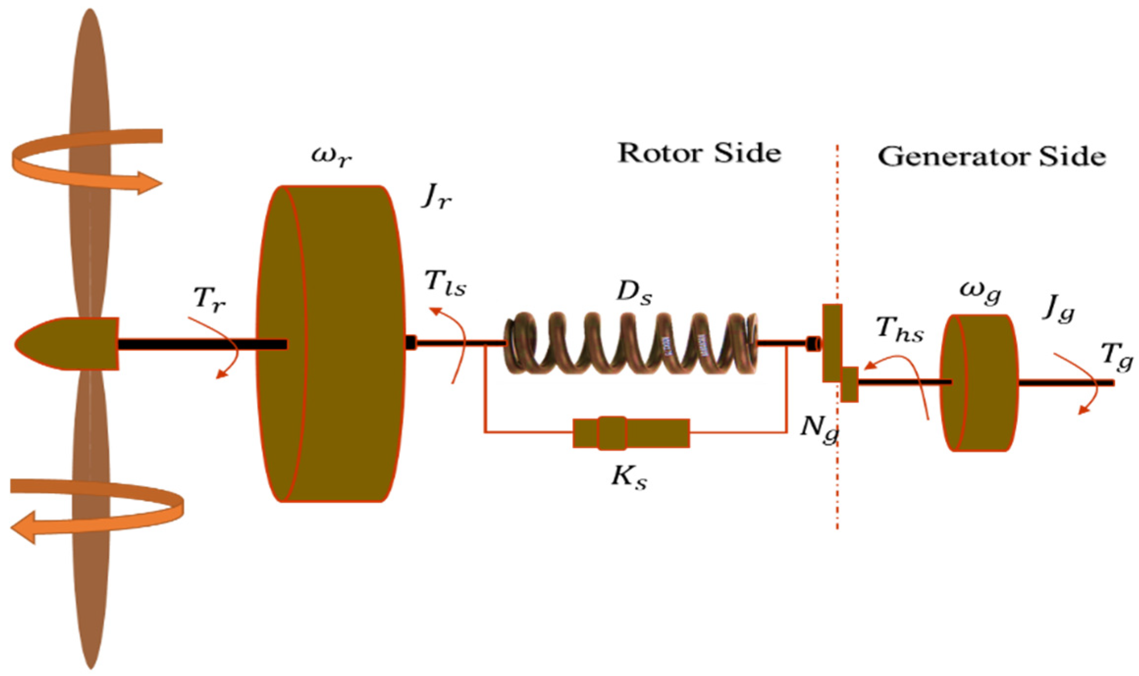
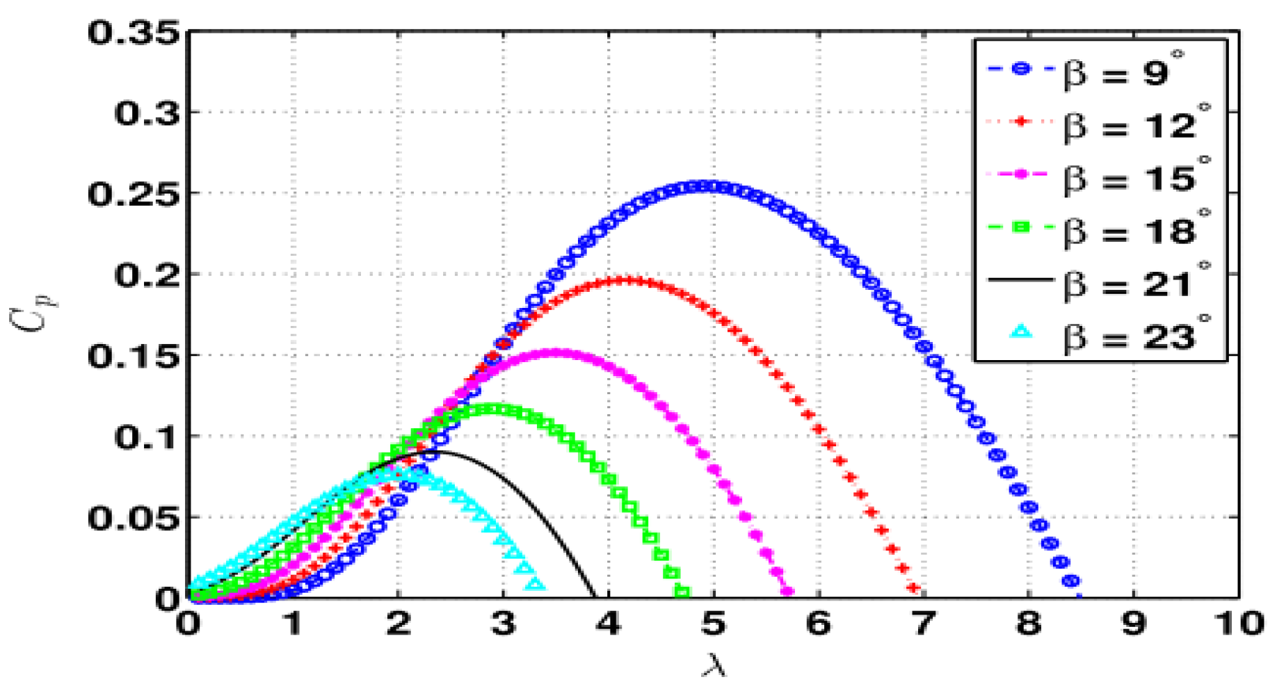
2. Variable Speed Wind Turbine Model
3. Design of Proposed Controller
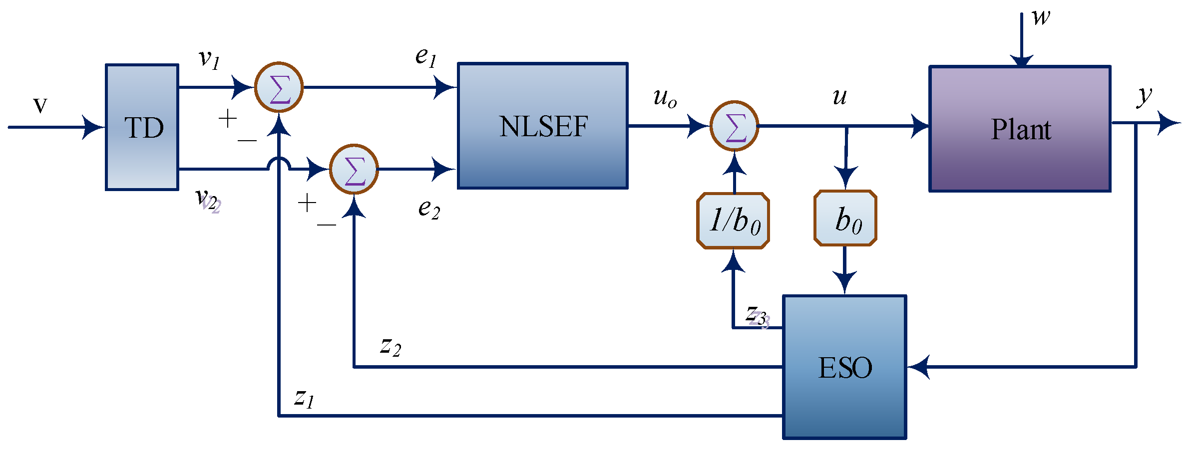
3.1. ADRC Technique
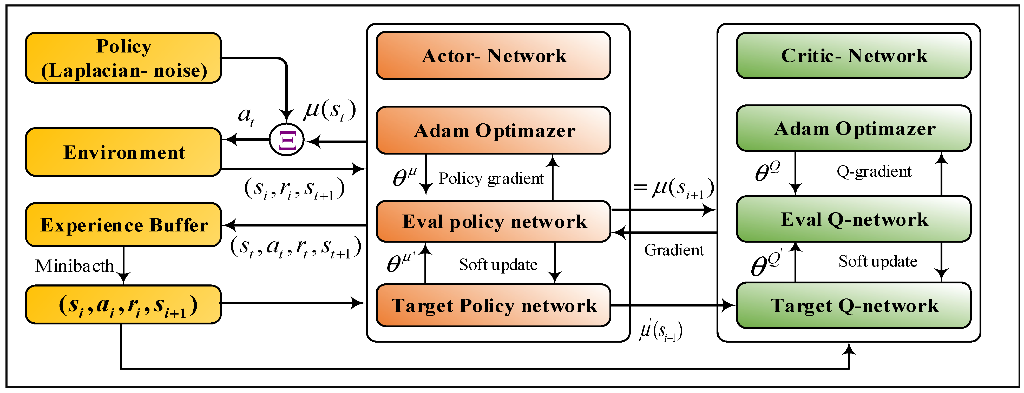
3.2. Deep Reinforcement Learning
- Environment: Space through which the agent moves and responds to the agent. The environment takes the agent’s current state and action as input and returns as output the agent’s reward and its next state.
- Agent: An agent tries to find an optimal policy to map the state of the environment to an action that will maximize the rewards of accumulated future in turn.State : is state-space or all possible states of the agent in the environment.
- Policy (π): The policy is the strategy that the agent employs to determine the next action based on the current state. It maps states to actions, the actions that promise the highest reward.
- Action It is the set of all possible moves that the agent can make.
- Reward (): A reward is feedback by which the success or failure of an agent’s actions in a given state is evaluated.
- Value function It is the expected long-term return with a discount, as opposed to the short-term reward.
- Q-value or action-value (Q): Q-value is similar to , except that it takes an extra parameter, the current action .
| Algorithm 1: Framework of the DDPG for the WMR system. |
| 1: Randomly initialize critic and actor networks with weights and |
| 2: Initialize target networks and with weights , |
| 3: Set up empty replay buffer |
| 4: for episode = to do |
| 5: Begin with a Laplacian noise for exploration |
| 6: Receive initial observation state |
| 7: for t = to do |
| 8: Apply action to environment |
| 9: Observe next state and reward |
| 10: Store following transitions into replay buffer |
| 11: Sample random minibatch of transitions from |
| 12: Set |
| 13: Update critic by the loss: |
|
14: Update the actor policy using the sampled policy gradient: |
|
15: Update the target networks: |
| 16: end for |
| 17: end for |
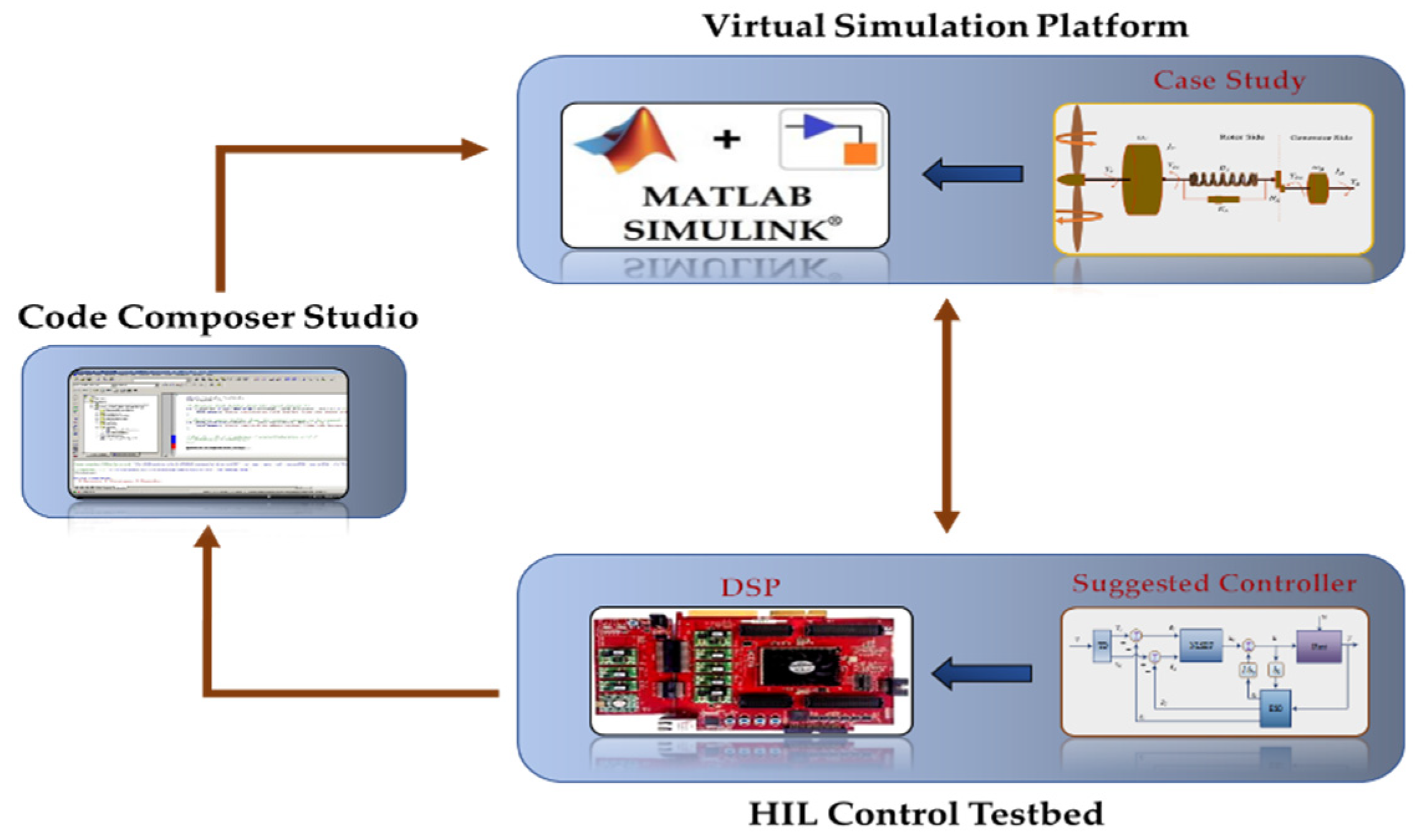
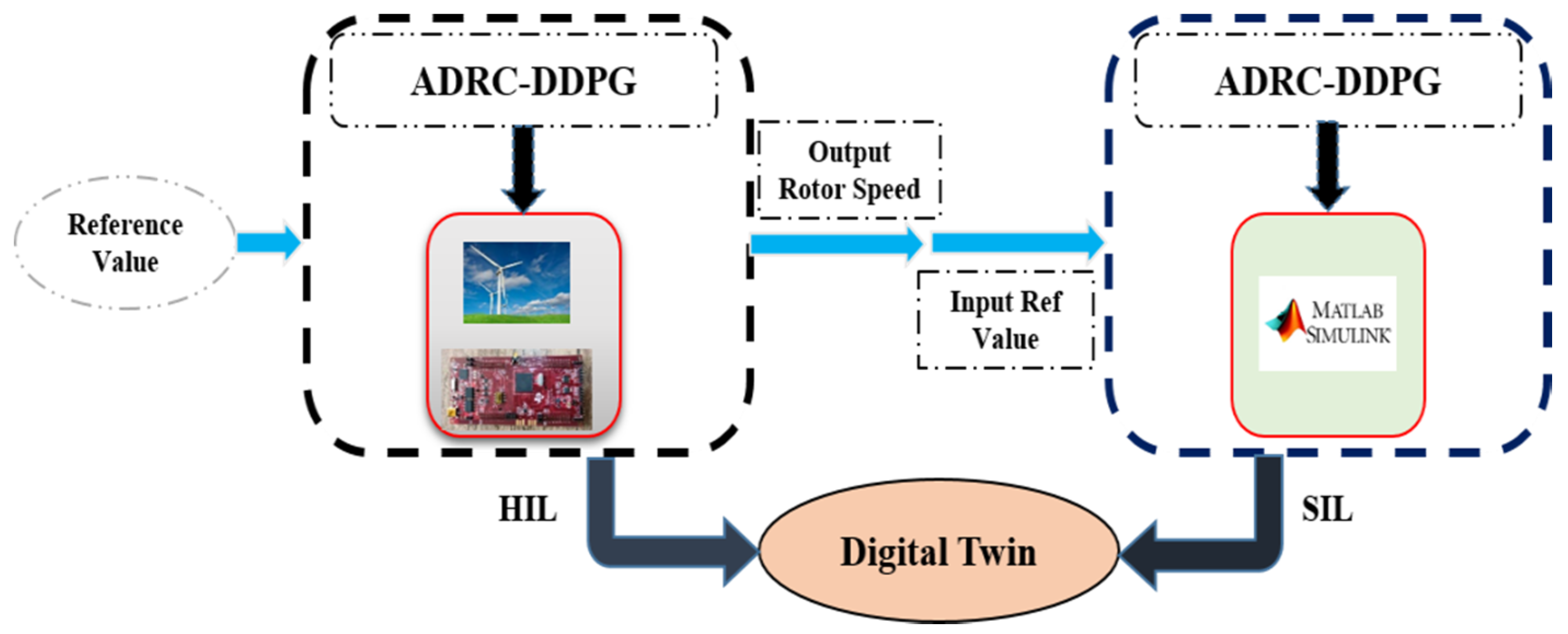
4. Digital Twin Controller of WT System
4.1. Design of the HIL Controller
4.2. Design of the Digital Twin Controller Based on the System Output Specification of the HIL Setup
5. Experimental Results
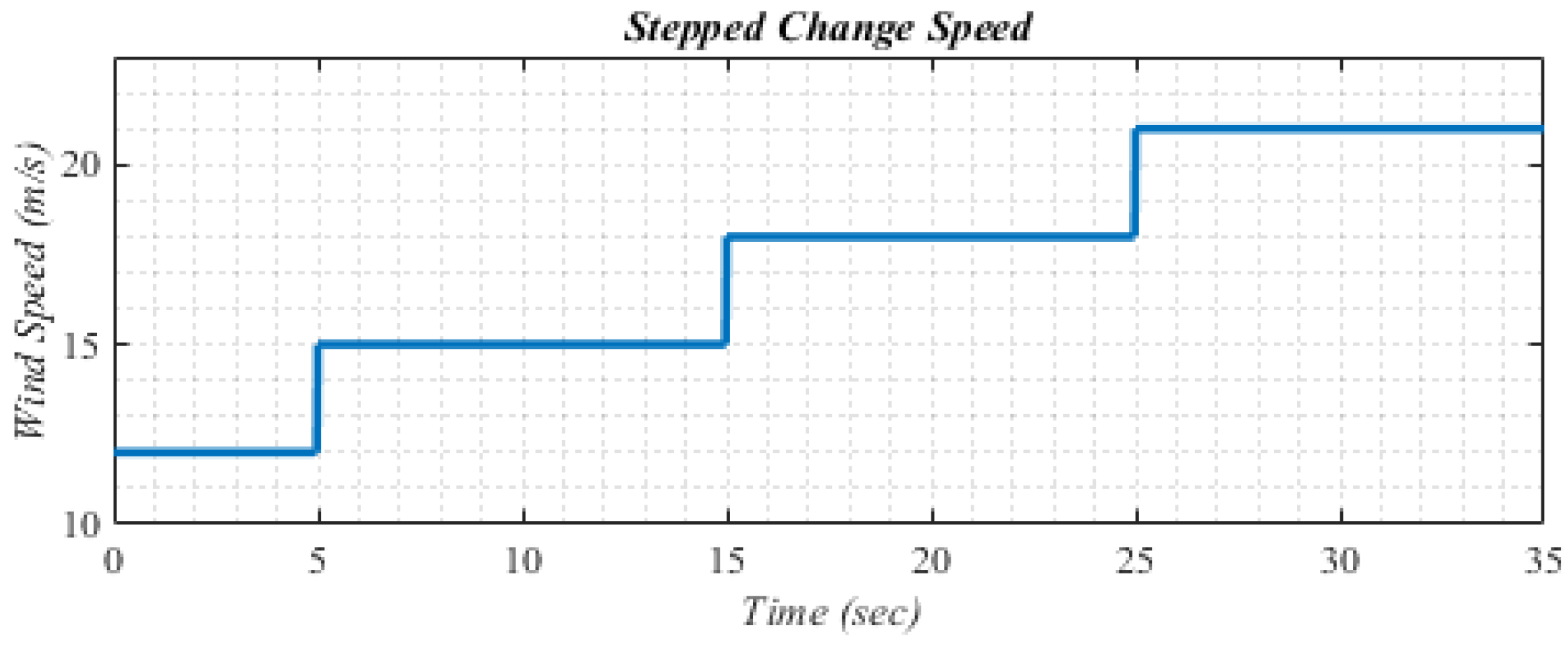
5.1. Scenario I: The Step Changes in Wind Speed
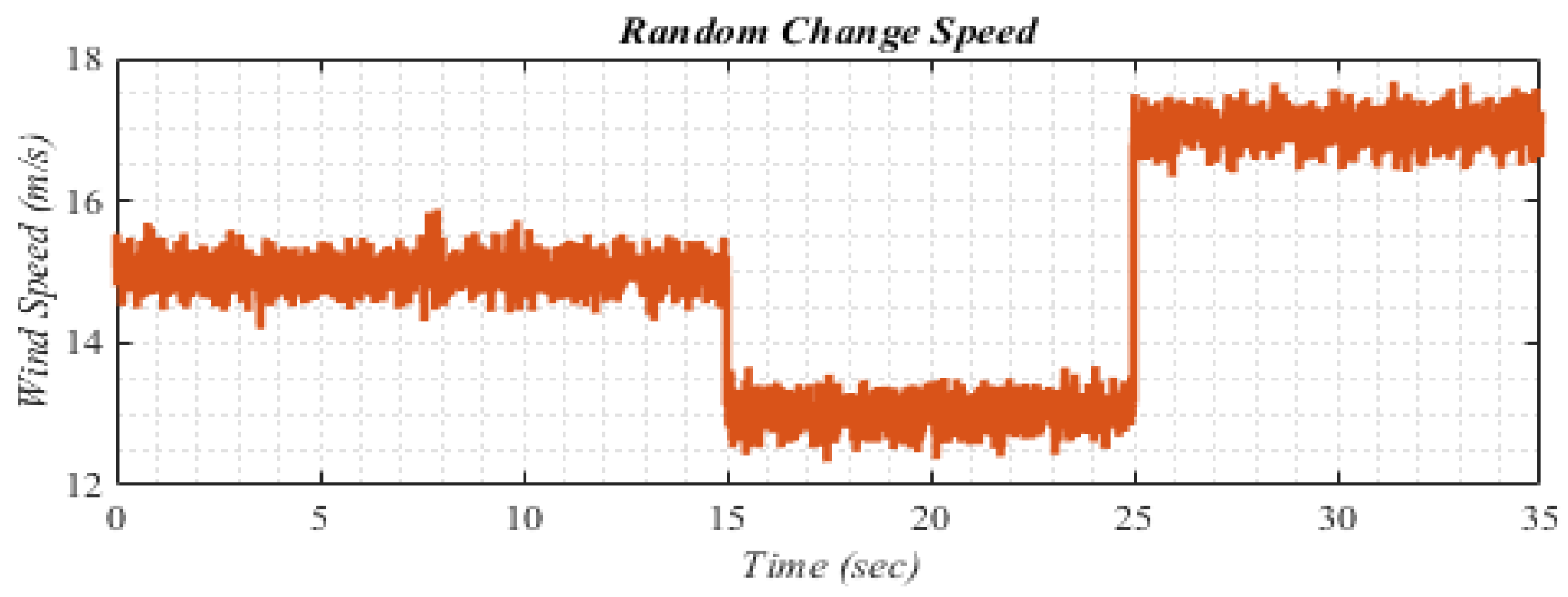
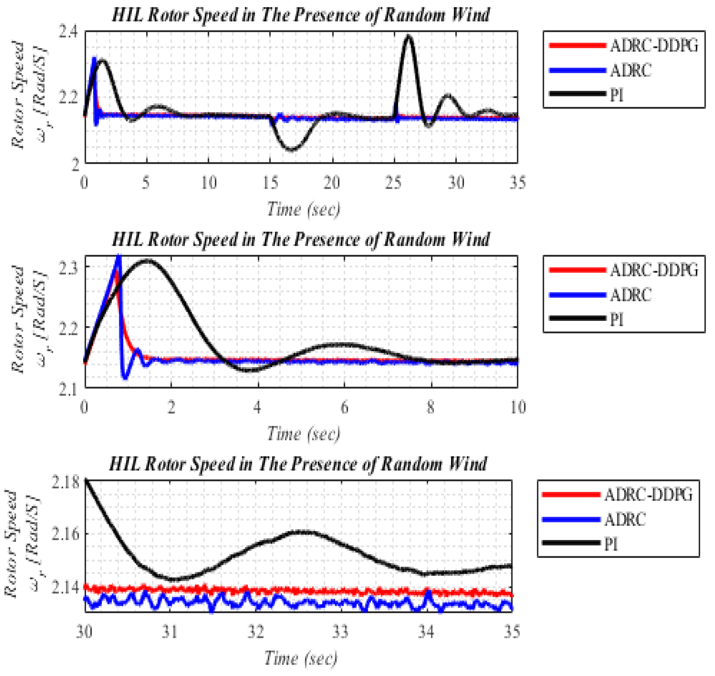
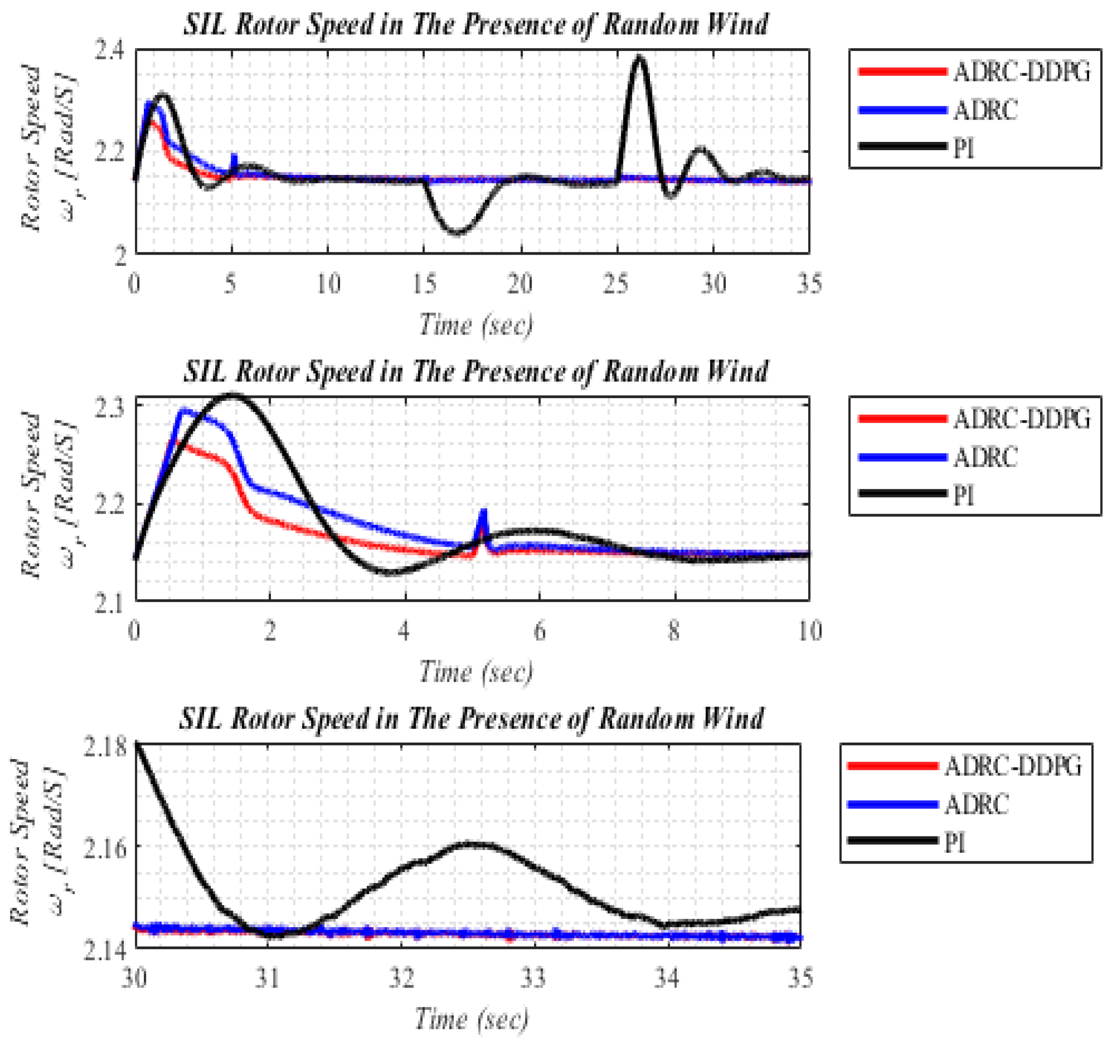
5.2. The Random Changes in wind Speed
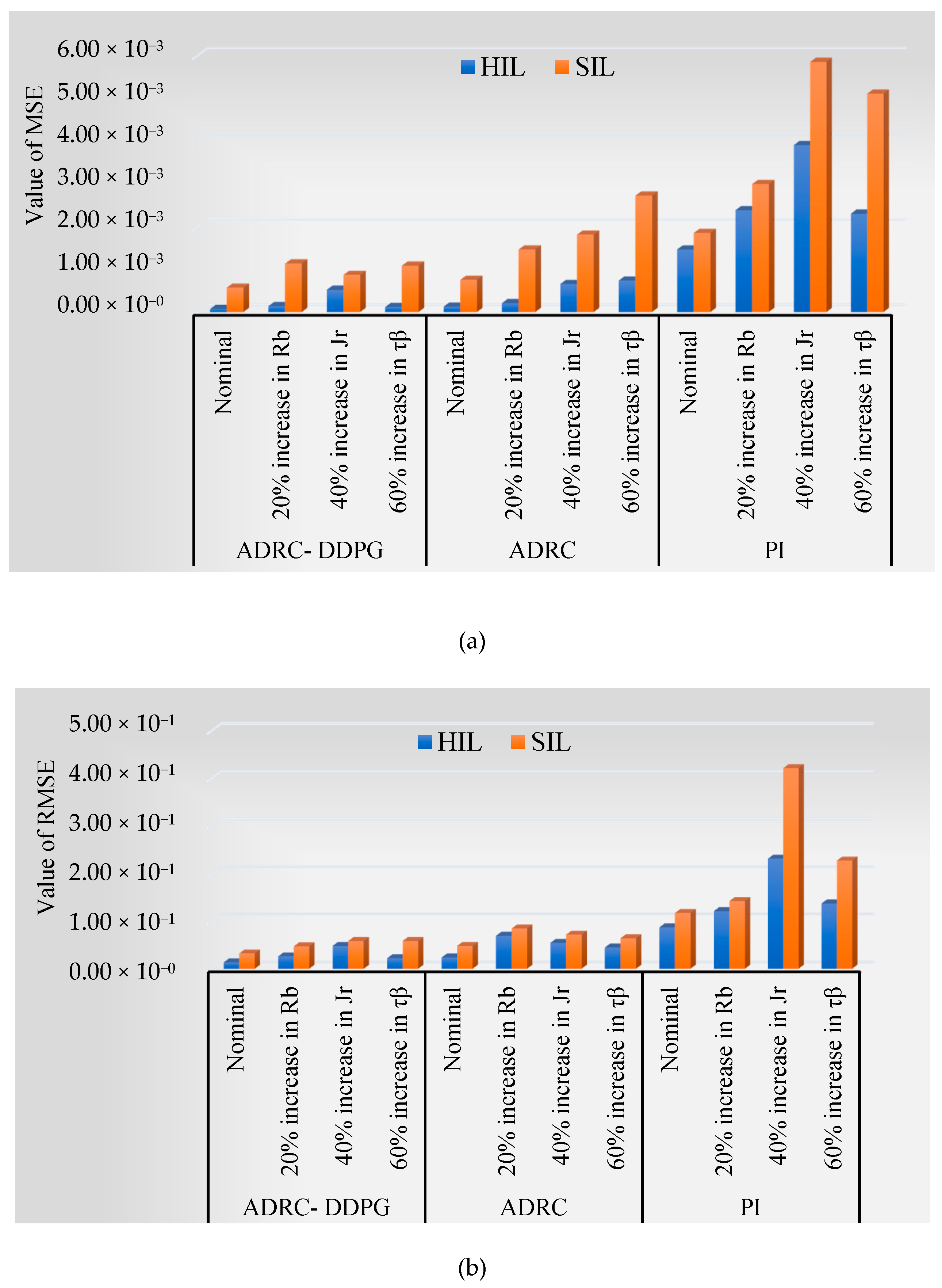
5.3. The Parametric Uncertainty in the Turbine Model
6. Conclusions
Author Contributions
Funding
Conflicts of Interest
References
- Dehghani, M.; Khooban, M.H.; Niknam, T.; Rafiei, S.M.R. Time-varying sliding mode control strategy for multibus low-voltage microgrids with parallel connected renewable power sources in islanding mode. J. Energy Eng. 2016, 142, 05016002. [Google Scholar] [CrossRef]
- Gheisarnejad, M.; Mohammadi-Moghadam, H.; Boudjadar, J.; Khooban, M.H. Active Power Sharing and Frequency Recovery Control in an Islanded Microgrid With Nonlinear Load and Nondispatchable DG. IEEE Syst. J. 2019, 14, 1058–1068. [Google Scholar] [CrossRef]
- Gao, Z.; Tang, C.; Zhou, X.; Ma, Y.; Wu, Y.; Yin, J.; Xu, X. An overview on development of wind power generation. In Proceedings of the 2016 Chinese Control and Decision Conference (CCDC), Yinchuan, China, 28–30 May 2016; pp. 435–439. [Google Scholar]
- Heydari-Doostabad, H.; Khalghani, M.R.; Khooban, M.H. A novel control system design to improve LVRT capability of fixed speed wind turbines using STATCOM in presence of voltage fault. Int. J. Electr. Power Energy Syst. 2016, 77, 280–286. [Google Scholar] [CrossRef]
- Mahdizadeh, A.; Schmid, R.; Oetomo, D. Fatigue load mitigation in multi-megawatt wind turbines using output regulation control. In Proceedings of the 2017 21st International Conference on System Theory, Control and Computing (ICSTCC), Sinaia, Romania, 19–21 October 2017; pp. 163–168. [Google Scholar]
- Erikstad, S.O. Merging Physics, Big Data Analytics and Simulation for the Next-Generation Digital Twins. Hiper, No. September; High-Performance Marine Vehicles: Zevenwacht, South-Africa, 2017; pp. 139–149. [Google Scholar]
- Wagg, D.J.; Gardner, P.; Barthorpe, R.J.; Worden, K. On Key Technologies for Realising Digital Twins for Structural Dynamics Applications. In Model Validation and Uncertainty Quantification, 2019 ed.; Springer: Berlin, Germany, 2020; Volume 3, pp. 267–272. [Google Scholar]
- Sivalingam, K.; Sepulveda, M.; Spring, M.; Davies, P. A review and methodology development for remaining useful life prediction of offshore fixed and floating wind turbine power converter with digital twin technology perspective. In Proceedings of the 2018 2nd International Conference on Green Energy and Applications (ICGEA), Singapore, 24–26 March 2018; pp. 197–204. [Google Scholar]
- Rezaei, V. Advanced control of wind turbines: Brief survey, categorization, and challenges. In Proceedings of the 2015 American Control Conference (ACC), Chicago, IL, USA, 1–3 July 2015; pp. 3044–3051. [Google Scholar]
- Gharibeh, H.F.; Khiavi, L.M.; Farrokhifar, M.; Alahyari, A.; Pozo, D. Capacity Value of Variable-Speed Wind Turbines. In Proceedings of the 2019 IEEE Milan PowerTech, Milan, Italy, 23–27 June 2019; pp. 1–5. [Google Scholar]
- Chen, J.; Chen, J.; Gong, C. New overall power control strategy for variable-speed fixed-pitch wind turbines within the whole wind velocity range. IEEE Trans. Ind. Electron. 2012, 60, 2652–2660. [Google Scholar] [CrossRef]
- Miao, L.; Wen, J.; Xie, H.; Yue, C.; Lee, W.-J. Coordinated control strategy of wind turbine generator and energy storage equipment for frequency support. IEEE Trans. Ind. Appl. 2015, 51, 2732–2742. [Google Scholar] [CrossRef]
- Xie, K.; Jiang, Z.; Li, W. Effect of wind speed on wind turbine power converter reliability. IEEE Trans. Energy Convers. 2012, 27, 96–104. [Google Scholar] [CrossRef]
- Anjun, X.; Hao, X.; Shuju, H.; Honghua, X. Pitch control of large scale wind turbine based on expert PID control. In Proceedings of the 2011 International Conference on Electronics, Communications and Control (ICECC), Ningbo, China, 9–11 September 2011; pp. 3836–3839. [Google Scholar]
- Kim, J.-S.; Jeon, J.; Heo, H. Design of adaptive PID for pitch control of large wind turbine generator. In Proceedings of the 2011 10th International Conference on Environment and Electrical Engineering, Rome, Italy, 8–11 May 2011; pp. 1–4. [Google Scholar]
- Cheng, X.; Lei, Z.; Junqiu, Y. Fuzzy PID controller for wind turbines. In Proceedings of the 2009 Second International Conference on Intelligent Networks and Intelligent Systems, Tianjin, China, 1–3 November 2009; pp. 74–77. [Google Scholar]
- Baburajan, S. Improving the efficiency of a wind turbine system using a fuzzy-pid controller. In Proceedings of the 2018 Advances in Science and Engineering Technology International Conferences (ASET), Dubai, Sharjah, 6 February–5 April 2018; pp. 1–5. [Google Scholar]
- Bakka, T.; Karimi, H.-R.; Christiansen, S. Linear parameter-varying modelling and control of an offshore wind turbine with constrained information. IET Control Theory Appl. 2014, 8, 22–29. [Google Scholar] [CrossRef]
- Boukhezzar, B.; Siguerdidjane, H. Nonlinear control of a variable-speed wind turbine using a two-mass model. IEEE Trans. Energy Convers. 2010, 26, 149–162. [Google Scholar] [CrossRef]
- Ma, Z.; Yan, Z.; Shaltout, M.L.; Chen, D. Optimal real-time control of wind turbine during partial load operation. IEEE Trans. Control Syst. Technol. 2015, 23, 2216–2226. [Google Scholar] [CrossRef]
- da Costa, J.P.; Pinheiro, H.; Degner, T.; Arnold, G. Robust controller for DFIGs of grid-connected wind turbines. IEEE Trans. Ind. Electron. 2010, 58, 4023–4038. [Google Scholar] [CrossRef]
- Beltran, B.; Ahmed-Ali, T.; Benbouzid, M.E. Sliding mode power control of variable-speed wind energy conversion systems. IEEE Trans. Energy Convers. 2008, 23, 551–558. [Google Scholar] [CrossRef] [Green Version]
- Dang, D.; Wang, Y.; Cai, W. Offset-free predictive control for variable speed wind turbines. IEEE Trans. Sustain. Energy 2012, 4, 2–10. [Google Scholar] [CrossRef]
- Civelek, Z.; Lüy, M.; Çam, E.; Barışçı, N. Control of pitch angle of wind turbine by fuzzy PID controller. Intell. Autom. Soft Comput. 2016, 22, 463–471. [Google Scholar] [CrossRef]
- Henriksen, L.C. Model Predictive Control of Wind Turbines. Ph.D. Thesis, Technical Universityof Denmark, Kgs. Lyngby, Denmark, 2011. [Google Scholar]
- Kachroo, P. Existence of solutions to a class of nonlinear convergent chattering-free sliding mode control systems. IEEE Trans. Autom. Control 1999, 44, 1620–1624. [Google Scholar] [CrossRef] [Green Version]
- Kachroo, P.; Tomizuka, M. Chattering reduction and error convergence in the sliding-mode control of a class of nonlinear systems. IEEE Trans. Autom. Control 1996, 41, 1063–1068. [Google Scholar] [CrossRef] [Green Version]
- Li, S.; Cao, M.; Li, J.; Cao, J.; Lin, Z. Sensorless-Based Active Disturbance Rejection Control for a Wind Energy Conversion System With Permanent Magnet Synchronous Generator. IEEE Access 2019, 7, 122663–122674. [Google Scholar] [CrossRef]
- Li, S.; Li, J. Output predictor-based active disturbance rejection control for a wind energy conversion system with PMSG. IEEE Access 2017, 5, 5205–5214. [Google Scholar] [CrossRef]
- Kourchi, M.; Rachdy, A. Nonlinear ADRC Applied on Wind Turbine Based on DFIG Operating at its Partial Load. In Proceedings of the 2019 International Conference of Computer Science and Renewable Energies (ICCSRE), Agadir, Morocco, 22–24 July 2019; pp. 1–8. [Google Scholar]
- Anjun, X.; Xu, L.; Shuju, H.; Nianhong, L.; Honghua, X. A new pitch control method for large scale wind turbine based on ADRC. In Proceedings of the 2013 International Conference on Materials for Renewable Energy and Environment, Chengdou, China, 19–21 August 2014; pp. 373–376. [Google Scholar]
- Huang, C.; Yin, Y. Wind Turbine Pitch Control Based on Error-based ADRC Approach Optimized by Brain Storm Optimization Algorithm. In Proceedings of the 2019 1st International Conference on Industrial Artificial Intelligence (IAI), Shenyang, China, 23–27 July 2019; pp. 1–6. [Google Scholar]
- Khooban, M.H.; Soltanpour, R.M. Swarm optimization tuned fuzzy sliding mode control design for a class of nonlinear systems in presence of uncertainties. J. Intell. Fuzzy Syst. 2013, 24, 383–394. [Google Scholar] [CrossRef]
- Rahimi, A.; Bavafa, F.; Aghababaei, S.; Khooban, M.H.; Naghavi, S.V. The online parameter identification of chaotic behaviour in permanent magnet synchronous motor by self-adaptive learning bat-inspired algorithm. Int. J. Electr. Power Energy Syst. 2016, 78, 285–291. [Google Scholar] [CrossRef]
- Wiering, M.A.; van Hasselt, H. Ensemble algorithms in reinforcement learning. IEEE Trans. Syst. Man Cybern. Part B 2008, 38, 930–936. [Google Scholar] [CrossRef] [Green Version]
- Arvind, C.; Senthilnath, J. Autonomous RL: Autonomous Vehicle Obstacle Avoidance in a Dynamic Environment using MLP-SARSA Reinforcement Learning. In Proceedings of the 2019 IEEE 5th International Conference on Mechatronics System and Robots (ICMSR), Singapore, 3–5 May 2019; pp. 120–124. [Google Scholar]
- Hu, Y.; Li, W.; Xu, K.; Zahid, T.; Qin, F.; Li, C. Energy management strategy for a hybrid electric vehicle based on deep reinforcement learning. Appl. Sci. 2018, 8, 187. [Google Scholar] [CrossRef] [Green Version]
- Hasanvand, S.; Rafiei, M.; Gheisarnejad, M.; Khooban, M.-H. Reliable Power Scheduling of an Emission-Free Ship: Multi-Objective Deep Reinforcement Learning. IEEE Trans. Transp. Electrif. 2020. [Google Scholar] [CrossRef]
- Qiu, C.; Hu, Y.; Chen, Y.; Zeng, B. Deep Deterministic Policy Gradient (DDPG)-Based Energy Harvesting Wireless Communications. IEEE Internet Things J. 2019, 6, 8577–8588. [Google Scholar] [CrossRef]
- Khooban, M.H.; Gheisarnejad, M. A Novel Deep Reinforcement Learning Controller Based Type-II Fuzzy System: Frequency Regulation in Microgrids. IEEE Trans. Emerg. Top. Comput. Intell. 2020. [Google Scholar] [CrossRef]
- Gheisarnejad, M.; Khooban, M.H. An Intelligent Non-integer PID Controller-based Deep Reinforcement Learning: Implementation and Experimental Results. IEEE Trans. Ind. Electron. 2020. [Google Scholar] [CrossRef]
- Rodriguez-Ramos, A.; Sampedro, C.; Bavle, H.; De La Puente, P.; Campoy, P. A deep reinforcement learning strategy for UAV autonomous landing on a moving platform. J. Intell. Robot. Syst. 2019, 93, 351–366. [Google Scholar] [CrossRef]
- Ren, Y.; Li, L.; Brindley, J.; Jiang, L. Nonlinear PI control for variable pitch wind turbine. Control Eng. Pract. 2016, 50, 84–94. [Google Scholar] [CrossRef] [Green Version]
- Gu, S.; Lillicrap, T.; Sutskever, I.; Levine, S. Continuous deep q-learning with model-based acceleration. In Proceedings of the International Conference on Machine Learning, New York, NY, USA, 19–24 June 2016; pp. 2829–2838. [Google Scholar]
- Zhu, M.; Wang, X.; Wang, Y. Human-like autonomous car-following model with deep reinforcement learning. Transp. Res. Part C Emerg. Technol. 2018, 97, 348–368. [Google Scholar] [CrossRef] [Green Version]
- Li, F.; Jiang, Q.; Quan, W.; Cai, S.; Song, R.; Li, Y. Manipulation Skill Acquisition for Robotic Assembly Based on Multi-Modal Information Description. IEEE Access 2019, 8, 6282–6294. [Google Scholar] [CrossRef]
- Khooban, M.H. Hardware-in-the-loop simulation for the analyzing of smart speed control in highly nonlinear hybrid electric vehicle. Trans. Inst. Meas. Control 2019, 41, 458–467. [Google Scholar] [CrossRef]
- Khooban, M.-H.; Dehghani, M.; Dragičević, T. Hardware-in-the-loop simulation for the testing of smart control in grid-connected solar power generation systems. Int. J. Comput. Appl. Technol. 2018, 58, 116–128. [Google Scholar] [CrossRef]


| Performance Measurements | ADRC-DDPG | ADRC | PI | |||
|---|---|---|---|---|---|---|
| HIL | SIL | HIL | SIL | HIL | SIL | |
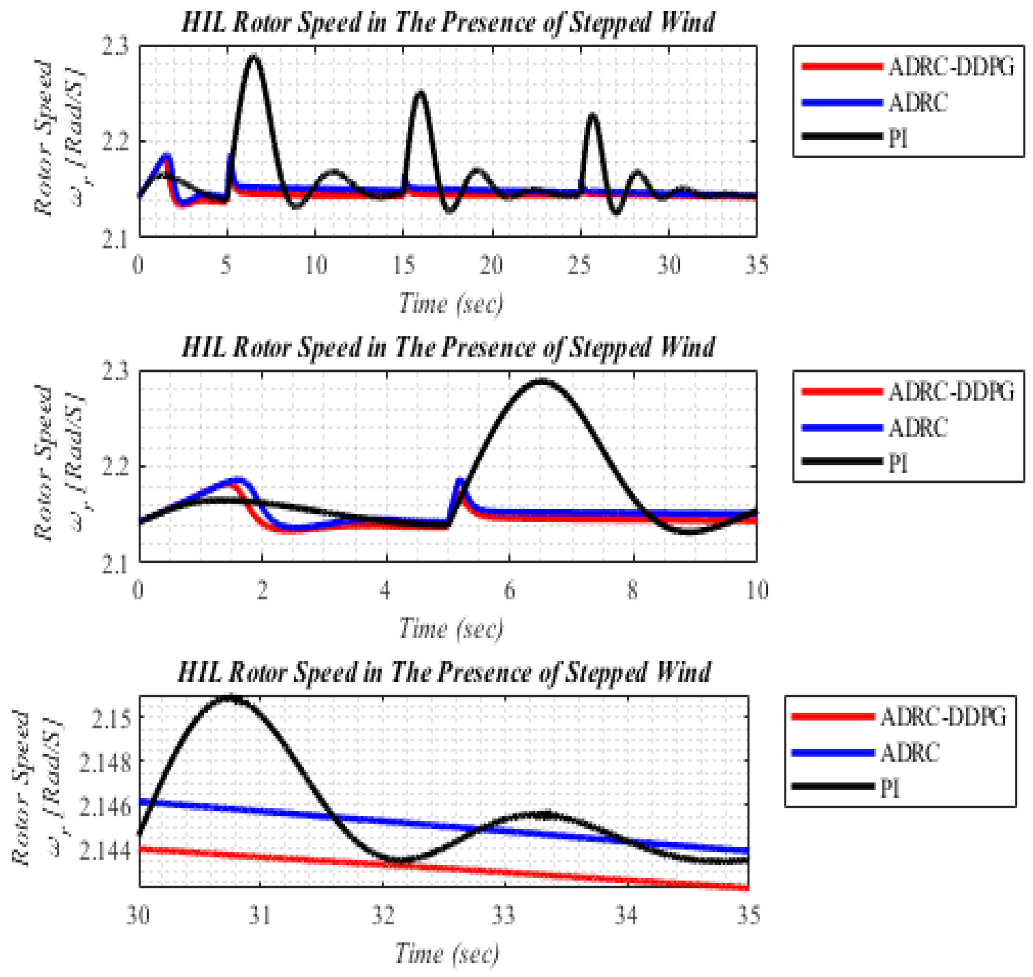
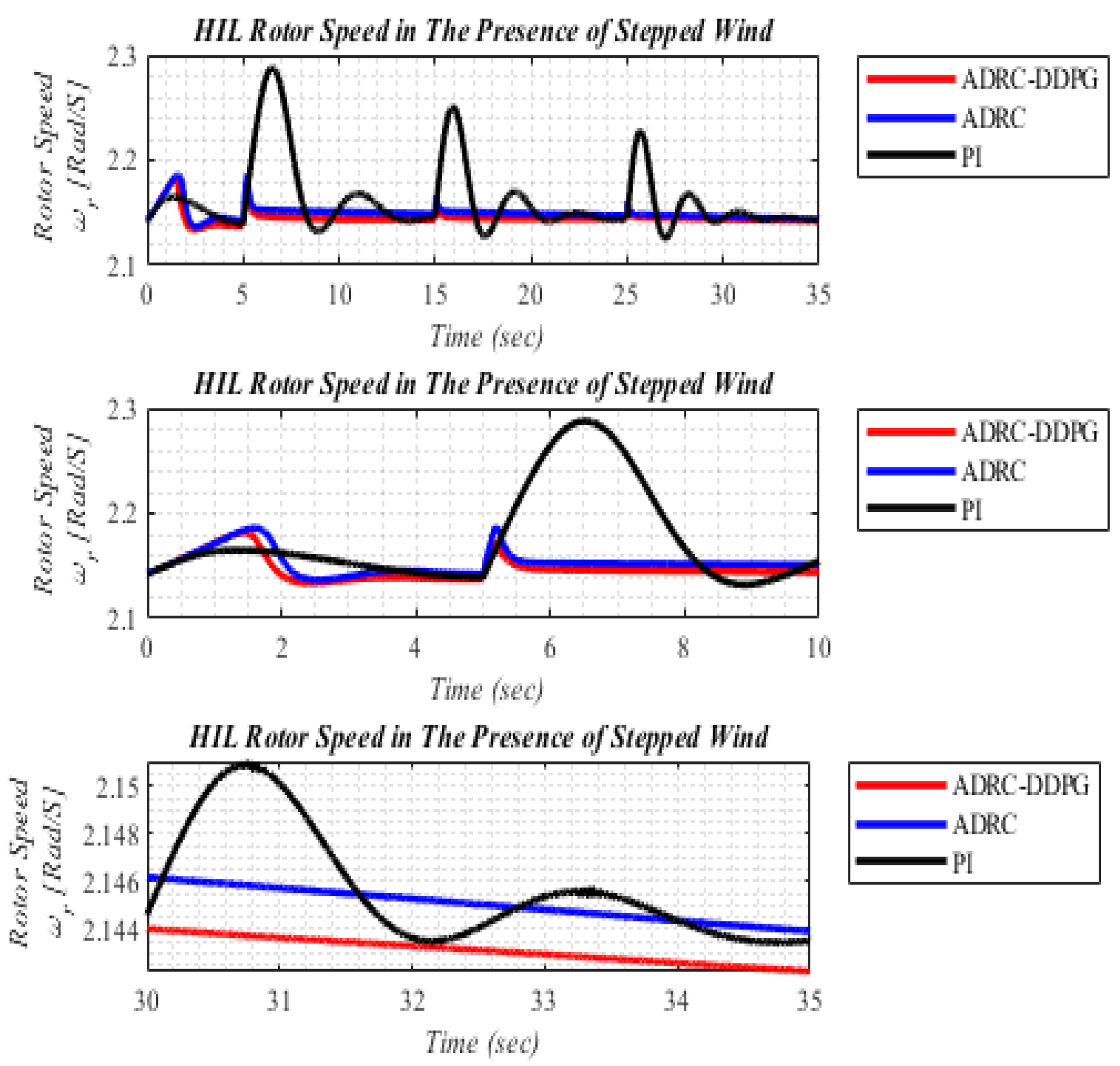
| Settling time | 2.1 | 2.3 | 5.2 | 5.8 | 27 | 29 |
| Overshoot | 1.78% | 3.13% | 2.10% | 5.00% | 5.93% | 6.86% |
| Error | 0.6577 | 0.7143 | 0.9315 | 1.0875 | 16.5921 | 17.3392 |
© 2020 by the authors. Licensee MDPI, Basel, Switzerland. This article is an open access article distributed under the terms and conditions of the Creative Commons Attribution (CC BY) license (http://creativecommons.org/licenses/by/4.0/).
Share and Cite
Jahanshahi Zeitouni, M.; Parvaresh, A.; Abrazeh, S.; Mohseni, S.-R.; Gheisarnejad, M.; Khooban, M.-H. Digital Twins-Assisted Design of Next-Generation Advanced Controllers for Power Systems and Electronics: Wind Turbine as a Case Study. Inventions 2020, 5, 19. https://doi.org/10.3390/inventions5020019
Jahanshahi Zeitouni M, Parvaresh A, Abrazeh S, Mohseni S-R, Gheisarnejad M, Khooban M-H. Digital Twins-Assisted Design of Next-Generation Advanced Controllers for Power Systems and Electronics: Wind Turbine as a Case Study. Inventions. 2020; 5(2):19. https://doi.org/10.3390/inventions5020019
Chicago/Turabian StyleJahanshahi Zeitouni, Meisam, Ahmad Parvaresh, Saber Abrazeh, Saeid-Reza Mohseni, Meysam Gheisarnejad, and Mohammad-Hassan Khooban. 2020. "Digital Twins-Assisted Design of Next-Generation Advanced Controllers for Power Systems and Electronics: Wind Turbine as a Case Study" Inventions 5, no. 2: 19. https://doi.org/10.3390/inventions5020019