Article

Flywheel vs. Supercapacitor as Wayside Energy Storage for Electric Rail Transit Systems

by
Mahdiyeh Khodaparastan
1,* and
Ahmed Mohamed
1,2,*
1
Electrical Engineering Department, Grove School of Engineering, City University of New York, City College, New York, NY 10017, USA
2
Department of Electrical Engineering, Faculty of Engineering, Minia University, Minia 61512, Egypt
*
Authors to whom correspondence should be addressed.
Inventions 2019, 4(4), 62; https://doi.org/10.3390/inventions4040062
Submission received: 13 June 2019 / Revised: 18 September 2019 / Accepted: 19 September 2019 / Published: 10 October 2019

Abstract

:
Energy storage technologies are developing rapidly, and their application in different industrial sectors is increasing considerably. Electric rail transit systems use energy storage for different applications, including peak demand reduction, voltage regulation, and energy saving through recuperating regenerative braking energy. In this paper, a comprehensive review of supercapacitors and flywheels is presented. Both are compared based on their general characteristics and performances, with a focus on their roles in electric transit systems when used for energy saving, peak demand reduction, and voltage regulation. A cost analysis is also included to provide initial guidelines on the selection of the appropriate technology for a given transit system.

Graphical Abstract

1. Introduction

Electric rail transit systems are continuously developing, in order to provide fast and reliable services to their ever-increasing customers. A critical challenge for electric rail transit systems is the recuperation of regenerative braking energy. Regenerative braking energy is the energy produced by trains during deceleration. In other words, it is the energy mechanically stored in the rotor inertia, which can be converted back into electricity and injected into the rail during deceleration [1]. One possible solution of recuperating regenerative braking energy is through the installation of energy storage systems (ESS) next to the third rail (the power rail next to the running rail). ESS would capture this energy and later release it, when needed. Typical applications of recuperated energy include energy saving, peak demand reduction, and voltage regulation [2]. Different ESS technologies have been proposed and implemented in rail transit systems worldwide. For instance, a flywheel was installed in the Los Angeles Metro for energy saving, and a supercapacitor was installed in several European countries for energy saving and voltage regulation [3]. A sodium-sulfur (NA-s) battery was used in the Long Island railroad, and a Li-ion battery was used in the Philadelphia transit system [4]. Among these technologies, flywheel and supercapacitors show superior characteristics and performances, compared to other available technologies, in terms of power capacity and charge/discharge time.
In this paper, we investigated these two technologies and their applications in electric rail transit systems. A portion of a DC electric rail transit system was modeled in MATLAB/Simulink. The energy storage system was installed in a specific substation, and the performance of these two technologies in providing services, including peak demand reduction and voltage regulation, was tested and compared.
The rest of this paper is organized as follows: 
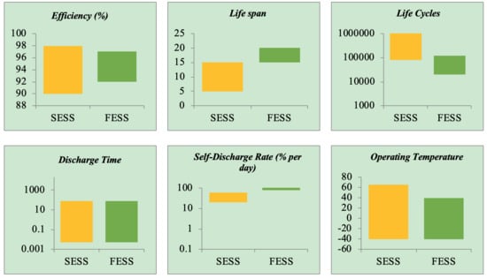
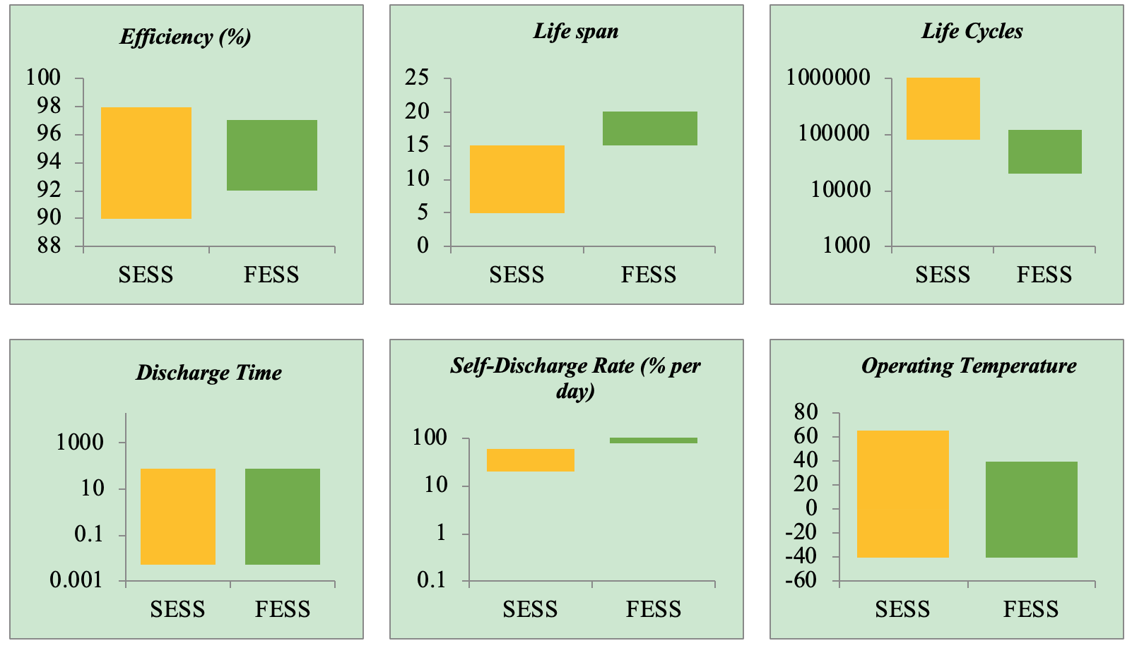
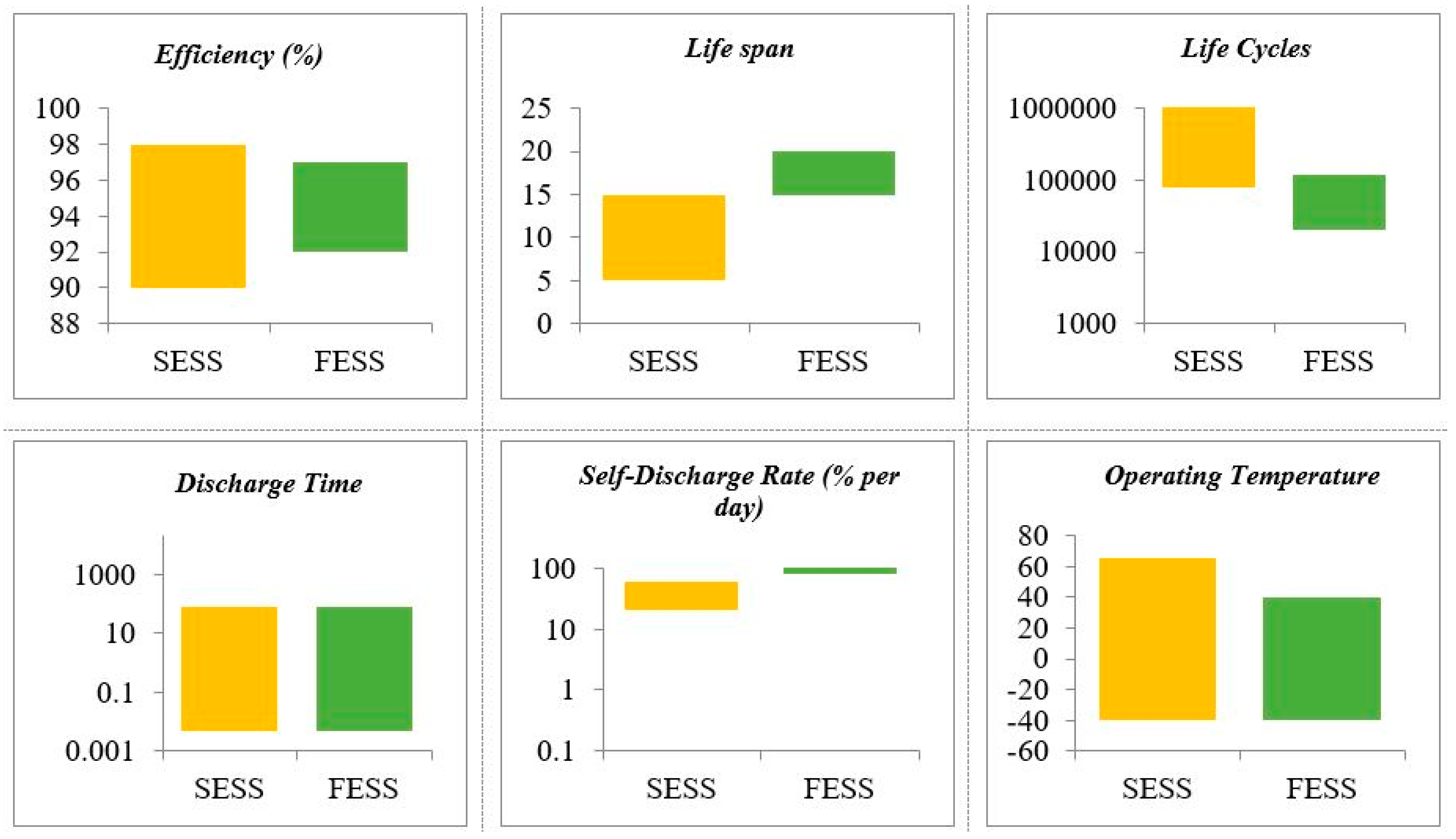
Section 2 describes flywheel energy storage (FESS) and supercapacitor energy storage (SESS), and compares their general characteristics. Section 3 presents a description of an electric rail transit system that was used as a case study in this paper. Section 4 presents case study and simulation results. Section 4.3 presents a cost analysis. Finally, Section 5 presents the conclusion.

2. Energy Storage Technologies

In this section, flywheel and supercapacitor technologies are described, and their general characteristics are compared.

2.1. Flywheel

Generally, a flywheel energy storage system consists of a rotating mass, a motor/generator set, bearings, containment, and a power electronic converter, as presented in Figure 1.
Flywheel energy storages are classified into two main groups: low-speed (rotation speed below 10,000 rpm) and high-speed (rotation speed above 10,000 rpm). Low-speed flywheels are generally made of a metal rotor; and a mechanical, or combination of metal and magnetic, bearing. They have been commercially available for a long time and are mainly used for power quality enhancement. On the other hand, high-speed flywheels are made of a composite rotor and magnetic bearing. They are currently the focus of industrial and academic research and development. There are some commercially available examples of high-speed flywheels [5,6]. For instance, flywheels produced by VYCON Energy and Beacon Power are reported in the literature [7,8].
Flywheels store energy mechanically in a rotating mass. During the charging process, they speed up the rotating mass and slow it down during the discharging process. The amount of energy stored in a flywheel depends on the rotating mass inertia (J) and the speed of rotation (ω), as follows:
E = 1 2 J ω 2
The operating speed of the flywheel is limited between ωmin and ωmax to avoid excessive voltage variation, and to limit the maximum torque applied to the electric machine [9]. The power of a flywheel is presented as follows:
P = T ω
where T is the torque and ω is the speed of rotation. The amount of power that can be released by a flywheel depends on the rating of the machine and the power electronic interface.
The conversion of the energy (kinetic to electrical and vice versa) was accomplished using an electric machine. Different types of electric machines can be used in flywheel systems, such as the induction machine, permanent magnet synchronous machine, switched reluctance machine, and synchronous homo-polar machine [5].
To connect a flywheel to the grid, a power electronic converter is needed to control the operation of the machine and the power exchange between the grid and the FESS. Varieties of power electronic interfaces exist for interconnecting FESS. They are selected based on parameters, including the speed of rotation, electrical loading (AC or DC), response time, the need for high power or high energy, and parallel or series connection [10].
Flywheel energy storage is a strong candidate for applications that require high power for the release of a large amount of energy in a short time (typically a few seconds) with frequent charge and discharge cycles. These applications include grid application (frequency regulation and short-time power quality services), uninterruptable power supply (UPS), electric vehicle, rail transportation, and aerospace [5,10,11,12]. Examples of the application of flywheel energy storage in electric rail transit systems are presented in Table 1. It is worth mentioning that each project may have used different methods for energy saving.

2.2. Supercapacitor

Supercapacitor is a general expression for a group of electrochemical capacitors, including pseudo capacitors, electrochemical double layer capacitors (EDLC), and hybrid capacitors [17]. The main difference between these groups of capacitors is the energy storage principle. For instance, pseudo capacitors use a mechanism called ‘faradic’, in which electric charges are transferred between the electrodes and the electrolyte. The EDLC type uses a non-faradic mechanism, in which no chemical reaction happens to transfer the charges between the electrodes and electrolyte. Hybrid capacitors use both faradic and non-faradic mechanisms [18,19,20].
The focus of this paper is on EDLC type capacitors. However, the word supercapacitor is used interchangeably with EDLC. Mostly, EDLC consists of two porous electrodes immersed in an electrochemical solution. A schematic of the supercapacitor energy storage system is presented in Figure 2. As illustrated, when voltage is applied to the electrodes, they absorb ions with opposite charges available in the electrolyte, and create a layer called the stern layer next to the electrodes. Electrodes also absorb some of the ions by Coulomb force. These ions create another layer called the diffuse layer near the surface of the electrode. This phenomenon is known as the double layer effect [5].
A general formula for a capacitor is presented as follows:
C = ε 0 ε r A d
The same equation can be considered for supercapacitors. However, because of the porous characteristics of the electrode, the overall surface area of the capacitor (A) is significantly larger. On the other hand, the distance between the two electrodes (d) is in the nm scale. Therefore, the capacity of the supercapacitors grows much larger than conventional capacitors. This feature leads to an important characteristic, which is the high energy storing capability. The energy stored in the supercapacitor is presented as follows:
E = 1 2 C V 2
Since a supercapacitor stores energy electrostatically, it can charge and discharge very quickly with minimal efficiency degradation. Supercapacitors also have high power capacity. Because of the special material (carbon, for example) used as an electrolyte, the equivalent resistance of a supercapacitor (ESR) is much lower than conventional capacitors. Assuming the supercapacitor voltage is limited to 50% of its rated value, the supercapacitor power is presented as follows:
P max = 1 4 V 2 E S R
Supercapacitor applications range from large scale grid applications to electric vehicles and small-scale applications, and are commonly used in electric rail transit systems. Examples of its application in electric rail transit systems are presented in Table 2.

2.3. Characteristic Comparisons

In this section, the general characteristics of flywheels and supercapacitors are compared. Table 3 shows the power and energy characteristics of these technologies [25,26,27].
A supercapacitor has less kW and Wh per unit weight. Supercapacitors may have a smaller MW per unit volume. However, a flywheel may have a smaller energy density per unit volume.
Figure 3 shows the characteristics of these technologies in terms of efficiency, lifespan, life-cycle, discharge time at rated power, self-discharge rate, and operating temperature. As illustrated, both technologies show promising characteristics in terms of efficiency (both above 90%). They also show similar characteristics in discharge times (both can discharge fast). However, the flywheel has a significantly larger life cycle (between 800,000–1,000,000 cycles) than the supercapacitor (20,000–100,000 cycles). In addition, in terms of life span, the flywheel shows superior characteristics (around 20 years) compared to the supercapacitor (between 5 and 15 years). On the other hand, supercapacitors have superior characteristics in terms of daily self-discharge rate and operating temperature compared to the flywheel.
Other parameters that need to be compared include safety and environmental impacts. The most conspicuous safety issue of flywheel energy storage is rotor failure, due to the propagation of cracks over time. In such a case, a large fragment of the flywheel rotor can break apart during rotation. Having a large metal containment can prevent such a problem. In terms of environmental impact, flywheels produce heat and noise during operation. Using active cooling systems and deploying flywheels underground can considerably minimize these two problems.
For supercapacitors, there are minimal safety and environmental issues during normal conditions; however, if a supercapacitor’s sealed containment is damaged, toxic materials may be released causing health issues. Additionally, the internal components of supercapacitors are combustible, and if a particular failure mode occurs, or if they are exposed to direct fire or an ignition source, they can decompose and produce toxic gases [13].

3. System under Study

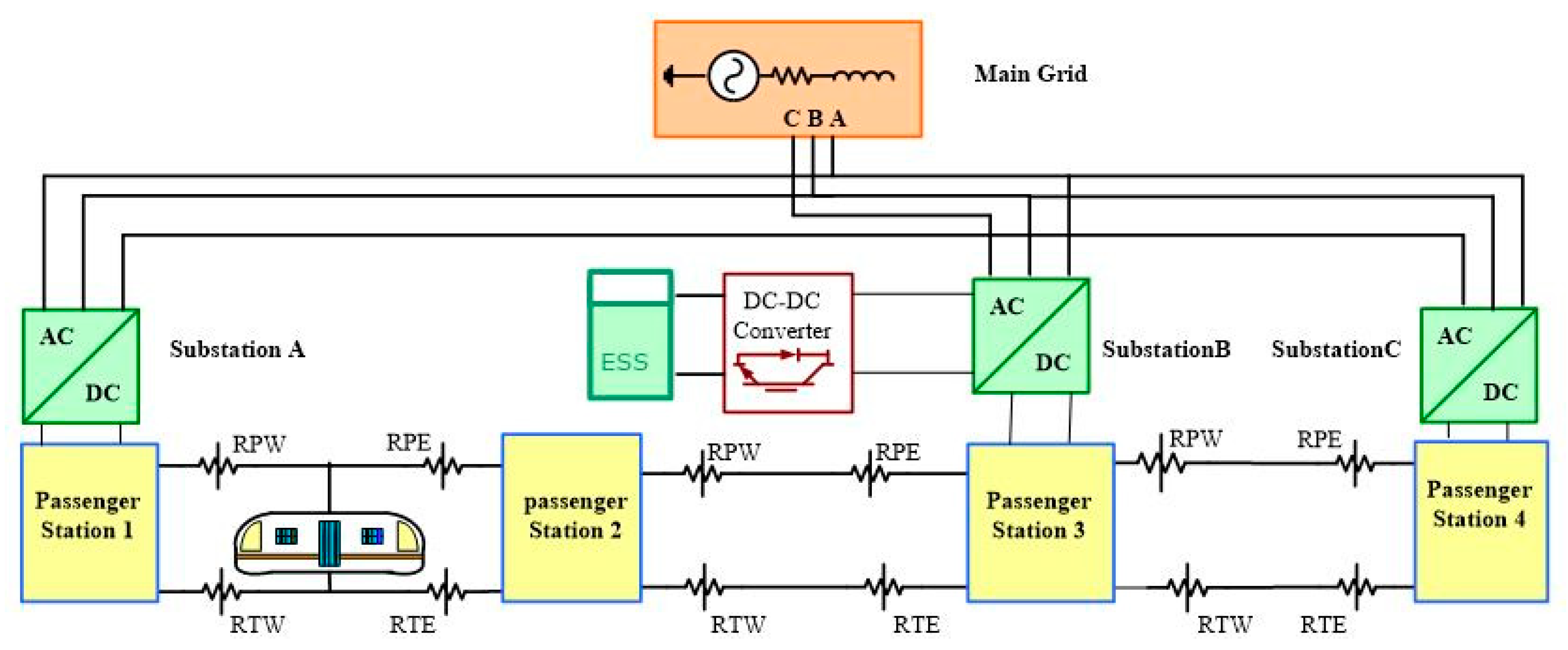
To investigate the performance of FESS and SESS in the electric rail transit system, a portion of an electric rail transit system, including four passenger stations and three substations, was selected and simulated in the MATLAB/Simulink environment. A schematic of the system under study is presented in Figure 4.
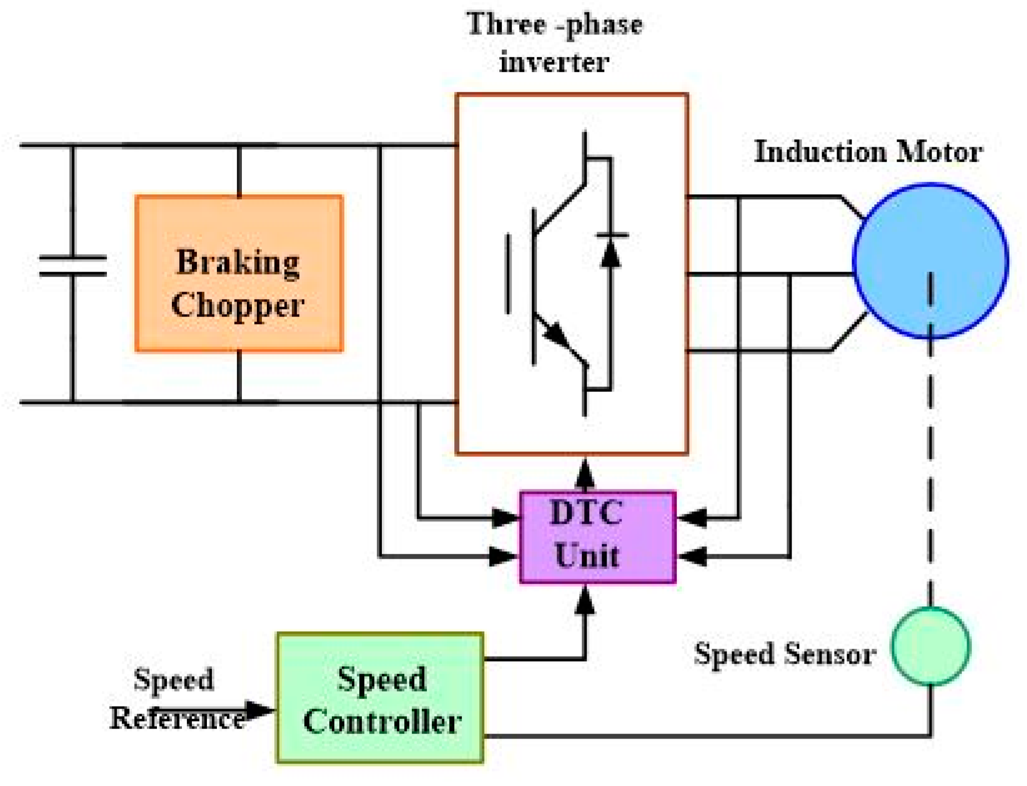
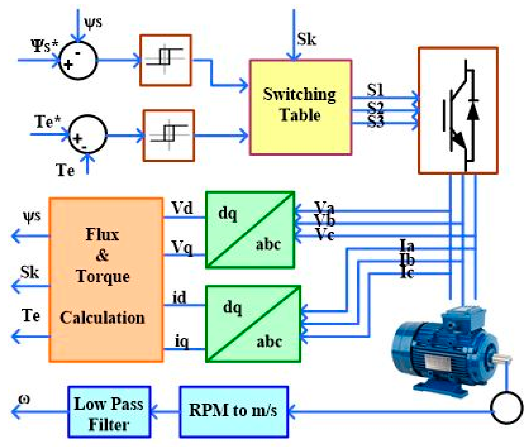
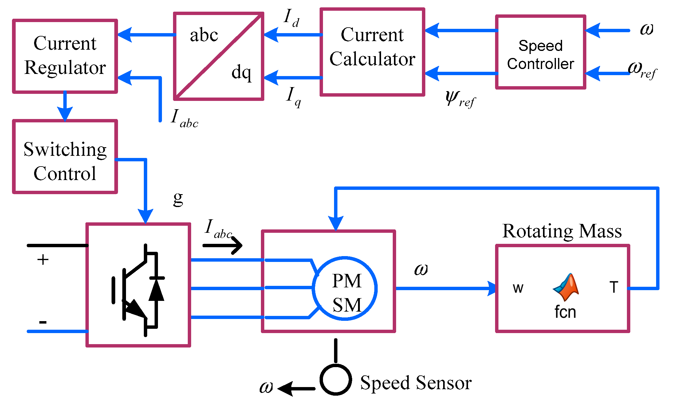
In this system, substations consisted of two parallel sets of transformers and unidirectional converters, which were responsible for converting the AC voltage (13 kV) from the utility grid to the DC voltage (650 V) desired by the transit system. Power and traction rails were modeled by variable resistors to represent train movement; their values changed based on the train position. A train was assumed to be moving from passenger station 1 to passenger station 4. Trains were modeled using a backward modeling approach. In this approach, the speed of the wheel was used as an input to the model using vehicle dynamic equations (Equations (6)–(11)), and the required torque and the angular speed from the gearbox was calculated. Using gearbox equations (Equations (12)–(14)), the required torque and speed from the motor drive was calculated. The schematic of the electric drive and its controller is presented in Figure 5 and Figure 6, respectively. Using an electric drive motor, the power consumed by the train for each specific speed profile can be calculated as:
F T F R F g F W = M M e t r o d v d t
F R = f R M M e t r o g c o s θ
F g = M M e t r o g s i n θ
F W = 1 2 C w A ρ v 2
T w = F T × r 4 n c a r s
ω W = v r
T G = T w γ G + B γ G
ω G = ω w γ G
B = T w ( 1 η G )
where FR, FW, and Fg are the friction force, the force due to the wind, and the gravity force, respectively; which could be overcome by the tractive effort (FT) produced by the electric drives in each car. Tw and ωw are the required torque and angular speed of the wheel. Mmetro is the weight of the train; fR is the friction factor; g is the acceleration gravity; and Cw, A, and γ are drag coefficient, the front area of the train, and air density, respectively. The velocity dependent part of the running resistance was considered in the rolling resistance coefficient. The number of cars and the radius of the wheels are presented by n and r, respectively. TG and ωG are the torque and the speed of the gearbox. ηG is the gearbox efficiency, γG is the gearbox ratio, and B represents the vehicle losses.
A train consisted of several connected cars, and each car had one or two electric drives that controlled the torque and the speed of the wheels, as presented in Figure 5. The model used in this paper was validated using real data from the New York City subway system. More information on system simulation can be found in the literature [14,15].
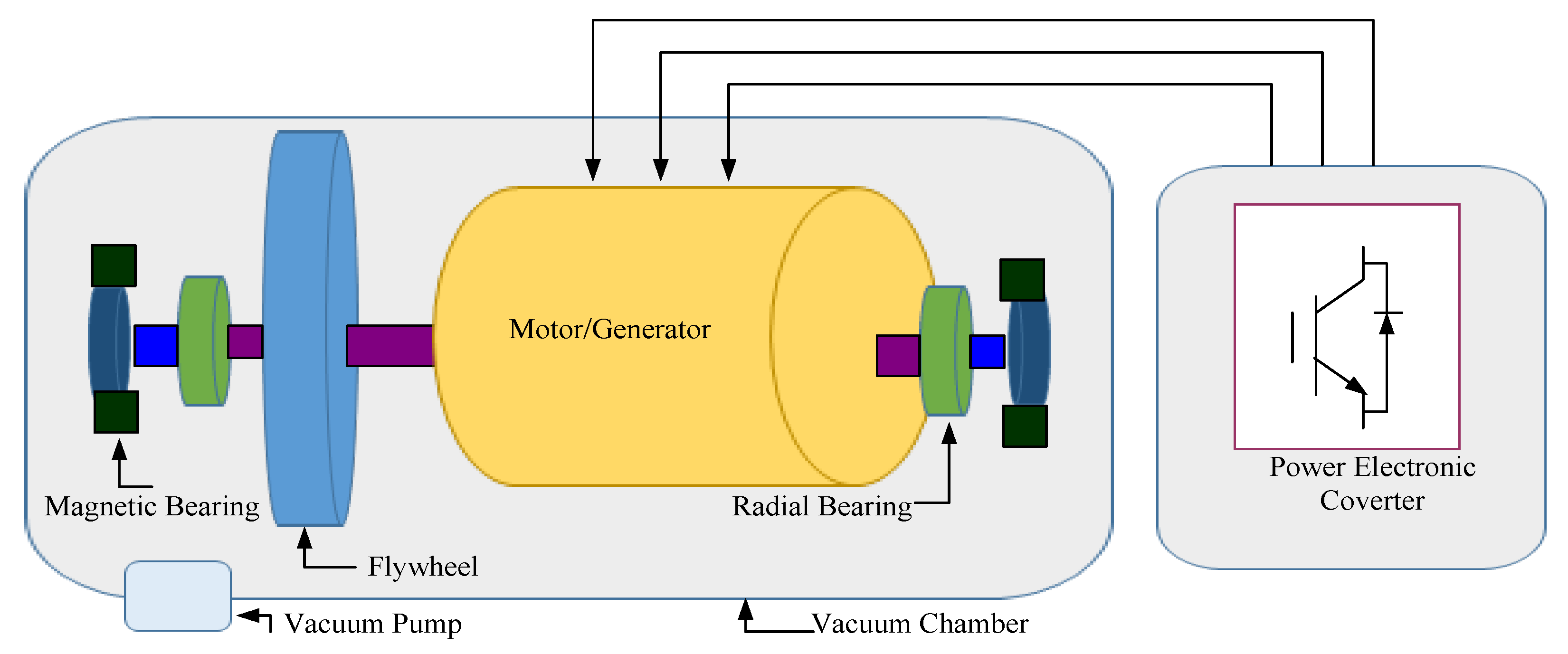
FESS and SESS were placed in the middle substation (substation B) to provide voltage regulation and peak demand reduction during the transit rush hours. The flywheel was modeled by additional inertia added to the permanent magnet synchronous machine, as presented in Figure 7 [15].
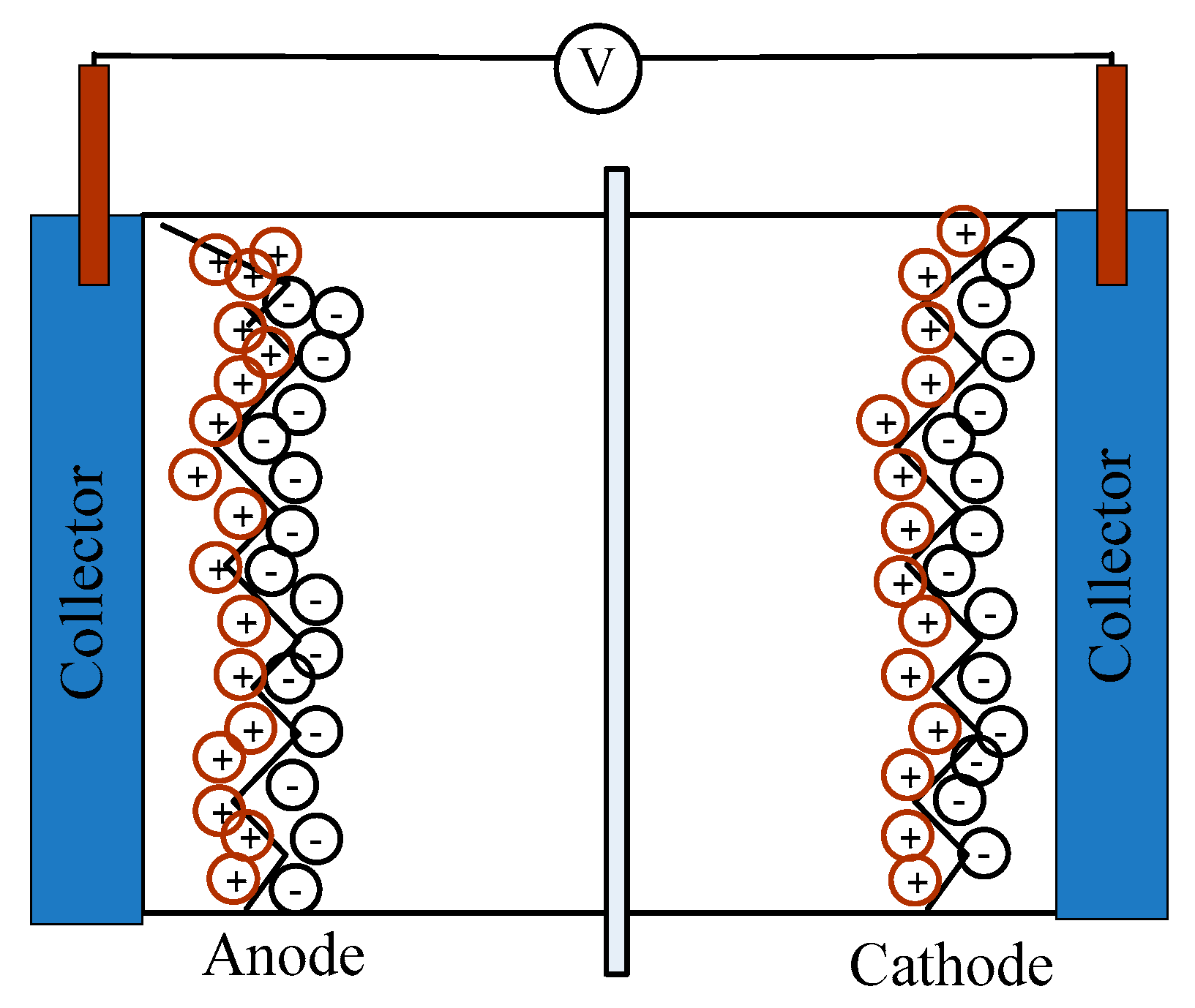
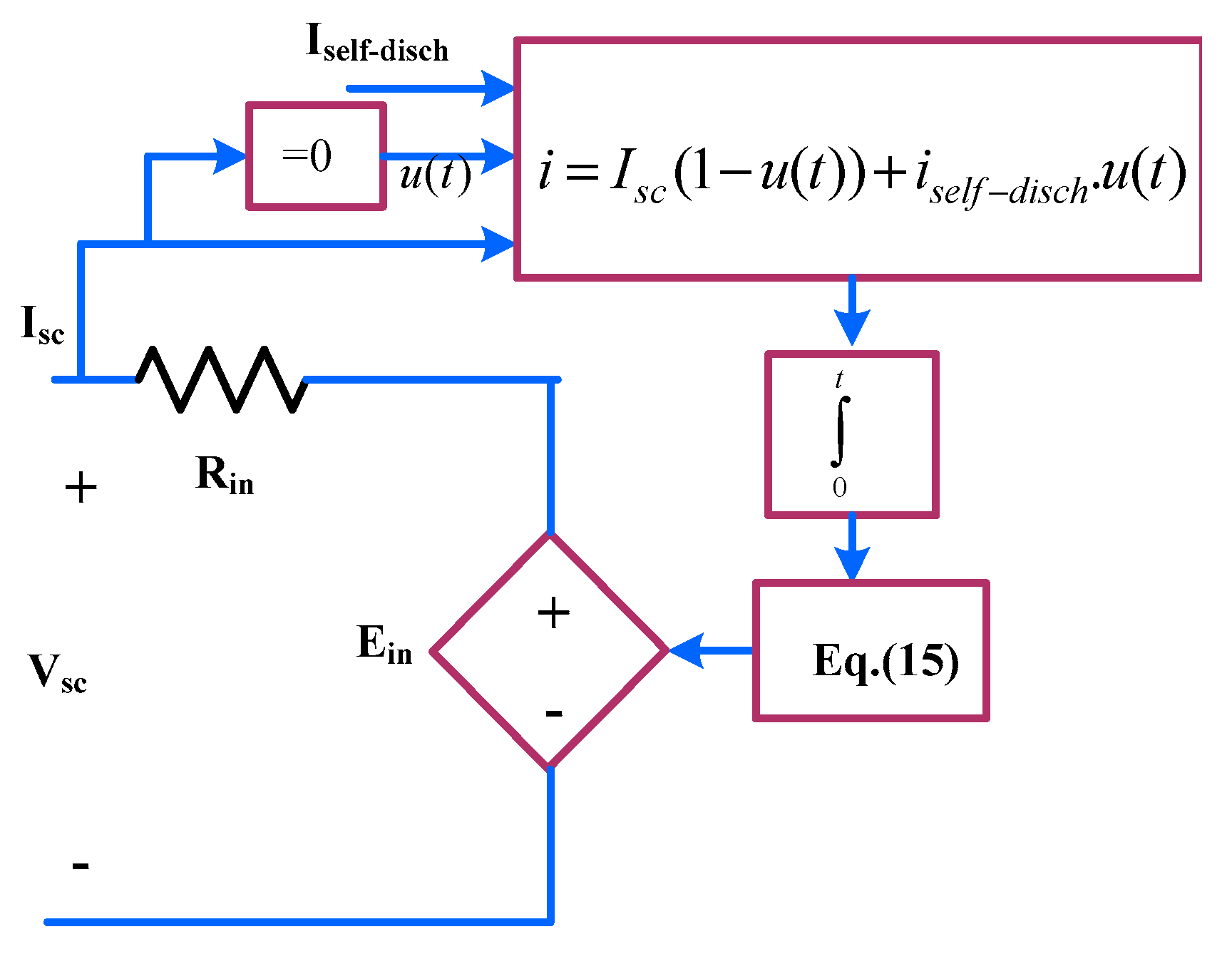
The supercapacitor was modeled by a controlled voltage source, as presented in Figure 8. The internal voltage of the supercapacitor is described as follows:
E S C ( i n t ) = v N s Q ( t ) d N p N e ε ε 0 A i + 2 N e N s R T F + sin h 1 ( Q ( t ) N p N e 2 A i 8 R T ε ε 0 c )
where Ns and Np are the number of series and parallel capacitors, Ne is the number of electrode layers, and ε and ε0 are permittivity of material and air, respectively. R and T are ideal gas constant and operating temperature, respectively, and 
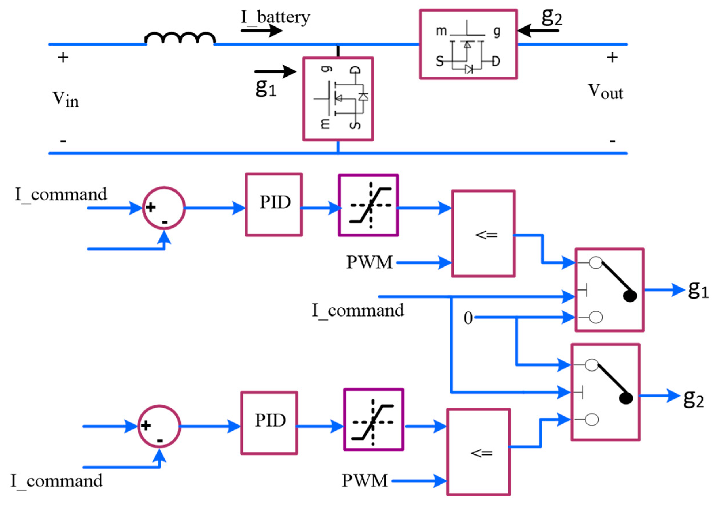
Ai is the interfacial area between electrodes and electrolyte. To connect SESS to the third rail, a bidirectional DC/DC converter was used. The schematic and the control circuit of this converter are presented in Figure 9 [16].
S1 only gets a turn on signal for charging, and S2 is turned on during discharging. More information about this type of bidirectional DC/DC converter can be found in the literature [28]. The ESS energy management unit was responsible for the command signal (I_command) and worked based on some general rules, as follows:
If the voltage of the line at the point of connection (VPCC) of the ESS was greater than the voltage set for triggering the charging process, it would charge until the state of charge ESS reached an upper limit. Similarly, if the VPCC was smaller than a specific limit set for discharging, the ESS would discharge until the state of charge reached a lower limit. For safe operation, the upper and lower limits were considered in this paper to be 90% and 40%, respectively. Other than these two conditions, the ESS remained idle.

4. Case Study

In this section, the performance of FESS and SESS for the application of peak demand reduction and voltage regulation is investigated and compared. The cost analysis is also presented for each technology in each application.

4.1. Peak Demand Reduction

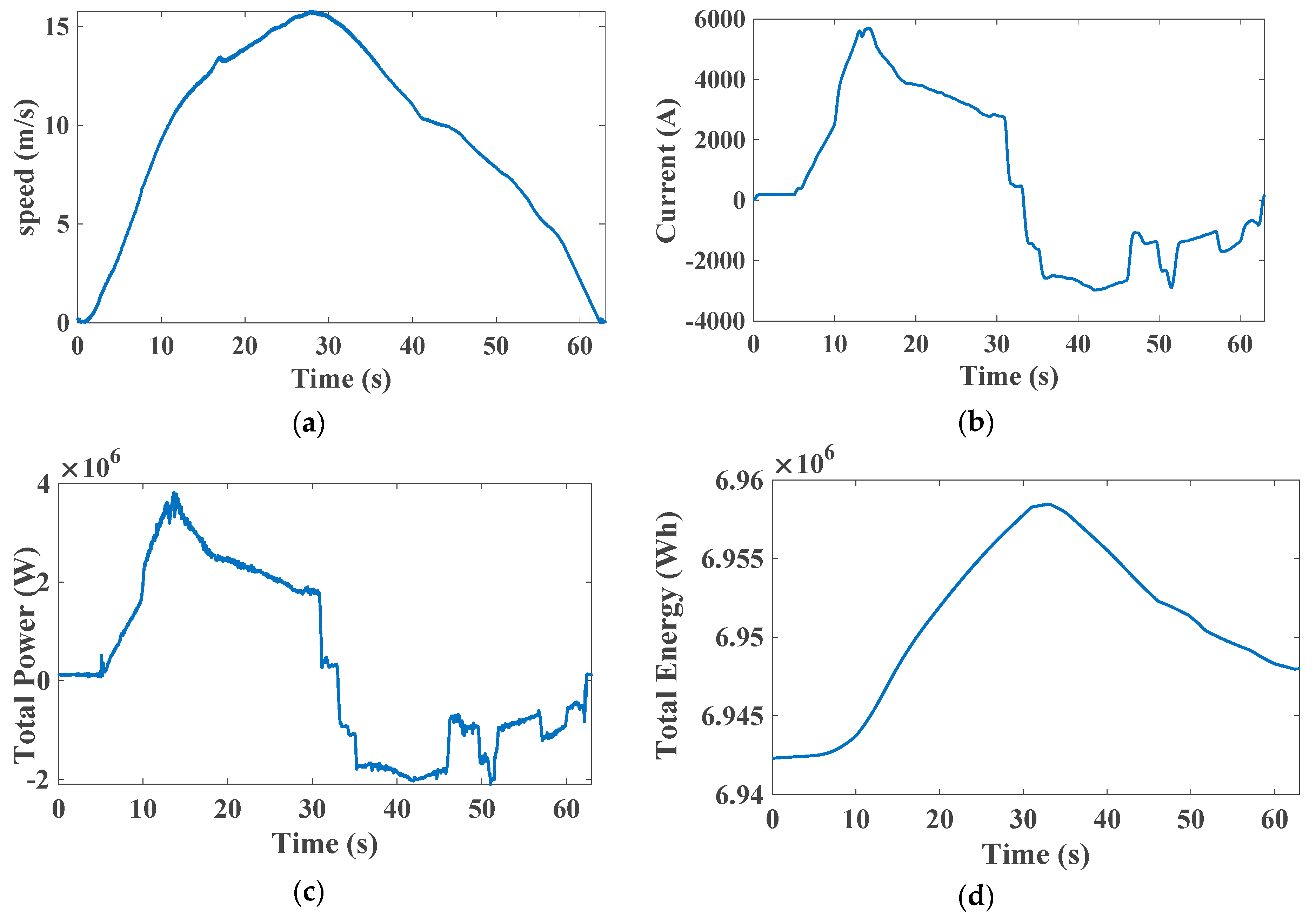
A typical train speed, current, power, and energy profile of a train are presented in 
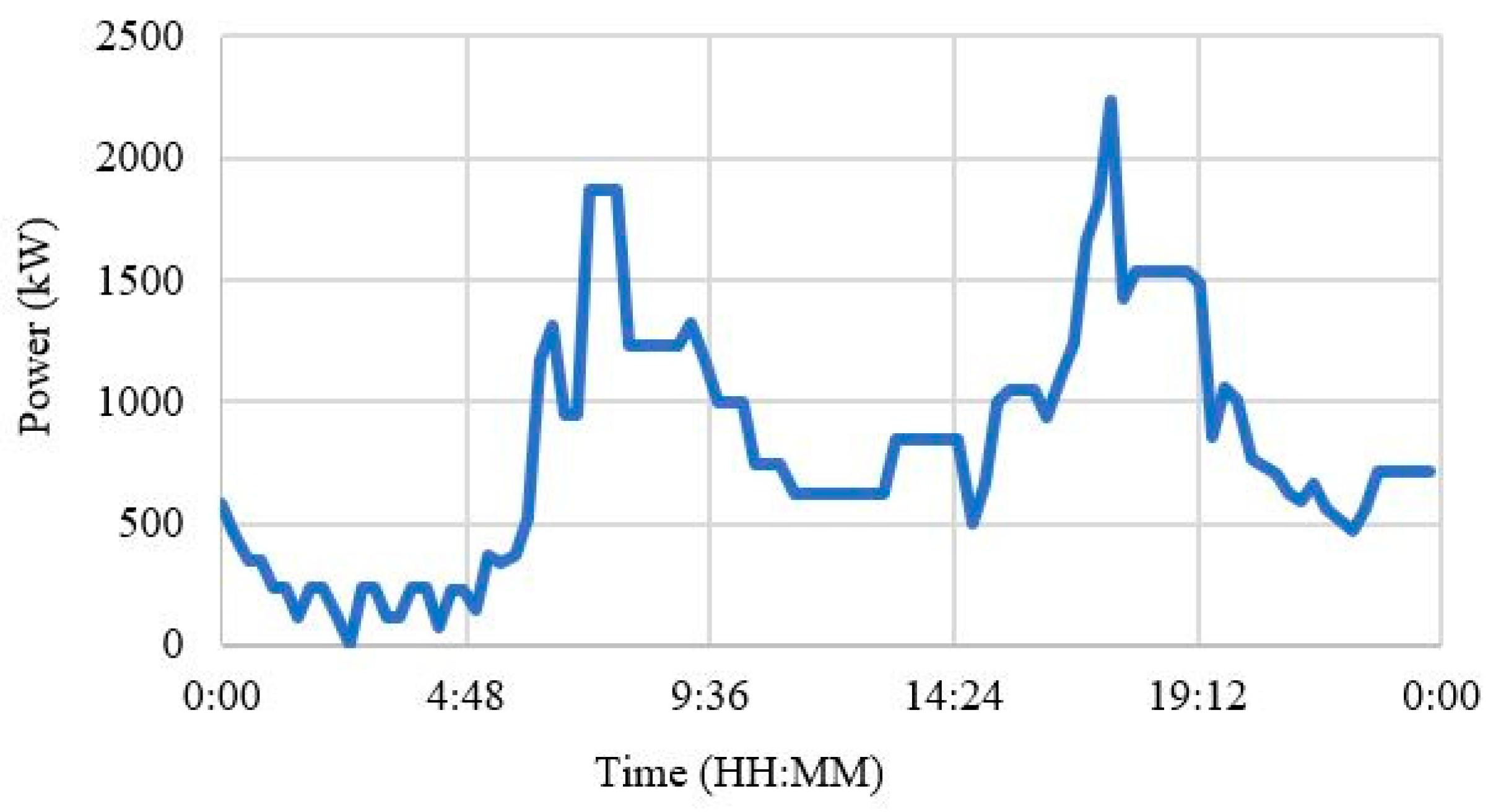
Figure 10. As illustrated, during acceleration (0–33 s), a train accelerates with a maximum rate to reach its maximum speed. During this interval, a significant amount of current/power is requested from a nearby substation. During the transit system rush hours, the number of trains increases, and trains run with shorter headway (2–3 min). Therefore, a considerable number of train acceleration events happen near each substation during each 15 min interval. Consequently, substations will have high peak demand. An example of a 24 h power profile of substation B in a typical weekday is presented in Figure 11. As can be observed, there is peak demand for 2238 kW at around 5:30 p.m.
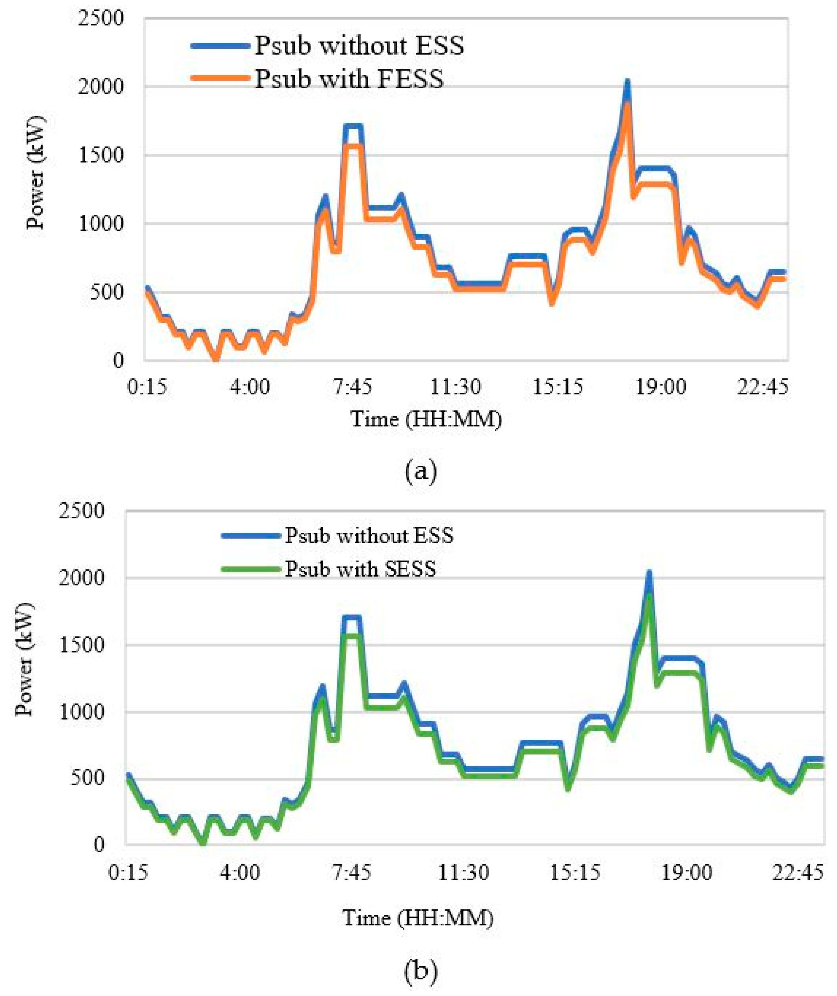
In this case study, FESS and SESS were controlled to discharge during train acceleration and charge by regenerative braking energy, to provide a 10% peak demand reduction in substation B. They were sized in a way that provided a 705 A current for 12.3 seconds (353 kW, 1.2 kWh). A Maxwell supercapacitor (K2 series) [29,30,31,32] and VYCON flywheel [8] were used as the ESS technologies. Based on the ESS technology characteristics (for example, maximum voltage and current of the cell or module), they need to be oversized to provide the required current and voltage. ESSs sizing information is presented in Table 4. The ESSs were separately placed in substation B and tested. The results are presented in Figure 12. As can be seen, both ESS technologies were capable of reducing the peak of substation B for the desired value of 10%.

4.2. Voltage Regulation

When a train accelerates, a significant amount of power/current is drawn from the third rail; therefore, the third rail voltage drops inversely, proportional to the current to provide the requested amount of current/power. For example, in a system which is working with a nominal voltage of 650 VDC, the third rail voltage can drop to 580–620 VDC during acceleration. In a weak system, the voltage may drop to an even lower value. Since train acceleration happens frequently, these frequent voltage drops may affect train performance, and may cause damage to other equipment connected to the third rail. By installing ESSs, when the voltage drops below a certain level, the ESS will discharge to the third rail and thus prohibit any further voltage drop. This behavior for both SESS and FESS (modeled here as a current source) is presented in Figure 13.
In this case study, ESS was sized to provide 13% voltage enhancement in the third rail next to substation B. ESS was sized to provide 4500 A with the duration of 17 s (2.93 MW, 66 MW.s) during train acceleration. A Maxwell supercapacitor (K2 series) and VYCON flywheel were used as the ESS technologies. For SESS, 9 strings of 180 cells in series were required, while for FESS 24, modules were required. As mentioned before, the voltage and current of ESS cells or modules were limited, and ESSs needs to be oversized to provide the required output.

4.3. Cost Analysis

To obtain an accurate selection of suitable technologies for each application, cost analysis of running ESS for 10 years was performed. The cost metrics that were considered included: initial cost (the cost normalized based on the power and energy of ESS), energy conversion cost, balance of plant cost (the owner’s cost for project engineering and project management, land, and grid connection equipment), operation and maintenance cost (O&M), and replacement cost [10,25].
The initial cost of the ESS was calculated based on Equation (16):
C = C $ / k W P + C $ / k W h E
where C$/kW and C$/kWh are the cost per kW and kWh, respectively. The costs for SESS range from 100–300 $/kW and 300–2000 $/kWh. However, for FESS, costs range from 250–350 $/kW and 1000–5000 $/kWh. In this study, we considered the average value for each cost and each technology [33]. The cost of energy conversion and balance of plant were 153 $/kW and 100 $/kW, respectively. Operation and maintenance costs were classified into fixed cost and variable cost. Fixed cost was considered 2% of the initial cost and included the cost of annual tax and insurance. The variable cost for the supercapacitor was 6.7 $/kW per year and included the cost of periodical inspection of the cells and interconnection cable and fixing, if there was a problem confirming the DC voltage and current. The variable cost of FESS was 9.1 $/kW per year and included the service cost for changing the air tank filter, oil, and bearing [10]. The replacement cost was associated with the life of the energy storage system. For the supercapacitor, the end of life is the moment when capacity goes down to 80% of its initial capacity, or when its ESR doubles. A supercapacitor is claimed by manufacturers to have a 10 year life span, while a recent study showed that after almost 5 years the cells need to be replaced [34]. To the best of the authors’ knowledge, there is no credible information available for the flywheel from real-world implementation; it is claimed by the manufacturer to have a 15–20 year life span. In this study, we considered the life span of the supercapacitor and flywheel, respectively, as 5 and 15 years. The results of the cost analysis for the application of peak demand reduction are presented in Table 5.
Based on the aforementioned assumptions, it was concluded that the flywheel has a lower cost than the supercapacitor, and can be considered a more cost-effective solution for peak demand reduction.
The results of the cost analysis for application of voltage regulation are presented in Table 6. It was concluded that the flywheel has a lower cost than the supercapacitor and can be considered as a more cost-effective solution for voltage regulation.

5. Conclusions

In this study, the application of flywheel and supercapacitor energy storage systems in electric rail transit systems for peak demand reduction and voltage regulation services was investigated. Each technology was described in detail. Examples of application in an electric rail transit system were presented, and the general characteristics of the two technologies were compared. Two case studies were considered for testing performance in the electric rail transit system. The results of the case studies show that both technologies have functional requirements for both applications. However, bearing in mind the cost factor, flywheel energy storage can be considered a suitable option for peak demand reduction and voltage regulation.

Author Contributions

Methodology, M.K. and A.M.; investigation, M.K. and A.M.; data curation, M.K. and A.M.; manuscript preparation, M.K. and A.M.

Funding

This research received no external funding.

Conflicts of Interest

Authors declare no conflict of interest.

References

  1. González-gil, A.; Palacin, R.; Batty, P.; Powell, J.P. Energy-efficient urban rail systems: Strategies for an optimal management of regenerative braking energy. Transp. Res. Arena 2014, 44, 374–388. [Google Scholar]
  2. Schroeder, M.P.; Yu, J.; Teumim, D. Guiding the Selection and Application of Wayside Energy Storage Technologies for Rail Transit and Electric Utilities; Transportation Cooperative Research Program (TCRP), The National Academic Press: Washington, DC, USA, 2010. [Google Scholar]
  3. Khodaparastan, M.; Mohamed, A.A.; Brandauer, W. Recuperation of Regenerative Braking Energy in Electric Rail Transit Systems. IEEE Trans. Intell. Transp. 2018, 20, 1–17. [Google Scholar] [CrossRef]
  4. Amiryar, M.; Pullen, K. A Review of Flywheel Energy Storage System Technologies and Their Applications. Appl. Sci. Artic. 2017, 7, 286. [Google Scholar] [CrossRef]
  5. Arani, A.K.; Karami, H.; Gharehpetian, G.B.; Hejazi, M.S.A. Review of flywheel energy storage systems structures and applications in power systems and microgrids. Renew. Sustain. Energy Rev. 2017, 69, 9–18. [Google Scholar] [CrossRef]
  6. Mousavi, S.M.G.; Faraji, F.; Majazi, A.; Al-haddad, K. A comprehensive review of Flywheel Energy Storage System technology. Renew. Sustain. Energy Rev. 2017, 67, 477–490. [Google Scholar] [CrossRef]
  7. Beacon Power. Carbon Fiber Flywheels. 2018. Available online: https://beaconpower.com/carbon-fiber-flywheels/ (accessed on 18 September 2019).
  8. VYCON. Vycon-The Proven Flywheel Energy Storage System for Rail. 2017. Available online: https://vyconenergy.com/2017/03/13/vycon-showcases-flywheel-energy-storage-system-for-metro-rail-power-regeneration-at-asia-pacific-rail-expo/ (accessed on 18 September 2019).
  9. Östergard, R. Flywheel Energy Storage a Conceptual Study Flywheel Energy Storage—A Conceptual Study; Uppsala Universitet: Uppsala, Sweden, 2011. [Google Scholar]
  10. EPRI. Handbook of Energy Storage for Transmission & Distribution Applications. 2003. Available online: https://www.sandia.gov/ess-ssl/publications/ESHB%201001834%20reduced%20size.pdf. (accessed on 18 September 2019).
  11. Liu, H.; Jiang, J. Flywheel energy storage—An upswing technology for energy sustainability. Energy Build. 2007, 39, 599–604. [Google Scholar] [CrossRef]
  12. Jackson, D. High-speed flywheels cut energy bill. Railw. Gaz. Int. 2001, 1, 7–9. [Google Scholar]
  13. Maxwell. Maxwell Ultracapacitor Saftey Data Sheet. 2015. Available online: https://www.maxwell.com/images/documents/Safety_Datasheet_3000389_EN_4.pdf. (accessed on 18 September 2019).
  14. Khodaparastan, M.; Mohamed, A. Modeling and Simulation of Regenerative Braking Energy in DC Electric Rail Systems. In Proceedings of the 2018 IEEE Transportation Electrification Conference and Expo (ITEC), Long Beach, CA, USA, 13–15 June 2018; pp. 1–6. [Google Scholar]
  15. Khodaparastan, M.; Dutta, O.; Saleh, M.; Mohamed, A. Modeling of DC Electric Rail Transit Systems with Wayside Energy Storage. IEEE Trans. Veh. Technol. 2018, 68, 1–9. [Google Scholar] [CrossRef]
  16. Khodaparastan, M.; Mohamed, A. A study on supercapacitor wayside connection for energy recuperation in electric rail systems. In Proceedings of the IEEE Power & Energy Society General Meeting, Chicago, IL, USA, 16–20 July 2017; pp. 1–5. [Google Scholar]
  17. Burke, A. Ultracapacitors: Why, how, and where is the technology. J. Power Sources 2000, 91, 37–50. [Google Scholar] [CrossRef]
  18. Halper, M.S.; Ellenbogen, J.C. Supercapacitors: A Brief Overview; MITRE Nanosyst. Gr.: McLean, VA, USA, 2006. [Google Scholar]
  19. Kötz, R.; Carlen, M.J.E.A. Principles and applications of electrochemical capacitors. Electrochim. Acta 2000, 45, 2483–2498. [Google Scholar] [CrossRef]
  20. Khodaparastan, M.; Mohamed, A. Supercapacitors for electric rail transit systems. In Proceedings of the 2017 6th International Conference on Renewable Energy Research and Applications, ICRERA, San Diego, CA, USA, 5–8 November 2017; pp. 896–901. [Google Scholar]
  21. Nasri, A.; Moghadam, M.F.; Mokhtari, H. Timetable optimization for maximum usage of regenerative energy of braking in electrical railway systems. In Proceedings of the SPEEDAM 2010, Pisa, Italy, 14–16 June 2010; pp. 1218–1221. [Google Scholar]
  22. Barrero, R.; Tackoen, X.; van Mierlo, J. Stationary or onboard energy storage systems for energy. Proc. Inst. Mech. Eng. Part F J. Rail Rapid Transit 2010, 224, 207–225. [Google Scholar] [CrossRef]
  23. Siemens, A.G. Increasing Energy Efficiency Optimized Traction Power Supply in Mass Transit Systems; Siemens 2011. Available online: https://kipdf.com/rail-electrification_5ac3f2361723dd3a8f78ae1c.html (accessed on 18 September 2019).
  24. Ciccarelli, F.; Di Noia, L.P.; Rizzo, R. Integration of Photovoltaic Plants and Supercapacitors in Tramway Power Systems. Energies 2018, 11, 410. [Google Scholar] [CrossRef]
  25. Chen, H.; Cong, T.N.; Yang, W.; Tan, C.; Li, Y.; Ding, Y. Progress in electrical energy storage system: A critical review. Prog. Nat. Sci. 2009, 19, 291–312. [Google Scholar] [CrossRef]
  26. Vazquez, S.; Lukic, S.M.; Galvan, E.; Franquelo, L.G.; Carrasco, J.M. Energy Storage Systems for Transport and Grid Applications. IEEE Trans. Ind. Electron. 2010, 57, 3881–3895. [Google Scholar] [CrossRef] [Green Version]
  27. Farhadi, M.; Mohammed, O. Energy Storage Technologies for High-Power Applications. IEEE Trans. Ind. Appl. 2016, 52, 1953–1962. [Google Scholar] [CrossRef]
  28. Erickson, R.W.; Maksimovic, D. Fundamentals of Power Electronics; Springer Science & Business Media: Berlin/Heidelberg, Germany, 2007. [Google Scholar]
  29. Maxwell. K2 Ultracapacitors—2. 7V Series Features and Benefits—Typical Characteristics; Maxwell, 2014. Available online: https://www.maxwell.com/images/documents/K2_2_85V_DS_3000619EN_3_.pdf (accessed on 18 September 2019).
  30. Khodaparastan, M.; Dutta, O.; Mohamed, A. Wayside Energy Storage System for Peak Demand Reduction in Electric Rail Systems. In Proceedings of the IEEE industrial application society annual meeting (IAS2018), Portland, OR, USA, 23–27 September 2018; pp. 1–5. [Google Scholar]
  31. Atlantique, E. London Underground Energy Recovery Trial Proves Successful; Railway Gazett, 2016. Available online: https://www.railwaygazette.com/london-underground-energy-recovery-trial-proves-successful/41430.article (accessed on 18 September 2019).
  32. Konishi, T.; Morimoto, H.; Aihara, T.; Tsutakawa, M. Fixed energy storage technology applied for DC electrified railway. IEEJ Trans. Electr. Electron. Eng. 2010, 5, 270–277. [Google Scholar] [CrossRef]
  33. Ibrahim, H.; Ilinca, A.; Perron, J. Energy storage systems—Characteristics and comparisons. Renew. Sustain. Energy Rev. 2008, 12, 1221–1250. [Google Scholar] [CrossRef]
  34. Kovaltchouk, T.; Multon, B.; Ahmed, H.B.; Aubry, J.; Venet, P. Enhanced Aging Model for Supercapacitors Taking into Account Power Cycling: Application to the Sizing of an Energy Storage System in a Direct Wave Energy Converter. IEEE Trans. Ind. Appl. 2015, 51, 2405–2414. [Google Scholar] [CrossRef]
Figure 1. Flywheel structure.
Inventions 04 00062 g001
Figure 2. Electrochemical double layer capacitors (EDLC) structure.
Inventions 04 00062 g002
Figure 3. Energy storage systems (ESSs) characteristics.
Inventions 04 00062 g003
Figure 4. System Overview.
Inventions 04 00062 g004
Figure 5. Electric drive schematic.
Inventions 04 00062 g005
Figure 6. Electric drive control.
Inventions 04 00062 g006
Figure 7. Flywheel model.
Inventions 04 00062 g007
Figure 8. Supercapacitor model.
Inventions 04 00062 g008
Figure 9. Bidirectional DC/DC converter model.
Inventions 04 00062 g009
Figure 10. Train performance profile; (a) speed, (b) current, (c) power, and (d) energy.
Inventions 04 00062 g010
Figure 11. Substation B power profile.
Inventions 04 00062 g011
Figure 12. Substation peak demand reduction; (a) with flywheel ESS, (b) with supercapacitor ESS.
Inventions 04 00062 g012
Figure 13. Voltage regulation.
Inventions 04 00062 g013
Table 1. Application of flywheel energy storage in rail transit systems.
LocationCompanySizePurposeResults/CommentReference
Los Angeles MetroVYCON2 MW, 8.33 kWhEnergy savingThe total weekly saving reported as 10.5 MWh (11.5%)[13]
Hanover (Germany)Pillar0.2 MW, 1.5 kWhEnergy savingTested in 2004 and showed energy saving of 462 kwh/year[7,14]
London UndergroundUrenco Power Technology3 units of 100 kWEnergy savingThis was a testing trial done in 2000[15]
Keihin Electric Railway (Japan)-3 MW, 25 kWhVoltage regulation12% energy saving was reported[16]
Far Rockaway (NY)Urenco Power Technology1 MWPeak demandEnergy saving of 7–25% was reported[7,14]
Table 2. Application of supercapacitor energy storage (SESS) in rail transit systems.
LocationVoltagePurposeCommentRef
Seibu1500 VEnergy Saving-[15]
Columbia1650 VEnergy SavingMaxwell 125 V modules were used[15]
Tehran-Energy Saving25% energy saving achieved[21]
Brussels850 VEnergy Saving37% energy saving achieved[22]
Toronto600 VEnergy SavingSitra SESS by simense was used[23]
Madrid750 VVoltage ImprovementSitra SESS by simense was used[23]
Beijing750 VEnergy SavingSitra SESS by simense was used[23]
Naples750 VEnergy SavingIntegration of PV farm and SESS[24]
Table 3. Power and energy characteristics of flywheen ESS and supercapacitor ESS.
CaseskW/kgMW/m3Wh/kgkWh/m3
Supercapacitor0.5–50.4–102.5–15150–500
Flywheel1–51–2.510–5020–80
Table 4. FESS and SESS sizing information.
Supercapacitor CellC = 3000 F, Vmax = 3, ESRDC = 0.27 mΩFlywheel Module125 kW, 750 Vdc
Configuration2 string*180 cells in seriesConfiguration3 modules in parallel
Max Voltage500Energy Storage1875 kW/sec
Stored Energy3.04 WhSpeed10,000 to 20,000 rpm
Specific Power5.9 kW/kgDC Current167 Adc
Imax Discharge500 A in 20 secondsRecharge Time15 seconds
Table 5. Cost analysis for peak demand reduction.
Cost OptionsSupercapacitor ($)Flywheel ($)
Initial433,258.10117,180.00
Energy Conversion System330,480.0057,375.00
Balance of Plant216,000.0037,500.00
Annual Operation and Maintenance Cost (O & M)23,137.165756.10
Replacement (every 5 years)763,738.10-
Replacement (in 10 years)1,527,476.20-
O & M (in 10 years)231,371.6057,560.00
Total cost (in 10 years)2,738,585.90384,365.00
Table 6. Cost analysis for voltage regulation.
Cost OptionsSupercapacitor ($)Flywheel ($)
Initial1,949,658.00937,440.00
Energy Conversion System1,487,160.00459,000.00
Balance of Plant972,000.00300,000.00
Annual O & M133,860.3655,228.80
Replacement (every 5 years)3,436,818.00-
Replacement (in 10 years)6,873,636.00-
Maintenance (in 10 years)1,338,603.60552,288.00
Total cost (in 10 years)12,621,057.602,248,728.00

