
Advanced Biomimetic Multispectral Curved Compound Eye Camera for Aerial Multispectral Imaging in a Large Field of View
Abstract
:1. Introduction
2. Multispectral Imaging System
2.1. System Design Theory
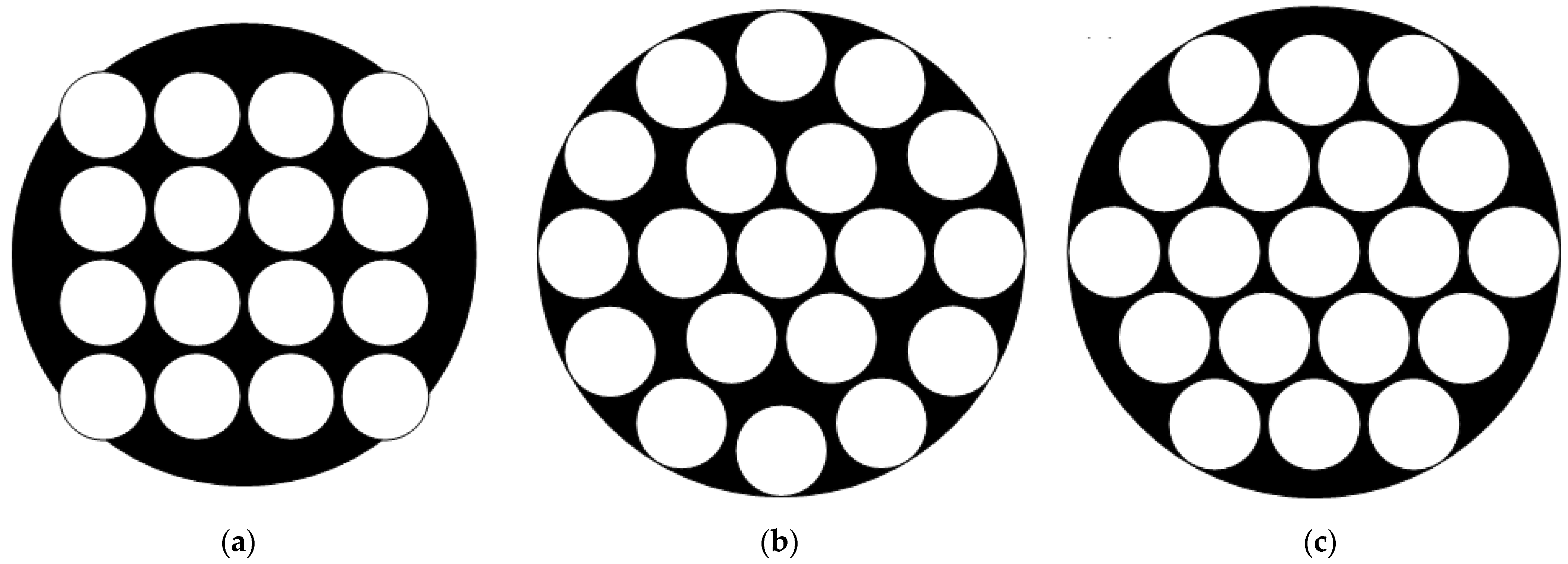
2.1.1. The Arrangement of the Multispectral Lens Array
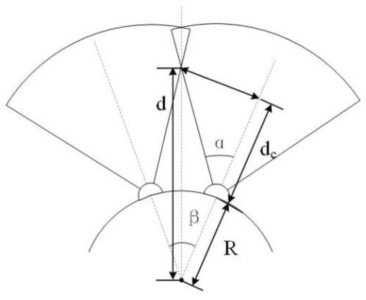
2.1.2. The FOV
2.1.3. The Focal Length
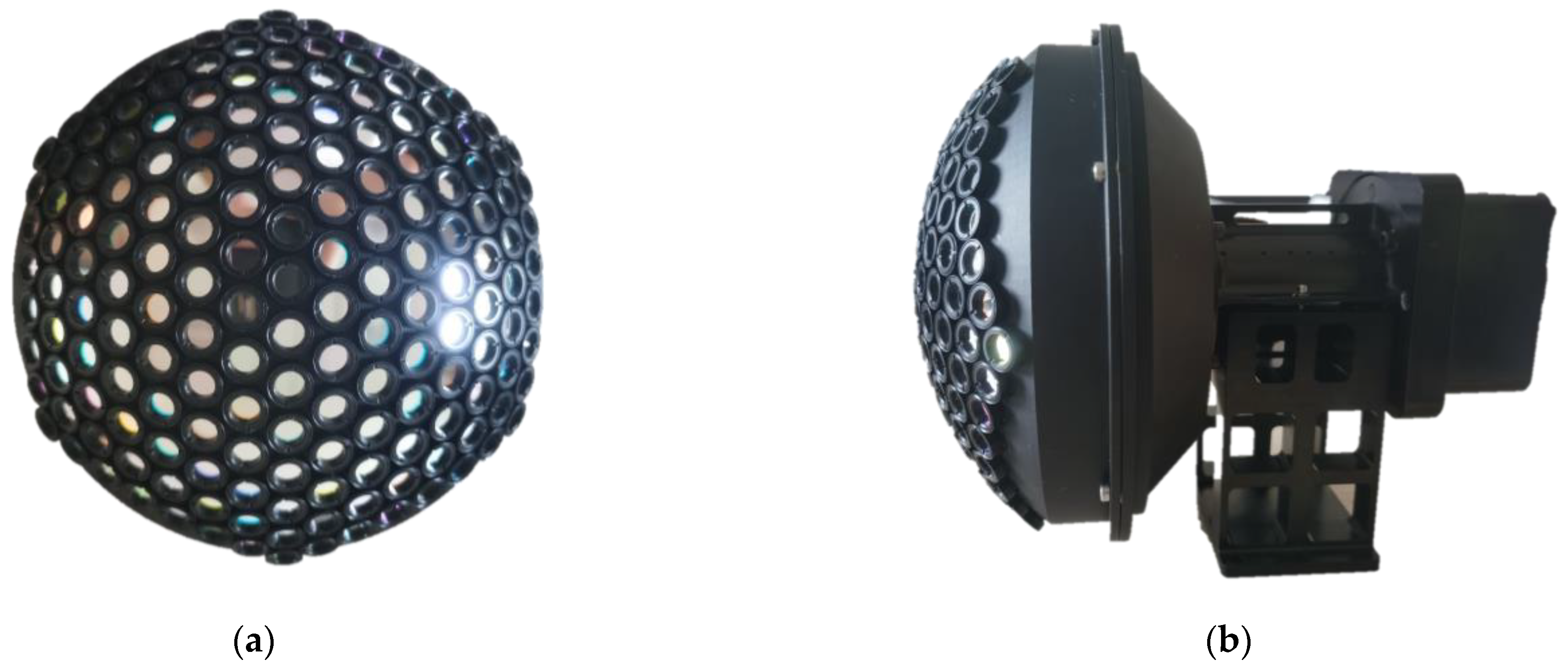
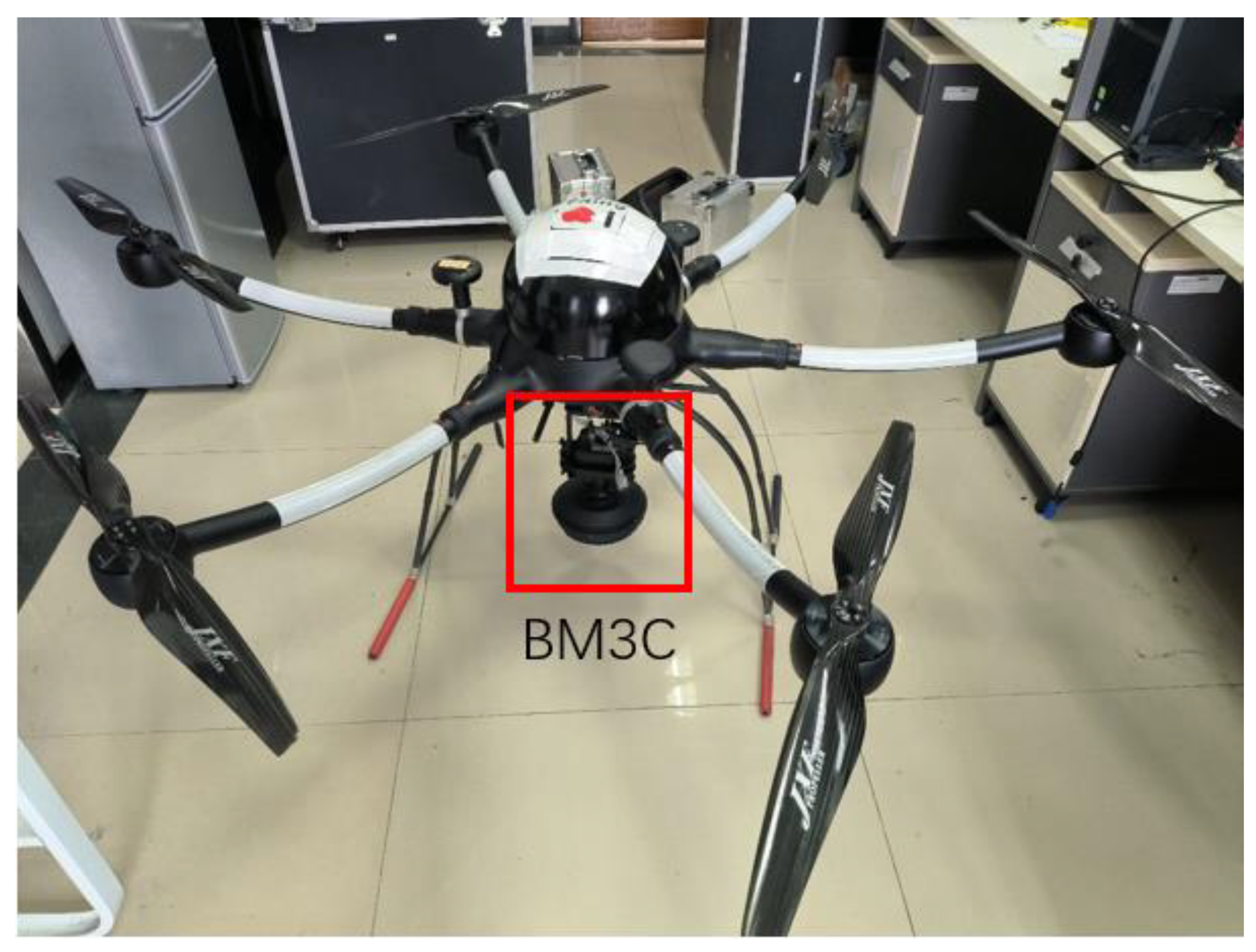
2.2. Prototype of BM3C
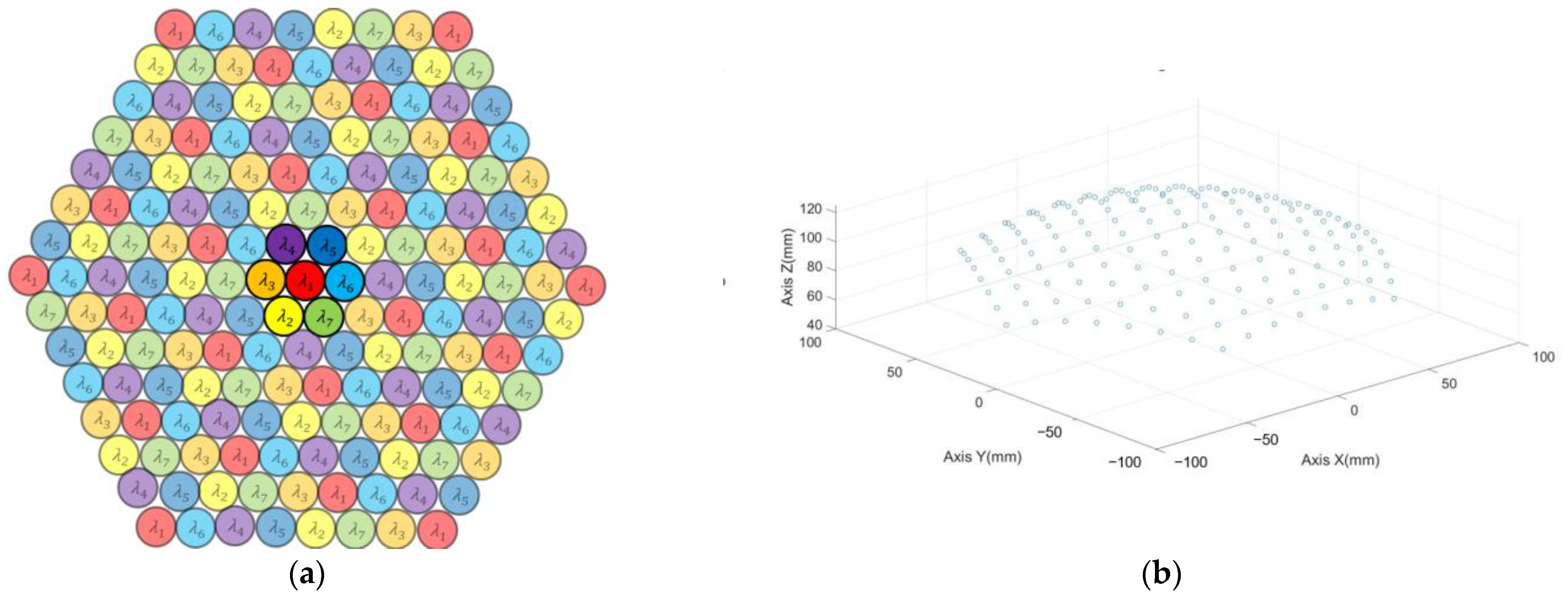
- A curved shell that contains 169 multispectral ommatidia; each ommatidium is a doublet lens with a focal length of 17.02 mm. Seven groups of narrowband filters are mounted before the ommatidia. The whole shell contains 25 filters with a nominal central wavelength of 500 nm and 6 groups of 24 filters with nominal central wavelengths at 560, 600, 650, 700, 750 and 800 nm; the arrangement of the filters is shown in Figure 2.
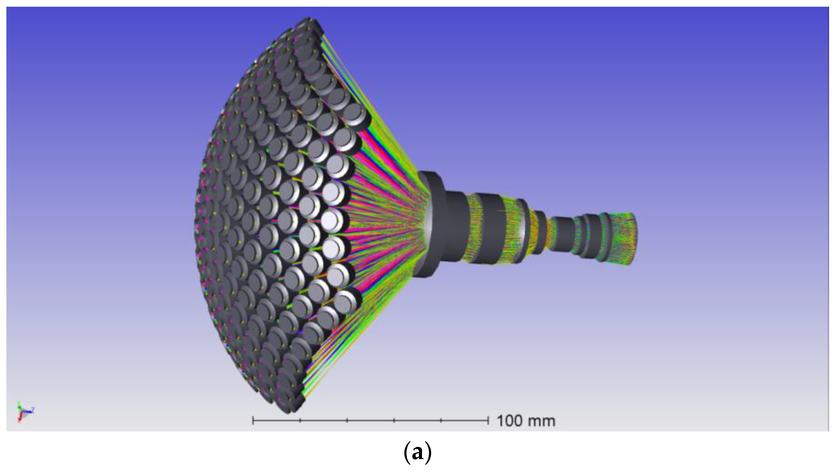
- An optical relay system with eight glass lenses, which transforms the curved image plane of the ommatidia array into a planar one. According to the Newton formula, the focal length is designed as 1 mm to achieve a whole system focal length of 2.7 mm.
- An Imperx Cheetah C5180M CMOS camera as the image sensor, with a resolution of 5120 × 5120 and a pixel size of 4.5 μm.
3. Image Reconstruction Method
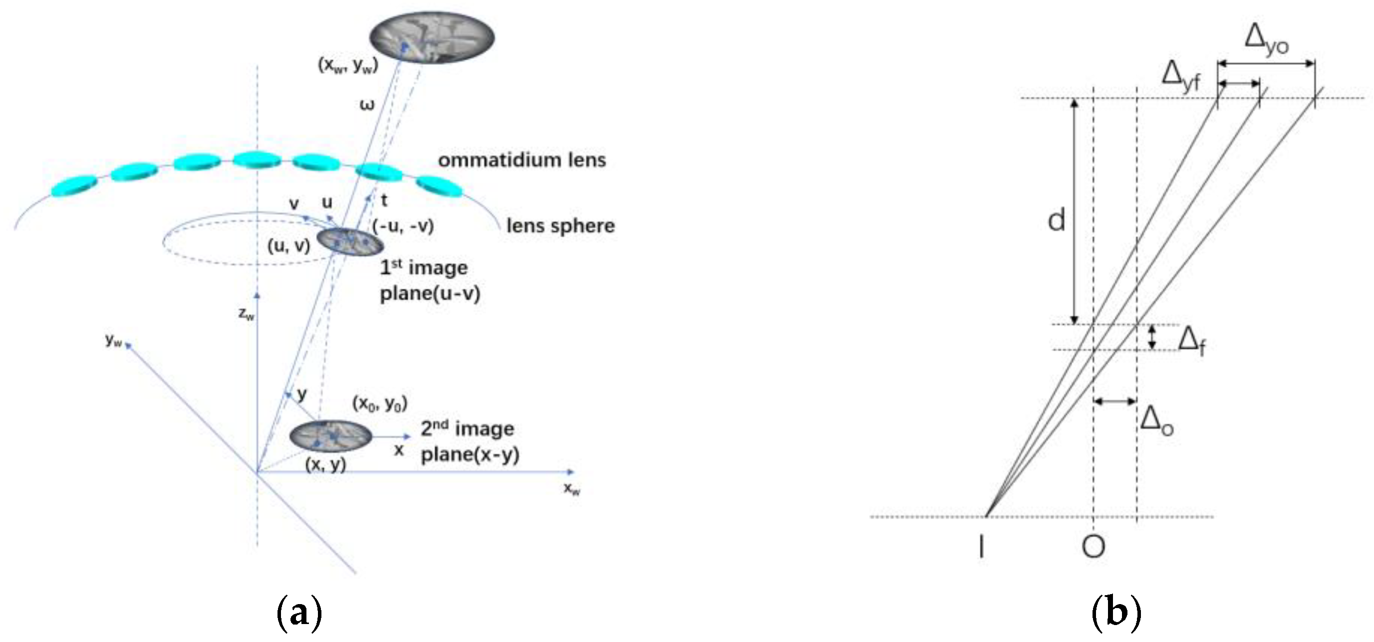
3.1. Method Based on Reprojection and Feature Detection
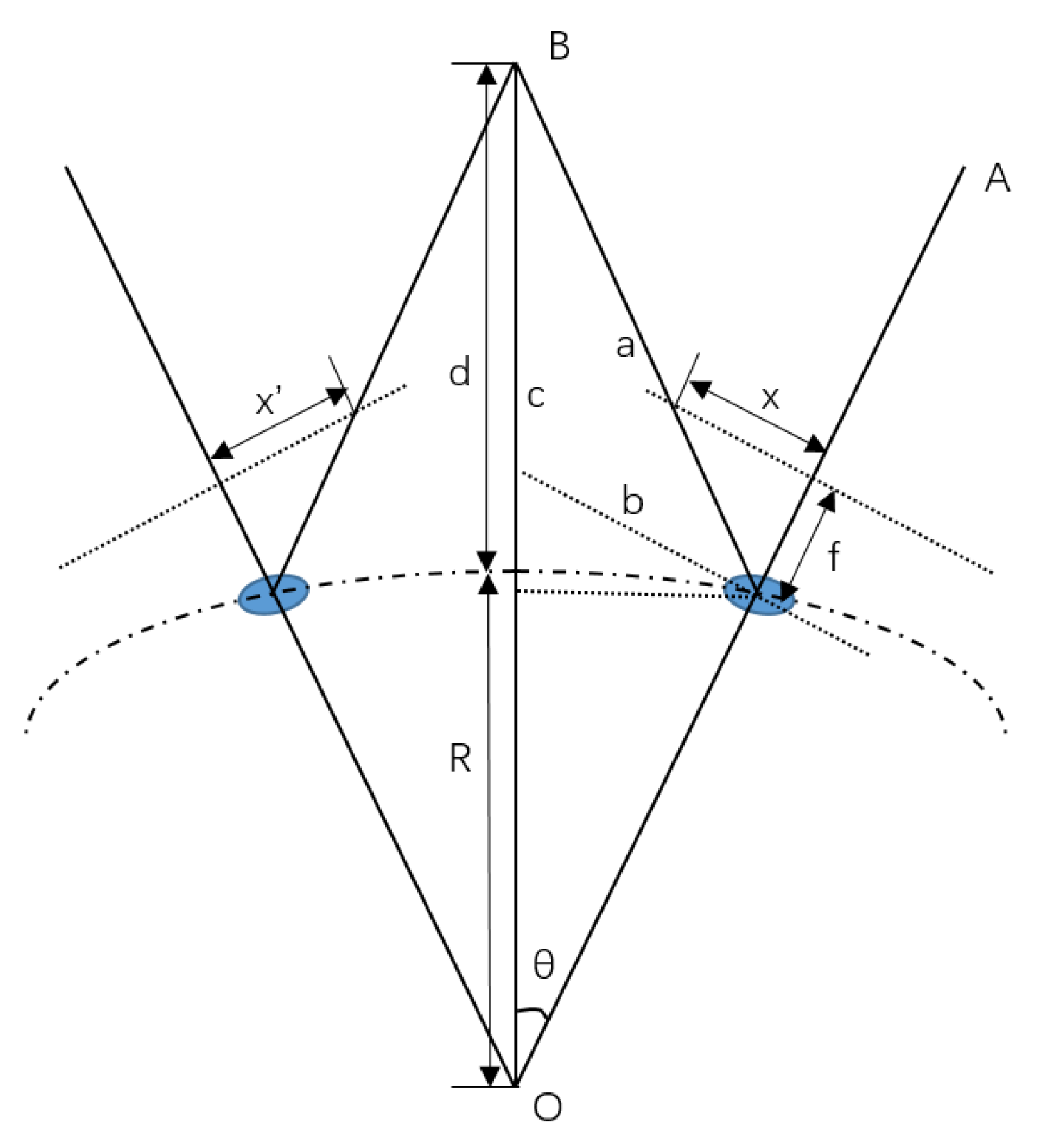
3.1.1. Error Analysis of the Image Reprojection
3.1.2. The Combined Reconstruction Method
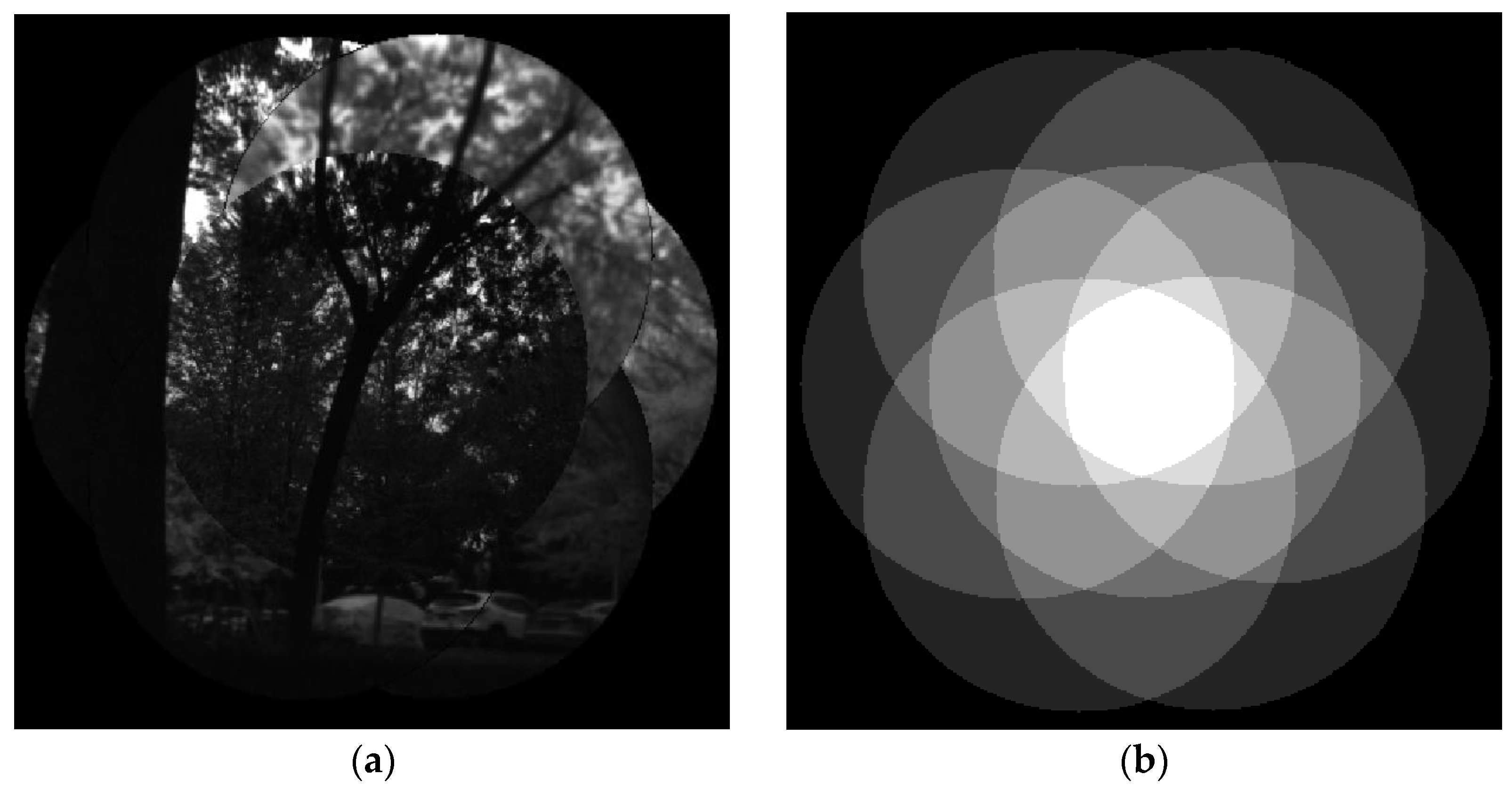
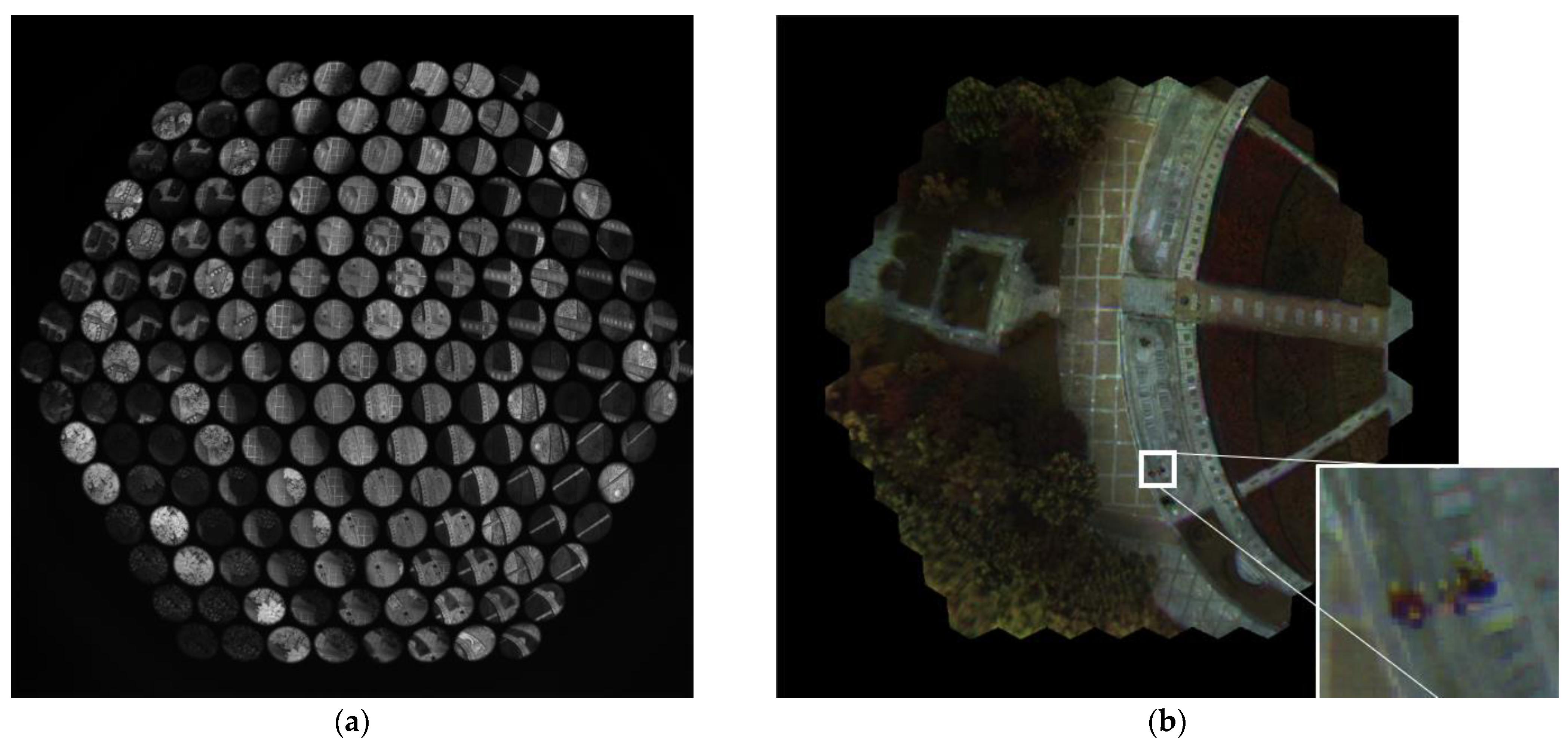
- First, the positions of all sub-images of ommatidia are found on the image plane with a generated and adjusted hexagon grid. As the center and radius of each circle image are determined, 127 multispectral clusters are noted by looking at the list of ommatidia and searching for the six nearest neighbor ommatidia for each ommatidium, except for the ones on the edge.
- After the multispectral clusters are noted, the image registration is performed based on the SIFT (Scale-Invariant Feature Transform) feature extraction algorithm, and the homography matrixes of the six surrounding channels in relation to the main channel are acquired with feature matching and the mismatching is reduced with the RANSAC (RANdom SAmple Consensus) algorithm [28]. The thresholds of the algorithm are manually adjusted to achieve the best matching and registration results.
- With the homography matrix and the image registration method, the projected positions of each pixel in the valid imaging area in the central ommatidium of each cluster are calculated and noted in a look-up table to achieve real-time multispectral image reconstruction.
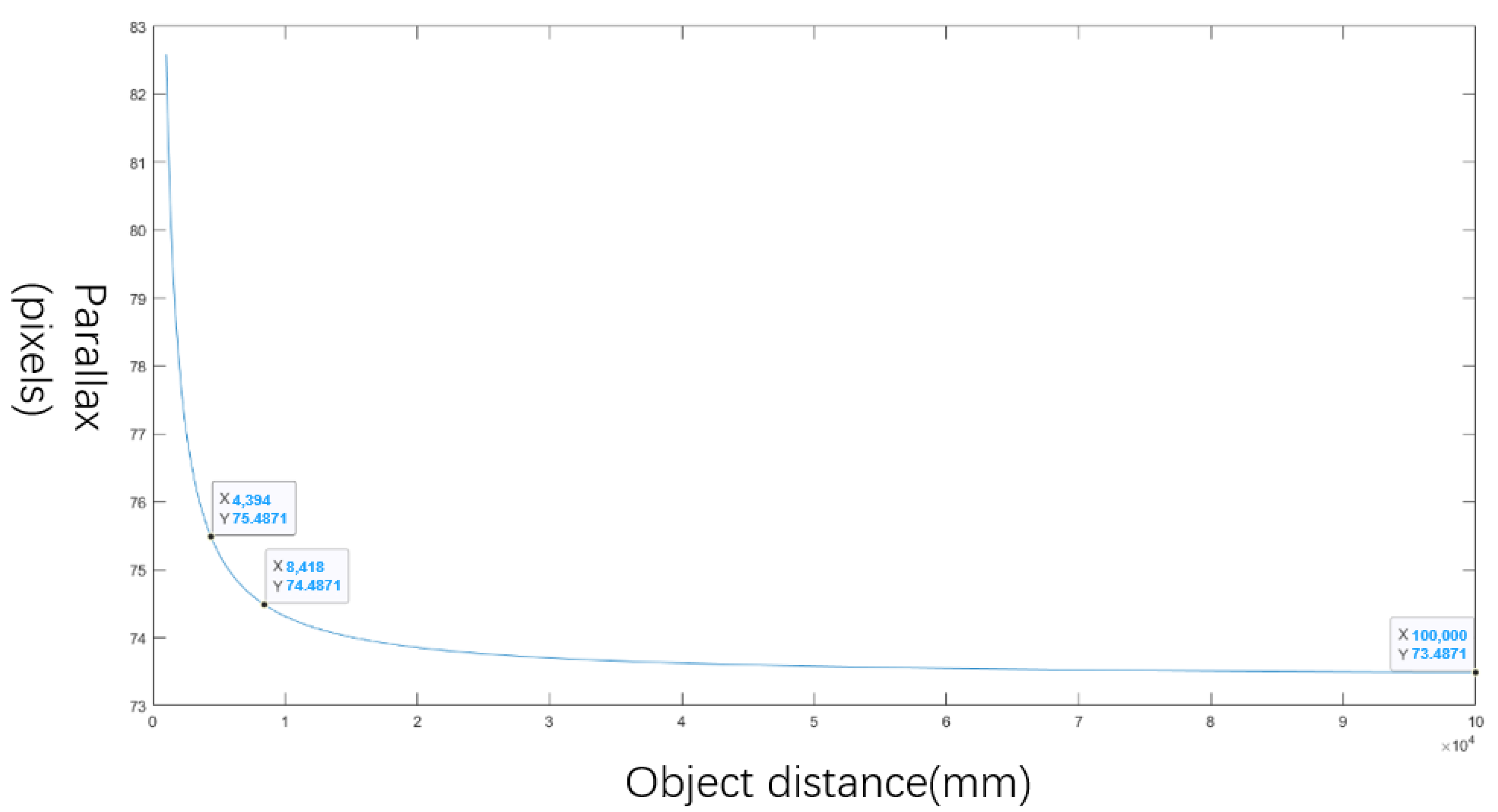
3.1.3. Working Distance
3.2. Method of Multispectral Information Acquisition
3.2.1. Radiometric Correction Based on Calibration
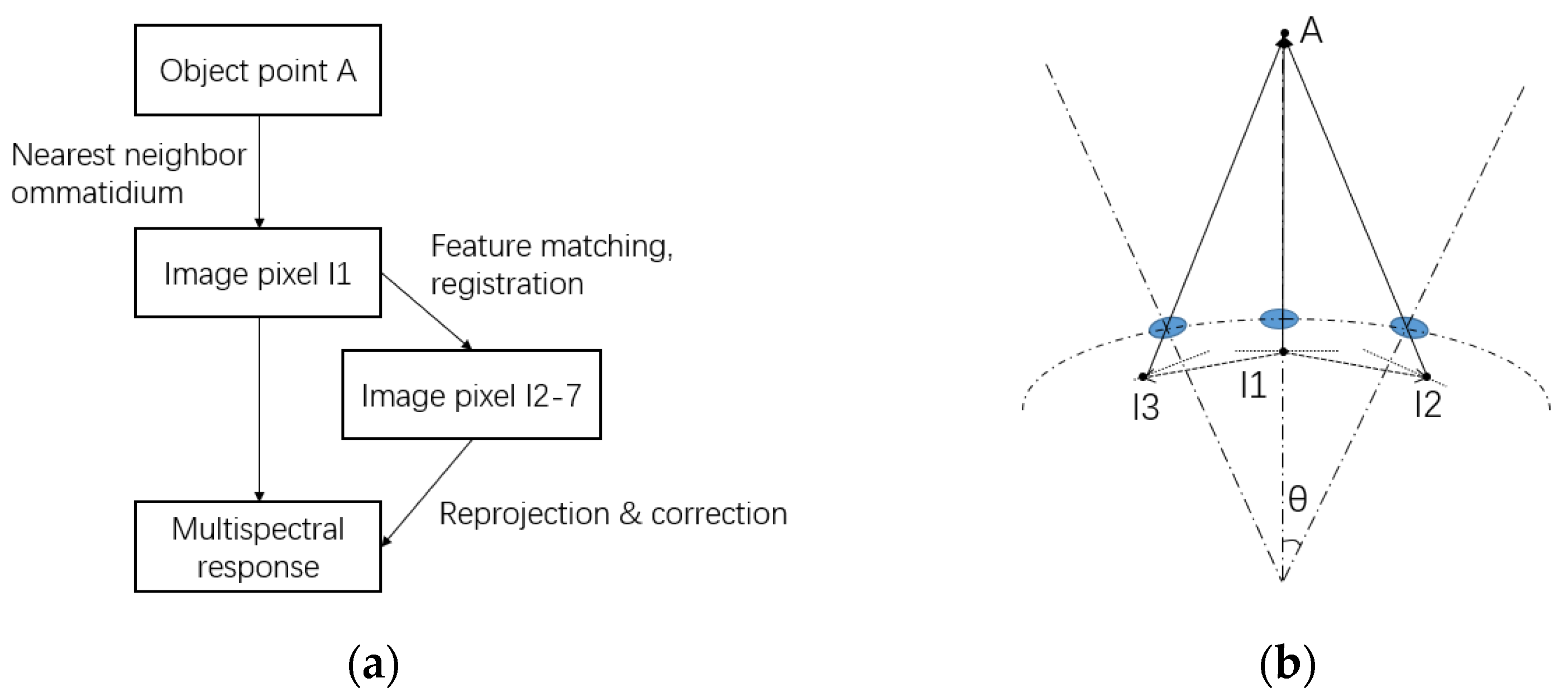
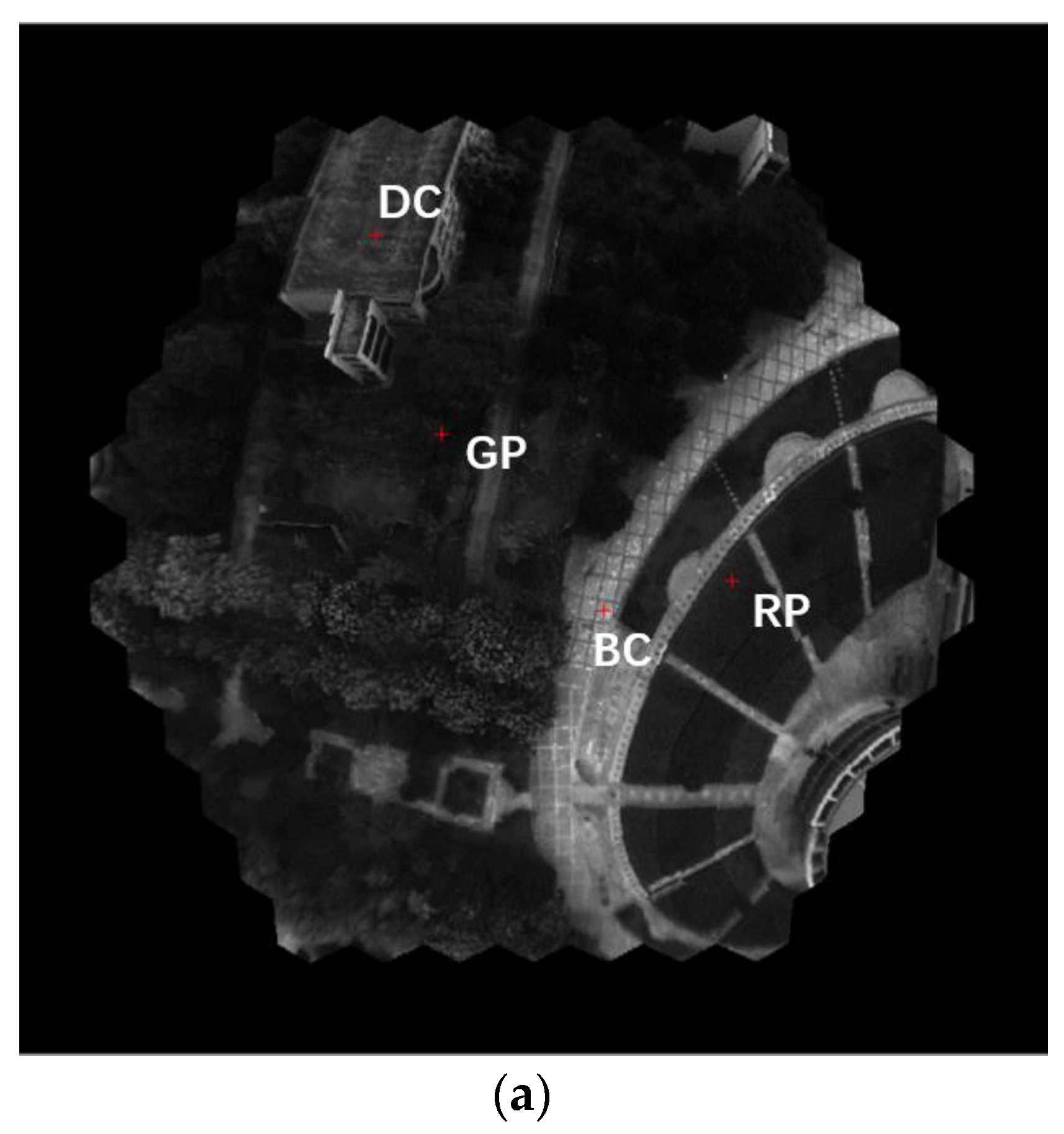
3.2.2. Multispectral Information Acquisition
- By solving the included angle of the chosen object pixel and the light axis of each ommatidium channel, the nearest channel is picked out, and the image pixel of the object is solved according to the projection theory.
- By checking the look-up table via the combined reconstruction method, the corresponding pixels in the other six images of the multispectral cluster are found.
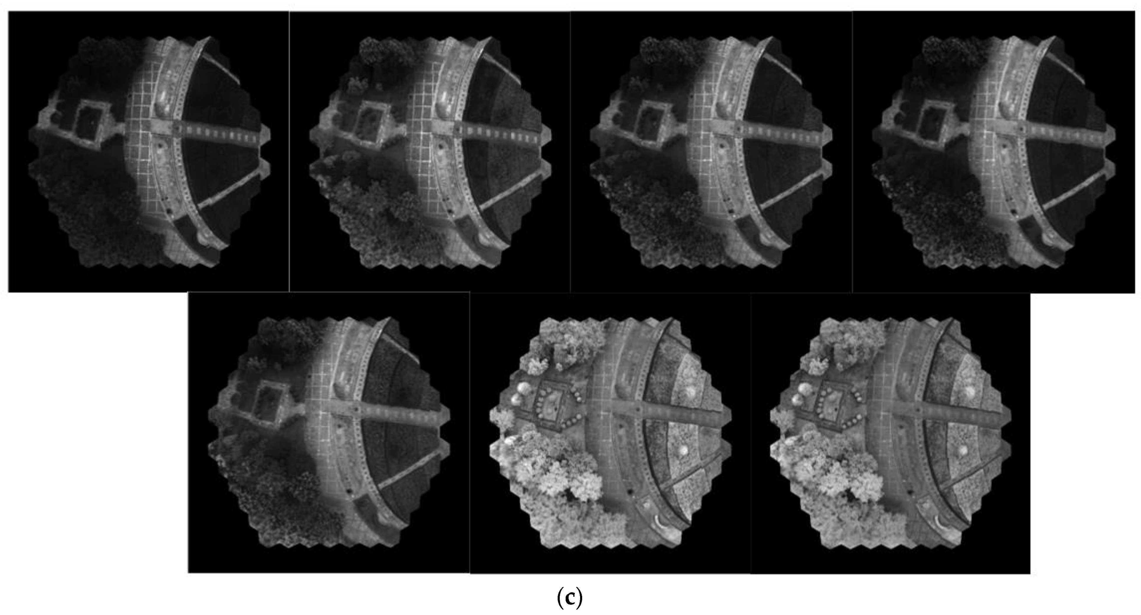
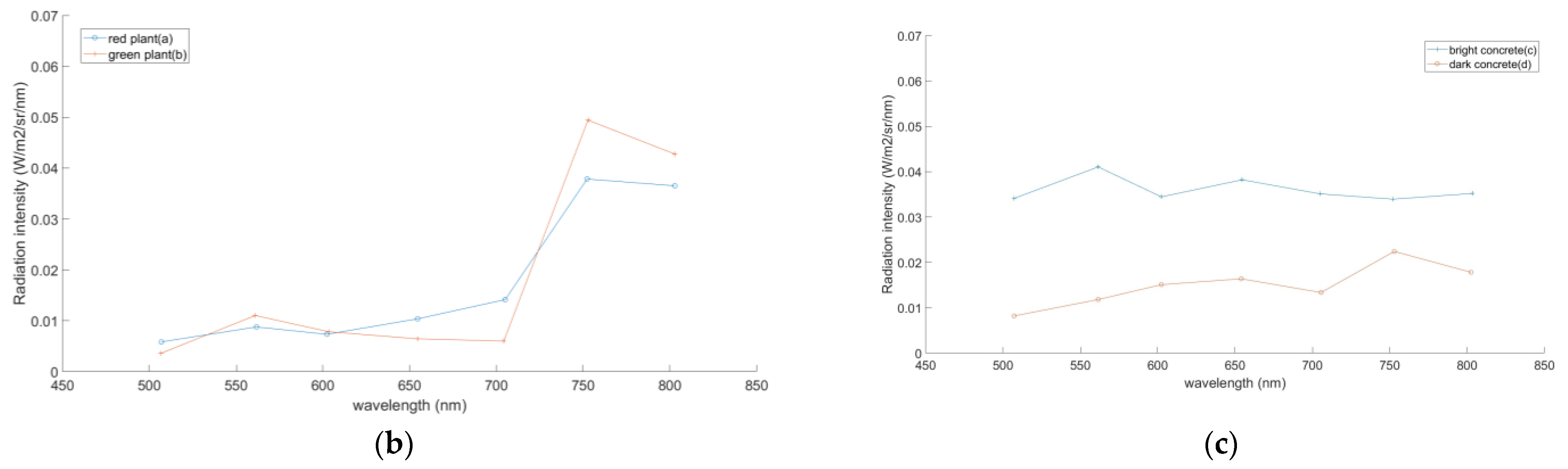
- With the spectral and radiometric calibration data, the central wavelength and the correction coefficient of all points are determined. The radiation intensity curve is solved using Equation (5).
4. Airborne Imaging Experiment
5. Results
6. Discussion
- Calibration of a large number of imaging channels. In the compound eye imaging system, normal calibration methods for array cameras perform relatively poorly because of two reasons: the low imaging resolution of each ommatidium and the hardship in the parameter optimization from the large number of the imaging channels. An appropriate calibration method for the system should give rise to a better image registration result.
- Multidimension information sensing. As the compound eye imaging system shows the capability of multispectral imaging, the system can also be used for multidimension information sensing. For example, by attaching a polarizer with different polarization angles to the ommatidia, the system can capture the polarization information of different polarization angles for navigation. This may bring on many new applications of the compound eye system.
- Lightening and miniaturizing the camera. As shown in Table 3, the BM3C achieves a large FOV and more spectrum channels than common aerial multispectral cameras but a larger volume and weight. In the future, the system will be lightened and miniaturized via multiple ways, including using lighter materials like resin for lenses and carbon fiber for the shell and using aspheric lenses for a more compact optical system.
- System application. Like other multispectral imaging devices, BM3C can be applied to fields like the parameters analyzing of crops or vegetation and the researching of biomass or biocommunities in a large area.
Author Contributions
Funding
Institutional Review Board Statement
Data Availability Statement
Conflicts of Interest
References
- Marris, E. Fly, and bring me data. Nature 2013, 498, 156–158. [Google Scholar] [CrossRef]
- Yang, G.J.; Liu, J.G.; Zhao, C.J.; Li, Z.H.; Huang, Y.B.; Yu, H.Y.; Xu, B.; Yang, X.D.; Zhu, D.M.; Zhang, X.Y.; et al. Unmanned Aerial Vehicle Remote Sensing for Field-Based Crop Phenotyping: Current Status and Perspectives. Front. Plant Sci. 2017, 8, 26. [Google Scholar] [CrossRef] [PubMed]
- Tanida, J.; Kumagai, T.; Yamada, K.; Miyatake, S.; Ishida, K.; Morimoto, T.; Kondou, N.; Miyazaki, D.; Ichioka, Y. Thin observation module by bound optics (TOMBO): An optoelectronic image capturing system. In Proceedings of the Conference on Optics in Computing 2000, Univ Laaval, Quebec City, QC, Canada, 18–23 June 2000; pp. 1030–1036. [Google Scholar]
- Zhao, Z.F.; Liu, J.; Zhang, Z.Q.; Xu, L.F. Bionic-compound-eye structure for realizing a compact integral imaging 3D display in a cell phone with enhanced performance. Optics Letters 2020, 45, 1491–1494. [Google Scholar] [CrossRef] [PubMed]
- Deng, H.X.; Gao, X.C.; Ma, M.C.; Li, Y.Y.; Li, H.; Zhang, J.; Zhong, X. Catadioptric planar compound eye with large field of view. Opt. Express 2018, 26, 12455–12468. [Google Scholar] [CrossRef] [PubMed]
- Ueno, R.; Suzuki, K.; Kobayashi, M.; Kwon, H.; Honda, H.; Funaki, H. Compound-Eye Camera Module as Small as 8.5 × 8.5 × 6.0 mm for 26 k-Resolution Depth Map and 2-Mpix 2D Imaging. IEEE Photonics J. 2013, 5, 6801212. [Google Scholar] [CrossRef]
- Duparré, J.; Dannberg, P.; Schreiber, P.; Bräuer, A.; Tünnermann, A. Artificial apposition compound eye fabricated by micro-optics technology. Appl. Optics 2004, 43, 4303–4310. [Google Scholar] [CrossRef]
- Li, L.; Yi, A.Y. Development of a 3D artificial compound eye. Opt. Express 2010, 18, 18125–18137. [Google Scholar] [CrossRef]
- Floreano, D.; Pericet-Camara, R.; Viollet, S.; Ruffier, F.; Bruckner, A.; Leitel, R.; Buss, W.; Menouni, M.; Expert, F.; Juston, R.; et al. Miniature curved artificial compound eyes. Proc. Natl. Acad. Sci. USA 2013, 110, 9267–9272. [Google Scholar] [CrossRef]
- Wu, D.; Wang, J.N.; Niu, L.G.; Zhang, X.L.; Wu, S.Z.; Chen, Q.D.; Lee, L.P.; Sun, H.B. Bioinspired Fabrication of High-Quality 3D Artificial Compound Eyes by Voxel-Modulation Femtosecond Laser Writing for Distortion-Free Wide-Field-of-View Imaging. Adv. Opt. Mater. 2014, 2, 751–758. [Google Scholar] [CrossRef]
- Shi, C.Y.; Wang, Y.Y.; Liu, C.Y.; Wang, T.S.; Zhang, H.X.; Liao, W.X.; Xu, Z.J.; Yu, W.X. SCECam: A spherical compound eye camera for fast location and recognition of objects at a large field of view. Opt. Express 2017, 25, 32333–32345. [Google Scholar] [CrossRef]
- Xu, H.R.; Zhang, Y.J.; Wu, D.S.; Zhang, G.; Wang, Z.Y.; Feng, X.P.; Hu, B.L.; Yu, W.X. Biomimetic curved compound-eye camera with a high resolution for the detection of distant moving objects. Opt. Lett. 2020, 45, 6863–6866. [Google Scholar] [CrossRef] [PubMed]
- Liu, J.H.; Zhang, Y.J.; Xu, H.R.; Yu, W.X. Large field of view 3D detection with a bionic curved compound-eye camera. In Proceedings of the Conference on AOPC-Optical Sensing and Imaging Technology, Beijing, China, 20–22 June 2021. [Google Scholar]
- Labhart, T.; Meyer, E.P. Detectors for polarized skylight in insects: A survey of ommatidial specializations in the dorsal rim area of the compound eye. Microsc. Res. Tech. 1999, 47, 368–379. [Google Scholar] [CrossRef]
- Awata, H.; Wakakuwa, M.; Arikawa, K. Evolution of color vision in pierid butterflies: Blue opsin duplication, ommatidial heterogeneity and eye regionalization in Colias erate. J. Comp. Physiol. A-Neuroethol. Sens. Neural Behav. Physiol. 2009, 195, 401–408. [Google Scholar] [CrossRef] [PubMed]
- Tanida, J.; Shogenji, R.; Kitamura, Y.; Yamada, K.; Miyamoto, M.; Miyatake, S. Color imaging with an integrated compound imaging system. Opt. Express 2003, 11, 2109–2117. [Google Scholar] [CrossRef]
- Miyatake, S.; Shogenji, R.; Miyamoto, M.; Nitta, K.; Tanida, J. Thin observation module by bound optics (TOMBO) with color filters. In Proceedings of the Conference on Sensors and Camera Systems for Scientific, Industrial, and Digital Photography Applications V, San Jose, CA, USA, 19–21 January 2004; pp. 7–12. [Google Scholar]
- Mathews, S.A. Design and fabrication of a low-cost, multispectral imaging system. Appl. Optics 2008, 47, F71–F76. [Google Scholar] [CrossRef]
- Kagawa, K.; Fukata, N.; Tanida, J. High-speed multispectral three-dimensional imaging with a compound-eye camera TOMBO. In Optics and Photonics for Information Processing IV; SPIE: Bellingham, DC, USA, 2010; Volume 7797. [Google Scholar] [CrossRef]
- Shogenji, R.; Kitamura, Y.; Yamada, K.; Miyatake, S.; Tanida, J. Multispectral imaging system by compact compound optics. In Proceedings of the Conference on Nano- and Micro-Optics for Information Systems, San Diego, CA, USA, 3–4 August 2003; pp. 93–100. [Google Scholar]
- Kagawa, K.; Yamada, K.; Tanaka, E.; Tanida, J. A three-dimensional multifunctional compound-eye endoscopic system with extended depth of field. Electr. Commun. Jpn. 2012, 95, 14–27. [Google Scholar] [CrossRef]
- Yoshimoto, K.; Yamada, K.; Sasaki, N.; Takeda, M.; Shimizu, S.; Nagakura, T.; Takahashi, H.; Ohno, Y. Evaluation of a compound eye type tactile endoscope. In Proceedings of the Conference on Endoscopic Microscopy VIII, San Francisco, CA, USA, 3–4 February 2013. [Google Scholar]
- Nakanishi, T.; Kagawa, K.; Masaki, Y.; Tanida, J. Development of a Mobile TOMBO System for Multi-spectral Imaging. In Proceedings of the Fourth International Conference on Photonics Solutions, Chiang Mai, Thailand, 20–22 November 2020; Volume 11331. [Google Scholar] [CrossRef]
- Yu, X.D.; Liu, C.Y.; Zhang, Y.J.; Xu, H.R.; Wang, Y.Y.; Yu, W.X. Multispectral curved compound eye camera. Opt. Express 2020, 28, 9216–9231. [Google Scholar] [CrossRef]
- Zhang, Y.J.; Xu, H.R.; Guo, Q.; Wu, D.S.; Yu, W.X. Biomimetic multispectral curved compound eye camera for real-time multispectral imaging in an ultra-large field of view. Opt. Express 2021, 29, 33346–33356. [Google Scholar] [CrossRef]
- Blackburn, G.A. Hyperspectral remote sensing of plant pigments. J. Exp. Bot. 2007, 58, 855–867. [Google Scholar] [CrossRef]
- Liu, J.H.; Zhang, Y.J.; Xu, H.R.; Wu, D.S.; Yu, W.X. Long-working-distance 3D measurement with a bionic curved compound-eye camera. Opt. Express 2022, 30, 36985–36995. [Google Scholar] [CrossRef]
- Hossein-Nejad, Z.; Nasri, M. Image Registration based on SIFT Features and Adaptive RANSAC Transform. In Proceedings of the IEEE International Conference on Communication and Signal Processing (ICCSP), Melmaruvathur, India, 6–8 April 2016; pp. 1087–1091. [Google Scholar]
- Shogenji, R.; Kitamura, Y.; Yamada, K.; Miyatake, S.; Tanida, J. Multispectral imaging using compact compound optics. Opt. Express 2004, 12, 1643–1655. [Google Scholar] [CrossRef] [PubMed]
- Jin, J.; Di, S.; Yao, Y.; Du, R. Design and fabrication of filtering artificial-compound-eye and its application in multispectral imaging. In Proceedings of the ISPDI 2013-Fifth International Symposium on Photoelectronic Detection and Imaging, Beijing, China, 23 August 2013. [Google Scholar]
- Chen, J.; Lee, H.H.; Wang, D.; Di, S.; Chen, S.-C. Hybrid imprinting process to fabricate a multi-layer compound eye for multispectral imaging. Opt. Express 2017, 25, 4180–4189. [Google Scholar] [CrossRef] [PubMed]


| Parameter | Designed Value | Tested Value |
|---|---|---|
| Number of ommatidia | 169 | 169 |
| System focal length (mm) | 2.7 | 2.76 |
| Maximum FOV (degrees) | 120 | 127.4 |
| Central wavelengths (nm) | 500, 560, 600, 650, 700, 750, 800 | 506, 560, 602, 653, 704, 751, 801 |
| Spectral resolution (nm) | 10 | 11.6 |
| Maximum framerate (fps) | 13 | 13 |
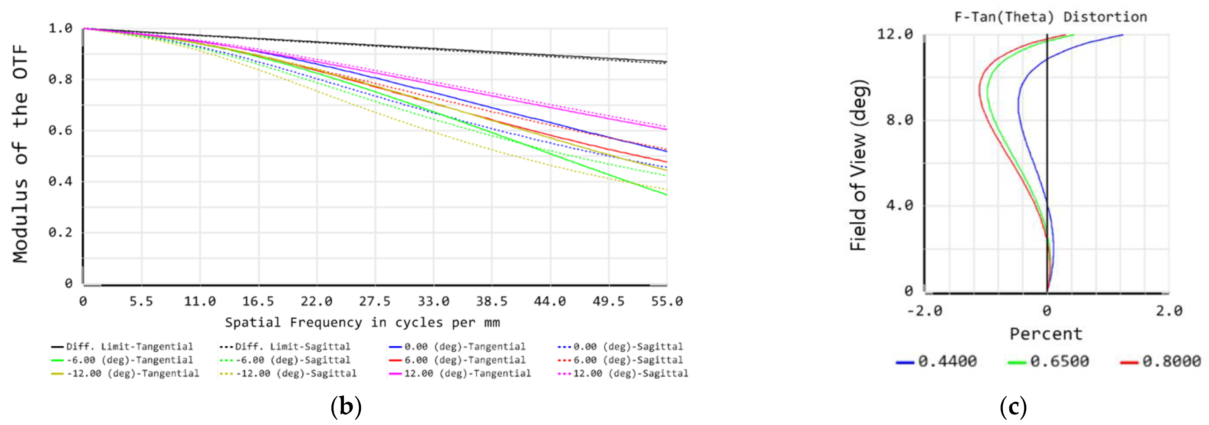
| Distortion | <2% | <1.78% |
| Ideal Wavelength | Ring 1 | Ring 2 | Ring 3 | Ring 4 | Ring 5 |
|---|---|---|---|---|---|
| 500 | 507.5 | 507.1 | 506.5 | 505.5 | 504.4 |
| 560 | 561.7 | 561.3 | 560.5 | 559.3 | 557.9 |
| 600 | 603.6 | 603.0 | 602.1 | 600.7 | 599.1 |
| 650 | 654.9 | 654.3 | 653.3 | 651.7 | 649.9 |
| 700 | 705.9 | 705.4 | 704.3 | 702.9 | 701.1 |
| 750 | 752.9 | 752.3 | 751.3 | 749.7 | 747.9 |
| 800 | 803.5 | 802.9 | 801.7 | 800.1 | 798.1 |
| Product Model | Size/mm | Weight/g | Bands | Wavelengths/ nm | Resolution/ Pixels | FOV/Degrees | Power/W |
|---|---|---|---|---|---|---|---|
| Micasense RedEdge | 120 × 70 × 50 | 180 | 5 | 475, 560, 668, 717, 840 | 1280 × 960 | 47.2 × 35.4 | 4 |
| Parrot Sequoia | 59 × 41 × 28 | 135 | 4 | 550, 660, 735, 790 | 1280 × 960 | 61.9 × 48.5 | 8 |
| Tetracam MCA6 | 116 × 80 × 68 | 580 | 6 | 490, 550, 680, 720, 800, 900 | 1280 × 1024 | 38.3 × 31.0 | 9.8 |
| ADC lite | 114 × 77 × 61 | 200 | 3 | 560, 660, 840 | 2048 × 1536 | 44.5 × 34.8 | 2 |
| BM3C | 194 × 194 × 232 | 2492 | 7 | 506, 560, 602, 653, 704, 751, 801 | 5120 × 5120 | Max. 127.4 | 6 |
| System | Focal Length (mm) | FOV (Degree) | Wavebands | Number of Units |
|---|---|---|---|---|
| TOMBO (2004) [29] | 1.3 | / | 7 | 16 |
| TOMBO (2010) [19] | 2.35 | 16 × 16 | 2 | 25 |
| Planar multispectral ACE [30] | / | / | 4 | 36 |
| Multi-layer compound eye [31] | / | / | 4 | 12 |
| TOMBO (2020) [23] | 1.5 | 50 × 50 | 8 | 9 |
| BM3C | 2.76 | Max.127.4 | 7 | 169 |
Disclaimer/Publisher’s Note: The statements, opinions and data contained in all publications are solely those of the individual author(s) and contributor(s) and not of MDPI and/or the editor(s). MDPI and/or the editor(s) disclaim responsibility for any injury to people or property resulting from any ideas, methods, instructions or products referred to in the content. |
© 2023 by the authors. Licensee MDPI, Basel, Switzerland. This article is an open access article distributed under the terms and conditions of the Creative Commons Attribution (CC BY) license (https://creativecommons.org/licenses/by/4.0/).
Share and Cite
Zhang, Y.; Xu, H.; Liu, Y.; Zhou, X.; Wu, D.; Yu, W. Advanced Biomimetic Multispectral Curved Compound Eye Camera for Aerial Multispectral Imaging in a Large Field of View. Biomimetics 2023, 8, 556. https://doi.org/10.3390/biomimetics8070556
Zhang Y, Xu H, Liu Y, Zhou X, Wu D, Yu W. Advanced Biomimetic Multispectral Curved Compound Eye Camera for Aerial Multispectral Imaging in a Large Field of View. Biomimetics. 2023; 8(7):556. https://doi.org/10.3390/biomimetics8070556
Chicago/Turabian StyleZhang, Yuanjie, Huangrong Xu, Yiming Liu, Xiaojun Zhou, Dengshan Wu, and Weixing Yu. 2023. "Advanced Biomimetic Multispectral Curved Compound Eye Camera for Aerial Multispectral Imaging in a Large Field of View" Biomimetics 8, no. 7: 556. https://doi.org/10.3390/biomimetics8070556