Article

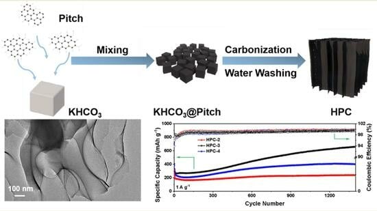
Green Synthesis of Hierarchically Porous Carbon Derived from Coal Tar Pitch for Enhanced Lithium Storage

State Key Laboratory of Heavy Oil Processing, Advanced Chemical Engineering and Energy Materials Research Center, College of New Energy, China University of Petroleum (East China), Qingdao 266580, China
*
Authors to whom correspondence should be addressed.
Batteries 2023, 9(9), 473; https://doi.org/10.3390/batteries9090473
Submission received: 1 August 2023 / Revised: 7 September 2023 / Accepted: 18 September 2023 / Published: 19 September 2023
(This article belongs to the Special Issue Advanced Carbon-Based Materials for Batteries)

Abstract

:
Coal tar pitch (CTP) is a high-quality raw material for producing functional carbon materials owing to its high carbon yield and high degree of condensation. The rational structure regulation of CTP-derived carbon materials is paramount for their special application. Herein, a green template strategy is proposed to fabricate hierarchically porous carbon (HPC) and employ it as the anode material for lithium-ion batteries. It can be demonstrated that the mass ratio of the template (KHCO3) and carbon source (CTP) significantly influences the microstructure and electrochemical performances of HPC. HPC-3 synthesized by a mass ratio of 3:1 shows a coral-like lamellar nanostructure with high specific surface area, developed nanopores, and ample defects, enabling fast and high-flux lithium storage. Thus, the HPC-3 electrode achieves an excellent rate capacity of 219 mAh g−1 at 10 A g−1 and maintains a high discharge capacity of 660 mAh g−1 after 1400 cycles at 1 A g−1. This work takes a step towards the high-value-added and green utilization of CTP and offers a promising solution for the sustainable production of advanced carbon electrode materials.

Graphical Abstract

1. Introduction

A profound global energy transformation is in progress because of the gradual depletion and environmental issues of traditional fossil energy sources. The burgeoning development of renewable energy has massively accelerated the need for electrochemical energy storage (EES) technologies, which play considerable and indispensable roles in eliminating the intermittent and regional limitations of renewable energy. Among various EES technologies, the rechargeable battery has been considered the most successful technology because of its environmental friendliness, cost-effectiveness, and application flexibility [1,2]. Lithium-ion batteries (LIBs) have achieved a leap-forward development in the portable electronics market over the past few decades, with a rapid spread to the markets of electric vehicles and even stationary energy storage systems [3,4]. The LIBs have numerous merits, including high energy density, low self-discharge, and long lifespan. In order to meet the current demand for power supplies, there is still a need to pursue higher performance indicators for LIBs, including improved energy density, prolonged lifespan, high power output, high safety, and low cost. These are all intimately correlative to the properties of electrode materials [5,6].
Graphite, as the dominant anode material for commercial LIBs, is far from satisfactory. It exhibits a low theoretical capacity of 372 mAh g−1, and the intercalation of lithium into a graphite host suffers from a sluggish diffusion-controlled process, leading to a limited rate capability. In addition, because of the low average de-/lithiation potential, metallic lithium dendritic is prone to be precipitated on the anode surface, which will result in the degradation of battery performances and some safety issues [7,8]. Therefore, more efforts should be devoted to exploring desirable anode materials. It has been widely demonstrated that a variety of carbon nanomaterials, such as graphene [9,10,11], carbon nanotubes [12,13,14,15], porous carbon [16,17], and heteroatom-doped carbon [18,19,20,21], can effectively improve the specific capacity, rate capability, and cycling stability of LIBs. In particular, two-dimensional (2D) porous carbon nanomaterials featuring a high specific surface area and developed pore structure are very favorable for shortening the transport distance of lithium ions and accelerating the interfacial kinetics, thus holding great potential as fast-charging electrode materials [22,23,24].
The choice of raw materials and synthesis methods is vital to modulating the microstructure and the relevant electrochemical performances of carbon anode materials. Coal tar pitch (CTP) is a bulk by-product of the coal coking process and has relatively limited applications, mainly as road and building materials, which suffer from low added value and waste of resources. Regarding the molecule level, CTP mainly consists of a polycyclic aromatic nucleus and alkyl side chains [25]. The CTP molecules can be easily rearranged into carbon through “bottom-up” chemical means. Therefore, it is an attractive way to motivate the high value-added utilization of CTP as a carbon precursor, which has the advantages of high carbon yield, low cost, and abundant resources [26,27]. Currently, the commonly used methods for preparing CTP-derived carbon encompass template methods [28,29,30] and chemical activation methods [31,32,33]. For example, He and his co-workers proposed a strategy of the nano-ZnO template coupled with KOH activation to prepare CTP-derived three-dimensional interconnected graphene nanocapsules [29]. Xing et al. developed porous graphitic carbons from CTP using CaCO3 nanoparticles as a template and activating agent [30]. Yang et al. first introduced oxygen functional groups into CTP to induce the crosslinking and condensation between oxidized CTP molecules and then carried out the carbonization–KOH activation process to obtain oxygen-rich hierarchical porous carbons [32]. Although substantial research has been performed, the preparation methods usually involve tedious preparation procedures and toxic or corrosive reagents. From a sustainable development perspective, developing facile, green, and controllable routes to CTP-derived porous carbon is long-sought-after.
This work successfully fabricated hierarchically porous carbon (HPC) using CTP as the carbon precursor and KHCO3 as the template. The KHCO3 template is not only responsible for the formation of hierarchical pores but also induces the construction of coral-like lamellar structures. Notably, the KHCO3 template and its derivatives can be removed by mild water washing, complying with the green and sustainable design concept. Furthermore, we systematically investigated the regulation laws of the template and CTP mass ratio on the HPC microstructure and the structure–performance relationship of HPC anode materials. It was found that the HPC material synthesized via a mass ratio of 3:1 (HPC-3) shows comprehensive advantages, including a well-designed coral-like framework, high specific surface area, a hierarchically porous structure, and a high disorder and defect degree. When used as the anode material for LIBs, HPC-3 exhibits a high rate capability (219 mAh g−1 at 10 A g−1) and a good cycling performance (660 mAh g−1 after 1400 cycles at 1 A g−1).

2. Experimental

2.1. Chemicals

CTP with a softening point of 85 °C, 2–3 wt.% of quinoline insolubles, and 15 wt.% of toluene insolubles was purchased from Ansteel Co., Ltd. (Liaoning, China). KHCO3 (purity ≥ 99.5%) and N-methylpyrrolidone (NMP, purity ≥ 99.5%) were purchased from Sinopharm Chemical Reagent Co., Ltd. (Shanghai, China). Acetylene carbon black (purity ≥ 99.5%) and polypropylene separator (PP, Celgard 2500) were purchased from Aowei Technology Co., Ltd. (Shanghai, China). Polyvinylidene fluoride (PVDF, purity ≥ 98%) was purchased from Sigma–Aldrich (Burlington, Massachusetts, USA). Copper foil with a thickness of ~9 μm was purchased from Hefei Kejing Co., Ltd. (Hefei, China). Lithium foil (purity ≥ 99.9%) from China Energy Lithium Co., Ltd. (Tianjin, China). The electrolyte containing 1M LiPF6 dissolved in an equal volume mixture of ethylene carbonate, dimethyl carbonate, and ethyl methyl carbonate with 2 wt% of fluoroethylene carbonate additive was purchased from DoDo Chem.

2.2. Synthesis of HPC

The HPC materials were fabricated from CTP via a KHCO3 template method. In detail, CTP and KHCO3 were evenly mixed via grinding in a mass ratio of 2:1, 3:1, and 4:1, respectively. The obtained mixture was then heated to 800 °C with a heating rate of 5 °C min−1 and held for 2 h under a N2 atmosphere. After cooling to room temperature, the carbonized product was washed with deionized water, filtrated, and dried in a vacuum oven at 60 °C for 24 h. The resulting sample was denoted as HPC-X, where X represents the mass ratio of KHCO3 to CTP (X = 2, 3, and 4).

2.3. Material Characterizations

The micromorphology was investigated via a scanning electron microscope (SEM, Regulus8200, Hitachi, Tokyo, Japan) and transmission electron microscope (TEM, JEM-2100F, JEOL Ltd., Tokyo, Japan). The crystalline structure was measured via X-ray diffraction (XRD, X’ Pert Pro MPD system, PANalytical, Alemlo, Netherland). Raman spectra were obtained on a LabRAM HR Evolution Raman spectrometer. N2 adsorption and desorption measurements were performed on an ASAP 2020 PLUS instrument to measure the surface area and pore structure. The surface chemical composition was detected via X-ray photoelectron spectroscopy (XPS, Thermo Scientific ESCALab220i-XL, Thermo Fisher Scientific, Waltham, MA, USA).

2.4. Electrochemical Measurements

The HPC-X powder, conductive additives (acetylene carbon black), and binder (PVDF) were mixed in an appropriate amount of NMP solvent in a mass ratio of 8:1:1. The slurry was then cast onto the copper foil and dried at 80 °C for 12 h. After cutting, an electrode sheet with a diameter of 12 mm was obtained. The mass loading of the active material was about 0.6 mg cm−2. The electrochemical performances were measured in a half-cell configuration. CR2032 coin-type cells were assembled in an argon-filled glovebox (Etelux Lab2000, Etelux, Beijing, China, H2O < 0.1 ppm and O2 < 0.1 ppm). The as-fabricated HPC electrode sheet was used as the working electrode, lithium foil was used as the reference electrode and counter electrode, and the PP separator was the electron battier between the two electrodes. A total of 40 μL of electrolyte was added dropwise to the HPC and lithium electrode sides, respectively. The galvanostatic charge–discharge (GCD) tests were performed on the Land CT2001A battery test instrument in the voltage range of 0.0–3.0 V. The cyclic voltammetry (CV) measurement at various scan rates and electrochemical impedance spectroscopy (EIS, 100 kHz–10 mHz) were conducted on the CHI760D electrochemical workstation.

3. Results and Discussion

The low-cost and green synthesis strategy of HPC is schematically shown in Figure 1. CTP was used as the carbon precursor, and KHCO3 functioned as the template and activation agent. It can be observed from the SEM images (Figure S1) that the original CTP shows a blocky morphology with a scaly surface, indicating that it is a promising precursor for lamellar carbon nanomaterials. During the heat treatment of the mixture of CTP and KHCO3, KHCO3 was first decomposed into K2CO3, which is responsible for forming the coral-like laminar structure. Then, K2CO3 would be further decomposed and reacted with carbon atoms, resulting in gas release and the formation of micropores and mesopores [34]. Finally, the residual K2CO3 and other K-containing species were removed via facile water washing, avoiding the use of toxic or corrosive reagents.
The mass ratio of KHCO3 and CTP significantly affects the microstructure of HPC. As shown in the SEM images of HPC-3 (Figure 2a,b), it presents a coral-like skeleton formed via the oriented arrangement of two-dimensional carbon lamella, which is conducive to exposing more surface accessible for electrolyte and shortening the diffusion path of lithium ions. The EDS elemental mapping and the EDS spectrum of the HPC-3 sample are shown in Figure S2. It can be found that the C element is dominant in HPC-3, while the content of the K element is negligible at only 0.02 at%, indicative of the successful removal of K-related compounds in the carbon material. It can be further observed from the TEM image (Figure 2c) that there are many nanopores on the surface of lamellar HPC-3, which is beneficial for the transport of electrolytes and the adsorption of lithium ions. The high-resolution TEM (HR-TEM) image (Figure 2d) shows ordered lattice fringes in short range with a lattice spacing of 0.38 nm, which is much larger than that of graphite (0.34 nm). The defect-rich microcrystalline structure and the expanded lattice spacing are favorable for lithium ions’ adsorption and intercalation/deintercalation, thus contributing to high lithium storage capacity [35,36,37]. For comparison, the micromorphology of HPC-2 and HPC-4 was also observed via SEM characterization (Figure S3). As seen from Figure S3a and b, HPC-2 displays irregular blocky accumulations, indicating that the dosage of KHCO3 is insufficient to effectively regulate the microstructure of CTP-derived carbon. In the case of excessive KHCO3 (Figure S3c,d), the coral-like skeleton of HPC-4 is disrupted and collapsed owing to the severe etching of the carbon matrix via K-containing activators. With this information in mind, it can be demonstrated that an appropriate mass ratio of a template to carbon precursor is essential to rationally control the micromorphology and microstructure of carbon materials.
The structure and composition of HPC-X were further investigated via XRD, Raman spectra, nitrogen adsorption experiment, and XPS characterization. From the XRD patterns of three samples (Figure 3a), two broad and weak peaks located at ca. 24° and 43° can be recognized, corresponding to the characteristic peaks of (002) and (100) lattice planes of graphitic structure, respectively [27]. The spacing of (002) lattice planes of three samples can be determined based on the Bragg equation:
2d002sinθ =
where d002 refers to the lattice spacing (nm), θ refers to the angle (°) between the incident X-ray and the (002) crystal plane, n refers to the diffraction order (n = 1), and λ refers to the wavenumber of incident X-ray (λ = 0.15406 nm). The calculated results are summarized in Table 1. The interlayer spacing of HPC-2, HPC-3, and HPC-4 is 0.378, 0.382, and 0.380 nm, respectively, suggesting that the KHCO3 template can effectively regulate the microcrystalline arrangement structure of HPC-X, and thus modulate the intercalation and deintercalation behavior of lithium ions between graphite layers. Figure 3b displays the Raman spectra of three samples. The peak at ca. 1350 cm−1 corresponds to the disorder-related D band, and the peak at ca. 1589 cm−1 is assigned to the sp2-hybridized G band [38]. The strength ratio (ID/IG) between the D and G bands is usually used to assess the degree of defect and disorder in carbon materials. As listed in Table 1, the ID/IG values of HCP-2, HPC-3, and HCP-4 are 0.91, 0.97, and 0.94, respectively, demonstrating that HCP-3 has more defects and thus can provide more adsorption sites for lithium ions.
The N2 adsorption–desorption isotherms of HPC-X are shown in Figure 3c. As can be recognized from the Bruno–Emmett–Taylor and density functional theory model calculation results (Table 1), with the increase of the mass ratio of KHCO3 and CTP, the specific surface area and pore volume of HPC-X first increase and then decrease, which is attributed to the fact that less template has limited effect on the modulation of lamellar morphology and pore structure. In contrast, excessive templates would severely etch the carbon matrix and cause the collapse of pores. HPC-3 has the highest specific surface area (1643 m2 g−1) and pore volume (0.99 cm3 g−1), which can increase the contact interface between the electrode and electrolyte and accelerate the mass transport. As demonstrated by the pore size distribution curves (Figure 3d) and pore structure parameters (Table 1), HCP-2 and HCP-4 are dominated by micropores, whereas HPC-3 possesses a hierarchical pore structure, and the mesopores with the pore size in the range of 2~5 nm are significantly increased, which is more favorable for the fast diffusion of electrolyte and lithium ions. The full XPS spectra (Figure 3e) confirm that all HPC-X samples mainly comprise C and O elements; the corresponding element contents are listed in Table S1. The trace amount of elemental N originated from the raw CTP. The C 1s and O 1s peaks of HPC-X were further fitted and analyzed. As shown in the high-resolution XPS spectra of C 1s in HPC-3 (Figure S4a), the peaks at 284.6, 285.4, 287.3, and 288.3 eV can be assigned to sp2 C=C, C-O/C-N, C=O, and O=C-O bonding, respectively. The high-resolution XPS spectra of the O 1s peak in HPC-3 (Figure 3f) can be deconvoluted into four subpeaks: C=O (530.7 eV), O-C-O/C-OH (531.9 eV), -O-C=O (533.0 eV), and -COOH (534.2 eV) [39]. These surface functional groups can significantly increase HPC-X’s wettability and accelerate electrolyte penetration and transport [40]. The analysis results for C 1s and O 1s peaks of HPC-2 and HPC-4 are similar to the above explanation (Figure S4b–e). All the characterization results fully reveal that the lamellar HPC-3 has comprehensive superiority, including ultrahigh specific surface area, abundant micropores and mesopores, as well as a high degree of disorder caused by lattice defects and O heteroatom doping, and thus is expected to achieve high and fast lithium storage.
The electrochemical performances of HPC-X were evaluated in a half-cell configuration. Figure 4a displays the CV curves of HPC-3 in the voltage range of 0.01–3 V at a scan rate of 0.2 mV s−1. Three obvious reduction peaks are present during the first discharge. The irreversible peaks at ca. 1.7 and 0.7 V can be ascribed to the formation of solid electrolyte interphase (SEI) film and the decomposition of electrolyte [41]. The reversible reduction peak at ca. 0.01 V accounts for the insertion of lithium ions into the graphite domain and nanopores. The CV curves almost overlap during the subsequent cycles, manifesting that the formed SEI film is stable. Figure 4b shows the GCD curves of HPC-3 in the initial three cycles at a current density of 0.1 A g−1. In accordance with the CV curves, a blurry high-discharge plateau is present in the initial discharge but disappears in the following cycles, which can be attributable to the formation of SEI film and irreversible side reactions [42].
The GCD curves maintain a good consistency during the subsequent cycles. The discharge curve can be divided into two regions: a slope region corresponding to the adsorption of lithium ions on the surface and defect sites of HPC-3 and a low-plateau region corresponding to the interlayer intercalation and nanopore filling of lithium ions. The charge curve corresponds to the reverse electrochemical process. The rate performances of HPC-X are shown in Figure 4c. At a low current density of 0.1 A g−1, the initial discharge specific capacities of HPC-2, HPC-3, and HPC-4 anode materials are 541.8, 1066.8, and 522.5 mAh g−1, respectively, and the corresponding initial coulombic efficiency (ICE) is 47.5%, 49.1%, and 47.0%, respectively. The low ICE is a common failing for carbon electrode materials and is closely related to the specific surface area, pore size, and surface functional groups [30,43]. Although the larger specific surface area of HPC-3 adversely affects the ICE, this effect is offset by fewer O-containing functional groups and wider pore size distribution. With the increase of current density, the discharge-specific capacities of all anode materials gradually decrease. Despite this, HPC-3 consistently affords significantly higher capacity. At a current density of 0.2, 0.5, 1.0, 2.0, 5.0, and 10.0 A g−1, the discharge-specific capacities of HPC-3 are 792, 563, 415, 333, 258, and 219 mAh g−1, respectively. In addition, most of the specific capacity can still be restored when the current density is back to 0.2 A g−1, indicative of a high reversibility. By comparison with the GCD curves of HPC-X at different current densities (Figure S5a–c), it is apparent that the polarization phenomenon of HPC-2 and HPC-4 is more and more serious with the increase of current densities, but HPC-3 still retains good charge–discharge behavior even at high current densities, which is attributed to the fact that the aligned channels within the coral-like skeleton and the abundant nanopores on the lamella surface provide smooth routes for the fast transport of lithium ions. The cycling performances of HCP-X anode materials at a current density of 1 A g−1 are shown in Figure 4d. During the first few hundred cycles, the capacity of the HPC-X increases because more electrolyte ions gradually infiltrate into the meso- and micropores of the carbon materials [43], which can be revealed via the increase of capacity contribution at the low-plateau region with the cycling, as shown in the GCD curves during cycles (Figure S6). After 1400 cycles, the discharge-specific capacities of HPC-2, HPC-3, and HPC-4 are 239, 660, and 401 mAh g−1, respectively.
The HCP-3 shows a higher capacity and better cycling performance, demonstrating that the well-developed porous network and a wealth of defects provide enough active sites for high-volume lithium storage. The capacity increase phenomenon is absent when the cell is discharged/charged at a low current density of 0.2 A g−1 (Figure S7). The capacity of HPC-3 gradually decreases in the first 10 cycles and remains relatively stable in subsequent cycles. The EIS curves of HPC-X are displayed in Figure 4e. There is a depressed semicircle in the high-to-medium frequency region and an inclined line in the low-frequency region, corresponding to the charge transfer resistance and the diffusion resistance of lithium ions, respectively [44,45]. In contrast with HPC-2 and HPC-4, HPC-3 shows a smaller semicircle and a smaller slope of the inclined line, indicative of faster electron and ion transport. These outstanding electrochemical performances of HPC-3 can be credited to its structure merits. On the one hand, the large specific surface area and expanded lattice distance shorten the transport route of electrolyte and lithium ions and accelerate the diffusion kinetics of lithium ions into graphite layers. On the other hand, the hierarchically microporous and mesoporous structure and abundant defects increase storage and adsorption sites for lithium ions. Furthermore, we compared the preparation strategy and cycling performance of HPC-3 with those of previously reported carbon anode materials. As listed in Table 2, HPC-3 shows overwhelming superiorities as the anode material for LIBs. The low cost, simplicity, and environmental friendliness of its preparation strategy and its marvelous cycling performance demonstrate great potential for large-scale application.
In order to gain a deep insight into the energy storage mechanism of HPC-3, its CV curves were tested within the potential range of 0.01–3 V at different scan rates. As depicted in Figure 5a, with the increase in scan rate, the cathodic peak and the anodic peak slightly shift toward low and high potential, respectively, indicating a small polarization. The relationship between peak current (i) and scan rate (ν) is according to the following equation [49,50]:
i v = a v b
log i v = log a + b log v
where a and b are adjustable constants. Generally, the charge storage mechanism is divided into the capacitive behavior with faster kinetics and the diffusion-controlled behavior with slower kinetics. If the b value is 0.5, the electrochemical process is controlled by the ionic diffusion, whereas if the b value is 1, the electrochemical process is controlled by surface capacitive behavior. In this regard, the charge storage mechanism can be qualitatively distinguished via linearly fitting log (i) versus log (ν). It can be seen from Figure 5b that the values of b for the cathodic and anodic peaks are 0.87 and 0.74, respectively, indicating that the capacitive contribution is dominant. Such a high capacitive contribution can effectively improve the rate and cycling performances of LIBs [51,52].

4. Conclusions

In summary, a simple, green, and cost-effective route is presented to synthesize CTP-derived HPC anode materials for high-performance LIBs. The micromorphology and structure of HPC were effectively regulated by adjusting the mass ratio of the KHCO3 template and CTP. The obtained HPC-3 presents a coral-like lamellar structure with a specific surface area as high as 1643 m2 g−1 and a pore volume up to 0.99 cm3 g−1, which can effectively enlarge the contact interface between the electrode and electrolyte and propel the diffusion kinetics of lithium ions. There are also many structural defects induced by the intrinsic lattice disorder and the introduction of O heteroatom in HPC-3, endowing sufficient space and active sites for lithium storage. As a result, the HPC-3 electrode achieves an excellent rate capacity of 219 mAh g−1 at 10 A g−1 and maintains a high reversible capacity of 660 mAh g−1 after 1400 cycles at 1 A g−1. This work takes a step towards the high value-added and green utilization of coal tar pitch and provides a desirable candidate for advanced carbon anode materials.

Supplementary Materials

The following supporting information can be downloaded at https://www.mdpi.com/article/10.3390/batteries9090473/s1. Figure S1: SEM images of CTP; Figure S2: SEM image and the corresponding EDS elemental mapping of HPC-3. Figure S3: SEM images of HPC-2 and HPC-4; Figure S4: High-resolution XPS spectra of C 1s in HPC-2, HPC-3, and HPC-4 and O 1s in HPC-2 and HPC-4; Figure S5: GCD profiles of HPC-2, HPC-3, and HPC-4; Figure S6: GCD profiles of HPC-2, HPC-3, and HPC-4 during cycling; Figure S7: Cycling performance of HPC-3 at a current density of 0.2 A g−1; Table S1: Element contents and O element configuration in HPC-X.

Author Contributions

M.Z.: conceptualization, methodology, investigation, and writing—original draft. M.Q. and W.Y.: investigation and data curation. J.M. and Z.H.: writing—review and editing. M.W.: supervision and resources. All authors have read and agreed to the published version of the manuscript.

Funding

This work was supported by the National Natural Science Foundation of China (22005341 and 22138013), the Shandong Provincial Natural Science Foundation (ZR2020QB128 and ZR2020ZD08), the Taishan Scholar Project (tsqnz20221121 and ts201712020), the Major Scientific and Technological Innovation Project of Shandong Province (2020CXGC010402), the ShanDong Energy Group CO., LTD., Technology Project (YKKJ2019AJ08JG-R63), and the Independent Innovation Research Project of China University of Petroleum (22CX06026A).

Data Availability Statement

Not applicable.

Conflicts of Interest

The authors declare no conflict of interest.

References

  1. Larcher, D.; Tarascon, J.M. Towards Greener and More Sustainable Batteries for Electrical Energy Storage. Nat. Chem. 2015, 7, 19–29. [Google Scholar] [CrossRef] [PubMed]
  2. Gur, T.M. Review of Electrical Energy Storage Technologies, Materials and Systems: Challenges and Prospects for Large-Scale Grid Storage. Energy Environ. Sci. 2018, 11, 2696–2767. [Google Scholar] [CrossRef]
  3. Cano, Z.P.; Banham, D.; Ye, S.; Hintennach, A.; Lu, J.; Fowler, M.; Chen, Z. Batteries and Fuel Cells for Emerging Electric Vehicle Markets. Nat. Energy 2018, 3, 279–289. [Google Scholar] [CrossRef]
  4. Li, M.; Lu, J.; Chen, Z.; Amine, K. 30 Years of Lithium-Ion Batteries. Adv. Mater. 2018, 30, 1800561. [Google Scholar] [CrossRef]
  5. Li, L.; Zhang, D.; Deng, J.; Gou, Y.; Fang, J.; Cui, H.; Zhao, Y.; Cao, M. Carbon-Based Materials for Fast Charging Lithium-Ion Batteries. Carbon 2021, 183, 721–734. [Google Scholar] [CrossRef]
  6. Xie, L.; Tang, C.; Bi, Z.; Song, M.; Fan, Y.; Yan, C.; Li, X.; Su, F.; Zhang, Q.; Chen, C. Hard Carbon Anodes for Next-Generation Li-Ion Batteries: Review and Perspective. Adv. Energy Mater. 2021, 11, 2101650. [Google Scholar] [CrossRef]
  7. Long, W.; Fang, B.; Ignaszak, A.; Wu, Z.; Wang, Y.-J.; Wilkinson, D. Biomass-Derived Nanostructured Carbons and Their Composites as Anode Materials for Lithium Ion Batteries. Chem. Soc. Rev. 2017, 46, 7176–7190. [Google Scholar] [CrossRef]
  8. Asenbauer, J.; Eisenmann, T.; Kuenzel, M.; Kazzazi, A.; Chen, Z.; Bresser, D. The Success Story of Graphite as a Lithium-Ion Anode Material-Fundamentals, Remaining Challenges, and Recent Developments Including Silicon (Oxide) Composites. Sustain. Energ. Fuels 2020, 4, 5387–5416. [Google Scholar] [CrossRef]
  9. Hassoun, J.; Bonaccorso, F.; Agostini, M.; Angelucci, M.; Betti, M.G.; Cingolani, R.; Gemmi, M.; Mariani, C.; Panero, S.; Pellegrini, V.; et al. An Advanced Lithium-Ion Battery Based on a Graphene Anode and a Lithium Iron Phosphate Cathode. Nano Lett. 2014, 14, 4901–4906. [Google Scholar] [CrossRef]
  10. Xing, Z.; Ju, Z.; Zhao, Y.; Wan, J.; Zhu, Y.; Qiang, Y.; Qian, Y. One-Pot Hydrothermal Synthesis of Nitrogen-Doped Graphene as High-Performance Anode Materials for Lithium Ion Batteries. Sci. Rep. 2016, 6, 26146. [Google Scholar] [CrossRef]
  11. Kumar, R.; Sahoo, S.; Joanni, E.; Singh, R.K.; Tan, W.K.; Kar, K.K.; Matsuda, A. Recent Progress in the Synthesis of Graphene and Derived Materials for Next Generation Electrodes of High Performance Lithium Ion Batteries. Prog. Energy. Combust. Sci. 2019, 75, 100786. [Google Scholar] [CrossRef]
  12. Jessl, S.; Copic, D.; Engelke, S.; Ahmad, S.; De Volder, M. Hydrothermal Coating of Patterned Carbon Nanotube Forest for Structured Lithium-Ion Battery Electrodes. Small 2019, 15, 45. [Google Scholar] [CrossRef] [PubMed]
  13. Li, S.; Zhang, M.; Feng, Z.; Huang, Y.; Qian, T.; Hu, H.; Zheng, X.; Liu, P.; Liu, H.; Xing, T.; et al. Anchoring Perovskite-Type FeMnO3 Microspheres on CNT Conductive Networks via Electrostatic Self-Assembly for High-Performance Lithium-Ion Capacitors. Chem. Eng. J. 2021, 424, 130315. [Google Scholar] [CrossRef]
  14. Liu, B.; Jiang, K.; Zhu, K.; Liu, X.; Ye, K.; Yan, J.; Wang, G.; Cao, D. Cable-Like Polyimide@Carbon Nanotubes Composite as a Capable Anode for Lithium Ion Batteries. Chem. Eng. J. 2022, 446, 137208. [Google Scholar] [CrossRef]
  15. Pramanik, A.; Chattopadhyay, S.; De, G.; Mahanty, S. Design of Cuboidal FeNi2S4-RGO-MWCNTs Composite for Lithium-Ion Battery Anode Showing Excellent Half and Full Cell Performances. Batteries 2022, 8, 261. [Google Scholar] [CrossRef]
  16. Zhao, Z.; Das, S.; Xing, G.; Fayon, P.; Heasman, P.; Jay, M.; Bailey, S.; Lambert, C.; Yamada, H.; Wakihara, T.; et al. A 3D Organically Synthesized Porous Carbon Material for Lithium-Ion Batteries. Angew. Chem. Int. Ed. 2018, 57, 11952–11956. [Google Scholar] [CrossRef]
  17. Qiu, D.; Kang, C.; Li, M.; Wei, J.; Hou, Z.; Wang, F.; Yang, R. Biomass-Derived Mesopore-Dominant Hierarchical Porous Carbon Enabling Ultra-Efficient Lithium Ion Storage. Carbon 2020, 162, 595–603. [Google Scholar] [CrossRef]
  18. Mondal, A.K.; Kretschmer, K.; Zhao, Y.; Liu, H.; Wang, C.; Sun, B.; Wang, G. Nitrogen-Doped Porous Carbon Nanosheets from Eco-Friendly Eucalyptus Leaves as High Performance Electrode Materials for Supercapacitors and Lithium Ion Batteries. Chem. Eur. J. 2017, 23, 3683–3690. [Google Scholar] [CrossRef]
  19. Zhu, Y.; Huang, Y.; Chen, C.; Wang, M.; Liu, P. Phosphorus-Doped Porous Biomass Carbon with Ultra-Stable Performance in Sodium Storage and Lithium Storage. Electrochim. Acta 2019, 321, 134698. [Google Scholar] [CrossRef]
  20. Yuan, Y.; Chen, Z.; Yu, H.; Zhang, X.; Liu, T.; Xia, M.; Zheng, R.; Shui, M.; Shu, J. Heteroatom-Doped Carbon-Based Materials for Lithium and Sodium Ion Batteries. Energy Storage Mater. 2020, 32, 65–90. [Google Scholar] [CrossRef]
  21. Fu, F.; He, Q.; Zhang, X.; Key, J.; Shen, P.; Zhu, J. Facile Synthesis of Nickel Phosphide@N-Doped Carbon Nanorods with Exceptional Cycling Stability as Li-Ion and Na-Ion Battery Anode Material. Batteries 2023, 9, 267. [Google Scholar] [CrossRef]
  22. Shi, L.; Zhao, T. Recent Advances in Inorganic 2D Materials and Their Applications in Lithium and Sodium Batteries. J. Mater. Chem. A 2017, 5, 3735–3758. [Google Scholar] [CrossRef]
  23. Zhang, M.; Yu, C.; Yang, J.; Zhao, C.; Ling, Z.; Qiu, J. Nitrogen-Doped Tubular/Porous Carbon Channels Implanted on Graphene Frameworks for Multiple Confinement of Sulfur and Polysulfides. J. Mater. Chem. A 2017, 5, 10380–10386. [Google Scholar] [CrossRef]
  24. He, Y.; Zhuang, X.; Lei, C.; Lei, L.; Hou, Y.; Mai, Y.; Feng, X. Porous Carbon Nanosheets: Synthetic Strategies and Electrochemical Energy Related Applications. Nano Today 2019, 24, 103–119. [Google Scholar] [CrossRef]
  25. Jiang, M.; Sun, N.; Ali Soomro, R.; Xu, B. The Recent Progress of Pitch-Based Carbon Anodes in Sodium-Ion Batteries. J. Energy Chem. 2021, 55, 34–47. [Google Scholar] [CrossRef]
  26. Yuan, M.; Cao, B.; Meng, C.; Zuo, H.; Li, A.; Ma, Z.; Chen, X.; Song, H. Preparation of Pitch-Based Carbon Microbeads by a Simultaneous Spheroidization and Stabilization Process for Lithium-Ion Batteries. Chem. Eng. J. 2020, 400, 125948. [Google Scholar] [CrossRef]
  27. Zhang, G.; Guan, T.; Qiao, J.; Wang, J.; Li, K. Free-Radical-Initiated Strategy Aiming for Pitch-Based Dual-Doped Carbon Nanosheets Engaged into High-Energy Asymmetric Supercapacitors. Energy Storage Mater. 2020, 26, 119–128. [Google Scholar] [CrossRef]
  28. Geng, W.; Ma, F.; Wu, G.; Song, S.; Wan, J.; Ma, D. MgO-Templated Hierarchical Porous Carbon Sheets Derived from Coal Tar Pitch for Supercapacitors. Electrochim. Acta 2016, 191, 854–863. [Google Scholar] [CrossRef]
  29. He, X.; Li, X.; Ma, H.; Han, J.; Zhang, H.; Yu, C.; Xiao, N.; Qiu, J. ZnO Template Strategy for the Synthesis of 3D Interconnected Graphene Nanocapsules from Coal Tar Pitch as Supercapacitor Electrode Materials. J. Power Sources 2017, 340, 183–191. [Google Scholar] [CrossRef]
  30. Xing, B.; Zhang, C.; Liu, Q.; Zhang, C.; Huang, G.; Guo, H.; Cao, J.; Cao, Y.; Yu, J.; Chen, Z. Green Synthesis of Porous Graphitic Carbons from Coal Tar Pitch Templated by Nano-CaCO3 for High-Performance Lithium-Ion Batteries. J. Alloys Compd. 2019, 795, 91–102. [Google Scholar] [CrossRef]
  31. Wang, H.; Zhu, H.; Li, Y.; Qi, D.; Wang, S.; Shen, K. Hierarchical Porous Carbon Derived from Carboxylated Coal-Tar Pitch for Electrical Double-Layer Capacitors. RSC Adv. 2019, 9, 29131–29140. [Google Scholar] [CrossRef] [PubMed]
  32. Yang, X.; Zhao, S.; Zhang, Z.; Chi, Y.; Yang, C.; Wang, C.; Zhen, Y.; Wang, D.; Fu, F.; Chi, R.A. Pore Structure Regulation of Hierarchical Porous Carbon Derived from Coal Tar Pitch Via Pre-Oxidation Strategy for High-Performance Supercapacitor. J. Colloid Interf. Sci. 2022, 614, 298–309. [Google Scholar] [CrossRef] [PubMed]
  33. Yang, Y.; Zuo, P.; Qu, S. Adjusting Hydrophily and Aromaticity Strategy for Pitch-Based Hierarchical Porous Carbon and Its Application in Flexible Supercapacitor. Fuel 2022, 311, 122514. [Google Scholar] [CrossRef]
  34. Qian, T.; Huang, Y.; Zhang, M.; Xia, Z.; Liu, H.; Guan, L.; Hu, H.; Wu, M. Non-Corrosive and Low-Cost Synthesis of Hierarchically Porous Carbon Frameworks for High-Performance Lithium-Ion Capacitors. Carbon 2021, 173, 646–654. [Google Scholar] [CrossRef]
  35. Huang, S.; Li, Z.; Wang, B.; Zhang, J.; Peng, Z.; Qi, R.; Wang, J.; Zhao, Y. N-Doping and Defective Nanographitic Domain Coupled Hard Carbon Nanoshells for High Performance Lithium/Sodium Storage. Adv. Funct. Mater. 2018, 28, 1706294. [Google Scholar] [CrossRef]
  36. Liu, Y.; Guo, X.; Tian, X.; Liu, Z. Coal-Based Semicoke-Derived Carbon Anode Materials with Tunable Microcrystalline Structure for Fast Lithium-Ion Storage. Nanomaterials 2022, 12, 4067. [Google Scholar] [CrossRef]
  37. Mu, J.; Zhang, M.; Li, Y.; Dong, Z.; Pan, Y.; Chen, B.; He, Z.H.; Fang, H.; Kong, S.; Gu, X.; et al. Laser Irradiation Constructing All-in-One Defective Graphene-Polyimide Separator for Effective Restraint of Lithium Dendrites and Shuttle Effect. Nano Res. 2023. [Google Scholar] [CrossRef]
  38. Shi, Z.; Sun, G.; Yuan, R.; Chen, W.; Wang, Z.; Zhang, L.; Zhan, K.; Zhu, M.; Yang, J.; Zhao, B. Scalable Fabrication of NiCO2O4/Reduced Graphene Oxide Composites by Ultrasonic Spray as Binder-Free Electrodes for Supercapacitors with Ultralong Lifetime. J. Mater. Sci. Technol. 2022, 99, 260–269. [Google Scholar] [CrossRef]
  39. Peng, H.; Yao, B.; Wei, X.; Liu, T.; Kou, T.; Xiao, P.; Zhang, Y.; Li, Y. Pore and Heteroatom Engineered Carbon Foams for Supercapacitors. Adv. Energy Mater. 2019, 9, 1803665. [Google Scholar] [CrossRef]
  40. Chen, C.; Huang, Y.; Zhu, Y.; Zhang, Z.; Guang, Z.; Meng, Z.; Liu, P. Nonignorable Influence of Oxygen in Hard Carbon for Sodium Ion Storage. Acs Sustain. Chem. Eng. 2020, 8, 1497–1506. [Google Scholar] [CrossRef]
  41. Gao, F.; Geng, C.; Xiao, N.; Qu, J.; Qiu, J. Hierarchical Porous Carbon Sheets Derived from Biomass Containing an Activation Agent and in-Built Template for Lithium Ion Batteries. Carbon 2018, 139, 1085–1092. [Google Scholar] [CrossRef]
  42. Huang, Y.; Fang, Y.; Lu, X.F.; Luan, D.; Lou, X.W. Co3O4 Hollow Nanoparticles Embedded in Mesoporous Walls of Carbon Nanoboxes for Efficient Lithium Storage. Angew. Chem. Int. Ed. 2020, 59, 19914–19918. [Google Scholar] [CrossRef] [PubMed]
  43. Mao, Y.; Duan, H.; Xu, B.; Zhang, L.; Hu, Y.; Zhao, C.; Wang, Z.; Chen, L.; Yang, Y. Lithium Storage in Nitrogen-Rich Mesoporous Carbon Materials. Energy Environ. Sci. 2012, 5, 7950–7955. [Google Scholar] [CrossRef]
  44. Zhang, M.; Zheng, X.; Mu, J.; Liu, P.; Yuan, W.; Li, S.; Wang, X.; Fang, H.; Liu, H.; Xing, T.; et al. Robust and Fast Lithium Storage Enabled by Polypyrrole-Coated Nitrogen and Phosphorus Co-Doped Hollow Carbon Nanospheres for Lithium-Ion Capacitors. Front. Chem. 2021, 9, 760473. [Google Scholar] [CrossRef]
  45. Zhang, M.; Mu, J.; Li, Y.; Pan, Y.; Dong, Z.; Chen, B.; Guo, S.; Yuan, W.; Fang, H.; Hu, H.; et al. Propelling Polysulfide Redox by Fe3C-FeN Heterostructure@Nitrogen-Doped Carbon Framework Towards High-Efficiency Li-S Batteries. J. Energy Chem. 2023, 78, 105–114. [Google Scholar] [CrossRef]
  46. Guo, H.; Wang, Z.; Xing, B.; Zeng, H.; Gao, R.; Huang, G.; Jia, J.; Cao, Y.; Zhang, C. Carbon Nanosheets Prepared with a Vermiculite Template for High-Performance Lithium-Ion Batteries Via Space-Confined Carbonization Strategy. J. Alloys Compd. 2023, 933, 167721. [Google Scholar] [CrossRef]
  47. Han, L.; Zhu, X.; Yang, F.; Liu, Q.; Jia, X. Eco-Conversion of Coal into a Nonporous Graphite for High-Performance Anodes of Lithium-Ion Batteries. Powder Technol. 2021, 382, 40–47. [Google Scholar] [CrossRef]
  48. Xie, M.; Zhu, X.; Li, D.; Xu, Z.; Huang, Y.; Zha, H.; Ding, M.; Jia, C. Spent Asphalt-Derived Mesoporous Carbon for High-Performance Li/Na/K-Ion Storage. J. Power Sources 2021, 514, 230593. [Google Scholar] [CrossRef]
  49. Alvin, S.; Cahyadi, H.S.; Hwang, J.; Chang, W.; Kwak, S.K.; Kim, J. Revealing the Intercalation Mechanisms of Lithium, Sodium, and Potassium in Hard Carbon. Adv. Energy Mater. 2020, 10, 2000283. [Google Scholar] [CrossRef]
  50. Tian, H.; Zhao, L.; Wang, L.; Xia, Z.; Tan, W.; Jiao, Z. Bimetallic Flower-Like NiCoP Encapsulated in an N-Doped Carbon Shell with Enhanced Lithium Storage Properties. Batteries 2023, 9, 361. [Google Scholar] [CrossRef]
  51. Liu, J.; Wang, J.; Xu, C.; Jiang, H.; Li, C.; Zhang, L.; Lin, J.; Shen, Z.X. Advanced Energy Storage Devices: Basic Principles, Analytical Methods, and Rational Materials Design. Adv. Sci. 2018, 5, 1700322. [Google Scholar] [CrossRef] [PubMed]
  52. He, T.; Kang, X.; Wang, F.; Zhang, J.; Zhang, T.; Ran, F. Capacitive Contribution Matters in Facilitating High Power Battery Materials toward Fast-Charging Alkali Metal Ion Batteries. Mater. Sci. Eng. R-Rep. 2023, 154, 100737. [Google Scholar] [CrossRef]
Figure 1. Schematic illustration of the synthesis procedure of HPC.
Batteries 09 00473 g001
Figure 2. (a,b) SEM images, (c) TEM image, and (d) HR-TEM image of HPC-3.
Batteries 09 00473 g002
Figure 3. (a) XRD patterns, (b) Raman spectra, (c) N2 adsorption–desorption isotherms, (d) pore size distributions, and (e) XPS survey spectra of HPC-X. (f) High-resolution XPS spectra of O 1s in HPC-3.
Batteries 09 00473 g003
Figure 4. (a) CV curves at a scan rate of 0.2 mV s−1 and (b) GCD profiles at a current density of 0.1 A g−1 of HPC-3. (c) Rate performances, (d) cycling performances, and (e) EIS curves of HPC-2, HPC-3, and HPC-4.
Batteries 09 00473 g004
Figure 5. (a) CV curves of HPC-3 at different scan rates. (b) Linear relationship between log (i) and log (ν).
Batteries 09 00473 g005
Table 1. Structure parameters of HPC-X.
Samplesd002
(nm)
ID/IGSBET (a)
(m2 g−1)
Smic (b)
(m2 g−1)
Vt (c)
(cm3 g−1)
Vmic (d)
(cm3 g−1)
Vmic/Vt (e)
(%)
HPC-20.3780.9110488770.560.4376.8
HPC-30.3820.9716437510.990.3636.4
HPC-40.3800.949867760.640.3859.4
(a) total specific surface area; (b) micropore specific surface area; (c) total pore volume; (d) micropore volume; (e) micropore proportion.
Table 2. Comparison of the preparation strategy and cycling performance of carbon anode materials.
Anode MaterialPrecursorMethodCycling PerformanceRef.
HPC-3CTPKHCO3 template1 A g−1, 660 mAh g−1 after 1400 cyclesThis work
N-doped porous carbon nanosheetsEucalyptus leavesKHCO3 template0.5 A g−1, 513 mAh g−1 after 500 cycles[18]
Porous graphitic carbonsCTPCaCO3 template1 A g−1, 391 mAh g−1 after 1000 cycles[30]
Amorphous carbonSemicokeDirect pyrolysis1 A g−1, 210 mAh g−1 after 1000 cycles[36]
Hierarchical porous carbon sheetsSoft pitchOyster shell
template
1 A g−1, 451 mAh g−1 after 450 cycles[41]
Carbon nanosheetsSoluble starchVermiculite
template
0.1 A g−1, 522 mAh g−1 after 100 cycles[46]
Nonporous graphiteAnthracite MgO template /KOH activation0.5 A g−1, 174 mAh g−1 after 1000 cycles[47]
Mesoporous carbonSpent asphaltFe2O3 template0.2 A g−1, 565 mAh g−1 after 80 cycles[48]
Disclaimer/Publisher’s Note: The statements, opinions and data contained in all publications are solely those of the individual author(s) and contributor(s) and not of MDPI and/or the editor(s). MDPI and/or the editor(s) disclaim responsibility for any injury to people or property resulting from any ideas, methods, instructions or products referred to in the content.

