Review

Redox Flow Batteries: Recent Development in Main Components, Emerging Technologies, Diagnostic Techniques, Large-Scale Applications, and Challenges and Barriers

1
Sustainable Energy & Power Systems Research Centre, RISE, University of Sharjah, Sharjah P.O. Box 27272, United Arab Emirates
2
Mechanical Engineering and Design Department, School of Engineering and Applied Science, Aston University, Aston Triangle, Birmingham B4 7ET, UK
3
Center for Advanced Materials Research, Research Institute of Sciences and Engineering, University of Sharjah, Sharjah P.O. Box 27272, United Arab Emirates
4
Chemical Engineering Department, Faculty of Engineering, Minia University, Minia 61519, Egypt
5
School of Computing, Engineering and Physical Sciences, University of the West of Scotland, Glasgow PA1 2BE, UK
6
Energy Engineering Department, School of Natural Resources Engineering and Management, German Jordanian University, Amman 11180, Jordan
*
Authors to whom correspondence should be addressed.
Batteries 2023, 9(8), 409; https://doi.org/10.3390/batteries9080409
Submission received: 25 May 2023 / Revised: 26 June 2023 / Accepted: 14 July 2023 / Published: 4 August 2023
(This article belongs to the Special Issue Recent Progress in Redox Flow Battery Research and Development)

Abstract

:
Redox flow batteries represent a captivating class of electrochemical energy systems that are gaining prominence in large-scale storage applications. These batteries offer remarkable scalability, flexible operation, extended cycling life, and moderate maintenance costs. The fundamental operation and structure of these batteries revolve around the flow of an electrolyte, which facilitates energy conversion and storage. Notably, the power and energy capacities can be independently designed, allowing for the conversion of chemical energy from input fuel into electricity at working electrodes, resembling the functioning of fuel cells. This work provides a comprehensive overview of the components, advantages, disadvantages, and challenges of redox flow batteries (RFBs). Moreover, it explores various diagnostic techniques employed in analyzing flow batteries. The discussion encompasses the utilization of RFBs for large-scale energy storage applications and summarizes the engineering design aspects related to these batteries. Additionally, this study delves into emerging technologies, applications, and challenges in the realm of redox flow batteries.

Graphical Abstract

1. Introduction

Renewable energy technologies and their development have become the cornerstone of the global market and scientific research. The urgency of developing carbon-free energy sources is necessary to mitigate the harmful effects of CO2 emissions on the climate. The electrification of transportation sectors holds substantial potential for mitigating global warming. The specific energy or power density requirements for powering these vehicles must be available reasonably competitively to ensure widespread adoption. Consequently, the necessity for efficient large-scale energy storage becomes evident, particularly in regions where significant solar or wind farms have been established. Unfortunately, these installations often encounter challenges related to instability and unreliable performance. An energy storage system (ESS) could serve as a valuable buffer, addressing these issues and enhancing the overall reliability. For large-scale storage applications, the recipe for success involves large, multiple charge–discharge cycles, long life, low installation costs, feasible operation and maintenance costs, high roundtrip efficiency, and, most importantly, good response capabilities to demand spikes. The energy market shows increased demand for the energy storage solutions [1,2].
Various ESSs, i.e., mechanical [3], electrical [4], thermal [5], electrochemical [6,7], and chemical [8] ESSs, are commonly used in various renewable energy systems. Energy storage options are numerous, and it is essential to understand the nature of each storage system and match it with the expected demand patterns. The link between energy capacity and power is one of the critical characteristics of EESs which is best explained in Figure 1. The Ragone plot arranges storage devices according to their specific energy (Wh/kg) against the specific power (W/kg), with the upper right-hand corner being the most sought-after quadrant.
An electrochemical energy storage system has two pathways of energy flow. The first (electrical) part is the electronic one through electrically conductive wires, and the second (ionic) part takes place through a solution with a solvent and ionic solute material [11,12]. Electrochemical storage systems can be batteries (such as lithium-ion, lead-acid, nickel-cadmium, or redox flow batteries), supercapacitors, and fuel cell systems [13]. In supercapacitors, charges are stored through electrostatic interactions, whereas these interactions are within the double layer at the electrode and electrolyte interface. Supercapacitors have a low energy density while demonstrating positive points regarding high power density, efficiency, and long cycle life [14,15,16]. Batteries are the most common commercial energy storage systems [17]. Various types of standard batteries have been widely used over an extended period, including lead-acid, sodium-sulfur, and lithium-ion. Lead-acid batteries, despite their extensive usage, have a short lifespan and pose significant risks to human health due to the exposure of lead (Pb) through various means. This exposure can potentially lead to health hazards, organ disorders, and low energy efficiency. On the other hand, sodium-sulfur batteries show promise with their high efficiency (90%) and long lifespan (4500 cycles). However, their operational requirement at high temperatures (300 °C) and associated safety concerns present considerable challenges [18]. In comparison, lithium-ion batteries surpass the aforementioned types due to their higher energy density and longer lifespan [19].
Redox flow batteries (RFBs) are rechargeable cells that can transform energy through electrochemical processes and store it in external tanks. As a result, RFBs hold significant potential for large-scale stationary applications in various energy storage systems [20]. The power and energy density of RFBs can be estimated based on factors such as the volume of the electrolyte, the concentration of active species, cell voltage, and the number of stacks [21]. The flowing nature of redox electrolytes in RFBs brings about several advantages contributing to their appeal. These advantages include enhanced safety, versatility, and an extended lifespan. Additionally, RFBs possess the capacity for large-scale storage and exhibit minimal self-discharge. Regarding efficiency, RFBs boast charge/discharge efficiency ratings ranging from 75% to 85% [22]. RFBs have emerged as one of the most promising options for electrochemical energy storage, garnering significant attention from researchers actively investigating and showcasing the latest developments in RFB technology [23]. Weber et al. provided valuable insights into the components of RFBs, helping to understand the underlying physical processes involved. They also discussed the various transport phenomena associated with the operation of these batteries [24].
Regarding the chemistry part, Wang et al. [25] and Noack et al. [26] discussed the chemistry of the RFB’s electrolytes. Winsberg et al. [27] summarized the historical progress in anode and cathode active redox materials. Understanding diverse implementation approaches from an economic perspective, encompassing component development and innovative designs is crucial. Sanchez-Dez et al. [28] provided a comprehensive discussion on the status of RFB technologies, including their advantages and limitations. Nevertheless, further work is needed to elaborate on recent progress in critical components, diagnostic techniques, emerging RFB types, large-scale applications, various engineering design aspects, and the primary challenges and barriers that need to be addressed. This study provides a concise overview of battery types, focusing on RFBs and their advantages. It introduces recent advancements in crucial RFB components and emerging types. Evaluation techniques for assessing the components and cell operation are summarized. The study also explores recent progress in large-scale applications, next-generation advancements, and the engineering design aspects of RFBs. Finally, it discusses the challenges and barriers associated with RFB technology.

2. Overview of Battery Energy Storage Systems Technologies

The fast increase in the capacity of renewable resources requires an efficient energy storage system. It is crucial to evaluate the specific attributes of different storage types, including capacity, energy and power output, charging/discharging rates, efficiency, cycle life, and cost, to determine their suitability for various applications. Among the different electrochemical storage systems, batteries are considered the most prober energy storage for various applications. Table 1 provides a comparative overview of diverse battery energy storage technologies, considering the life cycle, efficiency, power, and energy density, advantages, and limitations, as well as the estimated cost.
Flow batteries, such as vanadium redox batteries (VRFBs), offer notable advantages like scalability, design flexibility, long life cycle, low maintenance, and good safety systems. These characteristics make them suitable for stationary energy storage systems. Although VRFBs possess a larger energy capacity and can endure longer discharge periods, they suffer from a relatively poor energy-to-volume ratio and efficiency [38]. Consequently, considerable efforts have been directed towards reducing costs and enhancing performance in this technology. Although lead-acid batteries are the oldest rechargeable battery technologies, they offer advantages such as low cost, low self-discharge rate, high discharge currents, and good tolerance to low temperatures. However, their limitations include short shelf life, toxicity, slow charging, and low energy density. Also, its large size and weight limit its use in portable applications. However, their attractive power-to-weight ratio and suitability for high current output, such as starting motors in vehicles, make them desirable for specific applications [39]. Lithium-ion batteries represent the most widely used technology due to their portability, high energy density, and rapid response time. However, they suffer from limitations such as high cost, limited capacity, and the presence of toxic components. Different types of lithium-ion batteries serve specific applications, with electrodes like LiMnO2, LiNiMnCoO2, and Li2MnO4 finding use in cell phones, laptops, cameras, and medical devices [40,41]. Recognizing these limitations, researchers have shifted their focus to explore alternative metal-ion batteries like Al-ion [42], Mg-ion [43], Zn-ion [44], K-ion [45], and Na-ion batteries [46], aiming to develop batteries with low cost, non-flammable components, and high voltage and capacity.
Traditional rechargeable batteries have primarily been used for portable power or short-term backup systems. However, when it comes to grid balancing or larger applications, larger batteries with increased durability are needed. These batteries must withstand numerous charge and discharge cycles, remain efficient, adapt to fluctuating demands or supplies, and perform well in different locations. RFBs are an emerging technology that can address these requirements. VRFBs are the most prevalent type, often used interchangeably with flow batteries. RFBs store charge in an electrolyte liquid, allowing for scalability based on the size of the liquid tanks. They are capable of enduring numerous charge and discharge cycles while maintaining efficiency. RFBs offer advantages in terms of flexibility, modularity, durability, and safety, making them a promising solution for energy storage.
In conclusion, the field of energy storage continues to evolve, with ongoing research and development efforts aimed at overcoming limitations, improving performance, and exploring new technologies. Advancements in supercapacitors, hydrogen batteries, flow batteries, and alternative metal-ion batteries offer promising prospects for achieving higher efficiency, enhanced safety, and reduced costs in the future.

3. Flow Batteries: Electrochemical Energy Conversion and Storage

Flow batteries, also known as redox flow batteries, can be classified based on the active species such as iron–chromium, hydrogen–bromine, zinc–bromine, and all–vanadium. These batteries utilize two chemical solutions, the anolyte and the catholyte, which are stored in separate tanks and then pumped to the battery stack. Within the stack, the solutions are separated by a membrane [42]. During the discharge process, the anolyte solution flows through a porous electrode, where an oxidation reaction occurs, generating electrons in an external circuit. These electrons are then transported to the cathode side, where a reduction reaction occurs, as shown in Figure 2a. Pumps continuously circulate the anolyte and catholyte solutions from the storage tanks. The anode and cathode are separated by a permeable separator, which allows the charge carrier ions to pass through but prevents the cross-over of the redox species [21,22]. Equation (3) represents the general cell reactions, where A and B represent the active redox species in the anolyte and catholyte, respectively, and µB, µA refer to the electrode potentials. Multiple electrochemical cells are connected to form a cell stack, as shown in Figure 2b, which consists of four redox flow cells with bipolar electrodes.
Catholyte: Bm+ − xe ⇌ Bm+x
Anolyte: An+ + xe ⇌ An−x
Full cell: Bm+ + An+ ⇌ Bm+x + An−x E = µB − µA
RFB types can be categorized based on the electrolyte used, with the most commonly used ones being aqueous flow batteries. These batteries utilize aqueous electrolytes and have been extensively studied due to their ease of preparation, non-flammability, non-explosiveness, and cost-effectiveness [47]. Nonetheless, the voltage of aqueous flow batteries is limited to approximately 2 V due to the electrochemical potential window of water [48]. The search for new soluble redox couples in aqueous redox flow batteries (RFBs) is challenging due to limitations in the water electrolysis window and the need to meet various requirements such as voltage, solubility, kinetics, and electrochemical activity. Non-aqueous electrolytes have been introduced to overcome the voltage limitation in aqueous flow batteries. Organic solvents and ionic liquids are the primary non-aqueous solvents employed in RFBs [49]. In non-aqueous RFBs with organic solvents, metal coordination complexes or organic compounds are commonly used as redox couples [27,50]. However, organic solvents have drawbacks such as low conductivity, flammability, volatility, and high cost. Ionic liquids, entirely composed of ions, are another promising non-aqueous solvent. They can remain liquid below 100 °C or even at room temperature due to weak ion coordination. Deep eutectic solvents (DESs) have also gained attention as a novel type of ionic liquid [20,51].
Non-aqueous RFBs have limitations, including low current density, energy efficiency, and cycle life. These limitations often stem from high solvent viscosity or poor cycling stability.
The renewed interest in “hybrid” redox flow batteries (RFBs) has spurred remarkable advancements in energy storage technology. These flow batteries, capable of depositing and dissolving materials at one or both electrodes, represent a significant innovation offering a higher energy density than all-liquid RFBs [52]. Among them, the zinc/bromine redox flow battery, patented by Charles Bradley in 1885, holds particular importance as a hybrid RFB. These systems differentiate themselves from conventional RFBs by their power and energy scalability approach, as the cell design limits the deposition of solids, making separate scalability impractical. Like traditional RFBs, hybrid redox flow batteries consist of two electrolyte circuits. However, it is important to note that the power density of the half cells decreases as the layer thickness increases, a characteristic common to all battery types. The Zn/Br redox flow battery offers enticing advantages such as cost-effectiveness due to the economical use of zinc and bromine as active ingredients and a high energy density [53].
Zinc/polyhalide battery (ZPB) is another example, which combines ZnBr2 and ZnCl2 batteries to achieve higher voltage and energy density [54]. However, material corrosion and dendrite growth are obstacles to developing ZPB systems. Another unique hybrid system is the vanadium/air RFB, utilizing V2+/V3+ solution as the anolyte and H2O/O2 as the cathode-side redox couple. Researchers have encountered voltage efficiency issues similar to Li-air batteries, indicating limitations in reversibility [25]. While “hybrid” RFBs offer the potential for higher energy densities by eliminating one volume of the liquid redox couple, their future is uncertain due to the current performance limitations and the complexities involved.
Overall, the RFBs are considered flexible energy storage systems; they can discharge without damaging the battery and separate energy and power [55]. Many characteristics make RFBs promising in storage technologies, like the independence of energy capacity and power generation [21,22]. Various factors, including the volume of electrolytes, the concentration of active species, cell voltage, and the number of stacks, can influence the performance of RFBs. These variables are essential in determining the overall performance and characteristics of RFBs. Increasing the volume of the electrolyte tanks and adding more battery cells can enhance the power and energy density of the RFBs. It is desirable to achieve a high energy density in RFBs to have a high solubility of the redox species in the electrolyte. Additionally, for RFBs with a high working voltage, it is advantageous to have a low redox potential for the anolyte and a high redox potential for the catholyte. Optimizing these factors can lead to improved performance and efficiency in RFBs, allowing for the better utilization of their energy storage capabilities.

4. Components of Redox Flow Batteries

4.1. Membrane

The membrane is vital for the performance of an RFB system. Its primary function is to separate the positive and negative electrolytes, effectively preventing short circuits and cross-contamination. Simultaneously, the membrane allows for the passage of supporting electrolyte ions, maintaining the necessary charge balance within the system [56]. The membrane’s properties can significantly impact battery performance due to the cross-over of active species through the membrane, leading to unexpected self-discharge and reduced Coloumbic efficiency, and causing capacity loss [57]. The resistance of ion transfer across the membrane and concentration polarization of redox reactions also affects voltage efficiency in the RFB [58]. The non-selective diffusion of active materials through the membrane causes self-discharge, and membrane swelling due to electrolyte absorption which can lead to efficiency and capacity loss and an increased risk of membrane rupture and failure [59]. The type of electrolyte used also affects the ionic conductivity and selectivity, and the chemical stability between the membrane and the electrolyte [60]. Moreover, the cost of membranes is a significant challenge in RFB design [61].
Therefore, RFB membranes must possess specific characteristics, such as high electronic resistivity, high ionic conductivity, high selective permeability for specific ions, low diffusion coefficient for solvents, cost-effectiveness, low swellability, and a long lifespan, as shown in Figure 3. Additionally, these membranes must demonstrate chemical stability to withstand the oxidizing and reducing conditions faced during long-term cycling. Mechanical properties like tensile and puncture strengths are also critical for battery longevity. Current research and development efforts focus on addressing the RFB challenges by developing next-generation membranes.
Membranes in RFBs can be categorized into two types: porous membranes and dense membranes. Porous membranes consist of tiny pores that facilitate the transport of particles, making them ideal for applications such as filtration and separation [21]. On the other hand, dense ion-conducting membranes rely on ion hopping or migration to transport ions. These membranes incorporate functional ion groups within their structure and can be composed of dense ceramics or ion exchange membranes (IEMs) [63].
RFBs mostly use dense IEMs as polymer electrolytes [64]. These membranes are dense polymeric membranes that are selectively permeable to oppositely charged ions (counter-ions) while blocking similarly charged ions (co-ions) [65]. They can be classified according to their charged functional groups into two types; namely, cation-exchange membranes (CEMs), which include negatively charged functional groups (such as sulfonic acid (SO3), carboxylic acid (COO), and others) that allow cations to flow but prevent anions from passing, and anion-exchange membranes (AEMs) have positively charged functional groups (ammonium (NH3+), secondary amine (NRH2+), tertiary amine (NR2H+), and quaternary amine (NR3+)); as a result, AEMs can transport anions while rejecting cations, as shown in Figure 4. CEMs, exemplified by Nafion, exhibit high ionic conductivity due to the high mobility of acid protons. However, they are susceptible to a high cross-over of active species, as observed in vanadium RFBs. Conversely, AEMs like Fumasep® FAP-450 demonstrate excellent vanadium barrier properties but have a relatively lower conductivity than CEMs.
Perfluorinated polymer membranes, particularly Nafion, are highly regarded as excellent cation exchange membranes (CEMs), extensively employed in various commercialized redox flow battery (RFB) systems such as vanadium RFBs (VRFBs). This preference is attributed to their exceptional chemical stability and impressive ionic conductivity. However, it is worth noting that Nafion membranes need to undergo modifications in order to effectively act as barriers against metal-active species. These modifications are necessary to address concerns related to self-discharge and capacity fading, ensuring the broader applicability of Nafion membranes in the field of RFBs.
Inspired by the advancements in proton exchange membrane fuel cells and direct methanol fuel cells, ongoing research primarily concentrates on Redox Flow Battery (RFB) systems. The primary objective is to substitute costly Nafion membranes, which contribute approximately 40% to the total cell stack cost. Secondly, the focus is on improving battery performance and the overall efficiency by enhancing the critical properties of the membrane [66]. Numerous reviews have been published on developing ion-selective membranes (IEMs) for RFB systems. This section provides a concise summary of the recent advancements made in membrane development.

4.1.1. Membrane Development

Different categories of polymer films have been developed for VRFB applications as the most commercial type. These categories are based on the polymer starting material, functional groups, chemical structure, design, and composition [56]. Membrane materials come from various sources and are referred to as natural, semi-synthetic, and synthetic polymers [67]. In addition, membranes were also classified by polymer groups, mainly fluorocarbons, hydrocarbons, and N-heterocycles [68,69]. Because the cost of membranes is a major impediment to their development, researchers have developed various concepts to reduce the cost of high-performance commercial polymers and are investigating various low-cost polymers. Developments include the modification of commercial membranes [70,71], blend membrane [72,73], composite membranes [74,75], coating membranes [76,77], core–shell membranes [77], ionomer-reinforced membranes [78,79], grafted polymer membranes [79,80,81], crosslinked membranes [82,83], and acid-base polymer membranes [84,85].

Ion Exchange Membranes (IEMs)

Perfluoro sulfonic acid (PFSA) membrane (such as Nafion) is the most promising ion exchange membranes (IEMs), available in different thicknesses, has gained popularity as the preferred choice for RFB systems, particularly VRFB. Nafion has excellent proton conductivity, thermal and chemical stability, unique hydrophobic (the tetrafluoroethylene backbone) and hydrophilic (sulfonate groups, terminated by pendant vinyl ether side chains) properties contributing to its proton transport mechanism, which is usually described using a water channel model [25]. Despite being widely used, our understanding of the fundamental properties of Nafion membranes under RFB conditions is limited. Thus, further research is crucial to thoroughly understand Nafion membranes’ characteristics when exposed to RFB electrolytes, which is necessary to identify any limitations or drawbacks of using Nafion in RFB systems and explore areas for improvement that can lead to enhanced efficiency, better performance, and long-term durability. Nafion® has excellent chemical and mechanical resilience, but still, its expensive cost raises capital expenses, and its low ion selectivity causes electrolyte crossing and capacity losses.
Various methods have been employed to improve the properties of the Nafion membrane such as ionic selectivity through the addition of functional fillers like aminated SiO2 [86], graphene oxide [87], lignin [88], TiO2 [78], surface modification with a cationic charged polyethyleneimine coating layer [89], PWA-CS multilayers [90], NH2-POSS macromere [90], as well as adjustments in the thickness and pretreatment processes [91,92]. Fluorocarbon polymers (polytetrafluoroethylene (PTFE)), hydrocarbon polymers (polypropylene (PP), polyethylene (PE)), aromatic polymer (polybenzimidazole (PBI)) are inexpensive and chemically stable polymers that can be utilized for fabricating composite membranes [93,94,95]. Incorporating these membranes with PFSA resin improves the dimensional stability of the membrane, resulting in reduced vanadium permeability and enhanced ion selectivity [96,97]. Additionally, the mechanical strength of the composite membrane is significantly increased. These composite membrane optimizations aim to minimize the thickness and amount of PFSA (Nafion) resin used, which has the potential to lower costs and increase overall performance.
Incorporating nanoparticles, such as metal oxides or carbon-based materials, into Nafion membranes has enhanced their performance by improving proton conductivity and reducing thickness while maintaining cost-effectiveness. Lou et al. [87] incorporated graphene oxide (GO) into the Nafion 212 matrix, producing a composite membrane called rN212/GO. which resulted in a thinner membrane, with a thickness of only 41 μm, thus reducing the cost and lowering the permeability of vanadium ions. The VRFB cells utilizing the rN212/GO membrane demonstrated greater Coulombic efficiency and reduced capacity decay than those employing the Nafion 212 membrane with a thickness of 50 μm [87]. Ye and colleagues [88] utilized a simple solution blending and casting method to create composite membranes by adding lignin, which has abundant hydroxyl groups, to Nafion. This approach not only reduced the overall cost of membrane production by lowering Nafion consumption but also led to improvements in the overall membrane performance [88]. Making a hybrid membrane is remarkably motivating for improving stability and reducing costs. To counteract the electrostatic effect and improve the hydrophilicity and dispersibility of the membrane GO nanosheets, tungsten trioxide (WO3) nanoparticles are produced on the surface. These hydrophilic WO3 nanoparticles operate as proton active sites, resulting in a high Coulombic efficiency (over 98.1%) and energy efficiency (up to 88.9%) [98]. Coating Nafion with cationic and anionic layers and incorporating inorganic particles has shown promising results in decreasing vanadium ions permeability and preventing capacity reduction during cycling tests. However, the high cost of Nafion hinders its widespread commercialization. Consequently, the development of alternative membranes has been extensively investigated. Research into the best ion exchange membrane for VRFBs has resulted in synthesizing and testing chemically robust non-fluorinated and hydrocarbon-based anion and proton exchange membranes functionalized with novel ion exchange groups to address these concerns.
Anion exchange membranes (AEMs) have gained increasing attention due to their unique properties. One notable advantage is the presence of positively charged functional groups on AEMs that repel vanadium ions by electrostatic repulsion, significantly reducing the vanadium-ion cross-over problem, which can affect the cell performance and operational stability. In addition, AEMs offer the advantage of relatively low-cost synthesis due to their simple fabrication process. These characteristics have led to using commercial AEMs and modified AEMs in the initial phase of iron–chromium redox flow batteries from NASA [99,100]. Studies by Chen et al. [101], Wandschneider et al. [102], Delgado et al. [103], and Cho et al. [73] examined anion exchange membranes in VRFBs. Their results favored anion exchange membranes over cation exchange membranes due to the higher Coulombic efficiency. Cho et al. [73] specifically observed minimal capacity reduction at high charge/discharge cycles, indicating potential substitution with commercial Nafion membranes (N115, N117, N212).
Moreover, AEMs with low swelling and a narrow aqueous domain would show less electrolyte cross-over at high sulfuric acid and vanadium concentrations. However, due to the cationic functional groups’ low acidity and mobility of anion exchange, the ionic conductivity of AEMs is generally lower than that of Nafion [104].
Hydrocarbon polymers, such as poly(phenylene oxide) (PPO), poly(ether ether ketone) (PEEK), polyimide (PI), polybenzimidazole (PBI), and poly(styrene-ethylene-butylene-styrene) (SEBS) are extensively utilized in different applications due to their excellent mechanical and thermal stability, as well as low vanadium permeability [105,106,107,108,109,110,111,112]. The development of hydrocarbon-based AEMs has attracted considerable interest in fuel cells, water electrolysis, and VRFBs, as they exhibit favorable characteristics to meet the necessary criteria. Son et al. blended AEMs with polyphenylene oxide, quaternary ammonium groups, and polyvinylidene fluoride (PVDF) [113]. The addition of PVDF lowered vanadium ion permeability and enhanced the dimensional stability. These blended membranes exhibited lower permeability than commercial proton exchange membranes and demonstrated reduced self-discharge, making them potential candidates for VRFBs [113]. Cho et al. developed novel three-component anion exchange blend membranes (AEBMs) using bromomethylated poly(2,6-dimethyl-1,4-phenylene oxide), poly [(1-(4,40-diphenylether)-5-oxybenzimidazole)-benzimidazole] (PBI-OO), sulfonated polyether sulfone polymer, and 1,2,4,5-tetramethyl imidazole (TMIm) for quaternization [114]. These AEBMs exhibited comparable efficiencies to Nafion 212 membranes and demonstrated improved vanadium ions cross-over resistivity, confirmed by open circuit voltage and capacity fade tests in VRFBs and Coulombic efficiency.

Porous Membranes

Despite numerous modifications to IEMs, their fundamental characteristic remains unchanged: they selectively permit the transfer of only one type of ion. This selectivity is achieved by incorporating negatively or positively charged ionic functional groups along the transfer path, which enables the passage of specific ions while rejecting those with opposite charges. In contrast, porous membranes rely on the size effect to achieve ion separation and lack ionic selectivity. However, most ion-exchange membranes suffer from high swelling, low chemical stability, and limited ionic conductivity [115]. Similarly, commercially available porous membranes exhibit low levels of ionic selectivity [116]. Consequently, several strategies have been proposed to enhance the performance of both dense and porous membranes in redox flow batteries (RFBs).
Porous membranes can be modified using inorganic nanoparticles, resulting in a reduction in pore size and the prevention of active species diffusion [117]. Two-dimensional (2D) nanosheets allow ion transfer between layers and can form flexible films with a layered microstructure [118,119]. The discovery of various 2D materials, such as graphene, silene, hexagonal boron nitride, silicon carbide (SiC), transition-metal sulfides, and 2D metal–organic frameworks (MOFs), has expanded the range of options for membrane modification [119]. These materials can be classified into nanosheet membranes with uniformly sized pores in a monolayer or a few layers and laminar membranes formed by assembling 2D nanosheets with interlayer galleries for molecular passages. Graphene-based 2D materials are particularly prominent in enhancing RFB membranes.
Graphene was used to improve RFB membranes by directly transferring them onto traditional polyethersulfone (PES) ultrafiltration membranes, enhancing the Coulombic efficiency without affecting voltage efficiency [120]. Another study employed GO nanofilms as a surface modification on PES membranes, effectively preventing significant vanadium ion diffusion while facilitating proton passage. The modified membrane exhibited a lower vanadium-ion diffusion rate and higher CE and EE than a commercial membrane. Researchers also proposed cross-linking different monomers to enhance GO selectivity [121]. Additionally, a double-layer composite membrane with MoS2 nanosheets showed improved chemical stability and achieved high EE over numerous cycles with a low self-discharge rate [122].
MOFs have regular micropores and high porosity because they comprise inorganic central metallic atoms and organic ligands. These materials have seen widespread use in a variety of separation applications. Using a simple infiltration method, Peng’s group created a modified Celgard membrane by infiltrating the ultrathin Ni-MOF nanosheets onto the surface of a Celgard 2325 membrane [123]. The MOF layer blocks most active molecules, but a small portion can pass through the stacked layers via zigzag paths between the MOF nanosheets. Mixed-matrix membranes are the techniques developed to enhance the performance of redox flow batteries (RFBs). The addition of 2D nanosheets inside the membrane increases pore tortuosity, acting as a barrier against the diffusion of active species. These nanosheets also possess functional groups such as carbonyl, carboxyl, and hydroxyl, which form hydrogen bonds with the polymer backbone, leading to a more compact and resilient framework that resists swelling and breaking [124]. Researchers have utilized 2D materials such as graphene oxide (GO), molybdenum disulfide (MoS2), silicon carbide (SiC), and carbon nitride (C3N4) in mixed-matrix membranes [125,126,127]. Dai et al. employed a solution-casting method to prepare composite membranes using sulfonated poly(ether ether ketone) (SPEEK) and varying amounts of GO [125], while Wu et al. used a similar approach to enhance the ion selectivity by incorporating GO into polyvinylpyrrolidone membranes [128].

4.1.2. Membrane Evaluation

Some studies compared the performance of traditional Nafion membranes in VRFBs. They discovered that N115 is the best variant because of its favorable balance of vanadium ion cross-over and ohmic resistance [129,130]. The VANADion membrane (brand-new composite PFSA membrane developed by Union Chemical Industrial Co., Ltd. It was manufactured by Ion Power, Inc where is located in New Castle, Delaware, United States) has shown promise with better energy efficiency and similar capacity retention [113]. However, PFSA membranes and Nafion suffer from vanadium cross-over and high costs. Hydrocarbon-based anion exchange membranes (AEMs) are being explored as alternatives to PFSA-based membranes. Commercial AEMs, such as New Selemion and Fumasep, have been studied for their chemical stability. Standardized evaluation methods and diagnostic tools are crucial for assessing essential membrane properties that impact the performance of vanadium redox flow batteries (VRFBs). Notable studies have been conducted focusing on the chemical stability of commercially available anion exchange membranes (AEMs) such as New Selemion, Selemion AMV, New Selemion Type 3H, and a sample from Tokuyama [131,132]. Their research revealed that the swelling behavior significantly affects membrane degradation, resulting from polymer oxidation by V5+ ions.
Additionally, Cao et al. investigated the permeation rate of different vanadium ions across Fumasep® FAP-450, comparing it to N115 [133], and Nguyen’s group explored FAP-450’s vanadium ion uptake under static equilibria and operating conditions [134]. Another study by Zhao et al. identified five essential membrane characteristics crucial for VRFB performance (Table 2) and conducted ex situ assessments on eight commercially available ion exchange membranes [135]. Their results suggest that perfluorosulfonic acid (PFSA) membranes and hydrocarbon AEMs show promise for in situ testing. In contrast, one hydrocarbon cation exchange membrane (CEM) is not recommended due to its relatively high VO2+ ion cross-over and low mechanical stability during and after chemical stability tests. These findings pave the way for further advancements in VRFB membrane technology.
Based on the evaluation of membrane properties (Table 2), CMV exhibited the lowest chemical stability, while FAP-450 and PFSA-based membranes (DF, FS-930, and N212) demonstrated excellent stability, with FAP-450 showing inferior tensile strength. AHA and FAP-450 exhibited superior intrinsic tensile strength. Among the identified membrane properties, ion selectivity was the most crucial factor impacting VRFB performance. Membranes with higher ion selectivity, such as AMV, CMV, AHA, FAP-450, and DF, strike a better balance between ion conductivity and vanadium ion permeability, potentially leading to enhanced VRFB performance. All membranes, except FAP-450, exhibited relatively small dimensional changes. Overall, fluorinated PFSA membranes (Nafion N212, Fumapem FS-930, and Dongyue DF) and hydrocarbon AEMs (Selemion AMV, Neosepta AHA, and Fumapem FAP-450) are recommended as candidates for further in situ evaluation in VRFB applications. However, further modifications and development are necessary to enhance membrane properties, as discussed in the previous section. Many of the membranes used in redox flow batteries today were “taken” from other uses, such as fuel cells, and were not explicitly created for this device. As a result, their characteristics do not adequately meet the needs of their usage environment. Ion-exchange polymeric membrane production and modification have recently seen significant advancements. However, substantial research is still being performed to generate more complex membrane structures with a wide range of capabilities and desirable operating behaviors and create innovative materials and techniques for membrane modification. Decreased costs and enhanced functional qualities (high ionic conductivity, high ionic selectivity, lower vanadium ion permeability, low expansion coefficient) have stimulated the research and development of novel materials with varied structures and compositions.

4.2. Electrode

The electrode is a crucial element of VRFB that affects the system’s overall performance. The electrode is a battery component where the reduction and oxidation processes occur [136], and the porous surface is essential for maximizing the number of active sites and the electrolyte access [137,138]. It is possible to reduce losses within the electrode, such as activation, electrode ohmic, and mass transfer losses, by appropriately designing and modifying the electrode materials. Catalysts decrease the activation losses required for the redox reactions due to inadequate electrochemical activity [139,140]. The materials for electrode fabrication are limited because of the corrosive environment in an RFB. The higher surface area, porosity, outstanding wettability for electrodes, lesser electronic resistance, good electrochemical stability, and high activity towards redox reactions are the requirements for the electrodes to be used in RFBs [139]. Carbon-based materials, especially graphite felt are commonly used as electrode materials in the RFBs like VRFBs, polysulfide/Br, and Zn/Br [141,142,143,144,145,146,147,148,149,150,151,152,153,154,155,156,157,158,159]. Figure 5 represents the redox flow battery cell with membrane-electrode assembly and bipolar plates with flow channels.
Several methods for modifying carbon-based electrode materials have been reported, including chemical treatments, electrochemical oxidation, doping, and thermal treatments [161], which are used to improve the properties of the electrodes and thus increase the energy efficiency (EE) of VRFBs [154]. For instance, the electrochemical oxidation method is used to modify graphite felts [162]. Nitrogen-doped polyacrylonitrile-based graphite felt, and bio-derived carbon materials are also used for VRFBs using hydrothermal processes [163]. Metal oxides with lower prices have been investigated for VRFBs showing comparable catalytic properties with noble metals [159]. Graphite felt modified with nano-dispersed Bi nanoparticles served as stable active sites [164]. A new fabrication method was recently created by repeatedly repeating NiO/Ni redox reactions on graphite felts to increase the surface area [165]. Due to their greater specific surface area, chemical stability, and good electrical conductivity, carbon nanotubes, carbon nanofiber, and graphene oxide electrodes have been developed [159,166,167,168,169,170,171,172]. The electrode’s overall effectiveness can also be improved through better design; flow resistance is one of the losses through the electrode that researchers are trying to improve. The system efficiency can be improved by adding flow channels, decreasing the power needed for pumping, spreading the flow throughout the reactive area, and decreasing the resistance for electrolytes flowing through the system [137,173]. By experimenting with various flow route designs in the PAN-based carbon felt, the total efficiency improved by up to 2.7% [173]. Mass transfer losses in the electrode of VRFB could be mitigated using a flow field design in the bipolar plate [174], which is one of the most successful methods. Different electrode materials used in redox flow batteries are summarized in Table 3.

4.3. Electrolyte

The electrolyte is another crucial component of an RFB. Its properties influence the battery’s overall performance and the energy (energy density defined by the concentration of active species in the electrolyte) stored in it. The electrolyte is kept separate from the anode and cathode in an external container. A negative electrolyte has a lower reduction potential than a positive electrolyte that is dissolved or suspended, and the increased solubility of all redox agents is always required [25]. The redox reaction potential must be in the stable electrolyte potential range to avoid electrolyte breakdown or decomposition, as shown in Figure 6.
The cell voltage in a redox flow battery is influenced by the choice of redox couples and is limited by factors such as the electrochemical window of the solvent–electrode system, the stability of the supporting cation or anion, and bipolar plate materials. Typically, the cell voltage remains low for aqueous electrolytes to avoid the water electrolysis that theoretically occurs at 1.2 V in acidic media. Organic solvents with a wider electrochemical window, such as acetonitrile (6.1 V) and propylene carbonate (6.6 V), are required to achieve higher cell voltage [187]. However, using organic solvents frequently results in the poor solubility of the active species. Solubility, cell voltage, reaction kinetics, and an appropriate working voltage and temperature are important parameters to consider when selecting an electrolyte.
In aqueous batteries, some anodic reactions have a low negative potential, which can hinder their application due to hydrogen evolution resulting from water electrolysis, leading to energy loss and charge imbalance. By controlling the pH values of the anolyte and catholyte independently using a multi-membrane system, a high cell operation voltage of approximately 3 V could be achieved. In alkaline electrolytes, the water dissociation reaction occurs at the cathode (Equation (4)). In contrast, in acidic conditions, the oxygen evolution reaction (OER) occurs at the anode (Equation (7)).
In alkaline electrolytes:
Cathode reaction: 2H2O(L) + 2e ↔ 2H2(g) + 2OH   E0 = −0.828 V SHE
Anode reaction: 2OH ↔ 2H2O(L)+ 1/2O2(g) + 2e   E0 = + 0.402 V SHE
In acidic electrolytes:
Cathode reaction: 2H+ + 2e ↔ H2(g)   E0 = 0 V SHE
Anode reaction: H2O(L) ↔ 2H+ + 1/2O2(g) + 2e   E0 = +1.23 V SHE
High-rate performance in redox flow batteries is crucial for high power generation. Catalysts are used to improve the reaction rates and reduce polarization, enhancing the voltage efficiencies (Table 4) [188]. Carbon-based materials are commonly used as catalyst supports in aqueous systems, providing a large contact area for electrolytes [189].
The electrolyte must also have sufficient ionic conductivity to allow a good rate capability. Two aspects that should be considered for the electrolyte during the design and preparation of VRFBs are specific energy/energy density and air oxidation. Low energy density is the main problem and focus of research in the electrolyte, with specific energy and energy density typically ranging from 15 to 25 Wh/kg and 20 to 33 Wh/L. Air oxidation is another significant problem in vanadium chemistry, which negatively affects the anolyte. Oxygen gas converts V2+ into V3+, which causes the battery to drain quickly. However, it may be readily avoided with the right design [190]. For the commercialization of RFBs, electrolyte cost minimization is critically essential.
In practical VRFBs, vanadium concentrations seldom exceed 2 M [191]. The vanadium ions’ solubility constrains it in the assisting electrolytes [192]. Temperature plays a critical role in this case. When temperatures exceed 40 °C, Kazacos et al. demonstrated that the vanadium and H2SO4 concentrations should be maintained at 1.5 M and 3–4 M, respectively [193]. When kept at higher temperatures and an SOC for extended periods, V5+ tends to precipitate from the H2SO4. V5+ generates V2O5 at temperatures over 40 °C [194]. Solubilities in the H2SO4 of V2+, V3+, and V4+ are reduced when temperatures are below 5 °C [193]. The vanadium concentration can be increased to 3M while the battery is continuously cycled, and the electrolyte temperature is reasonable. This results in a 35Wh/kg increase in energy density [195]. The diffusion of water and vanadium ions across the membranes decreased, causing lengthy charging times, discharging times, and lowered the average voltages via increasing the H2SO4 concentration from 2 to 6 M [196]. To analyze the VRFB’s performance with solvents other than H2SO4, Peng et al. used a mixed-acid solution of the methane sulfonic acid (CH3SO3H) and H2SO4 [197] and found that the electrochemical activity improved over sulfuric acid only. The additional acid increased the redox reaction kinetics and decreased the mass transport resistance. The increase in the concentration of CH3SO3H in the mixed supporting electrolyte (CH3SO3H and H2SO4) improved the solubility and stability of the vanadium ions [198]. However, this increase negatively affects the solution resistance as well as electrochemical kinetics.
The HCl electrolytes with H2SO4 electrolyte performances were compared by Roznyatovskaya et al. [199]. The authors found that when the conductivity and vanadium concentrations were the same, the operating characteristics of the supporting electrolytes were similar, whereas the cyclability of the H2SO4 cell was superior. Chloride ions in the positive HCl electrolyte were found to reduce V5+ at higher SOCs (98%) parasitically. This area needs more improvement work because the supporting electrolyte component is crucial to improving the performance of the VRFBs. Supersaturated positive electrolytes were investigated by Rahman et al. [200]. It was discovered that the electrolyte was limited to 3.5 M V5+ and 5–6 M sulfate/bisulfate. The increased vanadium concentration also increased the viscosity [200]. At moderate temperatures, a 3 M V and 6 M H2SO4 may suit VRFB and cause a notable rise in energy density [200]. By using a vanadium bromide solution in both half cells, Skyllas-Kazacos et al. [201] created a G2 VRFB that could be used in larger mobile applications and had nearly twice the energy density of pure VRFBs. By developing both the positive and negative electrolytes in a vanadium, manganese, and titanium composition, Park et al. demonstrated the improved VRFB chemistry in which two ions react in each half cell. The ideal concentrations of V, Mn, and Ti were determined to be 1.1, 1.5, and 1.5 M, respectively, with an energy density of 39.4 Wh/L [202]. Mental et al. [203] claimed a specific energy exceeding 40 Wh/kg using a single electrolyte to build a hybrid vanadium–oxygen redox fuel cell.
Ongoing research and development are crucial for the widespread adoption of redox-active materials in both families of redox flow batteries (RFBs) [49]. Historically, inorganic non-metallic materials like polysulfide-bromine and transition metals such as all-vanadium have been leading choices for Aqueous RFB (ARFB) development, with metal coordination complexes also explored [204]. However, using certain inorganic, non-metallic materials like bromine has faced challenges in entering the market due to their corrosive and toxic nature, making the practical design of flow fields, pumps, storage tanks, and pipes difficult. Similarly, transition metal-based ARFBs have struggled to meet battery price targets due to the high costs and the limited availability of redox-active materials [24,204,205]. Initial investigations into non-aqueous RFBs (NARFBs) utilized metal coordination complexes as redox-active materials, but they suffered from low solubility, poor stability, or expensive precursors. Recent advancements in RFBs, beyond vanadium-based systems, have focused on identifying low-cost redox-active materials such as abundant inorganic species and tailored organic molecules [206,207,208]. Organic redox-active molecules, which are particularly promising for both aqueous and non-aqueous RFBs as they are composed of elements readily available on Earth (hydrogen, carbon, oxygen, sulfur) and offer a comprehensive design space, enabling the control of molecular weight, solubility, and redox potential through molecular functionalization, which will be discussed in the following section.

5. Redox Flow Battery Systems

RFBs have been explored as a promising technology for large-scale energy storage due to their scalability, high energy densities, and long cycle life compared to conventional batteries. While RFBs have a lower power and energy density than other energy storage systems, they excel in large-scale applications due to their cost-effective scalability. Various types of RFBs have been developed, including early studies using active inorganic materials such as Fe/Cr, VFRBs, and Zn/Br flow batteries. Currently, two types of redox flow batteries (RFBs) are commercially available; the vanadium RFB and the zinc–bromine RFB. These technologies have been developing for several decades and are used for various applications, from renewable energy storage and grid stabilization to electric vehicles. However, both technologies face certain limitations that hinder their widespread adoption. For instance, vanadium-based RFBs are costly due to the expensive nature of the vanadium compounds used in the electrolyte, while zinc-bromine RFBs suffer from poor energy efficiency, mainly due to the cross-over of reactants between the positive and negative sides of the battery. As a result, researchers have been investigating alternative RFB systems to overcome the limitations of the current commercial RFBs and make the technology more suitable for widespread use.
The new technology of redox flow batteries (RFBs) is focused on developing alternative materials for the electrode and the electrolyte and innovative designs of the flow cell and membrane to improve energy efficiency and cost-effectiveness [209]. Organic compounds, such as quinones, are being explored to replace expensive metal ions in the electrolyte solution, offering a more affordable and sustainable option. The flow cell design can be optimized for higher power density and increased efficiency, while using specific membranes with improved selectivity and lower resistance can further enhance performance [210]. Innovative approaches such as a hybrid RFB, combining carbon-based electrodes with metal-free electrolytes, have also been developed for a more efficient and low-cost flow battery system [210]. These advancements in RFB technology offer significant advantages, including scalability, high energy density, safer operation, and long cycle life, positioning them as a promising storage solution for renewable energy and grid stabilization applications. This discussion section will primarily focus on current commercial RFB technology, including its advantages and limitations. However, it is essential to note that the primary interest and emphasis is on the next generation of redox flow battery technology, as this exciting new frontier holds great promise and potential for developing more advanced and effective energy storage solutions.

5.1. Commercial Redox Flow Batteries

Commercial redox flow batteries (RFBs) represent a significant advancement in energy storage technology and are currently dominated by two main types: the Vanadium RFB (VRFB) and zinc–bromine RFB (Zn/Br-RFB), with additional studies on Fe-Cr and other flow batteries. The VRFB was first developed in the 1970s and has since garnered considerable attention due to its high energy density, long cycle life, and low environmental impact. This technology utilizes the Vanadium redox couple and operates at cell voltages of approximately 1.4 V–1.6 V. The Zn/Br-RFB, on the other hand, can provide high energy efficiency, but its current implementation suffers from a low power density and high operating cost, with cell voltages of 1.6 V–2.0 V. The most common one is the VRFB, where the vanadium redox reaction occurs between the V (III)/V (VII) and V (V)/V (IV) redox couples, whereas the Zn/Br RFB utilizes the redox reaction between Zn (II)/Zn (0) and Br2/Br in acidic aqueous electrolyte. The advantages of the VRFB and Zn/Br-RFB technology include a long cycle life, cost-effectiveness, low environmental impact, safe operation, and good scalability. However, significant limitations remain, such as low power density, limited energy efficiency, and high capital costs.
Table 5 summarizes the most common types of commercial RFB technology. The Vanadium RFB has a high energy efficiency, making it a popular choice for renewable energy integration and off-grid energy storage applications. On the other hand, the zinc/bromine and Fe/Cr RFBs have lower energy efficiency but operate at higher cell voltages than the VRFB. These trade-offs make the Zn/Br and Fe/Cr RFBs better suited for load-levelling and industrial applications.
In VRFBs, the cross-contamination of electrolytes is well known, but it does not significantly impact battery performance due to using the same active species in both positive and negative electrolyte performance [211]. Vanadium pentoxide (V2O5), vanadium trichloride (VCl3), and vanadyl sulfate (VOSO4) were all first regarded as supporting electrolytes along with hydrochloric acid (HCl), sodium hydroxide (NaOH), and sulfuric acid (H2SO4) [212]. Challenges lie in balancing chemical stability and conductivity in membranes and improving the electrode structure and electrolyte flow to enhance mass transfer and efficiency. While Fe-Cr RFBs stand out for their ecological friendliness, low toxicity, and secure energy storage [213]. Careful design is necessary to minimize the capacity loss and electrolyte imbalance, but developers have successfully implemented rebalancing subsystems with low-efficiency loss. Enhancing reliability and reducing costs are priorities to make Fe-Cr RFBs cost-effective and suitable for utility and telecom backup applications. However, challenges such as the low cell voltage, slow redox kinetics, corrosive operating conditions, and hydrogen gas evolution must be addressed to further enhance their performance and expand their applications [214,215]. In Zn/Br RFBs, a high cell voltage and excellent energy density were offered, making them attractive for energy storage [216]. However, the highly reactive nature of bromine requires robust fluid management devices, electrodes, and membranes. Safety concerns arise from bromine’s toxicity, necessitating stable amine compounds and active cooling at higher temperatures [217]. Uniform plating and reliable operation pose challenges due to dendrite production, requiring unique cell design and operating modes [218,219]. Zn/Br systems were tested in utility-scale applications and are being evaluated in community energy storage systems, showing their potential for larger-scale deployments (1 MW/3 MWh) [220].
Table 5. Commercial types of flow batteries [221,222,223,224].
Flow BatteryRedox
Reaction
PerformanceComponentAdvantagesLimitation
Cell VoltageCycle
Efficiency (%)
Energy
Efficiency(%)
ElectrolyteElectrodeCommercial Membrane
VanadiumVO2+ + e ⇌ VO2+
V2+ ⇌ V3+ + e
~1.2670–8581–871.7–2 M V in 4–5 H2SO4Thick felt heat
bonded graphite
impregnated
polyethylene plate
NafionHigh energy efficiency, long cycle life, and excellent scalabilityRelatively low energy density and high cost of vanadium
Fe-CrFe2+ + e = Fe3+
Cr2+ ⇌ Cr3+ + e
~1.8170–85731 M FeCl2/1 M CrCl3 in 2–3 M HClCarbon felt, graphite feltNafionAbundant and low-cost materials, long cycle lifeSlow kinetics of Cr2+/Cr3+ reaction.
Zn/BrBr2 + 2e ⇌ 2Br
Zn ⇌ Zn2+ + 2e
~1.8575–8069.4ZnBr2 in excess of Br2 (ZnBr2 oil)Graphite, carbon paperNafion, PTFEHigh energy density, low cost, long cycle lifeBromine cross-over, complex system management
These commercial RFB types demonstrate significant advantages in energy efficiency, long cycle life, scalability, and cost-effectiveness. However, limitations such as low energy density, slow redox kinetics, corrosive conditions, and safety concerns need to be addressed through ongoing research and development efforts. By overcoming these challenges, RFBs can establish themselves as reliable and sustainable energy storage solutions for various applications. Table 6 shows the different modified systems of commercial RFBs.

5.2. Next-Generation Flow-Batteries

Conventional redox flow batteries can store more energy by increasing the electrolyte volume and active species concentrations. The cost per kWh of the RFB and the price of cell components are also influenced by the molar mass and associated electroactive species chemistries [22]. A high current is needed to minimize the mass transport losses, which the higher solubility of the redox couple can maintain. Research on organic electrolytes as active materials has recently been conducted for solid-state organic batteries to fulfil the cost targets [225,226,227,228,229]. This shift has led to the development of a wide range of novel redox couples and design concepts utilizing organic compounds, polysulfides, iodine, or semi-solid active materials. Although promising proof-of-concept high-performance devices have been reported, further investigations are necessary to stabilize and optimize these systems for large-scale implementation. Organic molecules are used because of their advantages, such as their abundance; they can also be extracted from various sources, and their properties can be improved with synthetic chemistry for faster kinetics and higher solubility [187,230,231,232,233].
In contrast, non-aquatic systems struggle with electrolyte/separator resistances, chemical instability, and active material cross-over. When designing RFB with high energy and coulombic efficiency, the organic electroactive molecule, solvent, and supporting electrolyte should all be considered. Organic electroactive molecules have a higher solubility limit in various solvents, including aqueous and non-aqueous solvents, than inorganic redox materials. In other words, under the same solvent and supporting electrolyte conditions, the concentration can be increased as desired by taking advantage of the flexible modification by organic molecule substituents. Organic redox molecules with intrinsic characteristics such as flexible design, stability, easily modified electrochemical properties, and cost-effectiveness are more attractive for RFBs for household and industrial applications [234]. Automobile applications have opened a new research area in RFBs which also includes organic systems, and it needs further research and development to achieve proper development and durability. This section summarizes novel redox active materials and design concepts for next-generation flow batteries, including limitations.

5.2.1. Semi-Solid Redox Flow Batteries

In a “semi-solid flow battery” SSFB, solid electroactive particles are mixed with conducting additives and electrolytes to generate an electrically and ionically conducting slurry known as a semisolid electrode and employed as an energy-storing fluid [235]. The slurry from the exterior reservoirs is injected into the electrochemical reactors for energy conversion. Using non-aqueous electrolytes and intercalating lithium materials such as the layered type (LiCoO2), spinel type such as (LiMn2O4), and olivine type (LiFePO4), Duduta et al. proved this theory [236]. The biggest drawback of utilizing solid active materials in static batteries is the solid electrolyte interphase (SEI) [237]. The conventional RFB system architecture must be modified to use solid particle suspensions. Most importantly, the reactor’s architecture must allow solid particles to pass through. The cell reactor, which represents the SSFB, comprises two current collectors, a separator, and gaskets, including one through which the slurry will flow [236].
The most significant current density for flat 2D electrodes is low due to a smaller electrochemical surface area. Because carbon particles were added to the suspension of active particles to increase the slurry’s electrical conductivity, the electrochemical surface area increases as the slurry passes by the reactor [238]. Electrical conductivity and current density increase as carbon concentration increases. However, the current density is low compared to typical RFBs, and adding more carbon to the mix would increase both viscosity and ionic resistance; thus, a carbon balance should be established [239]. Using surfactants in semi-solid electrodes like Triton X-100 and dispersing agents such as polyvinylpyrrolidone (PVP) will enhance the semi-solid electrodes’ characteristics. These types of additives can increase the flowability in addition to the increase in the content of carbon [240,241].

5.2.2. Solid Mediated/Targeted/Boosted Redox Flow Batteries

When external reservoirs are filled with solid active materials to increase the energy density, only the traditional RFB architecture is feasible. In this instance, the redox species are used as charge carriers between the electrochemical reactors and external reservoirs, storing the charges in the solid substance remote from the electrode. Successful demonstrations of several battery chemistries using traditional RFB architecture were made [242,243,244,245,246,247,248,249]. The essential operation of this method is reversible. If dissolved redox-active species A and B are used in a reservoir, they will function as redox mediators during charging and discharge, respectively, since their redox potentials are higher and lower than the redox potential of the solid active material, respectively. Using two redox mediators for each reservoir will affect the voltage efficiency, which is a drawback [242].

5.2.3. Solar Redox Flow Batteries

A solar redox flow battery (SRFB) is a low-cost and promising RFB application method. This system is designed with two architectures: photo-assisted electrodes and the direct integration of a photovoltaic module, which allows for various photo-charging processes, Figure 7a. The photo-assisted electrodes, namely the photo-electrochemical (PEC), where the semiconductor liquid junction cell is performed, match the energy levels of semiconductors and the redox couple and determine the cell’s photovoltage. The photovoltaic (PV) modules are directly integrated by stacking with the electrochemical module of RFBs that work autonomously. SRFB technology is in the research and development stage, and it is trying to overcome some of the disadvantages related to its lower capacity, material stability, and insufficient photo voltage [28,250,251,252,253,254,255,256,257,258,259,260,261,262,263,264,265].

5.2.4. Air-Breathing Sulfur Flow Batteries

Another new technique is air-breathing sulfur flow batteries (Figure 7b) (Li2Sx/air or Na2Sx/air) [266]. The advantages of these technologies include the use of low-cost chemicals and the ability to achieve competitive costs. This battery can operate with both acid and alkaline electrolytes. The proof of concept is shown here in flow mode (10mLmin−1) with anode as sulfided Ni mesh and cathode (dual cathode configuration) as a mixture of IrO2 (for “oxygen evolution reaction” OER) and Pt/C gas diffusion layer (for “oxygen reduction reaction” ORR) [267]. The LISICON membrane was utilized, with 1 M Li2S4 in 1 M LiOH acting as an anolyte and 0.5 M Li2SO4+ 0.5 M H2SO4 acting as a catholyte [266,268]. Their cyclability investigations revealed a better lifespan of 49 cycles (960 h) at 0.325 mA cm−2 with 55% round-trip voltage efficiency at 550C, and the scientists claim that the system is limited by membrane resistance [266].

5.2.5. Metal–CO2 Batteries

CO2 emissions and their climate impact are a major global concern. It is critical to recycle these pollutants to address this issue. CO2 reduction combined with power generation may be more cost-effective and environmentally friendly. This concept was employed in the Zn-CO2 flow battery (Figure 7c), which uses Zn wire as the anode and one compartment cell with nanofiber as the cathode, with CO2 fed in flow mode [28,269,270,271]. The electrolyte used is an ionic liquid 1-Ethyl-3-methylimidazolium tetrafluoroborate (EMIM) (BF4) [28,269].
SRFB technology is in the research and development stage, and several factors like less capacity, efficiency, durable materials, and inadequate voltage must be overcome for better results. It offers a cost-effective, efficient design and compactable size for various applications. Air-breathing sulfur flow batteries use low-cost chemicals and attain great competitive prices. Metal–CO2 batteries are more economical and environmentally friendly and are a solution for the environment from CO2 emissions. More research and studies can improve these technologies and be used in future renewable energy applications.
Figure 7. The schematic diagrams of: (a) solar redox flow battery, adapted with permission from Ref. [272] 2022, Elsevier; (b) Air-breathing aqueous sulfur flow battery, adapted with permission from Ref. [266], 2017, Elsevir; and (c) Zn–CO2 batteries, adapted with permission from Ref. [273], 2019, American Chemical Society.
Batteries 09 00409 g007
Table 6. The operating parameters of redox flow battery research using soluble electroactive species.
SystemsElectrode MaterialNegative
Electrolyte
Positive
Electrolyte
Back
Ground
Electrolyte
MembraneCharge
Voltage
(App.
Value) (V)
Discharge
Voltage (V)
Current
Density (mA cm−2)
Refs.
Cr-EDTA/Cr-EDTAGraphite felt and rod0.05 M
Cr (III)-EDTA
0.1 M
Cr (III)-EDTA
1 M
Sodium
Acetate
Cation-ex
Nafion® 450
1.4
(H-cell)
NA0.57 (H-cell)[274,275]
Fe-Cr Negative: carbon
fiber
Positive: Carbon felt
+ catalyst
1M CrCl31M FeCl22 M HClCation-ex
Nafion® 117
1.051.0321.5[276,277]
Ti-Fe Negative: Carbon felt
+ bismuth (bi) catalyst
Ti (III)/Ti
(II)
Fe (III)/Fe
(II)
(1–4) M H2SO4sulfonated poly (ether ketone) (SPEEK)NA0.440–120[278]
All
vanadium
Thick felt heat
bonded graphite
impregnated
polyethylene plate
2 M V (II)/V (III)2 M V (IV)/V (V)2M
H2SO4
Cation-ex
polystyrene
sulphonic
acid
membrane
1.471.3030[145]
Vanadium
chloride
polyhalide
Graphite felts
compressed
1M VCl31 M NaBr1.5 M
HCl
Cation-ex
Nafion® 112
membrane
1.20.9820[192]
Ce-V Carbon fibers 0.5M Ce (IV)/Ce (III)0.5 M V (III)/V (II)1 M
H2SO4
Vycor glass
membrane
(Asahi
Glass Co.,
Ltd.)
1.831.5122[279]
(NA = unavailable).

6. Diagnostics and Material Characterization Techniques

Voltage efficiency is the cell voltage ratio during discharge and charging operation [11], where VcellDhg and VcellChg in the following equation (Equation (8)) represent the average cell voltages during the charging and discharging.
η = VcellDchg/VcellChg
In Equation (9), the Coulombic efficiency is defined as the ratio of the total electrical charge removed at discharge to the charge stored after the charging process [10].
η = QtotalDchg/QtotalChg = ∫ IDchg dt/∫ IChg dt
In an RFB system, stacks of numerous cells introduced new losses, including shunt currents, irregular electrolyte distribution among cells, and unequal voltage distribution [11]. During long-term cycling in different types of RFBs, a discharge capacity fade is observed, which is a significant drawback, and the precipitation of electroactive species, undesired crossovers, and degradation of cell components are the main reasons for this behavior.
The flow battery’s most widely used characterization technique is a constant current charge and discharge curves [11]. It is the simplest diagnostic method that can be used in flow batteries. When the charging and discharging process are symmetric while recording the voltage, the cells are alternatively charged and discharged at constant current along with the Coulombically balanced half cells. While considering each charging and discharging, the midpoint should be close by 50% state of charge (SOC); for calculating the voltage efficiency, these midpoint voltages for both steps are used, and the overall time for every step is multiplied by the current for the Coulombic efficiency [280]. The voltage and Coulombic efficiencies determine the energy efficiency, while capacity utilization depends on the electroactive species and can be evaluated through cycling. Current density and inherent cell losses can impact these factors. However, the cycling performance provides an overall assessment of the flow battery performance and does not directly indicate specific changes in battery material or losses.
Polarization curves depict the relationship between cell voltage and charging or discharging current. At moderate current density, a linear relationship was seen between the current and voltage; the slope gives the cell’s total internal resistances, including the electrolyte’s current collectors, electrodes, flow fields, and ionic resistances within the electrode [281,282,283]. Ultimately, in high currents, the operator may be restricted by the concentration polarization [284]. In this situation, the electroactive species diffusion to and from the electrode surface limits the cell’s ability to function [11]. The polarization curve between the cell voltage and current is seen in Figure 8. It combines mass transport losses, Ohm’s Law, and the kinetic losses often modeled by the Butler–Volmer model [285,286]. In contrast to the basic voltage–current behavior, polarization curves shed light on how regulating overpotentials responds to cell materials or operation. Charge–discharge cycling does not offer the same depth of understanding as the polarization curve analysis into how a cell modification affects operation (through enhanced kinetics, decreased internal resistance, or increased mass transport).
Cyclic voltammetry (CV) is an electrochemical technique that examines the current response during voltage sweep cycling (Figure 9). It can be ex situ (employs a three-electrode setup consisting of a working electrode, counter electrode, and reference electrode) or in situ using a two-electrode cell structure. The voltage scan rate (υ) is a crucial parameter in the CV experiments. This method is commonly used to investigate electrodes, compare different treatments (such as catalysts or additive particles) [287,288,289,290,291], explore various electrode preparation processes and evaluate the performance of novel electrolyte chemistries. CV provides insights into reversibility, but further analysis is required to determine the stability of the products. For accurate and quantitative results, careful analysis or additional experiments are often necessary [292,293,294]. Rotating disk electrode (RDE) voltammetry, like stationary cyclic voltammetry, is used to learn about the reaction mechanism performance and mass transfer properties (Figure 9e). With the creation of a laminar flow on the surface of the RDE, the working electrode in the RDE spins in the electrolyte. In the RDE, the peak current is limited by the reactant mass transit to the electrode and product transport away from the electrode.
In situ experimentation is employed to establish a connection between transient voltage responses and cell parameters during current interruption events [295]. This technique is commonly used to calculate the total internal resistance, analyze voltage transients, and examine the kinetics in RFBs. The electrochemical impedance spectroscopy (EIS) approach is frequently utilized. A minimal voltage or current perturbation signal is required, characterized by regular frequency and amplitude. This signal is used to force the cell away from its equilibrium state, and the resulting measured signal is recorded across a range of frequencies, amplitudes, and phases.
In electrochemical impedance spectroscopy (EIS) experiments, the choice of control variable (voltage or current) determines the type of procedure used. Galvanostatic EIS (GEIS) controls the current, while potentiostatic EIS (PEIS) controls the voltage. PEIS is the more frequently employed method for redox flow batteries (RFBs) as it utilizes the full bandwidth offered by the frequency response analyzer. On the other hand, GEIS is primarily used for linear systems with more complex kinetics and negligible capacitive current, allowing for more detailed analysis [11]. The electrochemical impedance spectroscopy (EIS) approach can resolve various sources of polarization during cell operation under different conditions. Impedance spectra can be represented using a Bode diagram and a Nyquist diagram. The frequency is correlated with the impedance magnitude and phase angle in the Bode diagram, while the Nyquist diagram plots the imaginary component against the fundamental component for each frequency. These diagrams provide valuable insights into the electrochemical behavior of the system [296]. An equivalent circuit, commonly the Randles circuit or the nearest version, can be fitted to the impedance results to produce the quantitative values from the Nyquist plot (Figure 9d) [297]. To account for the electrodes’ non-ideal capacitance performance, replace the Randles circuit’s capacitor element with a constant phase element (CPE) [297]. The Randles circuit signifies ohmic impedance (consisting of ion-exchange membrane resistances, contact resistance, solution resistances, and electrode resistance), mainly occurring at higher frequencies (5–30 kHz).
Figure 9. (a) Linear sweep and cyclic voltammetry voltage vs. time profiles; (b) a typical cyclic voltammogram with cathodic and anodic peaks plotted [298], open access; (c) XPS spectra of the as-prepared Ti3C2Tz powders, adapted with permission from Ref. [299], 2021, Elsevir, (d) Nyquist plot. Randle’s circuit model and the corresponding EIS curve [300] open access; (e) Hydrodynamic cyclic voltammetry of 5 mM ferrocene/ferrocenium in the BMImBF4 electrolyte at various rotation rates (scan rate 100 mV/s) [301], open access.
Batteries 09 00409 g009
In contrast, a charge transfer resistance occurs across the electrode–electrolyte interface, represented by the randomized controlled trial (RCT), and in the case of W, which is the Warburg element for limited diffusion. The Warburg element shows itself in the low-frequency zone in the Nyquist plot through the line of 45° [11,302]. If applied correctly, EIS can give an assessable insight into every overpotential observed in the RFBs [303].
Nuclear magnetic resonance (NMR) is used to notify the cation or anion migration. It is a costly technique that is used in RFBs, and polymer electrolyte membrane fuel cells (PEFCs) for studying the separators and solutions [304,305]. Ionic and electronic conductivity are also the most used techniques for RFBs, in which the conductivity measurements can be carried out in situ and ex situ. In situ conductivity measurements comprise the conductivity of cell components which is connected in series, and ex situ measures at the individual component level [11]. Electronic conductivity operates for a conductor in the principle of Ohms law, and ionic conductivity measures the conductivity of electrolytes and separators. Electron spin resonance (ESR) spectroscopy is used to characterize the membrane behavior to understand the crossover issues in RFBs. For RFB systems, pressure drop measurement is fundamental and essential, and these data will give an instant understanding of the system’s operating pressure. These data can be beneficial to determine any changes or digress from the optimal operation due to clogs formed by precipitation or contaminants in the electrolyte, leaks, or pump issues, which can lead to an abnormal pressure drop.
Material characterization like a scanning electron microscope (SEM) is utilized for analyzing the electrode surfaces, membranes, and chemical compositions [136,306,307,308,309,310]. Energy dispersive X-ray spectroscopy (EDS) is another method that provides the elemental investigation of the small areas (diameter of about several nanometers) [11], and for characterizing carbon electrodes as well as the VRFB electrolyte, the “Raman spectroscopy” is used [311,312,313,314]. Unlike conventional analysis methods focusing only on Bragg peaks, the pair distribution function (PDF) analysis considers the background containing diffuse scattering, providing insights into the local structure. PDF analysis has many applications, including characterizing non-crystalline materials, studying disorders in crystalline materials, and researching nanostructured materials [315]. For studying the electrode surface chemistry, X-ray photoelectron spectroscopy (XPS) (Figure 9c) is also applied for surface analysis and the type of the surface chemical bonds. To measure the electrode surface area and pore size distribution in the RFBs, and Brunauer–Emmett–Teller (BET) is used [316]. To analyze the electronic structure, atomic geometry, and bonding in materials, X-ray absorption spectroscopy (XAS) is commonly used. By examining changes in the XAS spectra, researchers can gain insights into the transformations and reactions occurring at the atomic level within the electrode material [38,315,317,318,319]. Table 7 shows the diagnostic and characterization techniques utilized for the RFBs.

7. Redox Flow Battery for Large-Scale Energy Storage Application

Redox flow batteries (RFBs) have gained significant popularity in large-scale applications, particularly in renewable energy storage. One of the critical advantages of RFBs is their capability to store large amounts of energy for extended durations, making them ideal for grid-scale energy storage. They also find utility in remote areas where traditional energy sources are unavailable, serving off-grid communities and remote industrial sites. RFBs have proven to be effective battery-backed uninterruptible power supply (UPS) systems [325], protecting power utility transmission and distribution issues. RFBs have longer discharge times than sealed lead acid batteries and can be advantageous for shutting down computer systems. Although RFBs offer favorable attributes such as reasonable cost, adaptable operation, quick response times, and high-rate output performance, their application in electric vehicles (EVs) is hindered by the low energy density of the whole RFB system [326].
Figure 10 shows different large-scale applications of RFBs. There are various RFBs, each with unique advantages and disadvantages. For example, vanadium redox flow batteries (VRFBs) have the highest efficiency among RFBs, making them well suited for long-duration energy storage applications. On the other hand, zinc–bromine flow batteries are known for their low cost and high energy density, making them an attractive option for grid-scale energy storage applications [327]. The global trend of installing large-scale redox flow batteries (RFBs) for grid-scale energy storage has risen recently [308]. Despite their gradual implementation, flow batteries are poised for significant market growth due to upcoming projects that leverage economies of scale. One such project is deploying an 800 MWh plant in Dalian, China, scheduled for 2022. Rongke Power/UniEnergy, the project’s vendor, also has plans to establish a manufacturing plant for additional flow batteries [328].
Australia is also making strides in flow battery development with the ongoing construction of a 50 MW/200 MWh project called the Pangea Storage Project [328]. With a budget of $200 million, the venture utilizes the technology provided by CellCube and offers a remarkable 25-year guarantee on battery system performance without degradation. These projects reflect the growing global interest in flow batteries. The annual revenue from vanadium redox flow battery (VRFB) project deployments is expected to increase substantially, from USD 856.4 million in 2022 to an estimated USD 7.76 billion by 2031. Sumitomo’s deployment of a 15 MW/60 MWh flow battery is another notable project [328]. These initiatives exemplify the rising prominence and investment in flow batteries as a promising energy storage solution.
VRFBs have a higher energy density than most other redox flow battery chemistries, which means that they can store more energy per unit volume or weight, making them more space-efficient and cost-effective [137]. VRFBs also have a long cycle life, making them a reliable and cost-effective option for long-term energy storage. Moreover, VRFBs are highly scalable and can be easily adapted to meet the needs of different applications, ranging from a few kilowatt–hours to several megawatt–hours of energy storage [308]. Additionally, VRFBs are indeed considered one of the safest types of batteries due to their utilization of a non-flammable electrolyte solution and operation at low voltages. This inherent safety feature significantly reduces the risk of fire and explosion, making VRFBs particularly suitable for large-scale energy storage systems. The safety advantages of VRFBs have played a significant role in their widespread adoption in various large-scale energy storage projects worldwide. They provide a reliable and cost-effective solution for integrating renewable energy sources into the grid while reducing dependence on fossil fuels.

8. Engineering Aspects

8.1. Reactor Design

Knowledge about interdisciplinary areas like electrochemistry, computational modeling and simulation, material science, and chemical engineering is needed for reactor design. Under ideal conditions, the first step that should be considered during the reactor design is to set the electrode’s size and number stack of cells by the necessary fractional conversion at the flow rate given. The general principles considered for the electrochemical reactor design are the operating cost, adequate capital, reliability, and more straightforward and proper reaction engineering [329,330,331,332]. To reduce the complication and the pressure drop, feeding parallel electrolytes is favored where the stack design consists of rigid endplates, gaskets, manifolds, electrical connections, and current feeders/collectors [329]. Cells were grouped into sub-stacks, and the current collector plates split them [329,333,334,335].

8.2. Current Distribution

Several factors influence the current distribution: the electrode geometry, the electrical conductivity of the electrode, electrochemical reaction kinetics, and the change in electroactive species concentration [329,336], where three kinds of current density distributions are recognized, namely the primary, secondary, and tertiary current density distributions. The primary current distributions depend on the electrode geometry and the rate of electrochemical reactions by secondary current distributions. The effect of the mass transfer in the electrochemical reactions is considered by tertiary current distributions [329]. A consistent current distribution ensures a uniform reaction rate throughout the entire electrode surface. The electrochemical reaction affects the surface of the electrode over time, causing variances in electroactive spots on the surface and complicating the current experimental distribution more than in ideal conditions.

8.3. Shunt Current

A shunt current is an ionic-leakage current that arises in the manifolds connecting cells and the flow channels connecting the manifold and the active area [337]. Due to the shunt currents and without proper measures, an efficiency loss can occur in RFBs. These electric currents will occur in a low resistance path and usually travel in the common electrolyte inner side of the manifolds. Poor performance in the stack’s central part can result from the shunt currents, which may induce a non-uniform current and potential distribution, and these shunt currents can calculate from the potential differences [338,339]. The presence of shunt current causes capacity loss, resulting in a decrease in the energy conversion efficiency. Thus, understanding the effects of the shunt current on the battery performance and minimization of the shunt current are important issues in the development of a VRFB stack. Xing et al. [340] conducted a study where they developed a shunt-current model for a VRFB stack using the electrical circuit analog method. They provided detailed information on the distribution of shunt currents in the flow channels and manifolds of the positive and negative sides. They proposed that reducing the number of cells, lowering the resistances of the manifolds and channels, and increasing the power of individual cells would help mitigate shunt-current loss.
In a related study, Tang [341] combined a shunt-current model with a thermal model to examine the effects of shunt current on stack efficiency and temperature variation in a VRFB stack with 40 cells under standby conditions. Their model predicted that shunt current played a significant role in raising the stack temperature. Chen [342] conducted a study where they created a mathematical model to analyze the impact of shunt current on battery performance. They validated their model by comparing it with experimental stack voltages. Their findings indicated that in a stack of cells connected in series, the shunt current is distributed symmetrically. The central manifold experiences the highest shunt current due to the largest potential difference between cells. This distribution leads to a more even flow of cell current at lower working currents or lower state of charge (SOC) during both charging and discharging. Conversely, cell voltage is distributed more evenly at higher SOC during charging and lower SOC during discharging.
To avoid shunt currents in redox flow batteries, it is important to minimize the ionic-leakage current observed in stacks of all electrochemical cells with common electrolyte manifolds. This can be achieved by developing shunt-current minimized soluble-lead-redox-flow-batteries [337].

8.4. Gas Evolution

A side reaction at the electrode causes gas evolution, which can be damaging. The oxygen gas was created in the positive electrodes, and the hydrogen gas was created at the negative electrodes [133,343,344]. These reactions can negatively affect the cell components and lower cell efficiency [345]. The hydrogen evolution reaction (HER) in (RFBs) poses a significant challenge to their long-term operation and lifespan in grid applications. The HER involves the reduction in protons to form molecular hydrogen and can lead to an over-dampening effect on the battery. This challenge must be addressed to ensure the sustained performance and efficiency of RFBs over extended periods, which is crucial for their reliable integration into the grid and achieving decadal lifespans [344,345]. The reactive surface areas of the negative electrode are reduced due to hydrogen bubbles buildup in electrode surfaces through hydrogen evolution, and the battery charge is drained [343,344]. The charge imbalance caused by HER also complicates the electrolyte remediation protocols and requires additional system components to mitigate its impact [346]. One approach is to address HER retrospectively by reintroducing electrons into the system using chemical reductants, as is often performed for VRFBs [347,348]. However, this method can become problematic over time. The evolving hydrogen gas (H2) leaves the RFB system, which alters the electrolyte pH and dilutes the active species. Additionally, the reductant and electrolyte reaction can further compound these effects. Another method involves the use of a secondary “recombination” cell. In this approach, the generated H2 is oxidized in a separate cell, and the resulting species are returned to their original electrolytes [349]. While this method can effectively mitigate the HER issue, it adds complexity and cost to the RFB system due to the need for an additional cell. Minimizing local overpotentials through electrode and flow field design is another avenue to reduce HER. By increasing the interfacial surface area accessible to the electrolyte, the local overpotentials that drive HER can be minimized [350]. Electrolyte purification is another method to reduce HER by removing known catalytic precursors before using the electrolyte in the battery. Many metals, such as copper or nickel, can act as HER catalysts, leading to unintended electrochemical reduction and H2 generation. Purification methods can involve physical or chemical strategies and electrochemical procedures that selectively electroplate contaminants on a sacrificial electrode [347,351].
Finally, for the RFBs, electrochemical reactors design principles such as reaction engineering, simple design, cost (capital and operational), and reliability are applied. The cell stack design determines the system’s performance, complexity, and cost. The most crucial part of the design is the cell frames or cell bodies that integrate the flow manifolds and flow distributors because these regulate the fluid flow of electrolytes towards the electrode, which affects the mass transfer. Uniform current distribution is essential for maintaining a balanced reaction rate on the electrode surface—factors like electrode shape, reaction kinetics, conductivity, and electroactive species concentration impact current distribution. Resistance can be increased by extending the electrolyte path to prevent shunt currents. Shunt currents degrade system performance, so careful design is necessary to minimize them.

9. Challenges and Barriers

Compared to other technologies, redox flow batteries (RFBs) are generally considered unsuitable for mobile applications due to their lower energy and power densities. This limitation arises from factors such as larger cell active surfaces, membranes, and increased battery size. As a result, RFBs can experience the solution flow transverse gradients, further impacting their suitability for mobile applications. Shunt currents caused by conductive electrolytes result in higher losses and reduced electric efficiency. Controlling the electrolyte temperature is essential to prevent the solution precipitation [352]. Efficient electrolytes and nanostructured electrodes can improve current exchange density and expand the temperature ranges. Using new ion-conducting materials in cell membranes can reduce costs and replace expensive Nafion. Ongoing research aims to reduce the size and cost of RFB systems to enhance their competitiveness with other technologies.
There are numerous cost estimates for redox flow batteries; typically, electricity storage costs are expressed in USD/kWh each discharge cycle [295,353]. The cost of a specific EES application system can be reduced by optimizing numerous operational characteristics, including flow rate, depth of discharge (DOD), state of charge, and current density [11,295]. The main challenge with VRFBs is the high cost of vanadium, even though it is an abundant element. Greater purity is required, which raises the material cost even more [354,355]. The VRB developers increased the global vanadium production due to price variations, and new mines were about to start in some countries like the United States, China, and Canada. Another critical difficulty confronting the redox flow battery in large-scale commercialization is the cost of stack manufacturing, particularly for stack component assembly, where labor costs are higher. It is also projected that the global market for energy storage solutions will rise and flourish. Developers must concentrate on manufacturing through automated procedures where labor costs may be decreased [356].
It is observed that global warming and ozone layer depletion significantly impact the environment. The influence on environmental issues like global warming (carbon footprint) by components in RFBs like ZCBs is 92%, which is with cerium electrolyte and titanium electrode, and it is also observed that 89% of total emissions by VRFBs is due to vanadium electrolyte [357,358]. By comparing the contribution of ZCBs and VRFBs in ozone depletion, it is observed that due to cerium electrolyte, ZCBs are higher than that of VRFBs. The cerium is found in low concentrations, so more soil must be processed for extraction. This will further increase the impacts on the environment by the methods for extraction and transportation. Human toxicity is another concern due to the toxic substances in the environment. Water consumption in different industrial activities is a significant issue facing them. Thus, the consumption was evaluated for the ZCBs and VRFBs, where the most significant impact on the consumption is by the electrolytes. There are different environmental impacts, like global warming, abiotic depletion, ozone layer depletion, human toxicity, and water toxicity. It can be observed that RFBs have lower CO2 values than lithium batteries. But it also shows a higher CO2 value than the lead acid and NaNiCl batteries (RFB has more than twice the CO2 footprint than the lead battery per kWh) [358,359,360]. VRFBs have a lower environmental impact than conventional lithium and NaNiCl batteries; mainly, it depends on the type of metal in the electrolyte, like Li, V, Zn, and Ce. But in the case of ZCBs, it has a terrestrial ecotoxicity impact in the environment, which is higher, whereas it is also double the value of the VRFBs. While considering lithium batteries, it has high ozone layer depletion, human toxicity, and freshwater ecotoxicity, which make them not so eco-friendly [361].
The commercialization of the RFBs is still limited because of their higher capital cost, capacity fades over long cycling, and low power and energy density when compared with solid-state batteries. Reducing the cost of materials, increasing the power and energy density, reducing the capacity fading and maintaining stable and better performances for long-term cycling can allow for the market penetration of RFBs. More research for cost-effective materials and proper designing is to be focused on the commercialization of the RFBs. Electrode kinetics, in some cases, is too slow for commercial use, which electrocatalysts or electron transfer mediators can improve. Another factor that limits the practical use is the improper selection of electrode materials and electrocatalysts without a proper understanding of the electrochemical process. Ion-selective, low-cost membranes with higher conductivities and longer lifetimes are to be developed, which may provide better efficiency and lifetime for the system. The evaluations of the proper environmental safety operations of the RFB system are required. However, comparatively, RFBs are safer than conventional batteries, but preventive and protective measures should be taken for all the hazards and environmental and safety issues. Proper research into these issues and the development of an improved RFB system can penetrate the market quickly and be used in various energy storage applications.

10. Conclusions

Redox flow batteries (RFBs) have gained significant recognition and popularity as dependable and cost-effective solutions for large-scale energy storage systems. These batteries offer several advantages, including high-power rates, safety, extended life, long cycle lifetime, and low self-discharge rate. Compared to alternative storage technologies, RFBs are more affordable to construct.
One of the critical reasons for the growing interest in RFBs is their ability to operate at standard temperatures and pressures without emitting polluting emissions, which makes them highly promising for medium- to large-scale energy storage applications. Researchers have developed various methods for evaluating the performance and materials of RFBs. However, challenges remain, such as optimizing and developing better electrolytes, reducing system costs, and improving efficiency.
In addition to conventional RFB technologies, emerging types have been discussed, including semi-solid, solar redox flow batteries, air-breathing sulfur flow batteries, and metal CO2 batteries. These technologies offer new possibilities for enhanced performance and expanded applications. However, extensive research is needed to address specific challenges associated with these emerging technologies.
To further improve RFB systems, more work needs to be conducted on the composition of electrolytes, membrane materials, and electrodes. These research areas are crucial for achieving better efficiency, performance, and overall reliability in RFBs. Factors such as cost reduction and minimizing capacity decay should also be considered to ensure reliable and cost-effective operation.
For RFBs to achieve significant market penetration, developing low-cost solutions with high energy and power density is essential. Recent advancements in active organic molecules as electrolytes have shown promising results in cost-effectiveness and sustainability for large-scale stationary energy storage. Another potential avenue for enhancing the energy density of flow battery systems is the application of energy-dense solid materials in suspension. Utilizing such materials can significantly increase the overall energy density of RFBs and contribute to developing more efficient energy storage solutions.
In summary, redox flow batteries are desirable for large-scale energy storage. To ensure their reliable performance and widespread adoption, several factors, such as cost reduction, capacity decay mitigation, and energy and power density improvements, need to be addressed. Ongoing research and development efforts are crucial for realizing the full potential of RFBs and enabling sustainable and cost-effective solutions for stationary energy storage.

Author Contributions

Conceptualization, A.G.O., M.A.A. (Mohammad Ali Abdelkareem), and A.H.A.; methodology, A.H.A., Q.A., and E.T.S.; formal analysis, T.D.D., M.A.A. (Mohamed Adel Allam), and A.H.A.; investigation, A.G.O., M.A.A. (Mohammad Ali Abdelkareem), and A.H.A.; resources, A.G.O. and M.A.A. (Mohammad Ali Abdelkareem); data curation, T.D.D., A.H.A., and E.T.S.; writing—original draft preparation, A.G.O., M.A.A. (Mohammad Ali Abdelkareem), T.D.D., M.A.A. (Mohamed Adel Allam), A.H.A., A.A., and E.T.S.; writing—Review and editing, A.G.O., M.A.A. (Mohammad Ali Abdelkareem), T.D.D., M.A.A. (Mohamed Adel Allam), A.H.A., Q.A., A.A., and E.T.S.; supervision, A.G.O., A.H.A., Q.A., A.A., and E.T.S.; project administration, A.H.A. and A.A. All authors have read and agreed to the published version of the manuscript.

Funding

This work was supported by the University of Sharjah, Project No. 19020406129.

Conflicts of Interest

The authors declare no conflict of interest.

References

  1. Skyllas-Kazacos, M.; Menictas, C.; Lim, T. Redox flow batteries for medium-to large-scale energy storage. In Electricity Transmission, Distribution and Storage Systems; Elsevier: Amsterdam, The Netherlands, 2013; pp. 398–441. [Google Scholar]
  2. Sayed, E.T.; Olabi, A.G.; Alami, A.H.; Radwan, A.; Mdallal, A.; Rezk, A.; Abdelkareem, M.A. Renewable Energy and Energy Storage Systems. Energies 2023, 16, 1415. [Google Scholar] [CrossRef]
  3. Alami, A.H. Introduction to mechanical energy storage. In Mechanical Energy Storage for Renewable and Sustainable Energy Resources; Springer: Berlin/Heidelberg, Germany, 2020; pp. 1–12. [Google Scholar]
  4. Yang, Z.; Du, H.; Jin, L.; Poelman, D. High-performance lead-free bulk ceramics for electrical energy storage applications: Design strategies and challenges. J. Mater. Chem. A 2021, 9, 18026–18085. [Google Scholar] [CrossRef]
  5. Olabi, A.G.; Abdelghafar, A.A.; Maghrabie, H.M.; Sayed, E.T.; Rezk, H.; Radi, M.A.; Obaideen, K.; Abdelkareem, M.A. Application of artificial intelligence for prediction, optimization, and control of thermal energy storage systems. Therm. Sci. Eng. Prog. 2023, 39, 101730. [Google Scholar] [CrossRef]
  6. Olabi, A.G.; Abbas, Q.; Abdelkareem, M.A.; Alami, A.H.; Mirzaeian, M.; Sayed, E.T. Carbon-Based Materials for Supercapacitors: Recent Progress, Challenges and Barriers. Batteries 2023, 9, 19. [Google Scholar] [CrossRef]
  7. Mekhilef, S.; Saidur, R.; Safari, A. Comparative study of different fuel cell technologies. Renew. Sustain. Energy Rev. 2012, 16, 981–989. [Google Scholar] [CrossRef]
  8. Olabi, A.G.; Abdelkareem, M.A.; Al-Murisi, M.; Shehata, N.; Alami, A.H.; Radwan, A.; Wilberforce, T.; Chae, K.-J.; Sayed, E.T. Recent progress in Green Ammonia: Production, applications, assessment; barriers, and its role in achieving the sustainable development goals. Energy Convers. Manag. 2023, 277, 116594. [Google Scholar] [CrossRef]
  9. Permatasari, F.A.; Irham, M.A.; Bisri, S.Z.; Iskandar, F. Carbon-based quantum dots for supercapacitors: Recent advances and future challenges. Nanomaterials 2021, 11, 91. [Google Scholar] [CrossRef]
  10. Winter, M.; Brodd, R.J. What Are Batteries, Fuel Cells, and Supercapacitors? Chem. Rev. 2004, 104, 4245–4270. [Google Scholar] [CrossRef] [Green Version]
  11. Gandomi, Y.A.; Aaron, D.; Houser, J.; Daugherty, M.; Clement, J.; Pezeshki, A.; Ertugrul, T.; Moseley, D.; Mench, M. Critical review—Experimental diagnostics and material characterization techniques used on redox flow batteries. J. Electrochem. Soc. 2018, 165, A970. [Google Scholar]
  12. Guney, M.S.; Tepe, Y. Classification and assessment of energy storage systems. Renew. Sustain. Energy Rev. 2017, 75, 1187–1197. [Google Scholar]
  13. Poullikkas, A. A comparative overview of large-scale battery systems for electricity storage. Renew. Sustain. Energy Rev. 2013, 27, 778–788. [Google Scholar]
  14. Soloveichik, G. Flow batteries: Current status and trends. Chem. Rev. 2015, 115, 11533–11558. [Google Scholar]
  15. Zhao, J.; Burke, A. Review on supercapacitors: Technologies and performance evaluation. J. Energy Chem. 2021, 59, 276–291. [Google Scholar]
  16. Alnaqbi, H.; El-Kadri, O.; Abdelkareem, M.A.; Al-Asheh, S. Recent Progress in Metal-Organic Framework-Derived Chalcogenides (MX.; X = S, Se) as Electrode Materials for Supercapacitors and Catalysts in Fuel Cells. Energies 2022, 15, 8229. [Google Scholar]
  17. Olabi, A.G.; Wilberforce, T.; Sayed, E.T.; Abo-Khalil, A.G.; Maghrabie, H.M.; Elsaid, K.; Abdelkareem, M.A. Battery energy storage systems and SWOT (strengths, weakness, opportunities, and threats) analysis of batteries in power transmission. Energy 2022, 254, 123987. [Google Scholar] [CrossRef]
  18. Gupta, N.; Kaur, N.; Jain, S.K.; Joshal, K.S. Chapter 3—Smart grid power system. In Advances in Smart Grid Power System; Tomar, A., Kandari, R., Eds.; Academic Press: Cambridge, MA, USA, 2021; pp. 47–71. [Google Scholar]
  19. Qiao, Y.; Zhao, H.; Shen, Y.; Li, L.; Rao, Z.; Shao, G.; Lei, Y. Recycling of graphite anode from spent lithium-ion batteries: Advances and perspectives. Adv. Perspect. 2023, 5, e12321. [Google Scholar]
  20. Ortiz-Martínez, V.M.; Gómez-Coma, L.; Pérez, G.; Ortiz, A.; Ortiz, I. The roles of ionic liquids as new electrolytes in redox flow batteries. Sep. Purif. Technol. 2020, 252, 117436. [Google Scholar]
  21. Ye, R.; Henkensmeier, D.; Yoon, S.J.; Huang, Z.; Kim, D.K.; Chang, Z.; Kim, S.; Chen, R. Redox flow batteries for energy storage: A technology review. J. Electrochem. Energy Convers. Storage 2018, 15, 010801. [Google Scholar]
  22. Leung, P.; Shah, A.; Sanz, L.; Flox, C.; Morante, J.; Xu, Q.; Mohamed, M.; De León, C.P.; Walsh, F. Recent developments in organic redox flow batteries: A critical review. J. Power Sources 2017, 360, 243–283. [Google Scholar]
  23. Bamgbopa, M.O.; Fetyan, A.; Vagin, M.; Adelodun, A.A. Towards eco-friendly redox flow batteries with all bio-sourced cell components. J. Energy Storage 2022, 50, 104352. [Google Scholar] [CrossRef]
  24. Weber, A.Z.; Mench, M.M.; Meyers, J.P.; Ross, P.N.; Gostick, J.T.; Liu, Q. Redox flow batteries: A review. J. Appl. Electrochem. 2011, 41, 1137–1164. [Google Scholar]
  25. Wang, W.; Luo, Q.; Li, B.; Wei, X.; Li, L.; Yang, Z. Recent progress in redox flow battery research and development. Adv. Funct. Mater. 2013, 23, 970–986. [Google Scholar]
  26. Noack, J.; Roznyatovskaya, N.; Herr, T.; Fischer, P. The chemistry of redox-flow batteries. Angew. Chem. Int. Ed. 2015, 54, 9776–9809. [Google Scholar]
  27. Winsberg, J.; Hagemann, T.; Janoschka, T.; Hager, M.D.; Schubert, U. Redox-flow batteries: From metals to organic redox-active materials. Angew. Chem. Int. Ed. 2017, 56, 686–711. [Google Scholar]
  28. Sánchez-Díez, E.; Ventosa, E.; Guarnieri, M.; Trovò, A.; Flox, C.; Marcilla, R.; Soavi, F.; Mazur, P.; Aranzabe, E.; Ferret, R. Redox flow batteries: Status and perspective towards sustainable stationary energy storage. J. Power Sources 2021, 481, 228804. [Google Scholar] [CrossRef]
  29. May, G.J.; Davidson, A.; Monahov, B.J. Lead batteries for utility energy storage: A review. J. Energy Storage 2018, 15, 145–157. [Google Scholar]
  30. Hirsch, A.; Parag, Y.; Guerrero, J. Microgrids: A review of technologies, key drivers, and outstanding issues. Renew. Sustain. Energy Rev. 2018, 90, 402–411. [Google Scholar]
  31. Das, C.K.; Bass, O.; Kothapalli, G.; Mahmoud, T.S.; Habibi, D.; Reviews, S.E. Overview of energy storage systems in distribution networks: Placement, sizing, operation, and power quality. Renew. Sustain. Energy Rev. 2018, 91, 1205–1230. [Google Scholar]
  32. Weil, M.; Peters, J.F.; Chibeles-Martins, N.; Moniz, A.B.; Reviews, S.E. A review of multi-criteria decision making approaches for evaluating energy storage systems for grid applications. Renew. Sustain. Energy Rev. Baumann Man. 2019, 107, 516–534. [Google Scholar]
  33. Luo, X.; Wang, J.; Dooner, M.; Clarke, J. Overview of current development in electrical energy storage technologies and the application potential in power system operation. Appl. Energy 2015, 137, 511–536. [Google Scholar]
  34. Wang, Z.; Wang, Z.; Peng, W.; Guo, H.; Li, X.; Wang, J.; Qi, A. Structure and electrochemical performance of LiCoO2 cathode material in different voltage ranges. Ionics 2014, 20, 1525–1534. [Google Scholar]
  35. Zheng, H.; Wang, T.; Zhao, R.; Chen, J.; Li, L. LiMn2O4 microspheres as high-performance cathode materials for Li-ion batteries. In IOP Conference Series: Earth and Environmental Science; No. 2; IOP Publishing: Tokyo, Japan, 2018; Volume 108, p. 022011. [Google Scholar]
  36. Du, W.; Xue, N.; Sastry, A.M.; Martins, J.R.; Shyy, W. Energy density comparison of Li-ion cathode materials using dimensional analysis. J. Electrochem. Soc. 2013, 160, A1187. [Google Scholar]
  37. Hannan, M.A.; Wali, S.B.; Ker, P.J.; Rahman, M.S.A.; Mansor, M.; Ramachandaramurthy, V.K.; Dong, Z.Y. Battery energy-storage system: A review of technologies, optimization objectives, constraints, approaches, and outstanding issues. J. Energy Storage 2021, 42, 103023. [Google Scholar] [CrossRef]
  38. Li, X.; Zhang, H.; Mai, Z.; Zhang, H.; Vankelecom, I.J.E. Ion exchange membranes for vanadium redox flow battery (VRB) applications. Energy Environ. Sci. 2011, 4, 1147–1160. [Google Scholar]
  39. Liang, Y.; Zhao, C.-Z.; Yuan, H.; Chen, Y.; Zhang, W.; Huang, J.-Q.; Yu, D.; Liu, Y.; Titirici, M.-M.; Chueh, Y.-L.; et al. A review of rechargeable batteries for portable electronic devices. InfoMat 2019, 1, 6–32. [Google Scholar] [CrossRef] [Green Version]
  40. Zubi, G.; Dufo-López, R.; Carvalho, M.; Pasaoglu, G.J.R.; Reviews, S.E. The lithium-ion battery: State of the art and future perspectives. Renew. Sustain. Energy Rev. 2018, 89, 292–308. [Google Scholar]
  41. Nazir, A.; Le, H.T.; Nguyen, A.-G.; Park, C.-J. Graphene analogue metal organic framework with superior capacity and rate capability as an anode for lithium ion batteries. Electrochim. Acta 2021, 389, 138750. [Google Scholar]
  42. Nayem, S.A.; Ahmad, A.; Shah, S.S.; Alzahrani, A.S.; Ahammad, A.S.; Aziz, M. High Performance and Long-cycle Life Rechargeable Aluminum Ion Battery: Recent Progress, Perspectives and Challenges. Chem. Rec. 2022, 22, e202200181. [Google Scholar]
  43. Li, M.; Ding, Y.; Sun, Y.; Ren, Y.; Yang, J.; Yin, B.; Li, H.; Zhang, S.; Ma, T. Emerging rechargeable aqueous magnesium ion battery. Mater. Rep. Energy 2022, 2, 100161. [Google Scholar] [CrossRef]
  44. Zampardi, G.; Mantia, F.L. Open challenges and good experimental practices in the research field of aqueous Zn-ion batteries. Nat. Commun. 2022, 13, 687. [Google Scholar] [CrossRef]
  45. Nazir, A.; Le, H.T.T.; Nguyen, A.-G.; Kim, J.; Park, C.-J. Conductive metal organic framework mediated Sb nanoparticles as high-capacity anodes for rechargeable potassium-ion batteries. Chem. Eng. J. 2022, 450, 138408. [Google Scholar] [CrossRef]
  46. Jamesh, M.I.; Prakash, A. Advancement of technology towards developing Na-ion batteries. J. Power Sources 2018, 378, 268–300. [Google Scholar]
  47. Robb, B.H.; Waters, S.E.; Marshak, M.P. Evaluating aqueous flow battery electrolytes: A coordinated approach. Dalton Trans. 2020, 49, 16047–16053. [Google Scholar] [PubMed]
  48. Huang, Y.; Gu, S.; Yan, Y.; Li, S. Nonaqueous redox-flow batteries: Features, challenges, and prospects. Curr. Opin. Chem. Eng. 2015, 8, 105–113. [Google Scholar]
  49. Kowalski, J.A.; Su, L.; Milshtein, J.D.; Brushett, F.R. Recent advances in molecular engineering of redox active organic molecules for nonaqueous flow batteries. Curr. Opin. Chem. Eng. 2016, 13, 45–52. [Google Scholar]
  50. Hogue, R.W.; Toghill, K.E. Metal coordination complexes in nonaqueous redox flow batteries. Curr. Opin. Electrochem. 2019, 18, 37–45. [Google Scholar] [CrossRef]
  51. Zhou, H.; Zhang, R.; Ma, Q.; Li, Z.; Su, H.; Lu, P.; Yang, W.; Xu, Q. Modeling and Simulation of Non-Aqueous Redox Flow Batteries: A Mini-Review. Batteries 2023, 9, 215. [Google Scholar] [CrossRef]
  52. Shi, Y.; Wang, Z.; Yao, Y.; Wang, W.; Lu, Y.-C. High-areal-capacity conversion type iron-based hybrid redox flow batteries. Energy Environ. Sci. 2021, 14, 6329–6337. [Google Scholar] [CrossRef]
  53. Xu, Z.; Fan, Q.; Li, Y.; Wang, J.; Lund, P.D. Review of zinc dendrite formation in zinc bromine redox flow battery. Renew. Sustain. Energy Rev. 2020, 127, 109838. [Google Scholar] [CrossRef]
  54. Zhang, L.; Lai, Q.; Zhang, J.; Zhang, H. A high-energy-density redox flow battery based on zinc/polyhalide chemistry. ChemSusChem 2012, 5, 867–869. [Google Scholar]
  55. Mohamed, M.R.; Sharkh, S.M.; Walsh, F.C. Redox flow batteries for hybrid electric vehicles: Progress and challenges. In Proceedings of the 2009 IEEE Vehicle Power and Propulsion Conference, Dearborn, MI, USA, 7–10 September 2009; pp. 551–557. [Google Scholar]
  56. Palanisamy, G.; Oh, T.H. TiO2 Containing Hybrid Composite Polymer Membranes for Vanadium Redox Flow Batteries. Polymers 2022, 14, 1617. [Google Scholar] [CrossRef]
  57. Darling, R.M.; Weber, A.Z.; Tucker, M.C.; Perry, M.L. The Influence of Electric Field on Crossover in Redox-Flow Batteries. J. Electrochem. Soc. 2016, 163, A5014. [Google Scholar] [CrossRef]
  58. Sawant, T.V.; Yim, C.S.; Henry, T.J.; Miller, D.M.; McKone, J.R. Harnessing Interfacial Electron Transfer in Redox Flow Batteries. Joule 2021, 5, 360–378. [Google Scholar] [CrossRef]
  59. Izquierdo-Gil, M.A.; Villaluenga, J.P.G.; Muñoz, S.; Barragán, V.M. The Correlation between the Water Content and Electrolyte Permeability of Cation-Exchange Membranes. Int. J. Mol. Sci. 2020, 21, 5897. [Google Scholar] [CrossRef]
  60. Yang, H.; Wu, N. Ionic conductivity and ion transport mechanisms of solid-state lithium-ion battery electrolytes: A review. Energy Sci. Eng. 2022, 10, 1643–1671. [Google Scholar]
  61. Xia, Y.; Ouyang, M.; Yufit, V.; Tan, R.; Regoutz, A.; Wang, A.; Mao, W.; Chakrabarti, B.; Kavei, A.; Song, Q. A cost-effective alkaline polysulfide-air redox flow battery enabled by a dual-membrane cell architecture. Nat. Commun. 2022, 13, 2388. [Google Scholar]
  62. Machado, C.A.; Brown, G.O.; Yang, R.; Hopkins, T.E.; Pribyl, J.G.; Epps, T.H., III. Redox Flow Battery Membranes: Improving Battery Performance by Leveraging Structure–Property Relationships. ACS Energy Lett. 2021, 6, 158–176. [Google Scholar] [CrossRef]
  63. Shi, Y.; Eze, C.; Xiong, B.; He, W.; Zhang, H.; Lim, T.M.; Ukil, A.; Zhao, J. Recent development of membrane for vanadium redox flow battery applications: A review. Appl. Energy 2019, 238, 202–224. [Google Scholar] [CrossRef]
  64. Wu, X.; Hu, J.; Liu, J.; Zhou, Q.; Zhou, W.; Li, H.; Wu, Y. Ion exchange membranes for vanadium redox flow batteries. Pure Appl. Chem. 2014, 86, 633–649. [Google Scholar] [CrossRef]
  65. Elgammal, R.A.; Tang, Z.; Sun, C.-N.; Lawton, J.; Zawodzinski, T.A. Species Uptake and Mass Transport in Membranes for Vanadium Redox Flow Batteries. Electrochim. Acta 2017, 237, 1–11. [Google Scholar] [CrossRef] [Green Version]
  66. Wei, X.; Nie, Z.; Luo, Q.; Li, B.; Chen, B.; Simmons, K.; Sprenkle, V.; Wang, W. Nanoporous polytetrafluoroethylene/silica composite separator as a high-performance all-vanadium redox flow battery membrane. Adv. Energy Mater. 2013, 3, 1215–1220. [Google Scholar]
  67. Alves, T.F.R.; Morsink, M.; Batain, F.; Chaud, M.V.; Almeida, T.; Fernandes, D.A.; da Silva, C.F.; Souto, E.B.; Severino, P. Applications of Natural, Semi-Synthetic, and Synthetic Polymers in Cosmetic Formulations. Cosmetics 2020, 7, 75. [Google Scholar] [CrossRef]
  68. Thiam, B.G.; Vaudreuil, S. Recent membranes for vanadium redox flow batteries. J. Electrochem. Soc. 2021, 168, 070553. [Google Scholar] [CrossRef]
  69. Düerkop, D.; Widdecke, H.; Schilde, C.; Kunz, U.; Schmiemann, A. Polymer Membranes for All-Vanadium Redox Flow Batteries: A Review. Membranes 2021, 11, 214. [Google Scholar] [PubMed]
  70. Xi, J.; Wu, Z.; Teng, X.; Zhao, Y.; Chen, L.; Qiu, X. Self-assembled polyelectrolyte multilayer modified Nafion membrane with suppressed vanadium ion crossover for vanadium redox flow batteries. J. Mater. Chem. 2008, 18, 1232–1238. [Google Scholar] [CrossRef]
  71. Balaji, J.; Sethuraman, M.G.; Roh, S.-H.; Jung, H.-Y. Recent developments in sol-gel based polymer electrolyte membranes for vanadium redox flow batteries—A review. Polym. Test. 2020, 89, 106567. [Google Scholar] [CrossRef]
  72. Jung, M.; Lee, W.; Nambi Krishnan, N.; Kim, S.; Gupta, G.; Komsiyska, L.; Harms, C.; Kwon, Y.; Henkensmeier, D. Porous-Nafion/PBI composite membranes and Nafion/PBI blend membranes for vanadium redox flow batteries. Appl. Surf. Sci. 2018, 450, 301–311. [Google Scholar] [CrossRef]
  73. Cho, H.; Krieg, H.M.; Kerres, J.A. Performances of Anion-Exchange Blend Membranes on Vanadium Redox Flow Batteries. Membranes 2019, 9, 31. [Google Scholar] [CrossRef] [Green Version]
  74. Lee, W.; Jung, M.; Serhiichuk, D.; Noh, C.; Gupta, G.; Harms, C.; Kwon, Y.; Henkensmeier, D. Layered composite membranes based on porous PVDF coated with a thin, dense PBI layer for vanadium redox flow batteries. J. Membr. Sci. 2019, 591, 117333. [Google Scholar] [CrossRef]
  75. Su, L.; Zhang, D.; Peng, S.; Wu, X.; Luo, Y.; He, G. Orientated graphene oxide/Nafion ultra-thin layer coated composite membranes for vanadium redox flow battery. Int. J. Hydrog. Energy 2017, 42, 21806–21816. [Google Scholar] [CrossRef]
  76. Sadhasivam, T.; Dhanabalan, K.; Thong, P.T.; Kim, J.Y.; Roh, S.H.; Jung, H. Development of perfluorosulfonic acid polymer-based hybrid composite membrane with alkoxysilane functionalized polymer for vanadium redox flow battery. Int. J. Energy Res. 2020, 44, 1999–2010. [Google Scholar] [CrossRef]
  77. Thong, P.T.; Sadhasivam, T.; Lim, H.; Jin, C.-S.; Ryi, S.-K.; Park, W.; Kim, H.T.; Roh, S.-H.; Jung, H.-Y. High oxidizing stability and ion selectivity of hybrid polymer electrolyte membrane for improving electrochemical performance in vanadium redox flow battery. J. Electrochem. Soc. 2018, 165, A2321. [Google Scholar] [CrossRef]
  78. Palanisamy, G.; Sadhasivam, T.; Park, W.-S.; Bae, S.T.; Roh, S.-H.; Jung, H.-Y. Tuning the ion selectivity and chemical stability of a biocellulose membrane by PFSA ionomer reinforcement for vanadium redox flow battery applications. ACS Sustain. Chem. Eng. 2020, 8, 2040–2051. [Google Scholar] [CrossRef]
  79. Mu, D.; Yu, L.; Liu, L.; Xi, J. Rice paper reinforced sulfonated poly (ether ether ketone) as low-cost membrane for vanadium flow batteries. ACS Sustain. Chem. Eng. 2017, 5, 2437–2444. [Google Scholar]
  80. Cui, Y.; Chen, X.; Wang, Y.; Peng, J.; Zhao, L.; Du, J.; Zhai, M. Amphoteric Ion Exchange Membranes Prepared by Preirradiation-Induced Emulsion Graft Copolymerization for Vanadium Redox Flow Battery. Polymers 2019, 11, 1482. [Google Scholar] [CrossRef] [Green Version]
  81. Bhushan, M.; Kumar, S.; Singh, A.K.; Shahi, V.K. High-performance membrane for vanadium redox flow batteries: Cross-linked poly (ether ether ketone) grafted with sulfonic acid groups via the spacer. J. Membr. Sci. 2019, 583, 1–8. [Google Scholar] [CrossRef]
  82. Charyton, M.; Deboli, F.; Fischer, P.; Henrion, G.; Etienne, M.; Donten, M.L. Composite Anion Exchange Membranes Fabricated by Coating and UV Crosslinking of Low-Cost Precursors Tested in a Redox Flow Battery. Polymers 2021, 13, 2396. [Google Scholar]
  83. Zeng, L.; Zhao, T.S.; Wei, L.; Zeng, Y.K.; Zhang, Z.H. Highly stable pyridinium-functionalized cross-linked anion exchange membranes for all vanadium redox flow batteries. J. Power Sources 2016, 331, 452–461. [Google Scholar] [CrossRef]
  84. Wang, L.; Yu, L.; Mu, D.; Yu, L.; Wang, L.; Xi, J. Acid-base membranes of imidazole-based sulfonated polyimides for vanadium flow batteries. J. Membr. Sci. 2018, 552, 167–176. [Google Scholar] [CrossRef]
  85. Liu, L.; Wang, C.; He, Z.; Das, R.; Dong, B.; Xie, X.; Guo, Z. An overview of amphoteric ion exchange membranes for vanadium redox flow batteries. J. Mater. Sci. Technol. 2021, 69, 212–227. [Google Scholar] [CrossRef]
  86. Lin, C.-H.; Yang, M.-C.; Wei, H.-J. Amino-silica modified Nafion membrane for vanadium redox flow battery. J. Power Sources 2015, 282, 562–571. [Google Scholar] [CrossRef]
  87. Lou, X.; Yuan, D.; Yu, Y.; Lei, Y.; Ding, M.; Sun, Q.; Jia, C. A Cost-effective Nafion Composite Membrane as an Effective Vanadium-Ion Barrier for Vanadium Redox Flow Batteries. Chem.-Asian J. 2020, 15, 2357–2363. [Google Scholar] [PubMed]
  88. Ye, J.; Yuan, D.; Ding, M.; Long, Y.; Long, T.; Sun, L.; Jia, C. A cost-effective nafion/lignin composite membrane with low vanadium ion permeation for high performance vanadium redox flow battery. J. Power Sources 2021, 482, 229023. [Google Scholar] [CrossRef]
  89. Luo, Q.; Zhang, H.; Chen, J.; Qian, P.; Zhai, Y. Modification of Nafion membrane using interfacial polymerization for vanadium redox flow battery applications. J. Membr. Sci. 2008, 311, 98–103. [Google Scholar] [CrossRef]
  90. An, H.; Zhang, R.; Li, W.; Li, P.; Qian, H.; Yang, H. Surface-Modified Approach to Fabricate Nafion Membranes Covalently Bonded with Polyhedral Oligosilsesquioxane for Vanadium Redox Flow Batteries. ACS Appl. Mater. Interfaces 2022, 14, 7845–7855. [Google Scholar] [CrossRef]
  91. Jiang, B.; Yu, L.; Wu, L.; Mu, D.; Liu, L.; Xi, J.; Qiu, X. Insights into the Impact of the Nafion Membrane Pretreatment Process on Vanadium Flow Battery Performance. ACS Appl. Mater. Interfaces 2016, 8, 12228–12238. [Google Scholar] [CrossRef]
  92. Jeong, S.; Kim, L.-H.; Kwon, Y.; Kim, S. Effect of nafion membrane thickness on performance of vanadium redox flow battery. Korean J. Chem. Eng. 2014, 31, 2081–2087. [Google Scholar] [CrossRef]
  93. Thong, P.T.; Ajeya, K.V.; Dhanabalan, K.; Roh, S.-H.; Son, W.-K.; Park, S.-C.; Jung, H.-Y. A coupled-layer ion-conducting membrane using composite ionomer and porous substrate for application to vanadium redox flow battery. J. Power Sources 2022, 521, 230912. [Google Scholar] [CrossRef]
  94. Abdiani, M.; Abouzari-Lotf, E.; Ting, T.M.; Moozarm Nia, P.; Sha’rani, S.S.; Shockravi, A.; Ahmad, A. Novel polyolefin based alkaline polymer electrolyte membrane for vanadium redox flow batteries. J. Power Sources 2019, 424, 245–253. [Google Scholar] [CrossRef]
  95. Zhao, Y.; Zhang, D.; Zhao, L.; Wang, S.; Liu, J.; Yan, C. Excellent ion selectivity of Nafion membrane modified by PBI via acid-base pair effect for vanadium flow battery. Electrochim. Acta 2021, 394, 139144. [Google Scholar] [CrossRef]
  96. Jia, C.; Liu, J.; Yan, C. A multilayered membrane for vanadium redox flow battery. J. Power Sources 2012, 203, 190–194. [Google Scholar] [CrossRef]
  97. Teng, X.; Dai, J.; Su, J.; Zhu, Y.; Liu, H.; Song, Z. A high performance polytetrafluoroethene/Nafion composite membrane for vanadium redox flow battery application. J. Power Sources 2013, 240, 131–139. [Google Scholar] [CrossRef]
  98. Ye, J.; Zheng, C.; Liu, J.; Sun, T.; Yu, S.; Li, H. In Situ Grown Tungsten Trioxide Nanoparticles on Graphene Oxide Nanosheet to Regulate Ion Selectivity of Membrane for High Performance Vanadium Redox Flow Battery. Adv. Funct. Mater. 2021, 32, 2109427. [Google Scholar] [CrossRef]
  99. Assink, R. Fouling mechanism of separator membranes for the iron/chromium redox battery. J. Membr. Sci. 1984, 17, 205–217. [Google Scholar] [CrossRef]
  100. Ling, J.S.; Charleston, J. Advances in Membrane Technology for the NASA Redox Energy-Storage System; NASA Lewis Research Center: Cleveland, OH, USA, 1980. [Google Scholar]
  101. Chen, D.; Hickner, M.A.; Agar, E.; Kumbur, E.C. Selective anion exchange membranes for high coulombic efficiency vanadium redox flow batteries. Electrochem. Commun. 2013, 26, 37–40. [Google Scholar] [CrossRef]
  102. Wandschneider, F.T.; Finke, D.; Grosjean, S.; Fischer, P.; Pinkwart, K.; Tübke, J.; Nirschl, H. Model of a vanadium redox flow battery with an anion exchange membrane and a Larminie-correction. J. Power Sources 2014, 272, 436–447. [Google Scholar] [CrossRef]
  103. Delgado, N.M.; Monteiro, R.; Abdollahzadeh, M.; Ribeirinha, P.; Bentien, A.; Mendes, A. 2D-dynamic phenomenological modelling of vanadium redox flow batteries—Analysis of the mass transport related overpotentials. J. Power Sources 2020, 480, 229142. [Google Scholar] [CrossRef]
  104. Olsson, J.S.; Pham, T.H.; Jannasch, P. Tuning poly (arylene piperidinium) anion-exchange membranes by copolymerization, partial quaternization and crosslinking. J. Membr. Sci. 2019, 578, 183–195. [Google Scholar] [CrossRef]
  105. Li, N.; Cui, Z.; Zhang, S.; Li, S.; Zhang, F. Preparation and evaluation of a proton exchange membrane based on oxidation and water stable sulfonated polyimides. J. Power Sources 2007, 172, 511–519. [Google Scholar] [CrossRef]
  106. Son, T.Y.; Kim, D.J.; Vijayakumar, V.; Kim, K.; Kim, D.S.; Nam, S.Y. Anion exchange membrane using poly(ether ether ketone) containing imidazolium for anion exchange membrane fuel cell (AEMFC). J. Ind. Eng. Chem. 2020, 89, 175–182. [Google Scholar] [CrossRef]
  107. Li, S.; Zhu, X.; Liu, D.; Sun, F. A highly durable long side-chain polybenzimidazole anion exchange membrane for AEMFC. J. Membr. Sci. 2018, 546, 15–21. [Google Scholar] [CrossRef]
  108. Lee, J.Y.; Lim, D.-H.; Chae, J.E.; Choi, J.; Kim, B.H.; Lee, S.Y.; Yoon, C.W.; Nam, S.Y.; Jang, J.H.; Henkensmeier, D.; et al. Base tolerant polybenzimidazolium hydroxide membranes for solid alkaline-exchange membrane fuel cells. J. Membr. Sci. 2016, 514, 398–406. [Google Scholar] [CrossRef]
  109. Mohanty, A.D.; Ryu, C.Y.; Kim, Y.S.; Bae, C. Stable Elastomeric Anion Exchange Membranes Based on Quaternary Ammonium-Tethered Polystyrene-b-poly(ethylene-co-butylene)-b-polystyrene Triblock Copolymers. Macromolecules 2015, 48, 7085–7095. [Google Scholar] [CrossRef]
  110. Son, T.Y.; Choi, D.H.; Park, C.H.; Nam, S.Y. Preparation and electrochemical characterization of membranes using submicron sized particles with high ion exchange capacity for electro-adsorptive deionization. J. Nanosci. Nanotechnol. 2017, 17, 7743–7750. [Google Scholar] [CrossRef]
  111. Jeon, J.Y.; Park, S.; Han, J.; Maurya, S.; Mohanty, A.D.; Tian, D.; Saikia, N.; Hickner, M.A.; Ryu, C.Y.; Tuckerman, M.E.; et al. Synthesis of Aromatic Anion Exchange Membranes by Friedel–Crafts Bromoalkylation and Cross-Linking of Polystyrene Block Copolymers. Macromolecules 2019, 52, 2139–2147. [Google Scholar] [CrossRef]
  112. Son, T.Y.; Kim, T.-H.; Nam, S.Y. Crosslinked Pore-Filling Anion Exchange Membrane Using the Cylindrical Centrifugal Force for Anion Exchange Membrane Fuel Cell System. Polymers 2020, 12, 2758. [Google Scholar]
  113. Son, T.Y.; Im, K.S.; Jung, H.N.; Nam, S.Y. Blended Anion Exchange Membranes for Vanadium Redox Flow Batteries. Polymers 2021, 13, 2827. [Google Scholar]
  114. Cho, H.; Krieg, H.M.; Kerres, J.A. Application of Novel Anion-Exchange Blend Membranes (AEBMs) to Vanadium Redox Flow Batteries. Membranes 2018, 8, 33. [Google Scholar] [CrossRef] [Green Version]
  115. Yuan, Z.; Zhang, H.; Li, X. Ion conducting membranes for aqueous flow battery systems. Chem. Commun. 2018, 54, 7570–7588. [Google Scholar] [CrossRef]
  116. Yuan, J.; Zhang, C.; Zhen, Y.; Zhao, Y.; Li, Y. Enhancing the performance of an all-organic non-aqueous redox flow battery. J. Power Sources 2019, 443, 227283. [Google Scholar] [CrossRef]
  117. Yuan, J.; Xia, Y.; Chen, X.; Zhao, Y.; Li, Y. Recent development in two-dimensional material-based membranes for redox flow battery. Curr. Opin. Chem. Eng. 2022, 38, 100856. [Google Scholar] [CrossRef]
  118. Zheng, Z.-J.; Ye, H.; Guo, Z.-P. Recent progress on pristine metal/covalent-organic frameworks and their composites for lithium–sulfur batteries. Energy Environ. Sci. 2021, 14, 1835–1853. [Google Scholar] [CrossRef]
  119. Miró, P.; Audiffred, M.; Heine, T. An atlas of two-dimensional materials. Chem. Soc. Rev. 2014, 43, 6537–6554. [Google Scholar] [CrossRef]
  120. Chen, Q.; Du, Y.-Y.; Li, K.-M.; Xiao, H.-F.; Wang, W.; Zhang, W.-M. Graphene enhances the proton selectivity of porous membrane in vanadium flow batteries. Mater. Des. 2017, 113, 149–156. [Google Scholar] [CrossRef]
  121. Zhang, L.; Ding, Y.; Zhang, C.; Zhou, Y.; Zhou, X.; Liu, Z.; Yu, G. Enabling Graphene-Oxide-Based Membranes for Large-Scale Energy Storage by Controlling Hydrophilic Microstructures. Chem 2018, 4, 1035–1046. [Google Scholar] [CrossRef] [Green Version]
  122. Di, M.; Xiu, Y.; Dong, Z.; Hu, L.; Gao, L.; Dai, Y.; Yan, X.; Zhang, N.; Pan, Y.; Jiang, X.; et al. Two-dimensional MoS2 nanosheets constructing highly ion-selective composite membrane for vanadium redox flow battery. J. Membr. Sci. 2021, 623, 119051. [Google Scholar] [CrossRef]
  123. Peng, Y.; Li, Y.; Ban, Y.; Yang, W. Two-dimensional metal–organic framework nanosheets for membrane-based gas separation. Angew. Chem. 2017, 129, 9889–9893. [Google Scholar] [CrossRef]
  124. Tian, W.; Li, Z.; Ge, Z.; Xu, D.; Zhang, K. Self-assembly of vermiculite-polymer composite films with improved mechanical and gas barrier properties. Appl. Clay Sci. 2019, 180, 105198. [Google Scholar] [CrossRef]
  125. Dai, W.; Shen, Y.; Li, Z.; Yu, L.; Xi, J.; Qiu, X. SPEEK/Graphene oxide nanocomposite membranes with superior cyclability for highly efficient vanadium redox flow battery. J. Mater. Chem. A 2014, 2, 12423–12432. [Google Scholar] [CrossRef]
  126. Zhang, Y.; Pu, Y.; Yang, P.; Yang, H.; Xuan, S.; Long, J.; Wang, Y.; Zhang, H. Branched sulfonated polyimide/functionalized silicon carbide composite membranes with improved chemical stabilities and proton selectivities for vanadium redox flow battery application. J. Mater. Sci. 2018, 53, 14506–14524. [Google Scholar] [CrossRef]
  127. Pu, Y.; Zhu, S.; Wang, P.; Zhou, Y.; Yang, P.; Xuan, S.; Zhang, Y.; Zhang, H. Novel branched sulfonated polyimide/molybdenum disulfide nanosheets composite membrane for vanadium redox flow battery application. Appl. Surf. Sci. 2018, 448, 186–202. [Google Scholar] [CrossRef]
  128. Wu, C.; Bai, H.; Lv, Y.; Lv, Z.; Xiang, Y.; Lu, S. Enhanced membrane ion selectivity by incorporating graphene oxide nanosheet for vanadium redox flow battery application. Electrochim. Acta 2017, 248, 454–461. [Google Scholar] [CrossRef]
  129. Jiang, B.; Wu, L.; Yu, L.; Qiu, X.; Xi, J. A comparative study of Nafion series membranes for vanadium redox flow batteries. J. Membr. Sci. 2016, 510, 18–26. [Google Scholar] [CrossRef]
  130. Reed, D.; Thomsen, E.; Wang, W.; Nie, Z.; Li, B.; Wei, X.; Koeppel, B.; Sprenkle, V. Performance of Nafion® N115, Nafion® NR-212, and Nafion® NR-211 in a 1 kW class all vanadium mixed acid redox flow battery. J. Power Sources 2015, 285, 425–430. [Google Scholar] [CrossRef] [Green Version]
  131. Mohammadi, T.; Kazacos, M. Evaluation of the chemical stability of some membranes in vanadium solution. J. Appl. Electrochem. 1997, 27, 153–160. [Google Scholar] [CrossRef]
  132. Sukkar, T.; Skyllas-Kazacos, M. Membrane stability studies for vanadium redox cell applications. J. Appl. Electrochem. 2004, 34, 137–145. [Google Scholar] [CrossRef]
  133. Cao, L.; Kronander, A.; Tang, A.; Wang, D.-W.; Skyllas-Kazacos, M. Membrane permeability rates of vanadium ions and their effects on temperature variation in vanadium redox batteries. Energies 2016, 9, 1058. [Google Scholar] [CrossRef] [Green Version]
  134. Nguyen, T.D.; Whitehead, A.; Wai, N.; Ong, S.J.H.; Scherer, G.G.; Xu, Z.J. Equilibrium and dynamic absorption of electrolyte species in cation/anion exchange membranes of vanadium redox flow batteries. ChemSusChem 2019, 12, 1076–1083. [Google Scholar] [CrossRef]
  135. Zhao, N.; Riley, H.; Song, C.; Jiang, Z.; Tsay, K.-C.; Neagu, R.; Shi, Z. Ex-Situ Evaluation of Commercial Polymer Membranes for Vanadium Redox Flow Batteries (VRFBs). Polymers 2021, 13, 926. [Google Scholar] [CrossRef]
  136. Ruiyong, C.; Sangwon, K.; Zhenjun, C. Redox Flow Batteries: Fundamentals and Applications. In Redox; Mohammed, A.A.K., Ed.; IntechOpen: Rijeka, Croatia, 2017; Chapter 5. [Google Scholar]
  137. Lourenssen, K.; Williams, J.; Ahmadpour, F.; Clemmer, R.; Tasnim, S. Vanadium redox flow batteries: A comprehensive review. J. Energy Storage 2019, 25, 100844. [Google Scholar] [CrossRef]
  138. Couper, A.M.; Pletcher, D.; Walsh, F.C. Electrode materials for electrosynthesis. Chem. Rev. 1990, 90, 837–865. [Google Scholar] [CrossRef]
  139. De Leon, C.P.; Frías-Ferrer, A.; González-García, J.; Szánto, D.; Walsh, F.C. Redox flow cells for energy conversion. J. Power Sources 2006, 160, 716–732. [Google Scholar] [CrossRef] [Green Version]
  140. Skyllas-Kazacos, M.; Chakrabarti, M.; Hajimolana, S.; Mjalli, F.; Saleem, M. Progress in flow battery research and development. J. Electrochem. Soc. 2011, 158, R55. [Google Scholar] [CrossRef]
  141. Bartolozzi, M. Development of redox flow batteries. A historical bibliography. J. Power Sources 1989, 27, 219–234. [Google Scholar] [CrossRef]
  142. Sum, E.; Skyllas-Kazacos, M. A study of the V (II)/V (III) redox couple for redox flow cell applications. J. Power Sources 1985, 15, 179–190. [Google Scholar] [CrossRef]
  143. Zhong, S.; Skyllas-Kazacos, M. Electrochemical behaviour of vanadium (V)/vanadium (IV) redox couple at graphite electrodes. J. Power Sources 1992, 39, 1–9. [Google Scholar] [CrossRef]
  144. Zhong, S.; Kazacos, M.; Burford, R.; Skyllas-Kazacos, M. Fabrication and activation studies of conducting plastic composite electrodes for redox cells. J. Power Sources 1991, 36, 29–43. [Google Scholar] [CrossRef]
  145. Kazacos, M.; Skyllas-Kazacos, M. Performance Characteristics of Carbon Plastic Electrodes in the All-Vanadium Redox Cell. J. Electrochem. Soc. 1989, 136, 2759. [Google Scholar] [CrossRef]
  146. Haddadi-Asl, V.; Kazacos, M.; Skyllas-Kazacos, M. Conductive carbon-polypropylene composite electrodes for vanadium redox battery. J. Appl. Electrochem. 1995, 25, 29–33. [Google Scholar] [CrossRef]
  147. Haddadi-Asl, V.; Kazacos, M.; Skyllas-Kazacos, M. Carbon–polymer composite electrodes for redox cells. J. Appl. Polym. Sci. 1995, 57, 1455–1463. [Google Scholar] [CrossRef]
  148. Radford, G.; Cox, J.; Wills, R.; Walsh, F. Electrochemical characterisation of activated carbon particles used in redox flow battery electrodes. J. Power Sources 2008, 185, 1499–1504. [Google Scholar] [CrossRef]
  149. Inoue, M.; Tsuzuki, Y.; Iizuka, Y.; Shimada, M. Carbon fiber electrode for redox flow battery. J. Electrochem. Soc. 1987, 134, 756–757. [Google Scholar] [CrossRef]
  150. Kaneko, H.; Nozaki, K.; Wada, Y.; Aoki, T.; Negishi, A.; Kamimoto, M. Vanadium redox reactions and carbon electrodes for vanadium redox flow battery. Electrochim. Acta 1991, 36, 1191–1196. [Google Scholar] [CrossRef]
  151. Xi, J.; Wu, Z.; Qiu, X.; Chen, L. Nafion/SiO2 hybrid membrane for vanadium redox flow battery. J. Power Sources 2007, 166, 531–536. [Google Scholar] [CrossRef]
  152. Mohammadi, F.; Timbrell, P.; Zhong, S.; Padeste, C.; Skyllas-Kazacos, M. Overcharge in the vanadium redox battery and changes in electrical resistivity and surface functionality of graphite-felt electrodes. J. Power Sources 1994, 52, 61–68. [Google Scholar] [CrossRef]
  153. Shao, Y.; Wang, X.; Engelhard, M.; Wang, C.; Dai, S.; Liu, J.; Yang, Z.; Lin, Y. Nitrogen-doped mesoporous carbon for energy storage in vanadium redox flow batteries. J. Power Sources 2010, 195, 4375–4379. [Google Scholar] [CrossRef]
  154. Sun, B.; Skyllas-Kazacos, M. Chemical modification of graphite electrode materials for vanadium redox flow battery application—Part II. Acid treatments. Electrochim. Acta 1992, 37, 2459–2465. [Google Scholar] [CrossRef]
  155. Sun, B.; Skyllas-Kazacos, M. Modification of graphite electrode materials for vanadium redox flow battery application—I. Thermal treatment. Electrochim. Acta 1992, 37, 1253–1260. [Google Scholar] [CrossRef]
  156. Sun, B.; Skyllas-Kazakos, M. Chemical modification and electrochemical behaviour of graphite fibre in acidic vanadium solution. Electrochim. Acta 1991, 36, 513–517. [Google Scholar] [CrossRef]
  157. Rychcik, M.; Skyllas-Kazacos, M. Evaluation of electrode materials for vanadium redox cell. J. Power Sources 1987, 19, 45–54. [Google Scholar] [CrossRef]
  158. Zhong, S.; Padeste, C.; Kazacos, M.; Skyllas-Kazacos, M. Comparison of the physical, chemical and electrochemical properties of rayon-and polyacrylonitrile-based graphite felt electrodes. J. Power Sources 1993, 45, 29–41. [Google Scholar] [CrossRef]
  159. Kim, K.J.; Park, M.-S.; Kim, Y.-J.; Kim, J.H.; Dou, S.X.; Skyllas-Kazacos, M. A technology review of electrodes and reaction mechanisms in vanadium redox flow batteries. J. Mater. Chem. A 2015, 3, 16913–16933. [Google Scholar] [CrossRef]
  160. Iwakiri, I.; Antunes, T.; Almeida, H.; Sousa, J.P.; Figueira, R.B.; Mendes, A.J.E. Redox flow batteries: Materials, design and prospects. Energies 2021, 14, 5643. [Google Scholar] [CrossRef]
  161. Skyllas-Kazacos, M.; Rychcik, M.; Robins, R.G.; Fane, A.; Green, M. New all-vanadium redox flow cell. J. Electrochem. Soc. 1986, 133, 1057. [Google Scholar] [CrossRef]
  162. Li, X.-G.; Huang, K.-L.; Liu, S.-Q.; Tan, N.; Chen, L.-Q. Characteristics of graphite felt electrode electrochemically oxidized for vanadium redox battery application. Trans. Nonferrous Met. Soc. China 2007, 17, 195–199. [Google Scholar] [CrossRef]
  163. Wu, T.; Huang, K.; Liu, S.; Zhuang, S.; Fang, D.; Li, S.; Lu, D.; Su, A. Hydrothermal ammoniated treatment of PAN-graphite felt for vanadium redox flow battery. J. Solid State Electrochem. 2012, 16, 579–585. [Google Scholar] [CrossRef]
  164. González, Z.; Sánchez, A.; Blanco, C.; Granda, M.; Menéndez, R.; Santamaría, R. Enhanced performance of a Bi-modified graphite felt as the positive electrode of a vanadium redox flow battery. Electrochem. Commun. 2011, 13, 1379–1382. [Google Scholar] [CrossRef] [Green Version]
  165. Park, J.J.; Park, J.H.; Park, O.O.; Yang, J.H. Highly porous graphenated graphite felt electrodes with catalytic defects for high-performance vanadium redox flow batteries produced via NiO/Ni redox reactions. Carbon 2016, 110, 17–26. [Google Scholar] [CrossRef]
  166. Wang, X.; Li, W.; Chen, Z.; Waje, M.; Yan, Y. Durability investigation of carbon nanotube as catalyst support for proton exchange membrane fuel cell. J. Power Sources 2006, 158, 154–159. [Google Scholar] [CrossRef]
  167. Jha, N.; Reddy, A.L.M.; Shaijumon, M.; Rajalakshmi, N.; Ramaprabhu, S. Pt–Ru/multi-walled carbon nanotubes as electrocatalysts for direct methanol fuel cell. Int. J. Hydrog. Energy 2008, 33, 427–433. [Google Scholar] [CrossRef]
  168. Reddy, A.L.M.; Rajalakshmi, N.; Ramaprabhu, S. Cobalt-polypyrrole-multiwalled carbon nanotube catalysts for hydrogen and alcohol fuel cells. Carbon 2008, 46, 2–11. [Google Scholar] [CrossRef]
  169. Saha, M.S.; Li, R.; Sun, X. High loading and monodispersed Pt nanoparticles on multiwalled carbon nanotubes for high performance proton exchange membrane fuel cells. J. Power Sources 2008, 177, 314–322. [Google Scholar] [CrossRef]
  170. Li, W.; Liu, J.; Yan, C. Multi-walled carbon nanotubes used as an electrode reaction catalyst for VO2+/VO2+ for a vanadium redox flow battery. Carbon 2011, 49, 3463–3470. [Google Scholar] [CrossRef]
  171. Li, W.; Liu, J.; Yan, C. Graphite–graphite oxide composite electrode for vanadium redox flow battery. Electrochim. Acta 2011, 56, 5290–5294. [Google Scholar] [CrossRef]
  172. Stauber, J.M.; Zhang, S.; Gvozdik, N.; Jiang, Y.; Avena, L.; Stevenson, K.J.; Cummins, C.C. Cobalt and vanadium trimetaphosphate polyanions: Synthesis, characterization, and electrochemical evaluation for non-aqueous redox-flow battery applications. J. Am. Chem. Soc. 2018, 140, 538–541. [Google Scholar] [CrossRef] [PubMed] [Green Version]
  173. Bhattarai, A.; Wai, N.; Schweiss, R.; Whitehead, A.; Lim, T.M.; Hng, H.H. Advanced porous electrodes with flow channels for vanadium redox flow battery. J. Power Sources 2017, 341, 83–90. [Google Scholar] [CrossRef]
  174. Houser, J.; Pezeshki, A.; Clement, J.T.; Aaron, D.; Mench, M.M. Architecture for improved mass transport and system performance in redox flow batteries. J. Power Sources 2017, 351, 96–105. [Google Scholar] [CrossRef]
  175. Leung, P.; Ponce-de-León, C.; Low, C.; Shah, A.; Walsh, F. Characterization of a zinc–cerium flow battery. J. Power Sources 2011, 196, 5174–5185. [Google Scholar] [CrossRef]
  176. Nikiforidis, G.; Berlouis, L.; Hall, D.; Hodgson, D. Evaluation of carbon composite materials for the negative electrode in the zinc–cerium redox flow cell. J. Power Sources 2012, 206, 497–503. [Google Scholar] [CrossRef]
  177. Skyllas-Kazacos, M.; Grossmith, F. Efficient vanadium redox flow cell. J. Electrochem. Soc. 1987, 134, 2950. [Google Scholar] [CrossRef]
  178. Zhou, H.; Zhang, H.; Zhao, P.; Yi, B. A comparative study of carbon felt and activated carbon based electrodes for sodium polysulfide/bromine redox flow battery. Electrochim. Acta 2006, 51, 6304–6312. [Google Scholar] [CrossRef]
  179. Pletcher, D.; Wills, R. A novel flow battery: A lead acid battery based on an electrolyte with soluble lead (II) Part II. Flow cell studies. Phys. Chem. Chem. Phys. 2004, 6, 1779–1785. [Google Scholar] [CrossRef]
  180. Hagg, C.M.; Skyllas-Kazacos, M. Novel bipolar electrodes for battery applications. J. Appl. Electrochem. 2002, 32, 1063–1069. [Google Scholar] [CrossRef]
  181. Jorné, J.; Kim, J.; Kralik, D. The zinc-chlorine battery: Half-cell overpotential measurements. J. Appl. Electrochem. 1979, 9, 573–579. [Google Scholar] [CrossRef]
  182. Kinoshita, K.; Leach, S. Mass-transfer study of carbon felt, flow-through electrode. J. Electrochem. Soc. 1982, 129, 1993. [Google Scholar] [CrossRef]
  183. Zhang, L.; Cheng, J.; Yang, Y.-S.; Wen, Y.-H.; Wang, X.-D.; Cao, G.-P. Study of zinc electrodes for single flow zinc/nickel battery application. J. Power Sources 2008, 179, 381–387. [Google Scholar] [CrossRef]
  184. Wen, Y.-H.; Cheng, J.; Ning, S.-Q.; Yang, Y.-S. Preliminary study on zinc–air battery using zinc regeneration electrolysis with propanol oxidation as a counter electrode reaction. J. Power Sources 2009, 188, 301–307. [Google Scholar] [CrossRef]
  185. Gu, S.; Gong, K.; Yan, E.Z.; Yan, Y. A multiple ion-exchange membrane design for redox flow batteries. Energy Environ. Sci. 2014, 7, 2986–2998. [Google Scholar] [CrossRef]
  186. Cheng, J.; Zhang, L.; Yang, Y.-S.; Wen, Y.-H.; Cao, G.-P.; Wang, X.-D. Preliminary study of single flow zinc–nickel battery. Electrochem. Commun. 2007, 9, 2639–2642. [Google Scholar] [CrossRef]
  187. Gong, K.; Fang, Q.; Gu, S.; Li, S.F.Y.; Yan, Y. Nonaqueous redox-flow batteries: Organic solvents, supporting electrolytes, and redox pairs. Energy Environ. Sci. 2015, 8, 3515–3530. [Google Scholar] [CrossRef] [Green Version]
  188. Park, M.; Ryu, J.; Cho, J. Nanostructured electrocatalysts for all-vanadium redox flow batteries. Chem.-Asian J. 2015, 10, 2096–2110. [Google Scholar] [CrossRef]
  189. Chakrabarti, M.; Brandon, N.; Hajimolana, S.; Tariq, F.; Yufit, V.; Hashim, M.; Hussain, M.; Low, C.; Aravind, P. Application of carbon materials in redox flow batteries. J. Power Sources 2014, 253, 150–166. [Google Scholar] [CrossRef]
  190. Ngamsai, K.; Arpornwichanop, A. Study on mechanism and kinetic of air oxidation of V (II) in electrolyte reservoir of a vanadium redox flow battery. Energy Procedia 2014, 61, 1642–1645. [Google Scholar] [CrossRef] [Green Version]
  191. Leung, P.; Li, X.; De León, C.P.; Berlouis, L.; Low, C.J.; Walsh, F.C. Progress in redox flow batteries, remaining challenges and their applications in energy storage. Rsc Adv. 2012, 2, 10125–10156. [Google Scholar] [CrossRef]
  192. Skyllas-Kazacos, M. Novel vanadium chloride/polyhalide redox flow battery. J. Power Sources 2003, 124, 299–302. [Google Scholar] [CrossRef]
  193. Kazacos, M.; Cheng, M.; Skyllas-Kazacos, M. Vanadium redox cell electrolyte optimization studies. J. Appl. Electrochem. 1990, 20, 463–467. [Google Scholar] [CrossRef]
  194. Zhang, J.; Li, L.; Nie, Z.; Chen, B.; Vijayakumar, M.; Kim, S.; Wang, W.; Schwenzer, B.; Liu, J.; Yang, Z. Effects of additives on the stability of electrolytes for all-vanadium redox flow batteries. J. Appl. Electrochem. 2011, 41, 1215–1221. [Google Scholar] [CrossRef]
  195. Mohamed, M.; Leung, P.; Sulaiman, M. Performance characterization of a vanadium redox flow battery at different operating parameters under a standardized test-bed system. Appl. Energy 2015, 137, 402–412. [Google Scholar] [CrossRef] [Green Version]
  196. Islam, R.; Nolen, C.; Jeong, K. Effects of Sulfuric Acid Concentration on Volume Transfer Across Ion-Exchange Membrane in a Single-Cell Vanadium Redox Flow Battery. In Proceedings of the ASME International Mechanical Engineering Congress and Exposition, Tampa, FL, USA, 3–9 November 2019; American Society of Mechanical Engineers: New York, NY, USA, 2017; Volume 58417, p. V006T008A025. [Google Scholar]
  197. Peng, S.; Wang, N.-F.; Wu, X.-J.; Liu, S.-Q.; Fang, D.; Liu, Y.-N.; Huang, K.-L. Vanadium species in CH3SO3H and H2SO4 mixed acid as the supporting electrolyte for vanadium redox flow battery. Int. J. Electrochem. Sci. 2012, 7, 643–649. [Google Scholar] [CrossRef]
  198. Chu, Y.; Liu, C.; Ren, H.; Zhang, Y.; Ma, C. Electrochemical performance of VO2+/VO2+ redox couple in the H2SO4-CH3SO3H solutions. Int. J. Electrochem. Sci 2016, 11, 1987–1996. [Google Scholar] [CrossRef]
  199. Roznyatovskaya, N.; Noack, J.; Mild, H.; Fühl, M.; Fischer, P.; Pinkwart, K.; Tübke, J.; Skyllas-Kazacos, M. Vanadium electrolyte for all-vanadium redox-flow batteries: The effect of the counter ion. Batteries 2019, 5, 13. [Google Scholar] [CrossRef] [Green Version]
  200. Rahman, F.; Skyllas-Kazacos, M. Vanadium redox battery: Positive half-cell electrolyte studies. J. Power Sources 2009, 189, 1212–1219. [Google Scholar] [CrossRef]
  201. Skyllas-Kazacos, M.; Kazacos, G.; Poon, G.; Verseema, H. Recent advances with UNSW vanadium-based redox flow batteries. Int. J. Energy Res. 2010, 34, 182–189. [Google Scholar] [CrossRef]
  202. Park, S.; Lee, H.J.; Lee, H.; Kim, H. Development of a redox flow battery with multiple redox couples at both positive and negative electrolytes for high energy density. J. Electrochem. Soc. 2018, 165, A3215. [Google Scholar] [CrossRef]
  203. Menictas, C.; Skyllas-Kazacos, M. Performance of vanadium-oxygen redox fuel cell. J. Appl. Electrochem. 2011, 41, 1223. [Google Scholar] [CrossRef]
  204. Yang, Z.; Zhang, J.; Kintner-Meyer, M.C.; Lu, X.; Choi, D.; Lemmon, J.P.; Liu, J. Electrochemical energy storage for green grid. Chem. Rev. 2011, 111, 3577–3613. [Google Scholar] [CrossRef]
  205. Alotto, P.; Guarnieri, M.; Moro, F. Redox flow batteries for the storage of renewable energy: A review. Renew. Sustain. Energy Rev. 2014, 29, 325–335. [Google Scholar] [CrossRef]
  206. Chakrabarti, M.H.; Lindfield Roberts, E.P.; Saleem, M.J. Charge–discharge performance of a novel undivided redox flow battery for renewable energy storage. Int. J. Green Energy 2010, 7, 445–460. [Google Scholar] [CrossRef]
  207. Chakrabarti, M.; Dryfe, R.; Roberts, E. Evaluation of electrolytes for redox flow battery applications. Electrochim. Acta 2007, 52, 2189–2195. [Google Scholar] [CrossRef]
  208. Matsuda, Y.; Tanaka, K.; Okada, M.; Takasu, Y.; Morita, M.; Matsumura-Inoue, T. A rechargeable redox battery utilizing ruthenium complexes with non-aqueous organic electrolyte. J. Appl. Electrochem. 1988, 18, 909–914. [Google Scholar] [CrossRef]
  209. Clark, R. Flow batteries and energy storage—A new market for ceramics. Am. Ceram. Soc. Bull. 2022, 101, 22–27. [Google Scholar]
  210. Zhang, L.; Feng, R.; Wang, W.; Yu, G. Emerging chemistries and molecular designs for flow batteries. Nat. Rev. Chem. 2022, 6, 524–543. [Google Scholar] [CrossRef] [PubMed]
  211. Alotto, P.; Guarnieri, M.; Moro, F.; Stella, A. Redox Flow Batteries for large scale energy storage. In Proceedings of the 2012 IEEE International Energy Conference and Exhibition (ENERGYCON), Florence, Italy, 9–12 September 2012; pp. 293–298. [Google Scholar] [CrossRef]
  212. Rychcik, M.; Skyllas-Kazacos, M. Characteristics of a new all-vanadium redox flow battery. J. Power Sources 1988, 22, 59–67. [Google Scholar] [CrossRef]
  213. Sun, C.; Zhang, H. Review of the development of first-generation redox flow batteries: Iron-chromium system. ChemSusChem 2022, 15, e202101798. [Google Scholar] [CrossRef] [PubMed]
  214. Robb, B.H.; Farrell, J.M.; Marshak, M.P. Chelated Chromium Electrolyte Enabling High-Voltage Aqueous Flow Batteries. Joule 2019, 3, 2503–2512. [Google Scholar] [CrossRef]
  215. Atawi, I.E.; Al-Shetwi, A.Q.; Magableh, A.M.; Albalawi, O.H. Recent Advances in Hybrid Energy Storage System Integrated Renewable Power Generation: Configuration, Control, Applications, and Future Directions. Batteries 2022, 9, 29. [Google Scholar] [CrossRef]
  216. Han, D.; Shanmugam, S. Active material crossover suppression with bi-ionic transportability by an amphoteric membrane for Zinc–Bromine redox flow battery. J. Power Sources 2022, 540, 231637. [Google Scholar] [CrossRef]
  217. Li, X.; Li, N.; Huang, Z.; Chen, Z.; Zhao, Y.; Liang, G.; Yang, Q.; Li, M.; Huang, Q.; Dong, B. Confining aqueous Zn–Br halide redox chemistry by Ti3C2TX MXene. ACS Nano 2021, 15, 1718–1726. [Google Scholar] [CrossRef]
  218. Lu, W.; Zhang, C.; Zhang, H.; Li, X. Anode for zinc-based batteries: Challenges, strategies, and prospects. ACS Energy Lett. 2021, 6, 2765–2785. [Google Scholar] [CrossRef]
  219. Yu, F.; Pang, L.; Wang, X.; Waclawik, E.R.; Wang, F.; Ostrikov, K.K.; Wang, H.J. Aqueous alkaline–acid hybrid electrolyte for zinc-bromine battery with 3V voltage window. Energy Storage Mater. 2019, 19, 56–61. [Google Scholar] [CrossRef]
  220. Niu, G. Electric-Hydraulic Hybrid Energy Storage System for Electrified Transportation; Illinois Institute of Technology: Chicago, IL, USA, 2017. [Google Scholar]
  221. Kear, G.; Shah, A.A.; Walsh, F. Development of the all-vanadium redox flow battery for energy storage: A review of technological, financial and policy aspects. Int. J. Energy Res. 2012, 36, 1105–1120. [Google Scholar] [CrossRef] [Green Version]
  222. Rajarathnam, G.P.; Vassallo, A.M.; Rajarathnam, G.P.; Vassallo, A.; Advancement, P. Strategies for Studying and Improving the Zn/Br RFB. In The Zinc/Bromine Flow Battery: Materials Challenges and Practical Solutions for Technology Advancement; Springer: Berlin/Heidelberg, Germany, 2016; pp. 81–97. [Google Scholar]
  223. Ruan, W.; Mao, J.; Yang, S.; Shi, C.; Jia, G.; Chen, Q. Designing Cr complexes for a neutral Fe–Cr redox flow battery. Chem. Commun. 2020, 56, 3171–3174. [Google Scholar] [CrossRef]
  224. Choi, C.; Kim, S.; Kim, R.; Choi, Y.; Kim, S.; Jung, H.-y.; Yang, J.H.; Kim, H.-T. A review of vanadium electrolytes for vanadium redox flow batteries. Renew. Sustain. Energy Rev. 2017, 69, 263–274. [Google Scholar] [CrossRef]
  225. Janoschka, T.; Hager, M.D.; Schubert, U.S. Powering up the future: Radical polymers for battery applications. Adv. Mater. 2012, 24, 6397–6409. [Google Scholar] [CrossRef]
  226. Nishide, H.; Koshika, K.; Oyaizu, K. Environmentally benign batteries based on organic radical polymers. Pure Appl. Chem. 2009, 81, 1961–1970. [Google Scholar] [CrossRef]
  227. Oyaizu, K.; Kawamoto, T.; Suga, T.; Nishide, H. Synthesis and charge transport properties of redox-active nitroxide polyethers with large site density. Macromolecules 2010, 43, 10382–10389. [Google Scholar] [CrossRef]
  228. Nakahara, K.; Iriyama, J.; Iwasa, S.; Suguro, M.; Satoh, M.; Cairns, E.J. High-rate capable organic radical cathodes for lithium rechargeable batteries. J. Power Sources 2007, 165, 870–873. [Google Scholar] [CrossRef]
  229. Nesvadba, P.; Bugnon, L.; Maire, P.; Novák, P. Synthesis of a novel spirobisnitroxide polymer and its evaluation in an organic radical battery. Chem. Mater. 2010, 22, 783–788. [Google Scholar] [CrossRef]
  230. Schon, T.B.; McAllister, B.T.; Li, P.-F.; Seferos, D.S. The rise of organic electrode materials for energy storage. Chem. Soc. Rev. 2016, 45, 6345–6404. [Google Scholar] [CrossRef] [Green Version]
  231. Cheng, L.; Assary, R.S.; Qu, X.; Jain, A.; Ong, S.P.; Rajput, N.N.; Persson, K.; Curtiss, L.A. Accelerating electrolyte discovery for energy storage with high-throughput screening. J. Phys. Chem. Lett. 2015, 6, 283–291. [Google Scholar] [CrossRef]
  232. Pineda Flores, S.D.; Martin-Noble, G.C.; Phillips, R.L.; Schrier, J. Bio-Inspired electroactive organic molecules for aqueous redox flow batteries. 1. Thiophenoquinones. J. Phys. Chem. C 2015, 119, 21800–21809. [Google Scholar] [CrossRef]
  233. Moon, Y.; Han, Y.-K. Computational screening of organic molecules as redox active species in redox flow batteries. Curr. Appl. Phys. 2016, 16, 939–943. [Google Scholar] [CrossRef]
  234. Zhong, F.; Yang, M.; Ding, M.; Jia, C. Organic electroactive molecule-based electrolytes for redox flow batteries: Status and challenges of molecular design. Front. Chem. 2020, 8, 451. [Google Scholar] [CrossRef] [PubMed]
  235. Ventosa, E. Semi-solid flow battery and redox-mediated flow battery: Two strategies to implement the use of solid electroactive materials in high-energy redox-flow batteries. Curr. Opin. Chem. Eng. 2022, 37, 100834. [Google Scholar] [CrossRef]
  236. Duduta, M.; Ho, B.; Wood, V.C.; Limthongkul, P.; Brunini, V.E.; Carter, W.C.; Chiang, Y.M. Semi-solid lithium rechargeable flow battery. Adv. Energy Mater. 2011, 1, 511–516. [Google Scholar] [CrossRef]
  237. Ventosa, E.; Zampardi, G.; Flox, C.; La Mantia, F.; Schuhmann, W.; Morante, J. Solid electrolyte interphase in semi-solid flow batteries: A wolf in sheep’s clothing. Chem. Commun. 2015, 51, 14973–14976. [Google Scholar] [CrossRef] [Green Version]
  238. Mourshed, M.; Niya, S.M.R.; Ojha, R.; Rosengarten, G.; Andrews, J.; Shabani, B. Carbon-based slurry electrodes for energy storage and power supply systems. Energy Storage Mater. 2021, 40, 461–489. [Google Scholar] [CrossRef]
  239. Debruler, C.; Wu, W.; Cox, K.; Vanness, B.; Liu, T. Integrated saltwater desalination and energy storage through a pH neutral aqueous organic redox flow battery. Adv. Funct. Mater. 2020, 30, 2000385. [Google Scholar] [CrossRef]
  240. Madec, L.; Youssry, M.; Cerbelaud, M.; Soudan, P.; Guyomard, D.; Lestriez, B. Surfactant for enhanced rheological, electrical, and electrochemical performance of suspensions for semisolid redox flow batteries and supercapacitors. ChemPlusChem 2015, 80, 396. [Google Scholar] [CrossRef]
  241. Wei, T.S.; Fan, F.Y.; Helal, A.; Smith, K.C.; McKinley, G.H.; Chiang, Y.M.; Lewis, J.A. Biphasic Electrode Suspensions for Li-Ion Semi-solid Flow Cells with High Energy Density, Fast Charge Transport, and Low-Dissipation Flow. Adv. Energy Mater. 2015, 5, 1500535. [Google Scholar] [CrossRef] [Green Version]
  242. Jia, C.; Pan, F.; Zhu, Y.G.; Huang, Q.; Lu, L.; Wang, Q. High–energy density nonaqueous all redox flow lithium battery enabled with a polymeric membrane. Sci. Adv. 2015, 1, e1500886. [Google Scholar] [CrossRef] [Green Version]
  243. Zhou, M.; Chen, Y.; Zhang, Q.; Xi, S.; Yu, J.; Du, Y.; Hu, Y.; Wang, Q. Na3V2 (PO4)3 as the Sole Solid Energy Storage Material for Redox Flow Sodium–Ion Battery. Adv. Energy Mater. 2019, 9, 1901188. [Google Scholar] [CrossRef]
  244. Zhu, Y.G.; Du, Y.; Jia, C.; Zhou, M.; Fan, L.; Wang, X.; Wang, Q. Unleashing the power and energy of LiFePO4-based redox flow lithium battery with a bifunctional redox mediator. J. Am. Chem. Soc. 2017, 139, 6286–6289. [Google Scholar] [CrossRef]
  245. Cheng, Y.; Wang, X.; Huang, S.; Samarakoon, W.; Xi, S.; Ji, Y.; Zhang, H.; Zhang, F.; Du, Y.; Feng, Z. Redox targeting-based vanadium redox-flow battery. ACS Energy Lett. 2019, 4, 3028–3035. [Google Scholar] [CrossRef]
  246. Yu, J.; Fan, L.; Yan, R.; Zhou, M.; Wang, Q. Redox targeting-based aqueous redox flow lithium battery. ACS Energy Lett. 2018, 3, 2314–2320. [Google Scholar] [CrossRef]
  247. Zanzola, E.; Dennison, C.R.; Battistel, A.; Peljo, P.; Vrubel, H.; Amstutz, V.; Girault, H.H. Redox solid energy boosters for flow batteries: Polyaniline as a case study. Electrochim. Acta 2017, 235, 664–671. [Google Scholar] [CrossRef] [Green Version]
  248. Zanzola, E.; Gentil, S.; Gschwend, G.; Reynard, D.; Smirnov, E.; Dennison, C.; Girault, H.H.; Peljo, P. Solid electrochemical energy storage for aqueous redox flow batteries: The case of copper hexacyanoferrate. Electrochim. Acta 2019, 321, 134704. [Google Scholar] [CrossRef]
  249. Páez, T.; Martínez-Cuezva, A.; Palma, J.S.; Ventosa, E. Mediated alkaline flow batteries: From fundamentals to application. ACS Appl. Energy Mater. 2019, 2, 8328–8336. [Google Scholar] [CrossRef]
  250. Liu, P.; Cao, Y.l.; Li, G.R.; Gao, X.P.; Ai, X.P.; Yang, H.X. A solar rechargeable flow battery based on photoregeneration of two soluble redox couples. ChemSusChem 2013, 6, 802–806. [Google Scholar] [CrossRef]
  251. Yan, N.; Li, G.; Gao, X. Solar rechargeable redox flow battery based on Li2WO4/LiI couples in dual-phase electrolytes. J. Mater. Chem. A 2013, 1, 7012–7015. [Google Scholar] [CrossRef]
  252. Yan, N.; Li, G.; Gao, X. Electroactive organic compounds as anode-active materials for solar rechargeable redox flow battery in dual-phase electrolytes. J. Electrochem. Soc. 2014, 161, A736. [Google Scholar] [CrossRef]
  253. Yu, M.; McCulloch, W.D.; Beauchamp, D.R.; Huang, Z.; Ren, X.; Wu, Y. Aqueous lithium–iodine solar flow battery for the simultaneous conversion and storage of solar energy. J. Am. Chem. Soc. 2015, 137, 8332–8335. [Google Scholar] [CrossRef] [PubMed]
  254. Azevedo, J.; Seipp, T.; Burfeind, J.; Sousa, C.; Bentien, A.; Araújo, J.P.; Mendes, A. Unbiased solar energy storage: Photoelectrochemical redox flow battery. Nano Energy 2016, 22, 396–405. [Google Scholar] [CrossRef]
  255. Liao, S.; Zong, X.; Seger, B.; Pedersen, T.; Yao, T.; Ding, C.; Shi, J.; Chen, J.; Li, C. Integrating a dual-silicon photoelectrochemical cell into a redox flow battery for unassisted photocharging. Nat. Commun. 2016, 7, 11474. [Google Scholar] [CrossRef] [PubMed] [Green Version]
  256. Wedege, K.; Azevedo, J.; Khataee, A.; Bentien, A.; Mendes, A. Direct solar charging of an organic–inorganic, stable, and aqueous alkaline redox flow battery with a hematite photoanode. Angew. Chem. Int. Ed. 2016, 55, 7142–7147. [Google Scholar] [CrossRef] [Green Version]
  257. McCulloch, W.D.; Yu, M.; Wu, Y. pH-tuning a solar redox flow battery for integrated energy conversion and storage. ACS Energy Lett. 2016, 1, 578–582. [Google Scholar] [CrossRef]
  258. Li, W.; Fu, H.C.; Li, L.; Cabán-Acevedo, M.; He, J.H.; Jin, S. Integrated photoelectrochemical solar energy conversion and organic redox flow battery devices. Angew. Chem. 2016, 128, 13298–13302. [Google Scholar] [CrossRef]
  259. McKone, J.R.; DiSalvo, F.J.; Abruña, H.D. Solar energy conversion, storage, and release using an integrated solar-driven redox flow battery. J. Mater. Chem. A 2017, 5, 5362–5372. [Google Scholar] [CrossRef]
  260. Cheng, Q.; Fan, W.; He, Y.; Ma, P.; Vanka, S.; Fan, S.; Mi, Z.; Wang, D. Photorechargeable high voltage redox battery enabled by Ta3N5 and GaN/Si dual-photoelectrode. Adv. Mater. 2017, 29, 1700312. [Google Scholar] [CrossRef]
  261. Wedege, K.; Bae, D.; Dražević, E.; Mendes, A.; Vesborg, P.C.; Bentien, A. Unbiased, complete solar charging of a neutral flow battery by a single Si photocathode. RSC Adv. 2018, 8, 6331–6340. [Google Scholar] [CrossRef]
  262. Liao, S.; Shi, J.; Ding, C.; Liu, M.; Xiong, F.; Wang, N.; Chen, J.; Li, C. Photoelectrochemical regeneration of all vanadium redox species for construction of a solar rechargeable flow cell. J. Energy Chem. 2018, 27, 278–282. [Google Scholar] [CrossRef] [Green Version]
  263. Li, W.; Fu, H.-C.; Zhao, Y.; He, J.-H.; Jin, S. 14.1% efficient monolithically integrated solar flow battery. Chem 2018, 4, 2644–2657. [Google Scholar] [CrossRef] [Green Version]
  264. Urbain, F.; Murcia-López, S.; Nembhard, N.; Vázquez-Galván, J.; Flox, C.; Smirnov, V.; Welter, K.; Andreu, T.; Finger, F.; Morante, J.R. Solar vanadium redox-flow battery powered by thin-film silicon photovoltaics for efficient photoelectrochemical energy storage. J. Phys. D Appl. Phys. 2018, 52, 044001. [Google Scholar] [CrossRef] [Green Version]
  265. Murcia-López, S.; Chakraborty, M.; Carretero, N.M.; Flox, C.; Morante, J.R.; Andreu, T. Adaptation of Cu (In, Ga) Se2 photovoltaics for full unbiased photocharge of integrated solar vanadium redox flow batteries. Sustain. Energy Fuels 2020, 4, 1135–1142. [Google Scholar] [CrossRef] [Green Version]
  266. Li, Z.; Pan, M.S.; Su, L.; Tsai, P.-C.; Badel, A.F.; Valle, J.M.; Eiler, S.L.; Xiang, K.; Brushett, F.R.; Chiang, Y.-M. Air-breathing aqueous sulfur flow battery for ultralow-cost long-duration electrical storage. Joule 2017, 1, 306–327. [Google Scholar] [CrossRef] [Green Version]
  267. Jadhav, H.S.; Bandal, H.A.; Ramakrishna, S.; Kim, H. Critical review, recent updates on zeolitic imidazolate framework-67 (ZIF-67) and its derivatives for electrochemical water splitting. Adv. Mater. 2022, 34, 2107072. [Google Scholar] [CrossRef]
  268. Pan, M.S. Aqueous Polysulfide Electrodes for Low-Cost Grid-Scale Energy Storage. Ph.D. Thesis, Massachusetts Institute of Technology, Cambridge, MA, USA, 2022. [Google Scholar]
  269. Wang, K.; Wu, Y.; Cao, X.; Gu, L.; Hu, J. A Zn–CO2 flow battery generating electricity and methane. Adv. Funct. Mater. 2020, 30, 1908965. [Google Scholar] [CrossRef]
  270. Chen, Y.; Mei, Y.; Li, M.; Dang, C.; Huang, L.; Wu, W.; Wu, Y.; Yu, X.; Wang, K.; Gu, L.; et al. Highly selective CO2 conversion to methane or syngas tuned by CNTs@non-noble–metal cathodes in Zn–CO2 flow batteries. Green Chem. 2021, 23, 8138–8146. [Google Scholar] [CrossRef]
  271. Hosseini-Benhangi, P.; Gyenge, C.C.; Gyenge, E.L. The carbon dioxide redox flow battery: Bifunctional CO2 reduction/formate oxidation electrocatalysis on binary and ternary catalysts. J. Power Sources 2021, 495, 229752. [Google Scholar] [CrossRef]
  272. Liu, F.; Ma, Z.; Liu, Q.; Wang, Z.; He, C. An integrated solar redox flow battery using a single Si photoanode and near-neutral electrolytes. J. Power Sources 2022, 549, 231987. [Google Scholar] [CrossRef]
  273. Xie, J.; Wang, Y. Recent Development of CO2 Electrochemistry from Li–CO2 Batteries to Zn–CO2 Batteries. Acc. Chem. Res. 2019, 52, 1721–1729. [Google Scholar] [CrossRef]
  274. Bae, C.-H.; Roberts, E.; Dryfe, R. Chromium redox couples for application to redox flow batteries. Electrochim. Acta 2002, 48, 279–287. [Google Scholar] [CrossRef]
  275. Doria, J.; De Andres, M.; Armenta, C. All-chromium redox couple for battery application. In Proceedings of the INTERSOL 85 Proceedings of the Ninth Biennial Congress of the International Solar Energy Society, Montreal, Canada, 23–29 June 1985; Volume 3. [Google Scholar]
  276. Codina, G.; Perez, J.; Lopez-Atalaya, M.; Vasquez, J.; Aldaz, A. Development of a 0.1 kW power accumulation pilot plant based on an Fe/Cr redox flow battery Part I. Considerations on flow-distribution design. J. Power Sources 1994, 48, 293–302. [Google Scholar] [CrossRef]
  277. Garces, P.; Climent, M.; Aldaz, A. Systems for Storage of Electrical Energy. 1. 1st Results of a Redox Battery. An. Quim. Ser. A-Quim. Fis. Quim. Tec. 1987, 83, 9–11. [Google Scholar]
  278. Qiao, L.; Fang, M.; Liu, S.; Zhang, H.; Ma, X. New-generation iron–titanium flow batteries with low cost and ultrahigh stability for stationary energy storage. Chem. Eng. J. 2022, 434, 134588. [Google Scholar] [CrossRef]
  279. Fang, B.; Iwasa, S.; Wei, Y.; Arai, T.; Kumagai, M. A study of the Ce(III)/Ce(IV) redox couple for redox flow battery application. Electrochim. Acta 2002, 47, 3971–3976. [Google Scholar] [CrossRef]
  280. Greco, K.V.; Forner-Cuenca, A.; Mularczyk, A.; Eller, J.; Brushett, F.R. Elucidating the Nuanced Effects of Thermal Pretreatment on Carbon Paper Electrodes for Vanadium Redox Flow Batteries. ACS Appl. Mater. Interfaces 2018, 10, 44430–44442. [Google Scholar] [CrossRef]
  281. Weber, A.Z.; Borup, R.L.; Darling, R.M.; Das, P.K.; Dursch, T.J.; Gu, W.; Harvey, D.; Kusoglu, A.; Litster, S.; Mench, M.M. A critical review of modeling transport phenomena in polymer-electrolyte fuel cells. J. Electrochem. Soc. 2014, 161, F1254. [Google Scholar] [CrossRef] [Green Version]
  282. Ashraf Gandomi, Y.; Aaron, D.S.; Mench, M.M. Influence of membrane equivalent weight and reinforcement on ionic species crossover in all-vanadium redox flow batteries. Membranes 2017, 7, 29. [Google Scholar] [CrossRef] [Green Version]
  283. Dunn, B.; Kamath, H.; Tarascon, J.-M. Electrical energy storage for the grid: A battery of choices. Science 2011, 334, 928–935. [Google Scholar] [CrossRef] [Green Version]
  284. Blanc, C.; Rufer, A. Optimization of the operating point of a vanadium redox flow battery. In Proceedings of the Energy Conversion Congress & Exposition, San Jose, CA, USA, 20–24 September 2009; IEEE: New York, NY, USA, 2009. [Google Scholar]
  285. Gandomi, Y.A.; Edmundson, M.; Busby, F.; Mench, M. Water management in polymer electrolyte fuel cells through asymmetric thermal and mass transport engineering of the micro-porous layers. J. Electrochem. Soc. 2016, 163, F933. [Google Scholar] [CrossRef] [Green Version]
  286. Gandomi, Y.A.; Mench, M. Assessing the limits of water management using asymmetric micro-porous layer configurations. ECS Trans. 2013, 58, 1375. [Google Scholar] [CrossRef]
  287. Zeng, Y.; Zhao, T.; An, L.; Zhou, X.; Wei, L. A comparative study of all-vanadium and iron-chromium redox flow batteries for large-scale energy storage. J. Power Sources 2015, 300, 438–443. [Google Scholar] [CrossRef]
  288. Houser, J.; Clement, J.; Pezeshki, A.; Mench, M.M. Influence of architecture and material properties on vanadium redox flow battery performance. J. Power Sources 2016, 302, 369–377. [Google Scholar] [CrossRef]
  289. Zhang, M.; Moore, M.; Watson, J.; Zawodzinski, T.A.; Counce, R.M. Capital cost sensitivity analysis of an all-vanadium redox-flow battery. J. Electrochem. Soc. 2012, 159, A1183. [Google Scholar] [CrossRef]
  290. Eckroad, S. Renewables, EPRI-1014836; Electric Power Research Institute: Palo Alto, CA, USA, 2007. [Google Scholar]
  291. Aaron, D.; Yeom, S.; Kihm, K.D.; Gandomi, Y.A.; Ertugrul, T.; Mench, M.M. Kinetic enhancement via passive deposition of carbon-based nanomaterials in vanadium redox flow batteries. J. Power Sources 2017, 366, 241–248. [Google Scholar] [CrossRef]
  292. Skyllas-Kazacos, M. Vanadium/Polyhalide Redox Flow Battery. U.S. Patent US 7,320,844 B2, 22 January 2008. [Google Scholar]
  293. Knehr, K.; Agar, E.; Dennison, C.; Kalidindi, A.; Kumbur, E. A transient vanadium flow battery model incorporating vanadium crossover and water transport through the membrane. J. Electrochem. Soc. 2012, 159, A1446. [Google Scholar] [CrossRef]
  294. Knehr, K.; Kumbur, E. Open circuit voltage of vanadium redox flow batteries: Discrepancy between models and experiments. Electrochem. Commun. 2011, 13, 342–345. [Google Scholar] [CrossRef]
  295. Chalamala, B.R.; Soundappan, T.; Fisher, G.R.; Anstey, M.R.; Viswanathan, V.V.; Perry, M.L. Redox flow batteries: An engineering perspective. Proc. IEEE 2014, 102, 976–999. [Google Scholar] [CrossRef]
  296. Ayala-Charca, G.; Forouhi, S.; Zoidl, G.; Magierowski, S.; Ghafar-Zadeh, E. Resonance-Like Impedance Measurement Technique for Life Science Applications. IEEE Trans. Instrum. Meas. 2022, 71, 1–11. [Google Scholar] [CrossRef]
  297. Friedl, J.; Bauer, C.M.; Rinaldi, A.; Stimming, U. Electron transfer kinetics of the VO2+/VO2+—Reaction on multi-walled carbon nanotubes. Carbon 2013, 63, 228–239. [Google Scholar] [CrossRef]
  298. Kim, T.; Choi, W.; Shin, H.-C.; Choi, J.-Y.; Kim, J.M.; Park, M.-S.; Yoon, W.-S. Applications of voltammetry in lithium ion battery research. J. Electrochem. Sci. Technol. 2020, 11, 14–25. [Google Scholar] [CrossRef] [Green Version]
  299. Natu, V.; Benchakar, M.; Canaff, C.; Habrioux, A.; Célérier, S.; Barsoum, M.W. A critical analysis of the X-ray photoelectron spectra of Ti3C2Tz MXenes. Matter 2021, 4, 1224–1251. [Google Scholar] [CrossRef]
  300. Nguyen, T.Q.; Breitkopf, C. Determination of diffusion coefficients using impedance spectroscopy data. J. Electrochem. Soc. 2018, 165, E826–E831. [Google Scholar] [CrossRef]
  301. Giaccherini, A.; Al Khatib, M.; Cinotti, S.; Piciollo, E.; Berretti, E.; Giusti, P.; Innocenti, M.; Montegrossi, G.; Lavacchi, A. Analysis of mass transport in ionic liquids: A rotating disk electrode approach. Sci. Rep. 2020, 10, 13433. [Google Scholar] [CrossRef]
  302. Liao, H.; Watson, W.; Dizon, A.; Tribollet, B.; Vivier, V.; Orazem, M.E. Physical properties obtained from measurement model analysis of impedance measurements. Electrochim. Acta 2020, 354, 136747. [Google Scholar] [CrossRef]
  303. Sun, C.-N.; Delnick, F.M.; Aaron, D.; Papandrew, A.; Mench, M.M.; Zawodzinski, T., Jr. Probing electrode losses in all-vanadium redox flow batteries with impedance spectroscopy. ECS Electrochem. Lett. 2013, 2, A43. [Google Scholar] [CrossRef] [Green Version]
  304. Su, L.; Kowalski, J.A.; Carroll, K.J.; Brushett, F.R. Recent developments and trends in redox flow batteries. In Rechargeable Batteries; Springer: Berlin/Heidelberg, Germany, 2015; pp. 673–712. [Google Scholar]
  305. Ulaganathan, M.; Aravindan, V.; Yan, Q.; Madhavi, S.; Skyllas-Kazacos, M.; Lim, T.M. Recent advancements in all-vanadium redox flow batteries. Adv. Mater. Interfaces 2016, 3, 1500309. [Google Scholar] [CrossRef]
  306. Cheng, M. Electrolyte Optimization and Studies for the Vanadium Redox Battery. Master’s Thesis, The University of New South Wales, Sydney, Australia, 1991. [Google Scholar]
  307. Aaron, D.; Liu, Q.; Tang, Z.; Grim, G.; Papandrew, A.; Turhan, A.; Zawodzinski, T.; Mench, M. Dramatic performance gains in vanadium redox flow batteries through modified cell architecture. J. Power Sources 2012, 206, 450–453. [Google Scholar] [CrossRef]
  308. Li, L.; Kim, S.; Wang, W.; Vijayakumar, M.; Nie, Z.; Chen, B.; Zhang, J.; Xia, G.; Hu, J.; Graff, G. A stable vanadium redox-flow battery with high energy density for large-scale energy storage. Adv. Energy Mater. 2011, 1, 394–400. [Google Scholar] [CrossRef]
  309. Livshits, V.; Ulus, A.; Peled, E. High-power H2/Br2 fuel cell. Electrochem. Commun. 2006, 8, 1358–1362. [Google Scholar] [CrossRef]
  310. Cho, K.T.; Ridgway, P.; Weber, A.Z.; Haussener, S.; Battaglia, V.; Srinivasan, V. High performance hydrogen/bromine redox flow battery for grid-scale energy storage. J. Electrochem. Soc. 2012, 159, A1806. [Google Scholar] [CrossRef]
  311. Cho, K.T.; Albertus, P.; Battaglia, V.; Kojic, A.; Srinivasan, V.; Weber, A.Z. Optimization and analysis of high-power hydrogen/bromine-flow batteries for grid-scale energy storage. Energy Technol. 2013, 1, 596–608. [Google Scholar] [CrossRef]
  312. Darling, R.M.; Perry, M.L. The influence of electrode and channel configurations on flow battery performance. J. Electrochem. Soc. 2014, 161, A1381. [Google Scholar] [CrossRef]
  313. Cho, K.T.; Tucker, M.C.; Ding, M.; Ridgway, P.; Battaglia, V.S.; Srinivasan, V.; Weber, A.Z. Cyclic Performance Analysis of Hydrogen/Bromine Flow Batteries for Grid-Scale Energy Storage. ChemPlusChem 2015, 80, 402–411. [Google Scholar] [CrossRef]
  314. Lin, G.; Chong, P.Y.; Yarlagadda, V.; Nguyen, T.; Wycisk, R.; Pintauro, P.; Bates, M.; Mukerjee, S.; Tucker, M.; Weber, A.Z. Advanced hydrogen-bromine flow batteries with improved efficiency, durability and cost. J. Electrochem. Soc. 2015, 163, A5049. [Google Scholar] [CrossRef] [Green Version]
  315. Talaie, E.; Bonnick, P.; Sun, X.; Pang, Q.; Liang, X.; Nazar, L.F. Methods and Protocols for Electrochemical Energy Storage Materials Research. Chem. Mater. 2016, 29, 90–105. [Google Scholar] [CrossRef]
  316. Peltier, C.R.; Rhodes, Z.; Macbeth, A.J.; Milam, A.; Carroll, E.; Coates, G.W.; Minteer, S.D. Suppressing Crossover in Nonaqueous Redox Flow Batteries with Polyethylene-Based Anion-Exchange Membranes. ACS Energy Lett. 2022, 7, 4118–4128. [Google Scholar] [CrossRef]
  317. Schwenzer, B.; Zhang, J.; Kim, S.; Li, L.; Liu, J.; Yang, Z. Membrane development for vanadium redox flow batteries. ChemSusChem 2011, 4, 1388–1406. [Google Scholar] [CrossRef]
  318. Goulet, M.-A.; Kjeang, E. Co-laminar flow cells for electrochemical energy conversion. J. Power Sources 2014, 260, 186–196. [Google Scholar] [CrossRef]
  319. Mauritz, K.A.; Moore, R.B. State of understanding of Nafion. Chem. Rev. 2004, 104, 4535–4586. [Google Scholar] [CrossRef]
  320. Elgrishi, N.; Rountree, K.J.; McCarthy, B.D.; Rountree, E.S.; Eisenhart, T.T.; Dempsey, J.L. A Practical Beginner’s Guide to Cyclic Voltammetry. J. Chem. Educ. 2017, 95, 197–206. [Google Scholar] [CrossRef]
  321. Mei, B.-A.; Munteshari, O.; Lau, J.; Dunn, B.; Pilon, L. Physical Interpretations of Nyquist Plots for EDLC Electrodes and Devices. J. Phys. Chem. C 2017, 122, 194–206. [Google Scholar] [CrossRef]
  322. Liu, X.; Li, K.; Li, X. The Electrochemical Performance and Applications of Several Popular Lithium-ion Batteries for Electric Vehicles—Preparation and Characterization.pdf A Review. In Advances in Green Energy Systems and Smart Grid; Communications in Computer and Information Science; Springer: Singapore, 2018; pp. 201–213. [Google Scholar]
  323. Major, G.H.; Fairley, N.; Sherwood, P.M.A.; Linford, M.R.; Terry, J.; Fernandez, V.; Artyushkova, K. Practical guide for curve fitting in X-ray photoelectron spectroscopy. J. Vac. Sci. Technol. A 2020, 38, 061203. [Google Scholar] [CrossRef]
  324. Dattaguru, A. Summary of Some Selected Characterization Methods of Geopolymers. In Geopolymers and Other Geosynthetics; Mazen, A., Han-Yong, J., Eds.; IntechOpen: Rijeka, Croatia, 2018; Chapter 3. [Google Scholar]
  325. Makansi, J.; Abboud, J. Energy Storage: The Missing Link in the U.S. Electricity Value Chain-An ESC White Paper. Energy Storage Council May; Research Gate: Berlin, Germany, 2002; pp. 1–23. [Google Scholar]
  326. Menictas, C.; Hong, D.; Yah, Z.; Wilson, J.; Kazacos, M.; Skyllas-Kazacos, M. Status of the vanadium redox battery development program. In National Conference Publication-Institution of Engineers Australia NCP; Institution of Engineers: Barton, Australia, 1994; pp. 299–304. [Google Scholar]
  327. Weber, S.; Peters, J.F.; Baumann, M.; Weil, M. Life cycle assessment of a vanadium redox flow battery. Environ. Sci. Technol. 2018, 52, 10864–10873. [Google Scholar] [CrossRef]
  328. Pritil, G.; Maria, C.; Power, D. Vanadium Redox Flow Batteries Identifiying Market Opportunities and Enablers; Guidehouse INSIGHTS: London, UK, 2022. [Google Scholar]
  329. Arenas, L.; De León, C.P.; Walsh, F. Engineering aspects of the design, construction and performance of modular redox flow batteries for energy storage. J. Energy Storage 2017, 11, 119–153. [Google Scholar] [CrossRef] [Green Version]
  330. Pickett, D.J. Electrochemical Reactor Design; Elsevier Science Limited: Amsterdam, The Netherlands, 1979; Volume 9. [Google Scholar]
  331. Pletcher, D.; Walsh, F.C. Industrial Electrochemistry; Springer Science & Business Media: Berlin/Heidelberg, Germany, 2012. [Google Scholar]
  332. Walsh, F.C. A First Course in Electrochemical Engineering; Electrochemical Consultancy: Romsey, UK, 1993. [Google Scholar]
  333. Maeda, S.; Sugawara, J.; Hayami, H. Bipolar Plate for Redox Flow Battery. U.S. Patent Application No. 13/641,651, 14 February 2013. [Google Scholar]
  334. Horne, C.R.; Kinoshita, K.; Hickey, D.B. Redox Flow Battery System for Distributed Energy Storage. U.S. Patent Application No. 12/498,103, 26 October 2010. [Google Scholar]
  335. Lex, P.; Coad, N. Battery Flow Frame Material Formulation. U.S. Patent Application No. 14/182,487, 12 June 2014. [Google Scholar]
  336. Newman, J.; Thomas-Alyea, K. Electrochemical Systems, 3rd ed.; John Wiley & Sons, Inc.: Hoboken, NJ, USA, 2004. [Google Scholar]
  337. Chakrabarti, B.K.; Kalamaras, E.; Singh, A.K.; Bertei, A.; Rubio-Garcia, J.; Yufit, V. Modelling of redox flow battery electrode processes at a range of length scales: A review. Sustain. Energy Fuels 2020, 4, 5433–5468. [Google Scholar] [CrossRef]
  338. Kuhn, A.; Booth, J. Electrical leakage currents in bipolar cell stacks. J. Appl. Electrochem. 1980, 10, 233–237. [Google Scholar] [CrossRef]
  339. Roušar, I.; Cezner, V. Experimental determination and calculation of parasitic currents in bipolar electrolyzers with application to chlorate electrolyzer. J. Electrochem. Soc. 1974, 121, 648. [Google Scholar] [CrossRef]
  340. Xing, F.; Zhang, H.; Ma, X.J. Shunt current loss of the vanadium redox flow battery. J. Power Sources 2011, 196, 10753–10757. [Google Scholar] [CrossRef]
  341. Tang, A.; McCann, J.; Bao, J.; Skyllas-Kazacos, M.J. Investigation of the effect of shunt current on battery efficiency and stack temperature in vanadium redox flow battery. J. Power Sources 2013, 242, 349–356. [Google Scholar] [CrossRef]
  342. Chen, Y.-S.; Ho, S.-Y.; Chou, H.-W.; Wei, H.-J. Modeling the effect of shunt current on the charge transfer efficiency of an all-vanadium redox flow battery. J. Power Sources 2018, 390, 168–175. [Google Scholar] [CrossRef]
  343. Wei, L.; Zhao, T.; Xu, Q.; Zhou, X.; Zhang, Z. In-situ investigation of hydrogen evolution behavior in vanadium redox flow batteries. Appl. Energy 2017, 190, 1112–1118. [Google Scholar] [CrossRef]
  344. Shah, A.; Al-Fetlawi, H.; Walsh, F. Dynamic modelling of hydrogen evolution effects in the all-vanadium redox flow battery. Electrochim. Acta 2010, 55, 1125–1139. [Google Scholar] [CrossRef] [Green Version]
  345. Al-Fetlawi, H.; Shah, A.; Walsh, F. Modelling the effects of oxygen evolution in the all-vanadium redox flow battery. Electrochim. Acta 2010, 55, 3192–3205. [Google Scholar] [CrossRef] [Green Version]
  346. Chang, O.K.; Pham, A.Q. Rebalancing Electrolytes in Redox Flow Battery Systems. U.S. Patent No. 8,916,281, 23 December 2014. [Google Scholar]
  347. Cao, L.; Skyllas-Kazacos, M.; Menictas, C.; Noack, J. A review of electrolyte additives and impurities in vanadium redox flow batteries. J. Energy Chem. 2018, 27, 1269–1291. [Google Scholar] [CrossRef]
  348. Wan, C.T.-C.; Rodby, K.E.; Perry, M.L.; Chiang, Y.-M.; Brushett, F. Hydrogen evolution mitigation in iron-chromium redox flow batteries via electrochemical purification of the electrolyte. J. Power Sources 2023, 554, 232248. [Google Scholar] [CrossRef]
  349. Zeng, Y.; Zhao, T.; Zhou, X.; Zou, J.; Ren, Y. A hydrogen-ferric ion rebalance cell operating at low hydrogen concentrations for capacity restoration of iron-chromium redox flow batteries. J. Power Sources 2017, 352, 77–82. [Google Scholar] [CrossRef]
  350. Zeng, Y.; Zhou, X.; An, L.; Wei, L.; Zhao, T. A high-performance flow-field structured iron-chromium redox flow battery. J. Power Sources 2016, 324, 738–744. [Google Scholar] [CrossRef]
  351. Perry, M.L.; Rodby, K.E.; Brushett, F. Untapped potential: The need and opportunity for high-voltage aqueous redox flow batteries. ACS Energy Lett. 2022, 7, 659–667. [Google Scholar] [CrossRef]
  352. Hiremath, M.; Derendorf, K.; Vogt, T. Comparative life cycle assessment of battery storage systems for stationary applications. Environ. Sci. Technol. 2015, 49, 4825–4833. [Google Scholar] [CrossRef]
  353. Qureshi, F.; Yusuf, M.; Kamyab, H.; Vo, D.-V.N.; Chelliapan, S.; Joo, S.-W.; Vasseghian, Y. Latest eco-friendly avenues on hydrogen production towards a circular bioeconomy: Currents challenges, innovative insights, and future perspectives. Renew. Sustain. Energy Rev. 2022, 168, 112916. [Google Scholar] [CrossRef]
  354. Wang, W.; Kim, S.; Chen, B.; Nie, Z.; Zhang, J.; Xia, G.-G.; Li, L.; Yang, Z.J.E.; Science, E. A new redox flow battery using Fe/V redox couples in chloride supporting electrolyte. Energy Environ. Sci. 2011, 4, 4068–4073. [Google Scholar] [CrossRef]
  355. Bray, K.L.; Conover, D.R.; Kintner-Meyer, M.C.; Viswanathan, V.; Ferreira, S.; Rose, D.; Schoenwald, D. Protocol for Uniformly Measuring and Expressing the Performance of Energy Storage Systems; Pacific Northwest National Lab. (PNNL): Richland, WA, USA, 2012. [Google Scholar]
  356. Michaels, K.; Hall, G. Cost Projections for Redox Energy Storage Systems. U.S. Patent No, NASA-CR-165260, 1 February 1980. [Google Scholar]
  357. Tomazic, G.; Skyllas-Kazacos, M. Redox flow batteries. In Electrochemical Energy Storage for Renewable Sources and Grid Balancing; Elsevier: Amsterdam, The Netherlands, 2015; pp. 309–336. [Google Scholar]
  358. Fernandez-Marchante, C.M.; Millán, M.; Medina-Santos, J.I.; Lobato, J.J. Environmental and preliminary cost assessments of redox flow batteries for renewable energy storage. Energy Technol. 2020, 8, 1900914. [Google Scholar] [CrossRef]
  359. Arbabzadeh, M.; Johnson, J.X.; De Kleine, R.; Keoleian, G.A. Vanadium redox flow batteries to reach greenhouse gas emissions targets in an off-grid configuration. Appl. Energy 2015, 146, 397–408. [Google Scholar] [CrossRef]
  360. Rydh, C.J. Environmental assessment of vanadium redox and lead-acid batteries for stationary energy storage. J. Power Sources 1999, 80, 21–29. [Google Scholar] [CrossRef]
  361. Nikiforidis, G.; Berlouis, L.; Hall, D.; Hodgson, D. Impact of electrolyte composition on the performance of the zinc–cerium redox flow battery system. J. Power Sources 2013, 243, 691–698. [Google Scholar] [CrossRef]
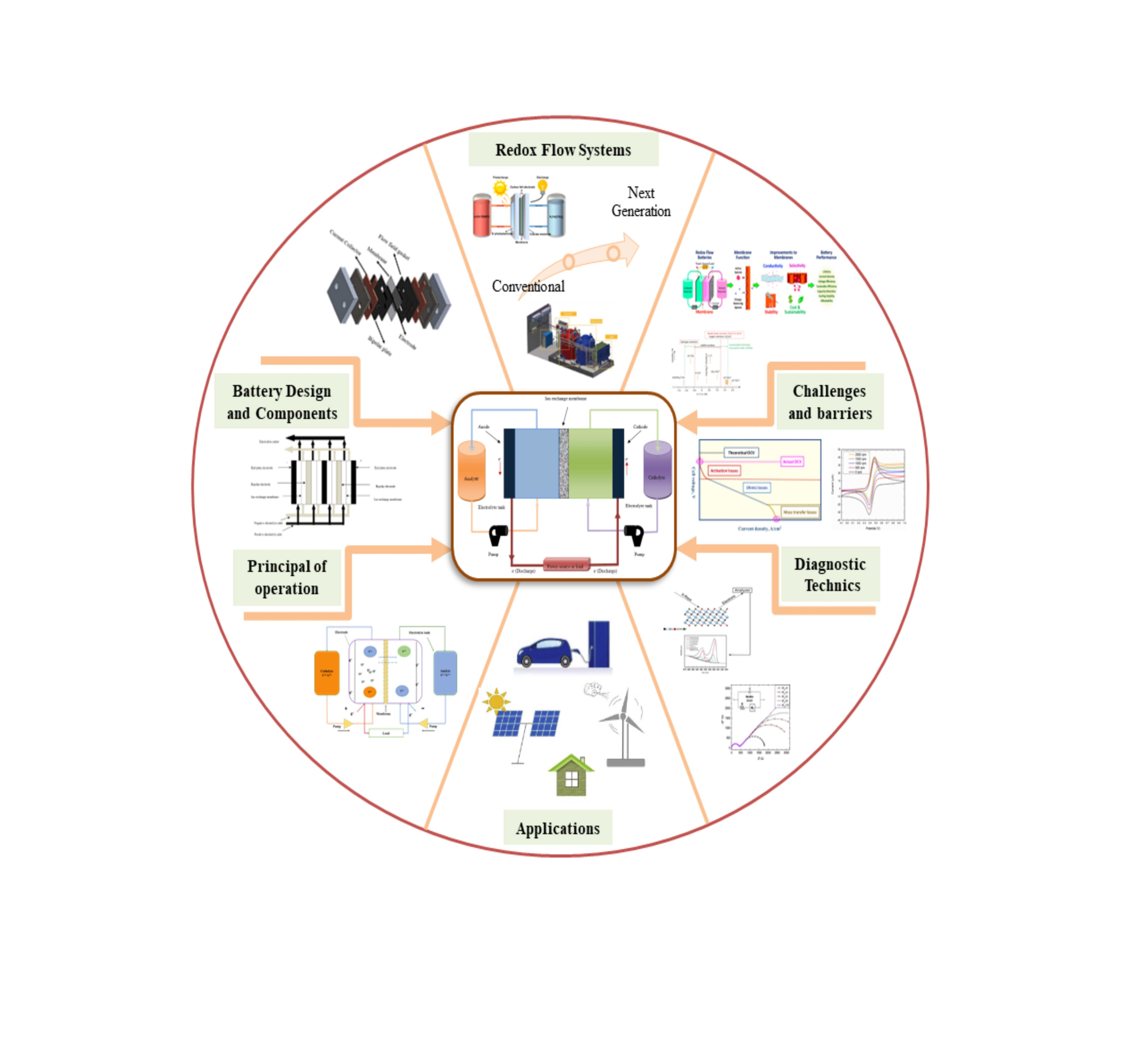
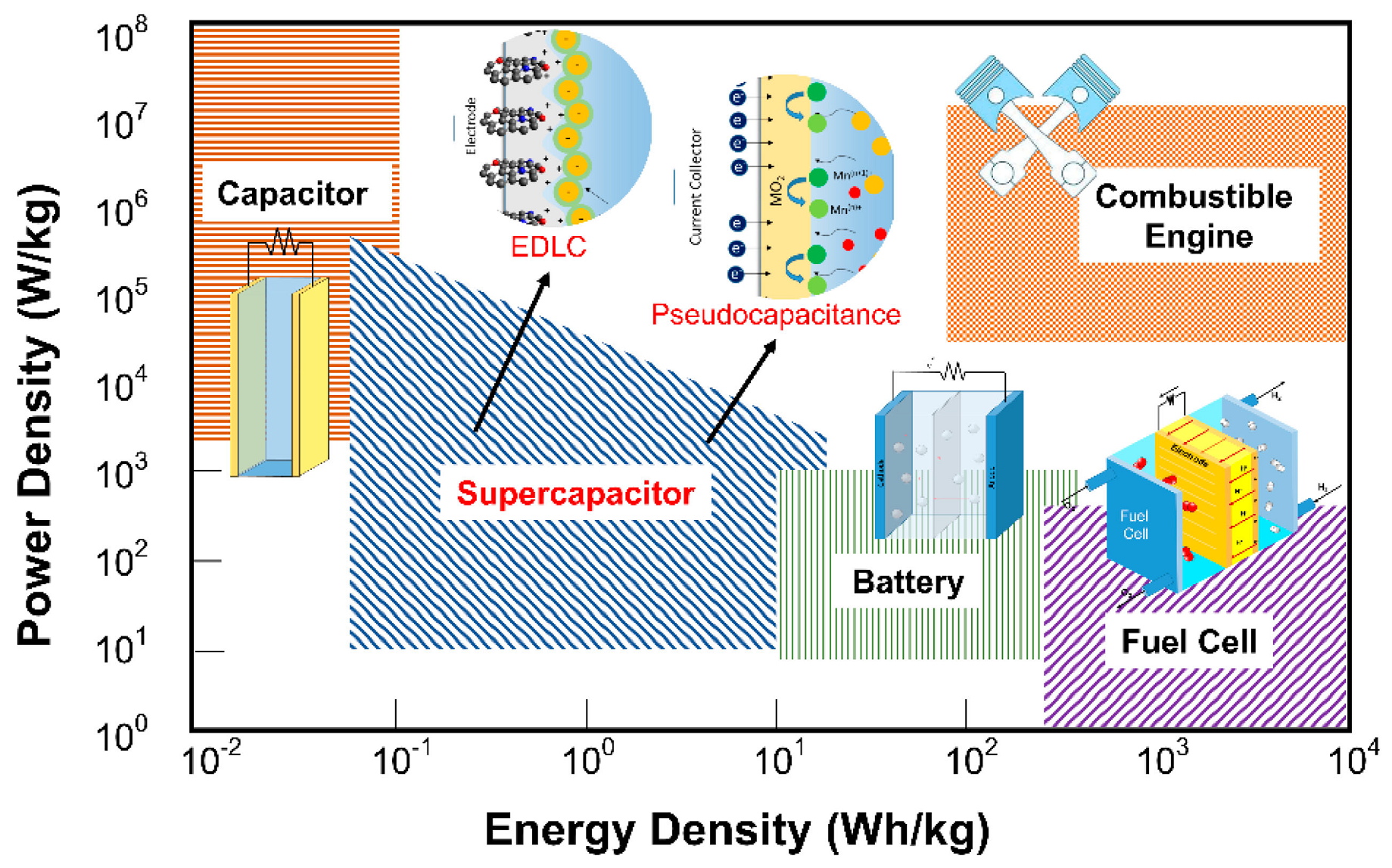
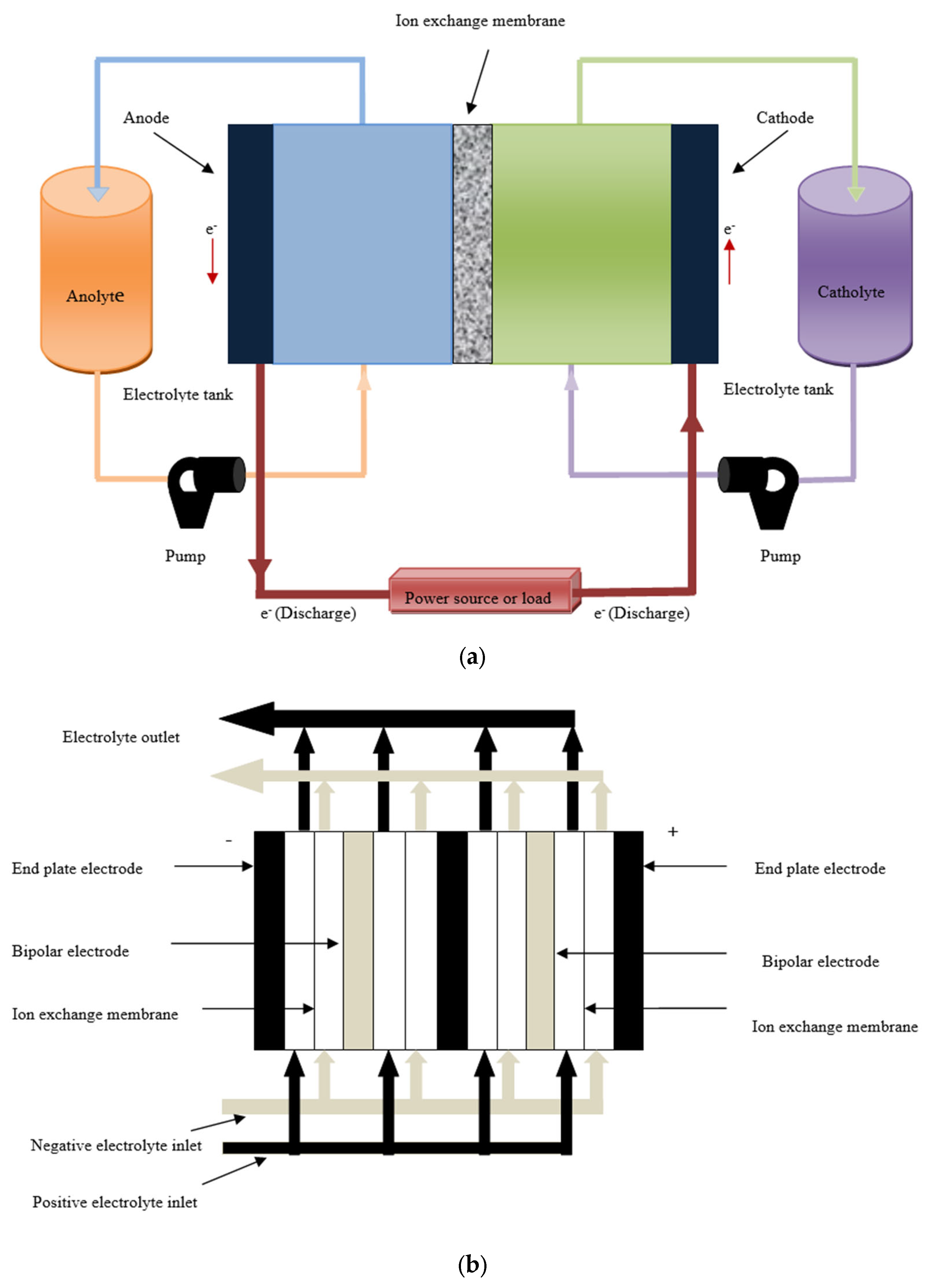
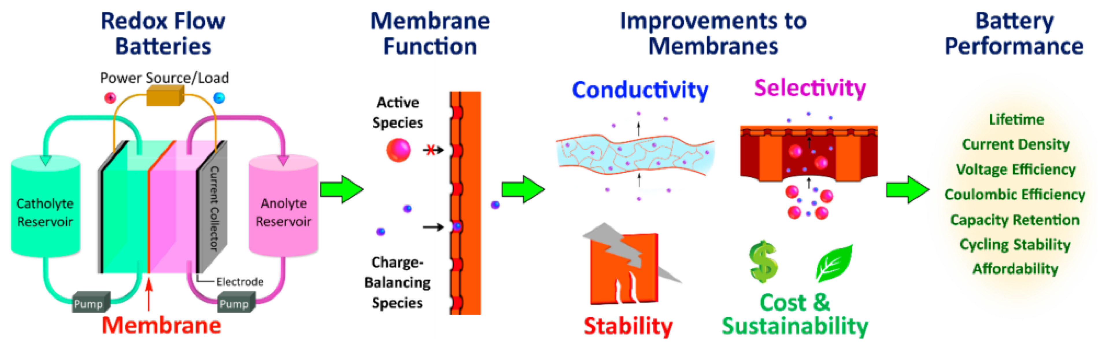
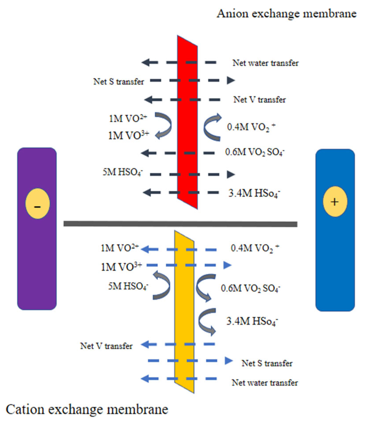
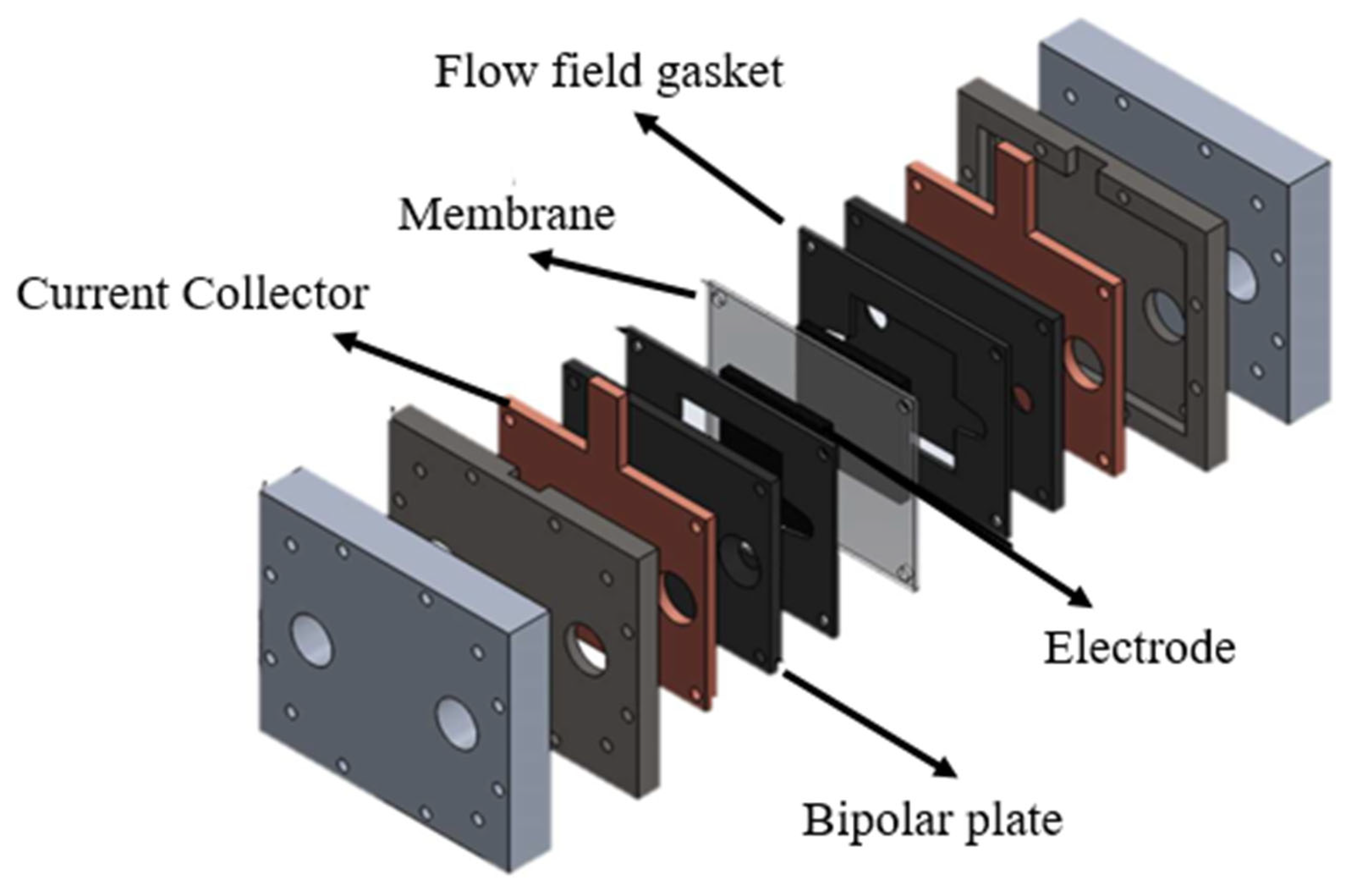
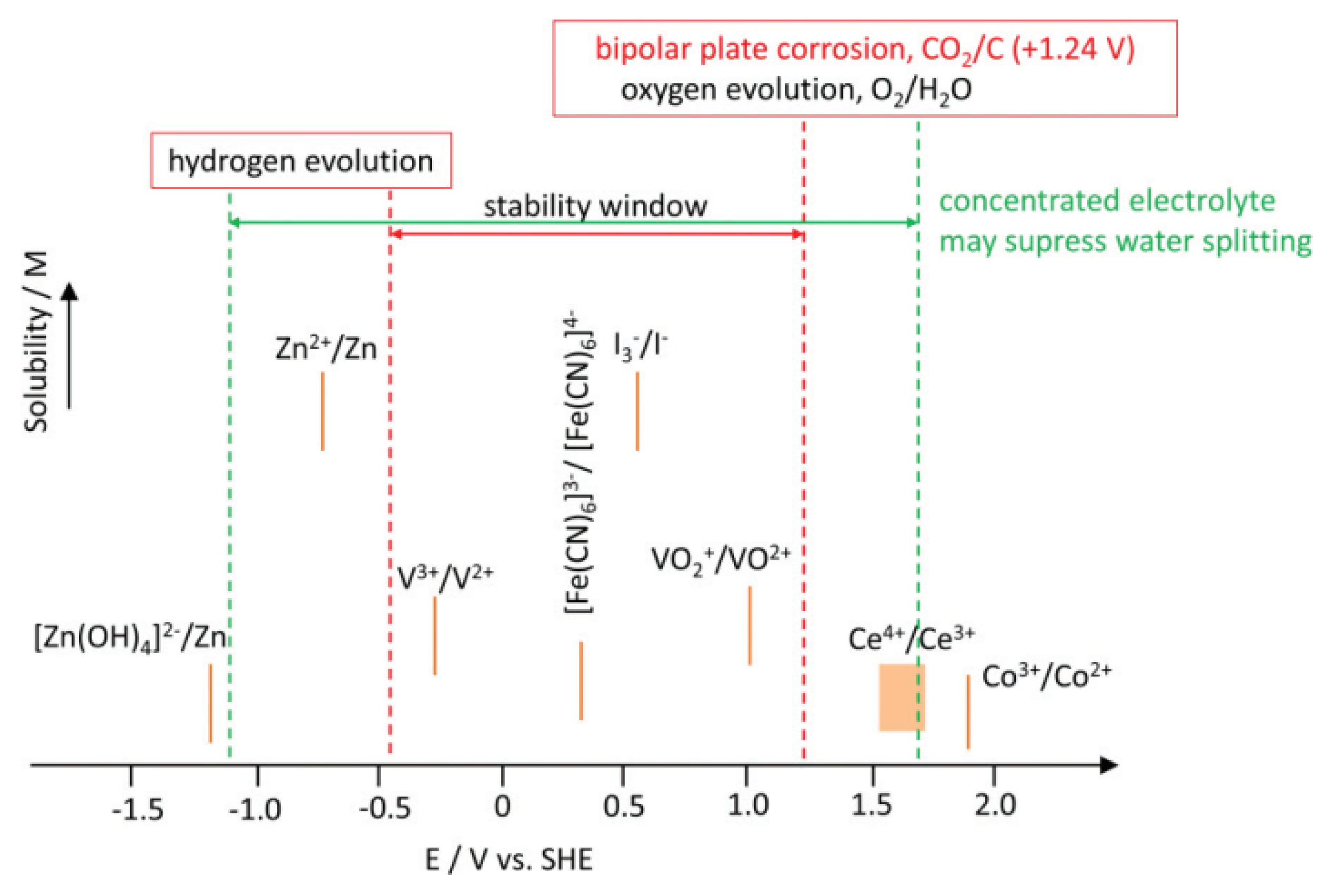
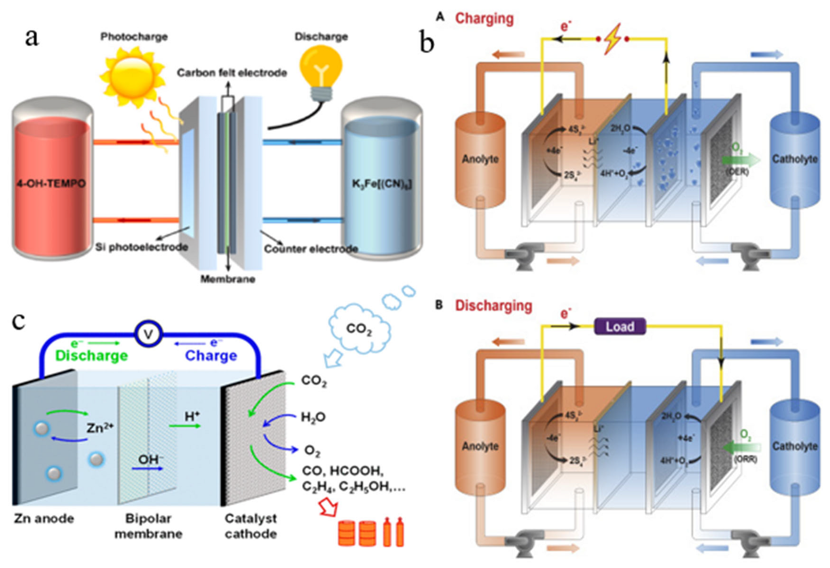
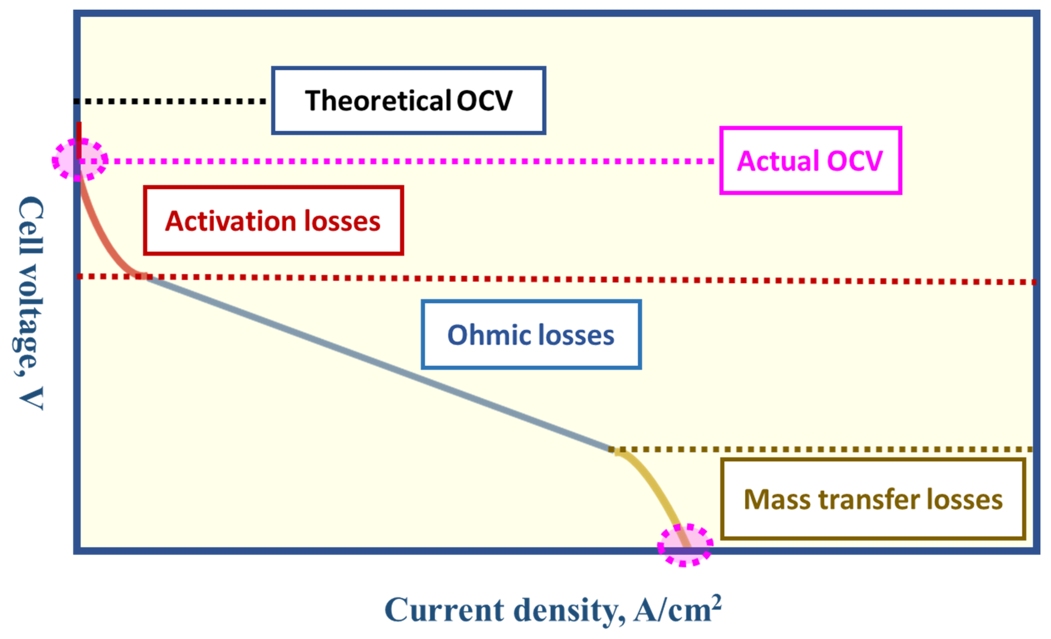
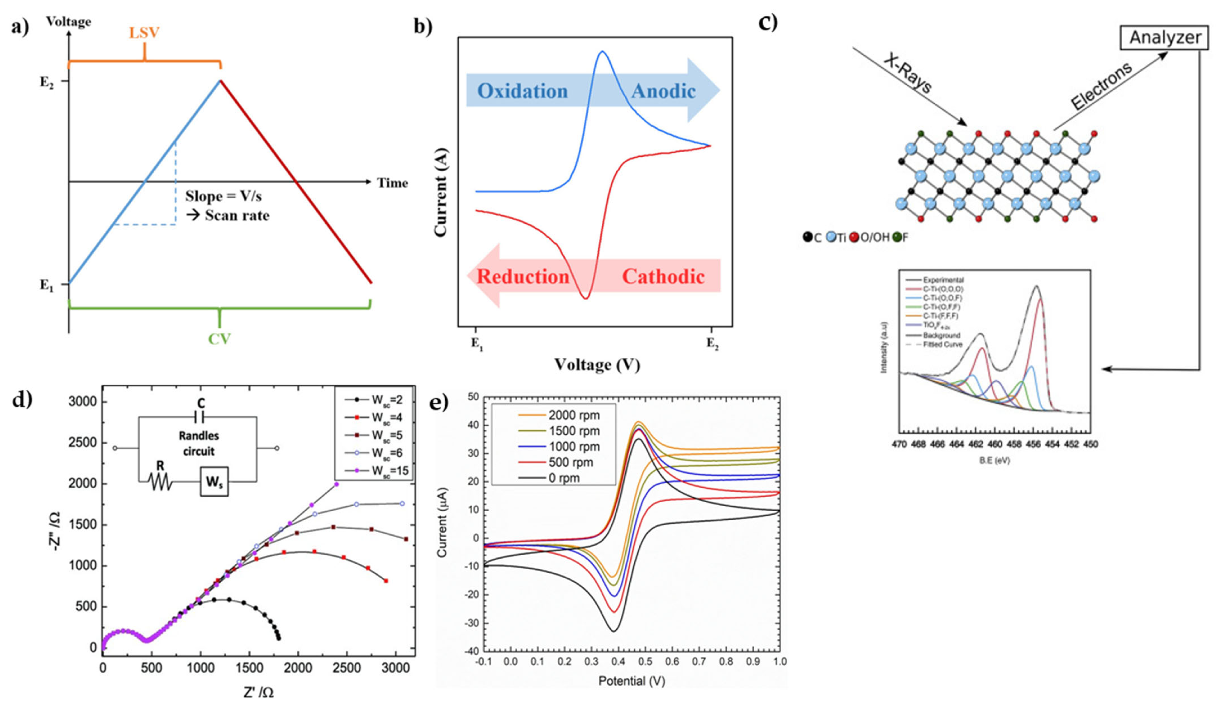
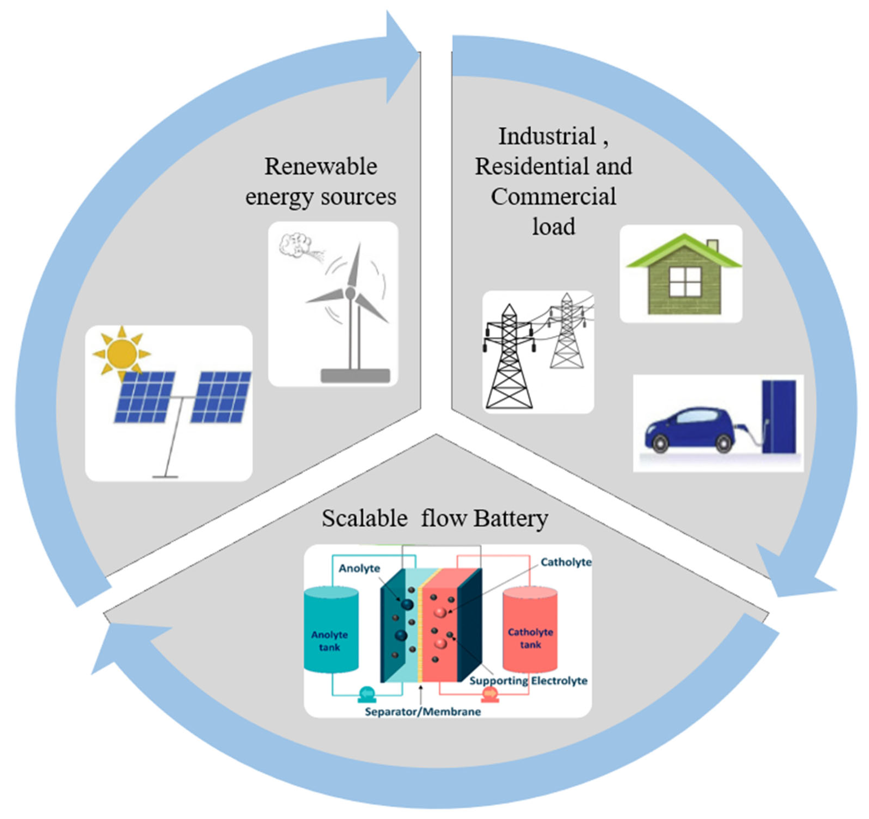
Figure 1. The Ragone plot, comparing various energy storage systems [9,10], open access.
Batteries 09 00409 g001
Figure 2. (a) Schematic of a single cell RFB, depicting electrolyte flowing from storage tanks. The blue side (Bm+/Bm+x), the green side (An/An−x), (b) Stack combined four redox flow cells accompanied by bipolar electrodes.
Batteries 09 00409 g002
Figure 3. Improving RFB membranes, expected to lead to enhanced battery performance. Reprinted with permission from Ref. [62] 2021, American Chemical Society.
Batteries 09 00409 g003
Figure 4. Various fluxes across the cation exchange membrane, and anion exchange membrane, for the vanadium electrolyte solutions.
Batteries 09 00409 g004
Figure 5. Assembling bipolar plates with their corresponding flow channels and membrane-electrode redox flow batteries [160], open access.
Batteries 09 00409 g005
Figure 6. The potentials and relative solubility of various inorganic and organic redox couples for redox flow batteries. The dotted lines indicate the electrochemical stability limit of typical aqueous electrolytes, while the dashed lines represent the potential to extend the stability limit for aqueous electrolytes by using concentrated electrolytes [136], open access.
Batteries 09 00409 g006
Figure 8. General polarization curve for an electrochemical power conversion device with multiple sources of over potential.
Batteries 09 00409 g008
Figure 10. Redox flow battery application on a large scale.
Batteries 09 00409 g010
Table 1. Comparison among different batteries in terms of: Applications, cost, and performance [10,12,14,29,30,31,32,33,34,35,36]. Adapted with permission from Ref. [37], 2021, Elsevier.
TechnologyLife Cycle at 80% Depth of Discharge (DoD)Efficiency (%)Specific Energy (Wh/L)Energy
Density
(W/L)
AdvantagesLimitationsApplicationsCapital Cost
per Unit Energy (USD/kw
h–Output)
Flow battery2000–20,00065–854010–50
-
Nearly unlimited longevity
-
Scalability
High maintenance
-
An extra electrolyte tank is needed
-
Complex monitoring and control
-
Can be used alongside solar and wind for load balancing
-
UPS
-
EV
110–2000
Lead-acid batteries300–300070–9035–4080–90
-
Cheap
-
Available
-
Low-energy density
-
Restricted cycling ability
-
High environmental impact
-
Emergency lighting
-
Electric motors
-
Diesel-electric submarines
350–1500
Ni-Cd batteries30008040–6050–150
-
Good life cycle
-
Improved low-temperature performance
-
High tolerance level
-
High self-discharge rate
-
High environmental impact
-
Memory effect
-
Low-cost rechargeable batteries
-
Battery manufacturing companies
800–3000
Lithium-ion batteries300075–90100–265250–693
-
High energy density
-
Fast response time
-
High efficiency and low self-discharge rate
-
No memory effect
-
High initial expense
-
Safety issue depending on the type
-
Portable devices like mobile phones, laptops, etc.
-
Thermometers, remote car locks, laser pointers, MP3 players, hearing aids, etc.
-
Electric vehicles (EVs)
850–5000
Na-S batteries450089150–30010,000
-
High efficiency
-
High life cycle
-
High maintenance
-
High maintenance
-
High operating temperatures
-
Load balancing
-
Secondary UPS
-
EV
NA
Hydrogen battery (fuel cell)20,00020–66300–300500<
-
Less environmental impact
-
Long life cycle
-
Bulky and heavy
-
high-cost catalyst
-
Energy for producing hydrogen
-
Electrical energy in satellite
-
Space probes
NA
(NA = unavailable).
Table 2. Membrane properties based on ex situ property evaluation score [135], open access.
Membrane Property
Membrane
(Commercial Name)
Mechanical
Property
Vanadium Cross-OverIonic Conductivity
σ (mS·cm−1)
Area
Resistance
(Ω·cm2)
Ion Selectivity
(S·s · cm−3·106)
Swelling Property
Peak Stress Loss (%)Diffusion Coefficients of VO2+ Ions (cm2·s−1·10−7)Dimensional Changes
(Volume Changes) (%)
Mass Changes (%)
N212200.1170 ± 60.471.08 ± 46 ± 0.2
FS-930250.1884 ± 80.540.33 ± 13 ± 1
DF180.09260 ± 10.481.46 ± 34 ± 2
VAN401.620.54 ± 0.011.230.12 ± 1101 ± 6
AMV60.00253.9 ± 0.02.0821.82 ± 29 ± 1
CMV40.0354.6 ± 0.40.625.50 ± 11 ± 1
AHA320.0322.4 ± 0.22.392.87 ± 18 ± 2
FAB-45070.07038 ± 30.591.642 ± 857 ± 3
(Nafion N212, Fumapem FS-930, Dongyue DF, Selemion AMV, Neosepta AHA, Fumapem FAP-450, VANADion™-20 VAN, and Selemion CMV).
Table 3. Electrode materials used in redox flow batteries.
Electrode MaterialThicknessElectrode
Polarity
Flow Battery
System
Refs.
Carbon-Based Electrodes
Carbon felt GFA-type8 mm+veZinc–cerium[175]
Carbon polymer binders: PVA,
PVDF, HDPE
6 mm
(substrate)
−veZinc–cerium[175,176]
Graphite felt NA+ve & −veAll–vanadium[177]
PAN-based graphite felt 5 mm+veBromine
polysulfide
[178]
Cobalt coated PAN-based graphite
felt
5 mm−veBromine
polysulfide
[178]
70 ppi reticulated vitreous carbon1.5 mm+veSoluble lead
acid
[179]
Graphite felt bonded electrode
assembly with nonconducting plastic
substrate
NA+ve & −veAll–vanadium[180]
Porous graphite 2 mm+ve & −veZinc–chlorine[181]
Carbon felt
CH type
2.8 mm+ve & −veZinc–bromine[182]
Cylindrical bed of carbon particles2.5 mm+ve & −veBromine
polysulfide
[148]
Metallic electrodes
Nickel foam2.5 mm−veBromine
polysulfide
[183,184]
Cadmium-plated copperNA−veZinc–nickel and
Zinc–air
[185]
Sintered nickel hydroxideNA−veZinc–nickel[183,186]
40 ppi nickel foam40 ppi nickel foam40 ppi nickel foam40 ppi nickel foam[179]
Three-dimensional platinised
titanium mesh stack (4 meshes, 70 g
Pt m-2 loading, 3.5 μm thick)
4 × 2.5
mm
+veZinc-cerium[175]
(NA = unavailable).
Table 4. Catalysts used for redox couple reactions [136,188].
Electrode ReactionsCatalysts
VO2+ + 2H+ + e ⇄ VO2++ H2OMn3O4/carbon fiber
ZrO2
Bi2O3
Nanorod Nb2O5
Ir-modification of carbon felt.
WO3
PbO2
V3+ + e ⇄ V2+Mn3O4/carbon fiber
ZrO2
Bi2O3
Nanorod Nb2O5
TiC
Cr3+ + e ⇄ Cr2+ Noble catalysts
Ce4+ + e ⇄ Ce3+ Platinized titanium
Cl2 + 2e ⇄ 2Cl RuO2
O2 + 4H+ + 4e ⇄ 2H2OPt/Ir mixed oxide
Table 7. Diagnostic and characterization techniques utilized for the RFBs [59,320,321,322,323,324].
TechniquesFunction
Electrochemical Techniques
Galvanostatic charge–discharge (GCD)Analyzing flow battery performance by applying a constant current during charge and discharge processes
Cyclic voltammetry (CV)Evaluating current response to a linear voltage sweep
Current interrupt (CI)Relating transient voltage response to cell parameters from current interruption events
Electrochemical impedance spectroscopy (EIS)Measuring the impedance of an electrochemical system over a range of frequencies
Rotating disk electrode (RDE)Studying reaction mechanism behavior and mass transport characteristics
Ultraviolet–visible (UV–Vis) spectroscopyQuantitatively measuring the number of ionic species present in the electrolyte
Galvanostatic intermittent titration technique (GITT)Determining the diffusion coefficient by applying short current pulses and analyzing the potential response
Potentiostatic intermittent titration technique (PITT)Determining the diffusion coefficient by applying short potential pulses and analyzing current response
Charge pulse relaxation (CPR)Determining the diffusion coefficient by measuring the relaxation time of a charge pulse
Potential distribution (PD)Examining the potential distribution of half cells and bipolar plates in a multi-cell stack
Nuclear magnetic resonance (NMR) spectroscopyObserving the migration of cations or anions
Electron spin resonance (ESR) spectroscopyStudying rotational diffusion for various materials containing organic free radicals or transition metals
Physical and Spectroscopic
Thermal visualization of flow distributionStudying and visualizing electrolyte flow patterns and distribution in flow battery systems
Optical visualization of flow distributionVisualizing flow patterns and distribution using optical techniques
Scanning electron microscopy (SEM)Characterizing materials on micro- and nanoscale resolutions
Transmission electron microscopy (TEM)Studying the structure and properties of materials at the nanoscale
Energy dispersive X-ray spectroscopy (EDS)Performing elemental analysis
Raman spectroscopyCharacterizing molecular vibrations
Brunauer–Emmett–Teller (BET)Examining the surface area of a material
X-ray diffraction (XRD) analysisStudying the crystallographic structure of materials
Pair distribution function (PDF)Extracting structural information from amorphous or disordered systems
X-ray absorption spectroscopy (XAS)Probing the electronic and atomic structure of materials
X-ray photoelectron spectroscopy (XPS)Analyzing surface composition and chemical states
X-ray tomographic microscopy (XTM)Visualizing the 3D microstructure of samples
X-ray fluorescence spectroscopy (XRF)Determining the elemental composition of a sample
Fourier transform infrared spectroscopy (FTIR)Identifying molecular bonds and structures
Atomic force microscopy (AFM)Imaging surfaces at the atomic and molecular scale
Secondary ion mass spectrometry (SIMS)Analyzing surface composition and depth profiling of materials
Disclaimer/Publisher’s Note: The statements, opinions and data contained in all publications are solely those of the individual author(s) and contributor(s) and not of MDPI and/or the editor(s). MDPI and/or the editor(s) disclaim responsibility for any injury to people or property resulting from any ideas, methods, instructions or products referred to in the content.

