
Hybrid Energy Storage Systems Based on Redox-Flow Batteries: Recent Developments, Challenges, and Future Perspectives
 , ,
, ,
Abstract
:1. Introduction
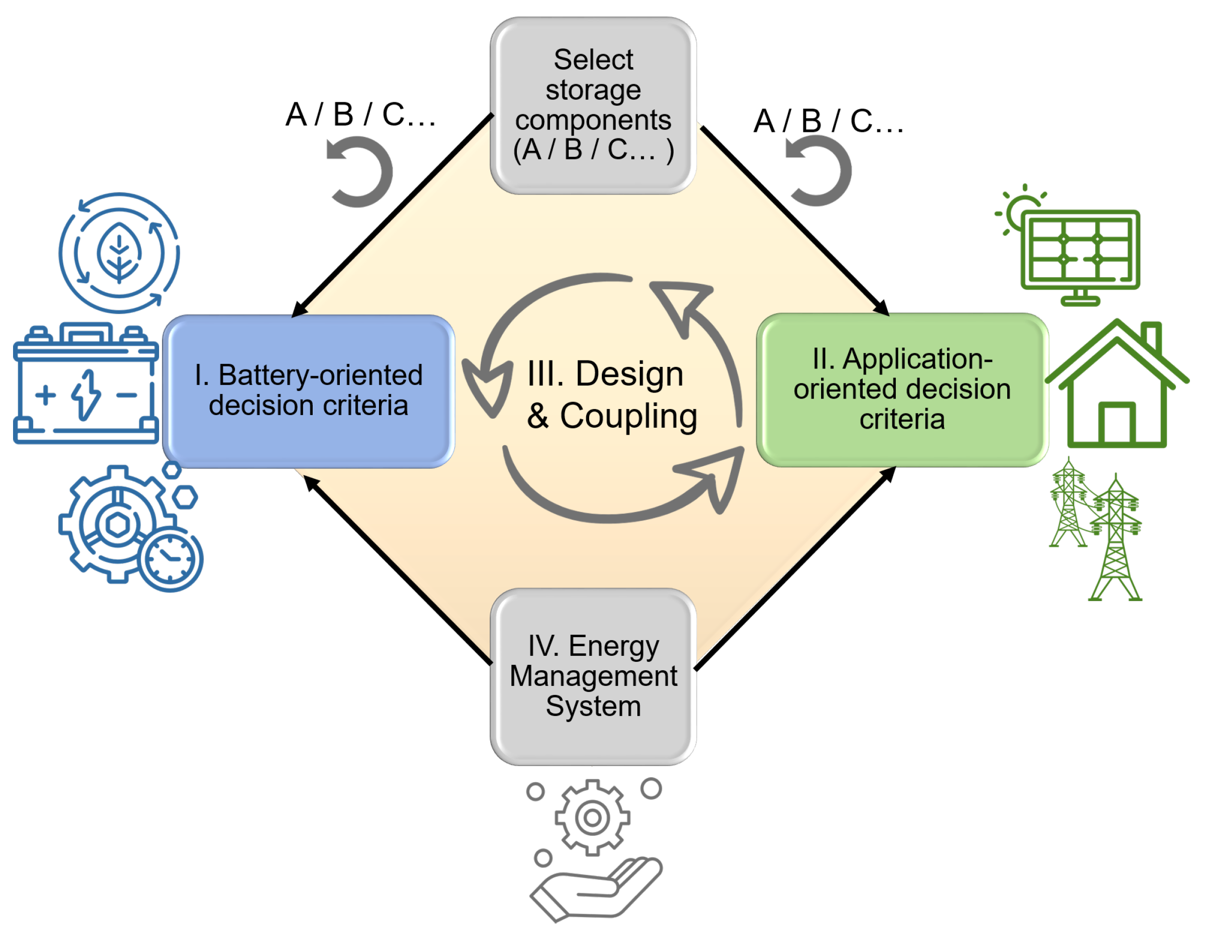
2. Evaluation of Key Performance Indicators
2.1. Classification of Single Storage Components
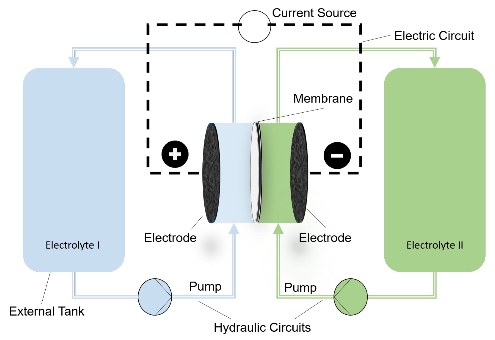
2.1.1. Redox-Flow Batteries (RFBs)
2.1.2. Lithium-Ion Batteries (LIBs)
2.1.3. Sodium–Sulfur Batteries (NaSs)
2.1.4. Lead–Acid Batteries (PbAs)
2.1.5. Supercapacitors (SCs)
2.1.6. Superconducting Magnetic Energy Storage (SMES)
2.1.7. Evaluation of Key Performance Indicators
2.2. Classification of HESSs
2.2.1. Definition of a HESS
- 1.
- Primarily ESS cluster: has to satisfy the requirements of higher peak power demand and has to handle the fast transient fluctuations, e.g., load or Renewable Energy Sources (RES) production. This cluster is marked by fast response time, high power peaks, high efficiency, and high cycle lifetime.
- 2.
- Secondary ESS cluster: has to comply with the requirement of high storage duration. This cluster is characterized by a low self-discharge rate and high efficiency.
2.2.2. Evaluation of Key Performance Indicators
3. Coupling Architecture Optimization Strategy
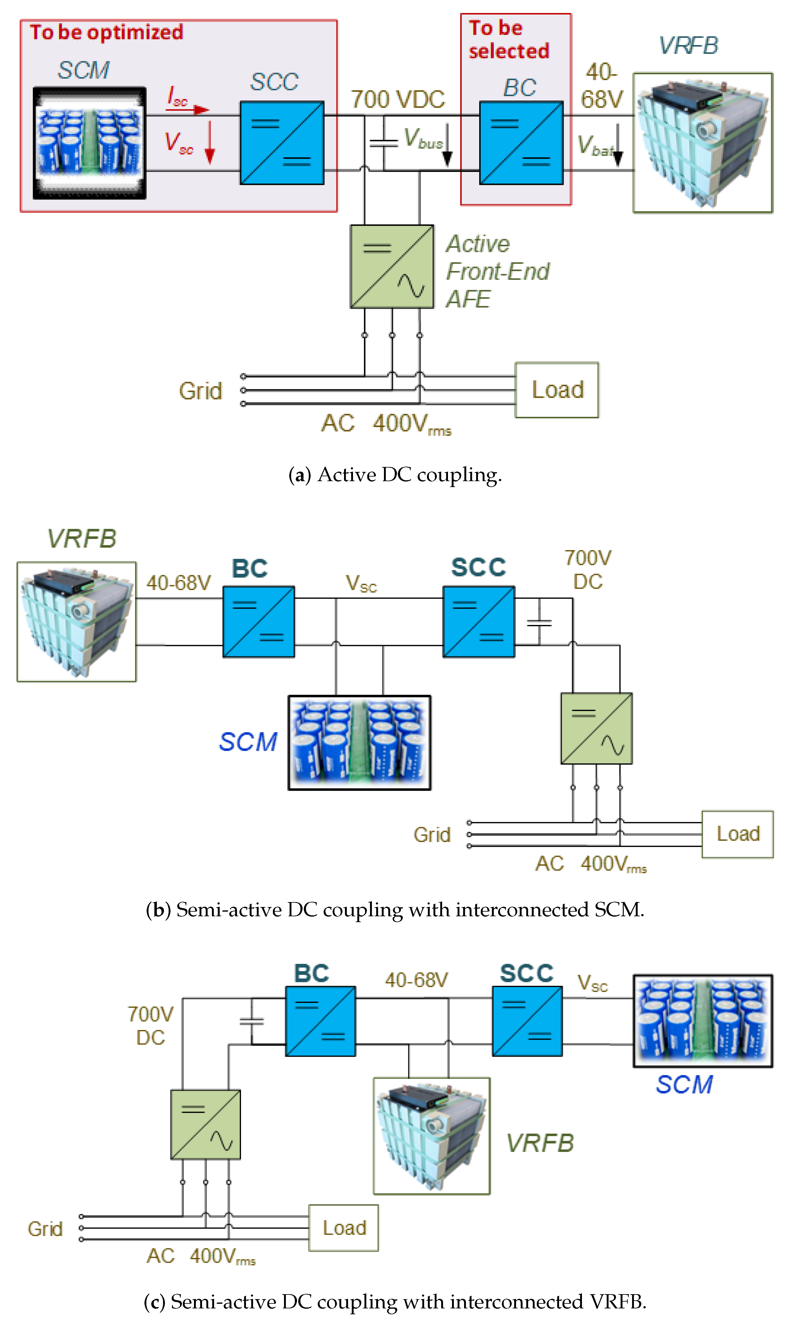
3.1. Coupling Architectures of Hybrid Storage Systems
3.2. HESS Optimization Strategy
4. Energy Management System (EMS) for HESS
4.1. Energy Management Structure for HESS
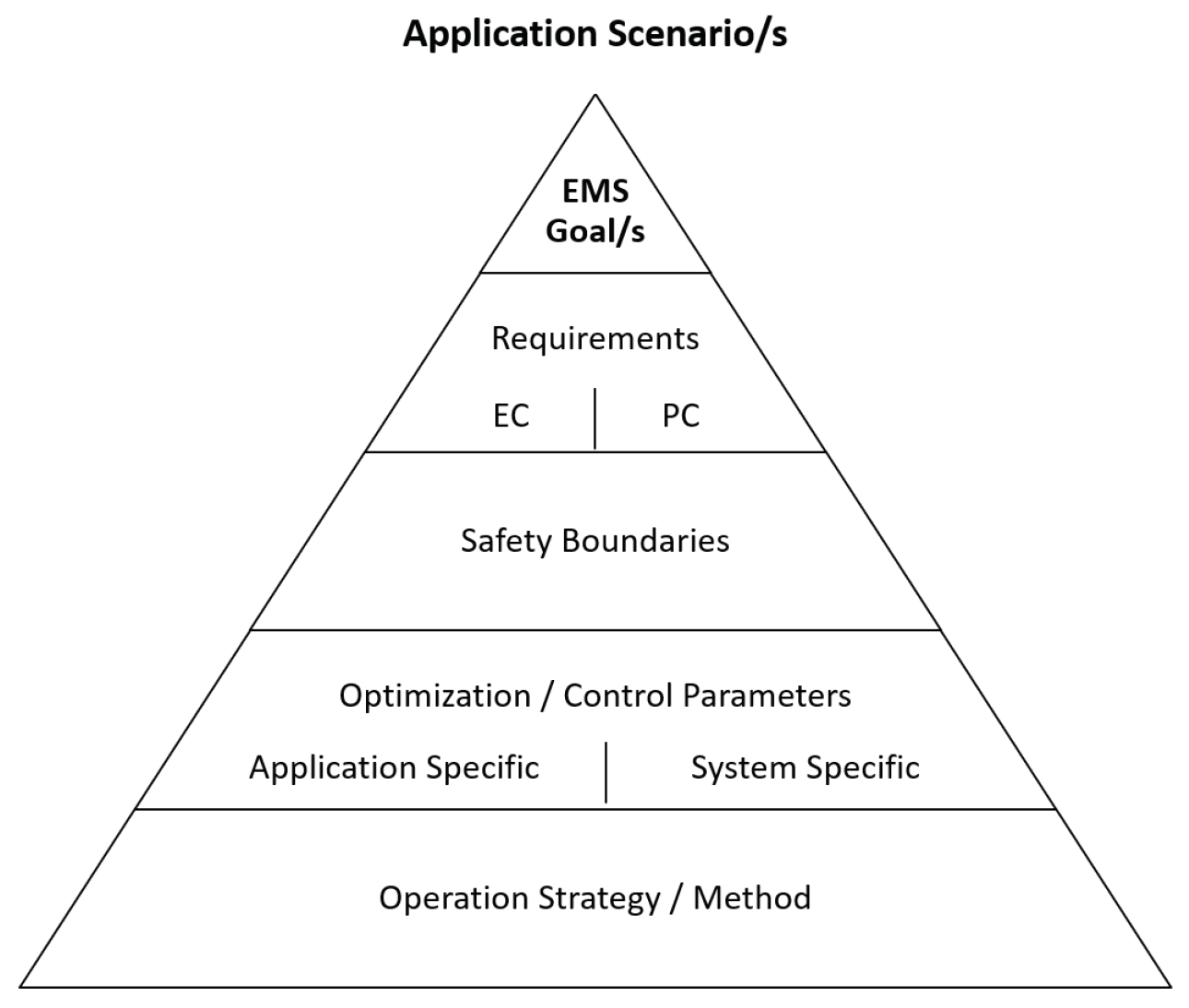
4.1.1. Application Scenarios
- 1.
- Transmission grid (T);
- 2.
- Distribution grid (D);
- 3.
- Behind the meter at end-user locations (E-U).

| Source | Application | Purpose | Placement | Control | Duration | Control Parameter | Controller Rate |
|---|---|---|---|---|---|---|---|
| [38,46,47,48,49,50] | Momentary Reserve | S | T | P | t < msec | f_AC 1 | <20 ms |
| [1,38,43,46,47,49,50,53,54] | Primary Control | S/G | T | P | t < msec | P_AC f_AC 1 | <30 s |
| [10,38,42] | Secondary Control | S/G | T | P | s < t > 15 min | P_AC f_AC 1 | <5 min |
| [10,38,42] | Tertiary Control | S/G | T | P | min < t > 60 min | P_AC f_AC 1 | <15 min |
| [10,38,42] | Black Start | S | - | P | s <t > min | P 3 f_AC 1 U_AC | 1–10 s |
| [1,10,38,42,44,55] | Island Grid 4 | S | - | E | s < t > days | P 3 | 1 s–1 min |
| [1,38,42] | Transmission Support and Stability | S | T | E | t > h | P 3 | 1 s–1 min |
| [10,38,42,49,56,57] | Voltage Support | G /S | T/D | P | 15 min < t >h | U 2 | 1–15 min |
| [1,10,38,42,43,46,49,50,52] | Distribution Power Quality | G /S | D | P | s < t > min | P 3 | 1 s–1 min |
| [10,38,43,44,52] | Peak Shaving (all time scales) | M /G | E-U | P | s < t > 15 min | P 3 | 30 s–1 min |
| [38] | Uninterruptible Power Supply | M | E-U | P/E | s < t > h | P f_AC U | <20 ms |
| [38,46,47,49,50,52,56,57] | Energy Time Shifting | M | E-U | E | 15 min < t > days | P 3 t | 1–15 min |
| [1,38,43] | Energy Trading, Arbitrage | M | - | E | 15 min < t > h | P 3 EUR/kW EUR/kWh | 1–15 min |
4.1.2. Control and Optimization Parameters
4.2. Energy Management Optimization for HESS
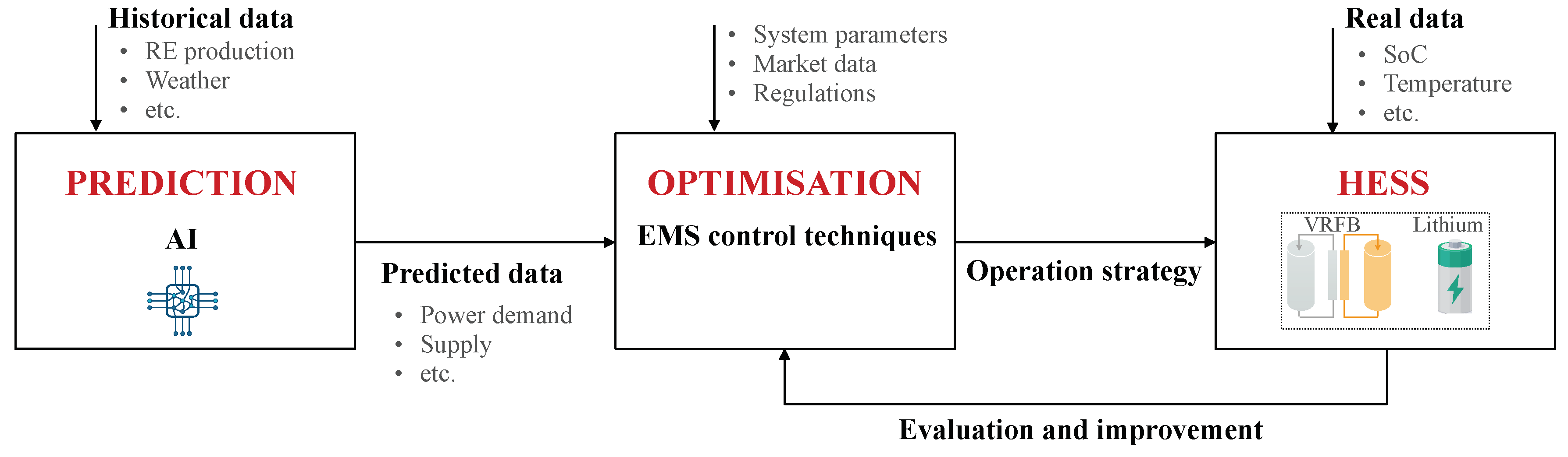
4.2.1. Prediction
4.2.2. EMS Control Techniques
- 1.
- Low-level optimization functions control the AC/DC bus voltage and the electric current flow.
- 2.
- High-level optimization functions control many energy management strategies, among which are power performance, SoC monitoring, ESS charge/discharge cycles, and energy cost reduction.
- 1.
- Classical control techniques mainly include filtration-based control, dead beat control, droop control, and sliding mode control. These techniques are the most used in the literature, as demonstrated in Table 7, and are mainly applied for offline implementation independently of the filtration-based control technique.
- 2.
- Intelligent control techniques are classified into rule-based techniques and optimization-based techniques. Rule-based techniques are among the most widely adopted in previous work due to their simplicity in implementation (see Table 7). However, these techniques are still far from perfect, as they require deep knowledge of the domain and the definition of rules for a complex system is a challenging task. Recently, there has been considerable interest in real-time optimization techniques, with a rapid rise in the use of Deep Learning (DL) and Machine Learning (ML) algorithms, e.g., Neural Network (NN) and Reinforcement Learning (RL). ML techniques deliver accurate results in real time, but on the other hand, they require a lot of training data and suffer from high computational complexity.
5. Related Work
6. Conclusions
- The advance of real-time optimization of EMS came at a very high computational cost. One solution to address this issue is the use of the Digital Twin (DT) concept. DT uses real-world data to create a simulation that predicts system future performance [100]. DT has been recently adopted in many application fields due to several advantages, in particular energy management and operation optimization improvement.
Author Contributions
Funding
Data Availability Statement
Conflicts of Interest
Abbreviations
| AC | Alternating Current |
| AFE | Active Front End |
| ANN | Artificial Neural Network |
| AORFB | Aqueous Organic Redox-Flow Battery |
| ARIMA | Auto Regressive Integrated Moving Average |
| BC | Battery Converter |
| BMS | Battery Management System |
| CNN | Convolution Neural Networks |
| D | Distribution Grid |
| DC | Direct Current |
| DT | Digital Twin |
| E | Energy |
| EC | Energy Component |
| EES | Electrical Energy Storage |
| EMS | Energy Management System |
| ESS | Energy Storage System |
| E-U | Behind the Meter at End-User Locations |
| FC | Fuel Cell |
| GA | Gradient Descent |
| GAN | Generative Adversarial Network |
| HESS | Hybrid Energy Storage System |
| ISC | Supercapacitor Current |
| Isol | Isolated |
| G | Grid |
| KPI | Key Performance Indicator |
| LIB | Lithium-Ion Battery |
| LSTM | Long Short Term Memory |
| M | Manage |
| MAE | Mean Absolute Error |
| MAPE | Mean Absolute Percentage Error |
| MDPI | Multidisciplinary Digital Publishing Institute |
| MILP | Mixed Integer Linear Programming |
| MINLP | Mixed Integer Nonlinear Programming |
| MLP | Mixed Linear Programming |
| MPC | Model Predictive Control |
| NaS | Sodium–Sulfur Battery |
| NCM | Lithium–Nickel–Cobalt–Manganese Oxide |
| NN | Neural Network |
| Non Isol | Not Isolated |
| NRMSE | Normalized Root-Mean-Square Error |
| N/S | Not Specified |
| OMEI | Open Mobility Electric Infrastructure |
| P | Power |
| PbA | Lead–Acid Battery |
| PC | Power Component |
| PSO | Particle Swarm Optimization |
| RE | Renewable Energy |
| RES | Renewable Energy Sources |
| RFB | Redox-Flow Battery |
| RL | Reinforcement Learning |
| RMSE | Root-Mean-Square Error |
| RNN | Recurrent Neural Networks |
| S | System |
| SC | Supercapacitor |
| SCC | Supercapacitor Converter |
| SCM | Supercapacitor Module |
| SoC | State of Charge |
| SMES | Superconducting Magnetic Energy Storage |
| T | Transmission Grid |
| UPS | Uninterruptible Power Supply |
| VRFB | Vanadium Redox-Flow Battery |
| VSC | Voltage at Supercapacitor Module |
References
- U.S. Department of Energy. Energy Storage Grand Challenge Energy Storage Market Report; National Renewable Energy Lab. (NREL): Golden, CO, USA, 2020.
- Maria, S.K.; Miron, R.; Robert, R. All-Vanadium Redox Battery. U.S. Patent US4786567A, 2 November 1986. [Google Scholar]
- Kurzweil, P.; Dietlmeier, O. Elektrochemische Speicher: Superkondensatoren, Batterien, Elektrolyse-Wasserstoff, Rechtliche Grundlagen, Wiesbaden; Springer: Berlin/Heidelberg, Germany, 2015. [Google Scholar] [CrossRef]
- Deepika, D.; Singh, N. Exponential state observer based finite time control of fully active hybrid energy storage system. Sādhanā 2022, 47, 21. [Google Scholar] [CrossRef]
- Hu, W.; Shang, Q.; Bian, X.; Zhu, R. Energy management strategy of hybrid energy storage system based on fuzzy control for ships. Int. J. Low-Carbon Technol. 2022, 17, 169–175. [Google Scholar] [CrossRef]
- Jing, W.; Hung Lai, C.; Wong, S.H.W.; Wong, M.L.D. Battery-supercapacitor hybrid energy storage system in standalone DC microgrids: Areview. IET Renew. Power Gener. 2017, 11, 461–469. [Google Scholar] [CrossRef]
- Babu, T.S.; Vasudevan, K.R.; Ramachandaramurthy, V.K.; Sani, S.B.; Chemud, S.; Lajim, R.M. A Comprehensive Review of Hybrid Energy Storage Systems: Converter Topologies, Control Strategies and Future Prospects. IEEE Access 2020, 8, 148702–148721. [Google Scholar] [CrossRef]
- Ali, M.H.; Slaifstein, D.; Ibanez, F.M.; Zugschwert, C.; Pugach, M. Power Management Strategies for Vanadium Redox Flow Battery and Supercapacitors in Hybrid Energy Storage Systems. In Proceedings of the 2022 IEEE PES Innovative Smart Grid Technologies Conference Europe (ISGT-Europe), Novi Sad, Serbia, 10–12 October 2022; IEEE: Piscataway, NJ, USA, 2022; pp. 1–5. [Google Scholar]
- Behera, M.K.; Saikia, L.C. A Novel Resilient Control of Grid-Integrated Solar PV-Hybrid Energy Storage Microgrid for Power Smoothing and Pulse Power Load Accommodation. IEEE Trans. Power Electron. 2022, 38, 3965–3980. [Google Scholar] [CrossRef]
- Das, C.K.; Bass, O.; Kothapalli, G.; Mahmoud, T.S.; Habibi, D. Overview of energy storage systems in distribution networks: Placement, sizing, operation, and power quality. Renew. Sustain. Energy Rev. 2018, 91, 1205–1230. [Google Scholar] [CrossRef]
- Dehghani-Sanij, A.R.; Tharumalingam, E.; Dusseault, M.B.; Fraser, R. Study of energy storage systems and environmental challenges of batteries. Renew. Sustain. Energy Rev. 2019, 104, 192–208. [Google Scholar] [CrossRef]
- Ferreira, H.L.; Garde, R.; Fulli, G.; Kling, W.; Lopes, J.P. Characterisation of electrical energy storage technologies. Energy 2013, 53, 288–298. [Google Scholar] [CrossRef]
- Kangro, W. Verfahren zur Speicherung von Elektrischer Energie. German Patent DE914264C, 28 June 1949. [Google Scholar]
- Kangro, W. Verfahren zur Speicherung von elektrischer Energie in Fluessigkeiten. German Patent DE1006479B, 14 July 1954. [Google Scholar]
- Thaller, L.H. Electrically rechargeable REDOX Flow Cell. U.S. Patent US3996064A, 22 August 1975. [Google Scholar]
- Sterner, M.; Stadler, I. Energiespeicher: Bedarf, Technologien, Integration; Springer: Berlin/Heidelberg, Germany, 2014. [Google Scholar] [CrossRef]
- Weber, A.Z.; Mench, M.M.; Meyers, J.P.; Ross, P.N.; Gostick, J.T.; Liu, Q. Redox flow batteries: A review. J. Appl. Electrochem. 2011, 41, 1137–1164. [Google Scholar] [CrossRef]
- Skyllas-Kazacos, M.; Chakrabarti, M.H.; Hajimolana, S.A.; Mjalli, F.S.; Saleem, M. Progress in Flow Battery Research and Development. J. Electrochem. Soc. 2011, 158, R55. [Google Scholar] [CrossRef]
- Choi, C.; Kim, S.; Kim, R.; Choi, Y.; Kim, S.; Jung, H.y.; Yang, J.H.; Kim, H.T. A review of vanadium electrolytes for vanadium redox flow batteries. Renew. Sustain. Energy Rev. 2017, 69, 263–274. [Google Scholar] [CrossRef]
- Sánchez-Díez, E.; Ventosa, E.; Guarnieri, M.; Trovò, A.; Flox, C.; Marcilla, R.; Soavi, F.; Mazur, P.; Aranzabe, E.; Ferret, R. Redox flow batteries: Status and perspective towards sustainable stationary energy storage. J. Power Sources 2021, 481, 228804. [Google Scholar] [CrossRef]
- Noack, J.; Roznyatovskaya, N.; Herr, T.; Fischer, P. The Chemistry of Redox-Flow Batteries. Angew. Chem. 2015, 54, 9776–9809. [Google Scholar] [CrossRef] [PubMed]
- Luo, X.; Wang, J.; Dooner, M.; Clarke, J. Overview of current development in electrical energy storage technologies and the application potential in power system operation. Appl. Energy 2015, 137, 511–536. [Google Scholar] [CrossRef]
- Soloveichik, G.L. Flow Batteries: Current Status and Trends. Chem. Rev. 2015, 115, 11533–11558. [Google Scholar] [CrossRef] [PubMed]
- Changkun, Z.; Leyuan, Z.; Yu, D.; Sangshan, P.; Xuelin, G.; Yu, Z.; Gaohong, H.; Guihua, Y. Progress and prospects of next-generation redox flow batteries. Energy Storage Mater. 2018, 15, 324–350. [Google Scholar] [CrossRef]
- Goodenough, J. How we made the Li-ion rechargeable battery. Nat. Electron. 2018. [Google Scholar] [CrossRef]
- Welter, K. Die Lithium-Ionen-Batterie: Eine Erfindung Voller Energie; Chemie in unserer Zeit; Wiley Online Library: Hoboken, NJ, USA, 2019. [Google Scholar] [CrossRef]
- Korthauer, R. (Ed.) Handbuch Lithium-Ionen-Batterien; Springer: Berlin/Heidelberg, Germany, 2013. [Google Scholar] [CrossRef]
- Jossen, A.; Weydanz, W. Moderne Akkumulatoren Richtig Einsetzen. 2006. Available online: https://cuvillier.de/uploads/preview/public_file/11447/9783736999459_Inhaltsverzeichnis.pdf (accessed on 10 March 2023).
- Kebede, A.A.; Kalogiannis, T.; van Mierlo, J.; Berecibar, M. A comprehensive review of stationary energy storage devices for large scale renewable energy sources grid integration. Renew. Sustain. Energy Rev. 2022, 159, 112213. [Google Scholar] [CrossRef]
- Chen, H.; Cong, T.N.; Yang, W.; Tan, C.; Li, Y.; Ding, Y. Progress in electrical energy storage system: A critical review. Prog. Nat. Sci. 2009, 19, 291–312. [Google Scholar] [CrossRef]
- Aneke, M.; Wang, M. Energy storage technologies and real life applications—A state of the art review. Appl. Energy 2016, 179, 350–377. [Google Scholar] [CrossRef]
- Koohi-Fayegh, S.; Rosen, M.A. A review of energy storage types, applications and recent developments. J. Energy Storage 2020, 27, 101047. [Google Scholar] [CrossRef]
- Electric Power Research Institute. Electric Energy Storage Technology Options: A White Paper Primer on Applications, Costs, and Benefits; Electric Power Research Institute: Palo Alto, CA, USA, 2010. [Google Scholar]
- Bocklisch, T. Hybrid energy storage systems for renewable energy applications. Energy Procedia 2015, 73, 103–111. [Google Scholar] [CrossRef]
- Fiedler, T.; Mircea, P.M. Energy management systems according to the ISO 50001 standard—Challenges and benefits. In Proceedings of the 2012 International Conference on Applied and Theoretical Electricity (ICATE), Craiova, Romania, 25–27 October 2012; pp. 1–4. [Google Scholar] [CrossRef]
- Barckhausen, A.; Becker, J.; Malodobry, P. 2019. Available online: https://www.adelphi.de/de/publikation/energiemanagementsysteme-der-praxis-0 (accessed on 1 February 2023).
- Li, X.; Wang, S. Energy management and operational control methods for grid battery energy storage systems. CSEE J. Power Energy Syst. 2021, 7, 1026–1040. [Google Scholar] [CrossRef]
- Thielmann, A.; Sauer, A.; Schnell, M.; Isenmann, R.; Wietschel, M. Technologie-Roadmap Stationäre Energiespeicher 2030; Fraunhofer: Munich, Germany, 2015. [Google Scholar]
- Buescher, J.; Hussy, C.; Kessels, K.; Koper, M.; Munzel, B. Support to R&D Strategy for Battery Based Energy Storage: 10 Year R&I Roadmap 2017–2026 (D10); European Network of Transmission System Operators for Electricity: Brussels, Belgium, 2016. [Google Scholar]
- Edström, K.; Dominko, R.; Fichtner, M.; Perraud, S. Battery 2030+ Roadmap; European Commission: Brussels, Belgium, 2020. [Google Scholar] [CrossRef]
- Mongrid, K.; Viswanathan, V.; Alam, J.; Vartanian, C.; Sprenkle, V.; Pacific Northwest National Lboratory; Baxter, R.; Mustang Prairie Energy. 2020 Grid Energy Storage Technology Cost and Performance Assessment; Technical Report; U.S. Department of Energy: Washington, DC, USA, 2020.
- Zander, W.; Lemkens, S.; Macharey, U.; Langrock, T.; Nailis, D.; Zdrallek, M.; Schaefer, K.F.; Steffens, P.; Kornrumpf, T.; Hummel, K.; et al. Optimierter Einsatz von Speichern für Netz-und Marktanwendungen in der Stromversorgung: Teil 1: Ergebniszusammenfassung der Projektsteuergruppe; dena-NETZFLEXSTUDIE: Berlin, Germany, 2017. [Google Scholar]
- Saboori, H.; Hemmati, R.; Ghiasi, S.M.S.; Dehghan, S. Energy storage planning in electric power distribution networks—A state-of-the-art review. Renew. Sustain. Energy Rev. 2017, 79, 1108–1121. [Google Scholar] [CrossRef]
- Kousksou, T.; Bruel, P.; Jamil, A.; El Rhafiki, T.; Zeraouli, Y. Energy storage: Applications and challenges. Sol. Energy Mater. Sol. Cells 2014, 120, 59–80. [Google Scholar] [CrossRef]
- Agricola, A.C.; Seidl, H.; Mischinger, S.; Rehtanz, C.; Greve, M.; Häger, U.; Hilbrich, D.; Kippelt, S.; Kubis, A.; Liebenau, V.; et al. dena-Studie Systemdienstleistungen 2030. In Voraussetzungen für eine sichere und zuverlässige Stromversorgung mit Hohem Anteil Erneuerbarer Energien; Endbericht; dena-NETZFLEXSTUDIE: Berlin, Germany, 2014. [Google Scholar]
- Krishan, O.; Suhag, S. An updated review of energy storage systems: Classification and applications in distributed generation power systems incorporating renewable energy resources. Int. J. Energy Res. 2019, 43, 6171–6210. [Google Scholar] [CrossRef]
- U.S. Energy Information Administration. Battery Storage in the United States: An Update on Market Trends; U.S. Energy Information Administration: Washington, DC, USA, 2020.
- Kennedy, R. Battery Storage Capacity More than Tripled in 2021. 2022. Available online: https://pv-magazine-usa.com/2022/07/07/battery-storage-capacity-more-than-tripled-in-2021/ (accessed on 1 February 2023).
- Ribeiro, P.F.; Johnson, B.K.; Crow, M.L.; Arsoy, A.; Liu, Y. Energy storage systems for advanced power applications. Proc. IEEE 2001, 89, 1744–1756. [Google Scholar] [CrossRef]
- Palizban, O.; Kauhaniemi, K. Energy storage systems in modern grids—Matrix of technologies and applications. J. Energy Storage 2016, 6, 248–259. [Google Scholar] [CrossRef]
- Qu, D.; Wang, G.; Kafle, J.; Harris, J.; Crain, L.; Jin, Z.; Zheng, D. Electrochemical Impedance and its Applications in Energy-Storage Systems. Small Methods 2018, 2, 1700342. [Google Scholar] [CrossRef]
- Leung, P.; Li, X.; Ponce de León, C.; Berlouis, L.; Low, C.T.J.; Walsh, F.C. Progress in redox flow batteries, remaining challenges and their applications in energy storage. Rsc Adv. 2012, 2, 10125. [Google Scholar] [CrossRef]
- Schulz, D. (Ed.) Nachhaltige Energieversorgung und Integration von Speichern: Tagungsband zur NEIS 2015; Springer: Wiesbaden, Germany, 2015. [Google Scholar]
- Institut für Elektrizitätswirtschaft und Energieinnovation (IEE), Technische Universität Granz (Ed.) Neue Energie für Unser Bewegtes Europa; Technischen Universität Graz: Graz, Austria, 2018; Available online: https://www.tugraz.at/institute/iee/home (accessed on 1 February 2023).
- Bucher, C. Analysis and Simulation of Distribution Grids with Photovoltaics. Ph.D. Thesis, ETH Zurich, Zurich, Switzerland, 2014. [Google Scholar] [CrossRef]
- Pimm, A.J.; Cockerill, T.T.; Taylor, P.G. The potential for peak shaving on low voltage distribution networks using electricity storage. J. Energy Storage 2018, 16, 231–242. [Google Scholar] [CrossRef]
- Luthander, R.; Widén, J.; Munkhammar, J.; Lingfors, D. Self-consumption enhancement and peak shaving of residential photovoltaics using storage and curtailment. Energy 2016, 112, 221–231. [Google Scholar] [CrossRef]
- Zugschwert, C. Evaluation von Synergieeffekten zentraler Speichersysteme in Niederspannungsnetzen durch integrative Modellbildung. Ph.D. Thesis, University of Luxembourg, Luxembourg, 13 April 2022. [Google Scholar]
- Stuckenholz, A. Grundlagen. In Basiswissen Energieinformatik; Stuckenholz, A., Ed.; Lehrbuch, Springer: Wiesbaden/Heidelberg, Germany, 2020; pp. 9–73. [Google Scholar] [CrossRef]
- Pettinger, K.H. Project HyFlow: Development of a Sustainable Hybrid Storage System Based on High Power Vanadium Redox Flow Battery and Supercapacitor—Technology; funded by the European Union’s Horizon 2020 research and innovation programm under grand agreement No 963550; European Commission: Brussels, Belgium, 2020. [Google Scholar]
- Deutsche Kommission Elektrotechnik Elektronik Informationstechnik in DIN und VDE. In Merkmale der Spannung in Öffentlichen Elektrizitätsversorgungsnetzen; Norm: DIN EN 50160:2020-11; 2020. [CrossRef]
- Verband der Elektrotechnik Elektronik Informationstechnik e. V. (VDE). Erzeugungsanlagen am Niederspannungsnetz (VDE-AR-N 4105): Technische Mindestanforderungen für Anschluss und Parallelbetrieb von Erzeugungsanlagen am Niederspannungsnetz; Norm, VDE-AR-N 4105; 2018. [Google Scholar]
- Khan, K.A.; Khalid, M. Improving the transient response of hybrid energy storage system for voltage stability in DC microgrids using an autonomous control strategy. IEEE Access 2021, 9, 10460–10472. [Google Scholar] [CrossRef]
- Xu, D.; Liu, Q.; Yan, W.; Yang, W. Adaptive terminal sliding mode control for hybrid energy storage systems of fuel cell, battery and supercapacitor. IEEE Access 2019, 7, 29295–29303. [Google Scholar] [CrossRef]
- Wang, H.B.; Yang, X.; Liu, J.; Chen, J. Control Strategy of the Hybrid Energy Storage System for Leveling Off Fluctuating Power Output of Stand-Alone Photovoltaic System. In Advanced Materials Research; Trans Tech Publication: Bach, Switzerland, 2014; Volume 860, pp. 608–612. [Google Scholar]
- Torreglosa, J.P.; Garcia, P.; Fernandez, L.M.; Jurado, F. Energy dispatching based on predictive controller of an off-grid wind turbine/photovoltaic/hydrogen/battery hybrid system. Renew. Energy 2015, 74, 326–336. [Google Scholar] [CrossRef]
- Wang, J.; Wang, M.; Li, H.; Qin, W.; Wang, L. Energy management strategy for microgrid including hybrid energy storage. In Proceedings of the 2018 Asian Conference on Energy, Power and Transportation Electrification (ACEPT), Singapore, 24–26 October 2018; IEEE: Piscataway, NJ, USA, 2018; pp. 1–6. [Google Scholar]
- Kim, S.; Kwon, M.; Choi, S. Operation and Control Strategy of a New Hybrid ESS-UPS System. IEEE Trans. Power Electron. 2017, 33, 4746–4755. [Google Scholar] [CrossRef]
- Wu, T.; Shi, X.; Liao, L.; Zhou, C.; Zhou, H.; Su, Y. A capacity configuration control strategy to alleviate power fluctuation of hybrid energy storage system based on improved particle swarm optimization. Energies 2019, 12, 642. [Google Scholar] [CrossRef]
- Kang, B.K.; Kim, S.T.; Bae, S.H.; Park, J.W. Effect of a SMES in Power Distribution Network With PV System and PBEVs. IEEE Trans. Power Electron. 2012, 23, 5700104. [Google Scholar] [CrossRef]
- Wang, S.; Tang, Y.; Shi, J.; Gong, K.; Liu, Y.; Ren, L.; Li, J. Design and advanced control strategies of a hybrid energy storage system for the grid integration of wind power generations. IET Renew. Power Gener. 2015, 9, 89–98. [Google Scholar] [CrossRef]
- Li, J.; Yang, Q.; Robinson, F.; Liang, F.; Zhang, M.; Yuan, W. Design and test of a new droop control algorithm for a SMES/battery hybrid energy storage system. Energy 2017, 118, 1110–1122. [Google Scholar] [CrossRef]
- Athari, M.H.; Ardehali, M.M. Operational performance of energy storage as function of electricity prices for on-grid hybrid renewable energy system by optimized fuzzy logic controller. Renew. Energy 2015, 85, 890–902. [Google Scholar] [CrossRef]
- Englberger, S.P. Optimized Energy Management for Battery Energy Storage via Multi-Use and Multi-Storage Operation. Ph.D. Thesis, Technische Universität München, München, Germnay, 2022. [Google Scholar]
- Zhang, R.; Feng, M.; Zhang, W.; Lu, S.; Wang, F. Forecast of solar energy production-A deep learning approach. In Proceedings of the 2018 IEEE International Conference on Big Knowledge (ICBK), Beijing, China, 10–11 November 2018; IEEE: Piscataway, NJ, USA, 2018; pp. 73–82. [Google Scholar]
- Choi, J.; Lee, J.I.; Lee, I.W.; Cha, S.W. Robust PV-BESS Scheduling for a Grid With Incentive for Forecast Accuracy. IEEE Trans. Sustain. Energy 2021, 13, 567–578. [Google Scholar] [CrossRef]
- Mahjoub, S.; Chrifi-Alaoui, L.; Marhic, B.; Delahoche, L. Predicting Energy Consumption Using LSTM, Multi-Layer GRU and Drop-GRU Neural Networks. Sensors 2022, 22, 4062. [Google Scholar] [CrossRef] [PubMed]
- Liu, G.; Xue, Y.; Chinthavali, M.S.; Tomsovic, K. Optimal sizing of PV and energy storage in an electric vehicle extreme fast charging station. In Proceedings of the 2020 IEEE Power & Energy Society Innovative Smart Grid Technologies Conference (ISGT), Hague, The Netherlands, 26–28 October 2020; IEEE: Piscataway, NJ, USA, 2020; pp. 1–5. [Google Scholar]
- Chen, S.X.; Gooi, H.B.; Wang, M. Sizing of energy storage for microgrids. IEEE Trans. Smart Grid 2011, 3, 142–151. [Google Scholar] [CrossRef]
- Zhu, J.; Yang, Z.; Chang, Y.; Guo, Y.; Zhu, K.; Zhang, J. A novel LSTM based deep learning approach for multi-time scale electric vehicles charging load prediction. In Proceedings of the 2019 IEEE Innovative Smart Grid Technologies-Asia (ISGT Asia), Chengdu, China, 21–24 May 2019; IEEE: Piscataway, NJ, USA, 2019; pp. 3531–3536. [Google Scholar]
- Zhang, X.; Chan, K.W.; Li, H.; Wang, H.; Qiu, J.; Wang, G. Deep-Learning-Based Probabilistic Forecasting of Electric Vehicle Charging Load With a Novel Queuing Model. IEEE Trans. Cybern. 2021, 51, 3157–3170. [Google Scholar] [CrossRef] [PubMed]
- Zhu, J.; Yang, Z.; Guo, Y.; Zhang, J.; Yang, H. Short-term load forecasting for electric vehicle charging stations based on deep learning approaches. Appl. Sci. 2019, 9, 1723. [Google Scholar] [CrossRef]
- Chen, H.; Hu, Z.; Zhang, H.; Luo, H. Coordinated charging and discharging strategies for plug-in electric bus fast charging station with energy storage system. IET Gener. Transm. Distrib. 2018, 12, 2019–2028. [Google Scholar] [CrossRef]
- Jin, C.; Tang, J.; Ghosh, P. Optimizing electric vehicle charging with energy storage in the electricity market. IEEE Trans. Smart Grid 2013, 4, 311–320. [Google Scholar] [CrossRef]
- Ko, Y.D. An efficient integration of the genetic algorithm and the reinforcement learning for optimal deployment of the wireless charging electric tram system. Comput. Ind. Eng. 2019, 128, 851–860. [Google Scholar] [CrossRef]
- Straka, M.; Falco, P.D.; Ferruzzi, G.; Proto, D.; Poel, G.V.D.; Khormali, S.; Buzna, L. Predicting Popularity of Electric Vehicle Charging Infrastructure in Urban Context. IEEE Access 2020, 8, 11315–11327. [Google Scholar] [CrossRef]
- Zhang, M.; Xu, Q.; Zhang, C.; Nordström, L.; Blaabjerg, F. Decentralized Coordination and Stabilization of Hybrid Energy Storage Systems in DC Microgrids. IEEE Trans. Smart Grid 2022, 13, 1751–1761. [Google Scholar] [CrossRef]
- Zugschwert, C.; Goschl, S.; Martin Ibanez, F.; Pettinger, K.H. Development of a multi-timescale method for classifying hybrid energy storage systems in grid applications. In Proceedings of the 2021 6th IEEE Workshop on the Electronic Grid (eGRID), New Orleans, LA, USA, 8–10 November 2021; IEEE: Piscataway, NJ, USA, 2021; pp. 1–7. [Google Scholar] [CrossRef]
- Ye, K.; Li, P.; Li, H. Optimization of hybrid energy storage system control strategy for pure electric vehicle based on typical driving cycle. Math. Probl. Eng. 2020, 2020, 1365195. [Google Scholar] [CrossRef]
- Chen, H.; Zhang, Z.; Guan, C.; Gao, H. Optimization of sizing and frequency control in battery/supercapacitor hybrid energy storage system for fuel cell ship. Energy 2020, 197, 117285. [Google Scholar] [CrossRef]
- Zhang, Q.; Li, G. Experimental study on a semi-active battery-supercapacitor hybrid energy storage system for electric vehicle application. IEEE Trans. Power Electron. 2019, 35, 1014–1021. [Google Scholar] [CrossRef]
- Yang, G.; Li, J.; Fu, Z.; Fang, L. Optimization of logic threshold control strategy for electric vehicles with hybrid energy storage system by pseudo-spectral method. Energy Procedia 2018, 152, 508–513. [Google Scholar] [CrossRef]
- Chong, L.W.; Wong, Y.W.; Rajkumar, R.K.; Isa, D. An adaptive learning control strategy for standalone PV system with battery-supercapacitor hybrid energy storage system. J. Power Sources 2018, 394, 35–49. [Google Scholar] [CrossRef]
- Porru, M.; Serpi, A.; Damiano, A. Smart energy management of HESS-based electric propulsion systems for urban mobility. In Proceedings of the IECON 2016-42nd Annual Conference of the IEEE Industrial Electronics Society, Florence, Italy, 24–27 October 2016; IEEE: Piscataway, NJ, USA, 2016; pp. 4453–4458. [Google Scholar]
- Yu, Y.B.; Liu, X.; Min, H.; Sun, H.; Xu, L. A novel fuzzy-logic based control strategy for a semi-active battery/super-capacitor hybrid energy storage system in vehicular applications. J. Intell. Fuzzy Syst. 2015, 29, 2575–2584. [Google Scholar] [CrossRef]
- Kim, Y.; Koh, J.; Xie, Q.; Wang, Y.; Chang, N.; Pedram, M. A scalable and flexible hybrid energy storage system design and implementation. J. Power Sources 2014, 255, 410–422. [Google Scholar] [CrossRef]
- Hredzak, B.; Agelidis, V.G.; Jang, M. A model predictive control system for a hybrid battery-ultracapacitor power source. IEEE Trans. Power Electron. 2013, 29, 1469–1479. [Google Scholar] [CrossRef]
- El Fadil, H.; Giri, F. Sliding mode control of fuel cell and supercapacitor hybrid energy storage system. IFAC Proc. Vol. 2012, 45, 669–674. [Google Scholar] [CrossRef]
- Vosen, S.; Keller, J. Hybrid energy storage systems for stand-alone electric power systems: Optimization of system performance and cost through control strategies. Int. J. Hydrog. Energy 1999, 24, 1139–1156. [Google Scholar] [CrossRef]
- Singh, S.; Weeber, M.; Birke, K.P. Implementation of Battery Digital Twin: Approach, Functionalities and Benefits. Batteries 2021, 7, 78. [Google Scholar] [CrossRef]


| LIB | SC | NaS | PbA | RFB | |||
|---|---|---|---|---|---|---|---|
| Battery | oriented | Energy density in Wh/kg |  |  | |  | |
| Power density in W/kg | | | | | | ||
| Efficiency in % | | | | | | ||
| Self-discharge in %/day | | | | | | ||
| Reaction Time in s | | | | | | ||
| Application | oriented | Cost in EUR/kW | | | | | |
| Cost in EUR/kWh | | | | | | ||
| Lifetime in cycles | | | | | | ||
| Shelf life in years | | | | | | ||
| Design Flexibility | | | | | | ||
| Ecologic impact | | | | | | ||
| Safety | | | | | | ||
| Storage duration | min-days | ms-hour | min-days | min-days | weeks |
= negative characteristics; = medium characteristics; = positive characteristics.| SC+LIB | SC+NaS | SC+PbA | SC+RFB | LIB+RFB | |||
|---|---|---|---|---|---|---|---|
| Battery | oriented | Energy density in Wh/kg |  | |  | |  |
| Power density in W/kg | | | | | | ||
| Efficiency in % | | |  | | | ||
| Self-discharge in %/day | |  | | |  | ||
| Reaction time in s | | | | | | ||
| Application | oriented | Cost in EUR/kW | | | | | |
| Cost in EUR/kWh | | | | | | ||
| Lifetime in cycles | | | | | | ||
| Shelf life in years | | | | | | ||
| Design flexibility | | | | | | ||
| Ecologic impact | | | | | | ||
| Safety | | | | | | ||
| Storage duration | ms-days | ms-days | ms-days | ms-weeks | min-weeks |
| Hybrid influence: | positive influence | no/medium influence | negative influence |
| Legend: | = negative | = medium | = positive |
| + = | + ; + = | + ; + = |
| Architecture Proposal | ||||
|---|---|---|---|---|
| Design Parameter | a | b | c | |
| Power converted by SCC (kW) | 25 | 30 | 25 | |
| Power converted by BC (kW) | 5 | 5 | 30 | |
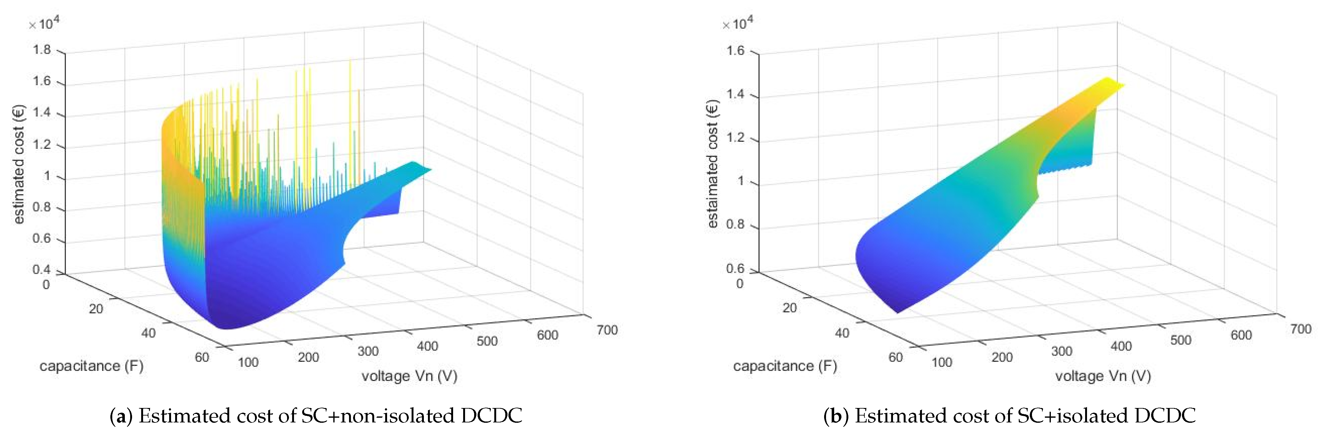
| Overall conversion power installed (kW) | 30 | c35 | 55 | |
| Voltage ratio SCC | TBD | H | L | L |
| Voltage ratio BC | H | L | H | H |
| Maximum power processed with low voltage ratio (kW) | 25 | 5 | 30 | 25 |
| Minimum power processed with high voltage ratio (kW) | 5 | 30 | 5 | 30 |
| Application | Voltage Support | Distribution Power Quality | Peak Shaving | Energy Time Shifting | |
|---|---|---|---|---|---|
| Hybrid Component | PC | PC | PC | PC/EC | |
| Island grids | EC | Improving transient response, increase efficiency/performance and lifetime of the EC, grid (voltage) quality, supply security [63,64,65] | Operational limits operation, self sufficiency, economic efficiency, efficiency, reduce energy costs [66,67] | ||
| Uninterruptible Power Supply | EC | Utilization of UPS EC, economic efficiency, stability of power system [68] | |||
| Peak Shaving | EC | Minimizing the power fluctuation, self-sufficiency, grid quality, optimizing the capacity ratio of EC, PC [69] | Dimensioning, efficiency, economic efficiency, lifetime, smoothing the current of EC [70] | ||
| Energy time shifting | EC | Dimensioning, efficiency, economic efficiency, lifetime, smoothing the fluctuation of RE [71] | Self-sufficiency, reduce of max. power consumption/generation, utilization of RE, efficiency, dimensioning, lifetime [72] | ||
| Energy Trading/Arbitrage | EC/PC | Economic efficiency (operational costs), efficiency, reduce energy costs [73] |
| Predicted Data | Prediction Techniques | Evaluation Metrics |
|---|---|---|
| Charging demand [80,81,82] | CNN, LSTM, RNN | MAPE, MAE, NRMSE |
| RE production [75,76,77,79] | CNN, MILP, NN, RNN, ARIMA, GAN, MLP, LSTM | MAPE, RMSE |
| ESS Capacity [78,79] | MILP, MINLP, NN | RMSE |
| Charging scheduling and pricing [83,84] | MILP, RL, ANN | N/S |
| Charging station placement [85,86] | GA, RL, Linear Regression, Decision Trees | N/S |
| Paper | Energy Storage System | Electric Topologies | Optimization | General Control Techniques | Used Data | |
|---|---|---|---|---|---|---|
| Optimization Function | Real Time | |||||
| [9] | (H/Br) RFB, SC | DC coupled | Power | Yes | Mathematical model | Microgrids |
| [87] | Battery, SC | DC coupled | Power allocation of different ESS | Yes | Classical Real-time optimization | Microgrids/Simulated |
| [4] | Battery, SC | DC coupled | Reduces measurement inaccuracies | N/S | Classical | N/S |
| [8] | VRFB, SC | Active topology | Current, SoC | No | Classical Fuzzy logic | EV charging park/Real |
| [5] | Li-Ion battery, SC | DC coupled | N/S | N/S | Fuzzy logic | Ships |
| [88] | VRFB, SC | Active topology | Power thresholds | No | Rule-based | Industrial grid—Real/Synthetic EV charging park |
| [63] | Batteries, SC | DC coupled | Constant voltage to the DC bus | No | Classical | PV, AC- and DC Loads/Simulated |
| [89] | Battery, SC | DC coupled | N/S | N/S | Global optimization Real-time optimization | Electric vehicle |
| [90] | Li-Ion battery, SC | DC coupled | Meet power demand Reduce the cost of energy storage device | Yes | Classical Real-time optimization | Ship load |
| [91] | Battery, SC | DC coupled | Power allocation | Yes | Classical Rule-based | EV application |
| [64] | Fuel cell, Battery, SC | DC coupled | Provide power for load in time Good tracking performance of HESS current Obtain a stable voltage of the dc bus | Yes | Projection operator adaptive law | N/S |
| [69] | Battery, SC | DC coupled | Minimizing the power fluctuation Optimizing the capacity ratio of each ESS | Yes | Real-time optimization | N/S |
| [92] | Battery, SC | N/S | N/S | Yes | Rule-based Global optimization Real-time optimization | Electric vehicle |
| [93] | battery, SC | DC coupled | Power Charge/Discharge cycle | Yes | Real-time optimization | PV power generation |
| [67] | Li-Ion battery, SC | AC coupled | Optimize the cycle life of the HESS | Yes | Mathematic model | Microgrids |
| [72] | Battery, SMES | DC coupled | Control charge/discharge prioritization | No | Classical | Off-grid load profile/Simulated Sea wave energy conversion/Simulated |
| [68] | Battery, fuel cell, | AC coupled, On grid | Power | N/S | N/S | Grid data/Real |
| [94] | Battery, SC | Three-level NPC Converter | N/S | N/S | Classical | Electric vehicle |
| [71] | Battery Superconducting magnetic ESS | One DC/AC converter Two DC/ DC converters | Smoothing the fluctuations of the wind power output | N/S | Device/system-level control strategies | Wind power generation |
| [95] | Battery, SC | DC coupled | N/S | N/S | Rule-based | Electric vehicle |
| [73] | Battery, fuel cell, electrolyzer | DC coupled, On grid AC | Energy costs, power | N/S | Rule-based | Predicted daily data |
| [66] | Fuel cell, battery, SC | DC coupled, Off grid | Power | Yes | Real-time optimization | Grid data/Real |
| [65] | Battery, SC | DC coupled | N/S | N/S | Microgrid | |
| [96] | PbA and Li-Ion battery, SC | Three different architectures | Maintain the grid power and voltage | No | Classical | Residential load/Literature data |
| [97] | battery, SC | DC coupled | Current, voltage | Yes | Real-time optimization | N/S |
| [98] | Fuel cell, SC | DC converters | Voltage | No | Classical | Electric vehicle/Simulated |
| [70] | Battery, SMES | DC coupled, On grid | Current | N/S | N/S | Grid data/Real |
| [99] | Fuel cell, Battery, Electrolyzer | AC bus and DC bus considered | N/S | Yes | Real-time optimization | Residential load |
| Real-Time EMS Control Techniques | Advantages | Limitations | ||
|---|---|---|---|---|
| Classical | Filtration [91] |
|
| |
| Intelligent | Rule-based | Fuzzy logic [88,91,92,95] |
|
|
| Real-time optimization | MPC [7,92,97] |
|
| |
| NN [7,77] |
|
| ||
| RL [85] |
|
| ||
| PSO [69,89] |
|
| ||
Disclaimer/Publisher’s Note: The statements, opinions and data contained in all publications are solely those of the individual author(s) and contributor(s) and not of MDPI and/or the editor(s). MDPI and/or the editor(s) disclaim responsibility for any injury to people or property resulting from any ideas, methods, instructions or products referred to in the content. |
© 2023 by the authors. Licensee MDPI, Basel, Switzerland. This article is an open access article distributed under the terms and conditions of the Creative Commons Attribution (CC BY) license (https://creativecommons.org/licenses/by/4.0/).
Share and Cite
Schubert, C.; Hassen, W.F.; Poisl, B.; Seitz, S.; Schubert, J.; Oyarbide Usabiaga, E.; Gaudo, P.M.; Pettinger, K.-H. Hybrid Energy Storage Systems Based on Redox-Flow Batteries: Recent Developments, Challenges, and Future Perspectives. Batteries 2023, 9, 211. https://doi.org/10.3390/batteries9040211
Schubert C, Hassen WF, Poisl B, Seitz S, Schubert J, Oyarbide Usabiaga E, Gaudo PM, Pettinger K-H. Hybrid Energy Storage Systems Based on Redox-Flow Batteries: Recent Developments, Challenges, and Future Perspectives. Batteries. 2023; 9(4):211. https://doi.org/10.3390/batteries9040211
Chicago/Turabian StyleSchubert, Christina, Wiem Fekih Hassen, Barbara Poisl, Stephanie Seitz, Jonathan Schubert, Estanis Oyarbide Usabiaga, Pilar Molina Gaudo, and Karl-Heinz Pettinger. 2023. "Hybrid Energy Storage Systems Based on Redox-Flow Batteries: Recent Developments, Challenges, and Future Perspectives" Batteries 9, no. 4: 211. https://doi.org/10.3390/batteries9040211