
Pulsed Current Constructs 3DM Cu/ZnO Current Collector Composite Anode for Free-Dendritic Lithium Metal Batteries


College of Material Science and Engineering, Zhejiang University of Technology, Hangzhou 310014, China
*
Authors to whom correspondence should be addressed.
Batteries 2023, 9(3), 188; https://doi.org/10.3390/batteries9030188
Submission received: 31 January 2023
/
Revised: 7 March 2023
/
Accepted: 20 March 2023
/
Published: 22 March 2023
(This article belongs to the Section Battery Materials and Interfaces: Anode, Cathode, Separators and Electrolytes or Others)
Abstract
:Although lithium metal is an ideal anode material for achieving high-energy-density lithium-based batteries, the uneven deposition/exfoliation process of lithium during cycling easily triggers the formation of lithium dendrites and dead lithium, which leads to a low Coulombic efficiency and safety issues. In this paper, a lithiophilic 3D copper mesh current collector is designed by using lithiophilic ZnO and pulsed current plating and is applied to a lithium metal battery composite anode. Under the action of the pulsed current field, the novel lithium metal composite anode battery achieved the homogeneous deposition of lithium ions. The lithium-to-copper half cells assembled with the 3DM Cu/ZnO current collector from the pulsed current deposition presented a Coulombic efficiency as high as 97.8% after 1 min of activation at 3 mA cm−2 follow by 10 cycles at a stripping current of 0.5 mA cm−2. Moreover, the symmetric cell could be stable for 1500 h at 1 mA cm−2 with a limited capacity of 1 mAh cm−2, and the assembled full cell (LiFePO4 as the cathode) maintained a Coulombic efficiency of about 90% for the 30th cycle at 1 C. This novel mechanism is an advanced strategy to improve cyclic stability and is crucial for designing stable lithium metal batteries.
1. Introduction
Focusing on increasing the energy density of rechargeable lithium-ion batteries (LIBs), lithium metal with a high theoretical specific capacity (3860 mAh g−1) and low redox potential (−3.040 V vs. standard hydrogen electrode) have been extensively investigated [1,2,3,4]. However, uncontrollable lithium dendrite growth and dead lithium (inactive lithium) generation during repeated cycles lead to instability at the lithium metal anode interface, which results in a waste of lithium resources, a low Coulombic efficiency (CE), and even incurs safety hazards, which seriously restrict their practical applications [5,6,7,8]. Many efforts such as the construction of three-dimensional (3D) skeletal structures, loads with lithiophilic active sites, prepositioned artificial solid electrolyte interphases (SEI), and separator modifications have been devoted to tackle the above issues [9,10,11,12,13]. However, the continuous loss of lithium metal due to the formation of dead lithium and electrolyte side reactions is still unavoidable during the plating/stripping of lithium metal anodes [14,15]. This will lead to a rapid loss in the anode volume and growth in the interface impedance, which may even further incur rapid capacity decay and safety concerns [16,17,18]. Therefore, reducing the irreversible lithium loss and thus maintaining the lithium inventory in lithium metal cells has a crucial role in improving cycle stability and CE.
The effective control of the lithium plating/stripping process by improving the stability of the composite anodes for lithium metal batteries, complemented by the modification of the electrochemical environment and optimization of the collector structure, is one of the best practical strategies to alleviate the above problems [19,20,21,22]. In fact, for lithium anodes, the lithium deposition process depends heavily on the substrate, and the lithium plating on the Cu substrate is more reversible and denser than that on the lithium substrate, which facilitates the maintenance of a high volumetric capacity and efficient lithium utilization [23,24,25,26]. Combined with the construction of the above 3D porous skeleton structure, it can provide a sufficiently large specific surface area for lithium metal deposition and effectively accommodate the volume variation in the lithium metal, which thus inhibits the growth of the lithium dendrites [27,28,29,30]. In addition, the 3D conductive network helps to mitigate the polarization by reducing the local current density of the electrode [31,32]. Nevertheless, the lithium metal deposition layer is weakly bonded to the lithiophilic 3D conductive network, which tends to clump or peel off from the matrix during the plating/stripping process [33]. Therefore, lithiophilic active materials such as ZnO, which can reduce the barriers to lithium nucleation, are often coated on the 3D conductive substrate to induce more stable lithium deposition [34,35]. In addition, some additional applied physical fields have been proven to improve the deposition state of lithium metal [36,37]. Gu et al. grew in situ Cu matrix clusters with a tunable oxidation state in Cu3(DMPz)3 by using a simple pulsed method and achieved a high CO2RR performance and ultralong cycling by enhancing their selectivity to C2H4 [38]. Zai et al. also prepared Te nanowires with a uniform morphology by controlling the nucleation and growth of crystals via pulsed physical deposition [39]. Among them, the pulsed current, due to its relaxation phenomenon, can cause Li+ to form a uniform and dense deposition layer on the lithium metal surface, which effectively inhibits the growth of lithium dendrites and the generation of volume expansion and improves the cycle stability of the battery [40,41]. At the same time, not only will this new strategy not destroy the internal structure of the battery, but also the experimental setup is simple and the cost is lower, which is conducive to more in-depth and convenient research on the battery.
In this work, we developed a strategy for pulsed current lithium plating that enables high-performance lithium metal composite anode batteries. The copper mesh with a regular ordered woven structure was used as a 3D current collector for lithium storage, and its lithiophilic property was improved by the electrochemical deposition of ZnO nanosheet layers. Finally, a lithium metal anode with a high-density uniform lithium plating layer was constructed via the pulsed current preplating of lithium metal. As a result, the lithium-to-copper (Li-Cu) half cell assembled with the obtained 3DM Cu/ZnO@Li-P composite anode maintained a CE above 97.8% after 1 min of activation at 3 mA cm−2 and 10 cycles of stripping at 0.5 mA cm−2, while the 3DM Bare Cu@Li composite anode remained only 92.3% under the same conditions. Similarly, the results for lithium-symmetric (Li-Li) batteries showed that the 3DM Cu/ZnO@Li-P composite anode retained a low cycling overpotential after 1500 h, while the 3DM Bare Cu@Li composite anode failed after 250 h due to excessive polarization potential. In addition, the full cell assembled with the above lithium metal anode (LiFePO4 as the cathode) achieved a Coulomb efficiency retention of about 90% at the 30th cycle. This fully demonstrates the rationality of the design of the 3D lithiophilic anode and the excellent effect of pulsed current plating in promoting uniform Li+ deposition and inhibiting lithium dendrite growth.
2. Materials and Methods
2.1. Material Preparation
2.1.1. Fabrication of 3DM Cu/ZnO Current Collector
All reagents were used directly as received (Table S1). The square copper mesh cut into 20 mm × 30 mm was firstly washed with 0.1 M dilute hydrochloric acid for 1 min, then washed with deionized water and ethanol, and vacuum dried. The zinc foil was cut into the same size.
We dissolved 2 M ZnSO4·7H2O and 0.2 M MnSO4 in deionized water and ultrasonic dispersion for 30 min to obtain a colorless transparent liquid. Then, the zinc foil and copper mesh (the original mass was 0.0701 g) were used as the counter and working electrodes and were put into the electrolyte for plating. The loading of the coating was 10 mAh cm−2. The plated products were thoroughly washed and dried. Finally, the samples (the mass before oxidation was 0.0846 g) were annealed at 225 °C under air atmosphere for 2 h. After cooling, the 3DM Cu/ZnO current collector was obtained (the mass of Cu/ZnO was 0.0843 g).
2.1.2. Fabrication of 3DM Cu@Li, Cu/ZnO@Li-N, and Cu/ZnO@Li-P Composite Anodes
The circular copper mesh collector cut to a diameter of 15 mm was used as the cathode, and the lithium foil was used as the anode for lithium plating at 6 mAh cm−2 to obtain the 3DM Bare Cu@Li and 3DM Cu/ZnO@Li-N composite anodes. Similarly, 3DM Cu/ZnO was lithium plated by setting the plating current as the pulsed current with a duty cycle of 1s:1s to obtain the 3DM Cu/ZnO@Li-P composite anode.
2.2. Material Characterization
RIGAKU D/Max 2550 PC with a Cu Kα radiation source (λ = 1.5406 Å) was used to collect X-ray diffraction (XRD) data of the materials to characterize their detailed phase structures. Hitachi S-4700 field emission scanning electron microscopy (FESEM) operating at 15 kV was used to observe the morphology and surface structure of the samples. Energy-dispersive X-ray spectroscopy (EDX) mapping was used to determine the distribution of the elements.
2.3. Electrochemical Measurements
The CR2032 coin cell was assembled by using the 3DM Cu@Li, Cu/ZnO@Li-N, and Cu/ZnO@Li-P current collectors as the electrodes, the copper foam and copper mesh as the counter electrodes, the polypropylene membrane as the separator, and by adding a commercial lithium battery electrolyte. The assembly process was carried out in an argon-filled glove box. The cutoff voltage range used for charging and discharge was −1.0 to 1.0 V (vs Li+/Li). In the full cells test, 3DM Cu@Li-N, Cu/ZnO@Li-N, and Cu/ZnO@Li-P were used as the anodes and LiFePO4 as the cathode. Among them, the mass ratio of LiFePO4, Super P, and polyvinylidene difluoride in the cathode was 8:1:1. Electrochemical impedance spectroscopy (EIS) was tested at the range from 0.01 to 104 Hz. For the CE testing of the Li-Cu batteries after “dead lithium” activation, lithium stripping at 0.5 mA cm−2 was performed after 1 min of activation at 3 mA cm−2 [42].
3. Results
3.1. Material Characterization
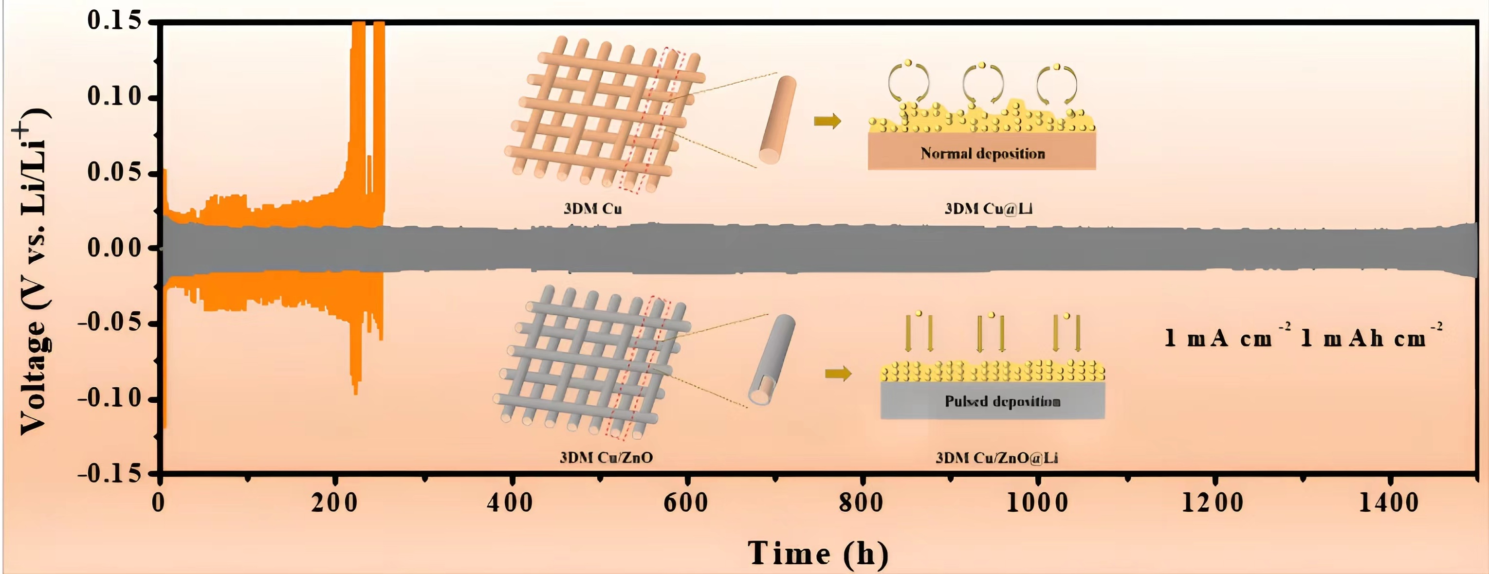
Schematic diagrams of the woven layer structure of a commercial copper mesh before and after the electrodeposition of ZnO are shown in Figure 1a,b. A 3DM Cu/Zn structured collector loaded with zinc nanosheets was obtained via the in situ electrodeposition of Zn on the surface of a commercial 3D copper mesh current collector (Figure 1b and Figure S1). The zinc layer on the surface was further oxidized via oxidation annealing to form a zinc oxide structure (3DM Cu/ZnO). The corresponding optical photographs and SEM images of Cu and Cu/ZnO are shown in Figure 1c–j. It is obvious that the initial commercial copper network presented a relatively smooth surface (Figure 1c,e,f), while the color of the Cu/Zn surface changed to bright gray when uniformly covered by zinc nanoflakes (Figures S2 and S3). Upon further oxidation, the Zn nanosheets gradually disappeared and were replaced by a faintly visible structure of uniform and dense layers of dark gray oxide nanoparticles (Figure 1d,h,i). The uniform distribution of the Zn and O elements observed in the EDS mapping (Figure 1g,j) and the typical peak intensities of the Cu/Zn and Cu/ZnO revealed in XRD (Figure S4) fully confirmed the successful preparation of the ZnO layer on the copper network.
3.2. Deposition Morphology
To observe the effect of the nucleation buffer layer on lithium deposition, lithium plating experiments were performed using 3DM Bare Cu and 3DM Cu/ZnO at 0.5, 1, and 2 mA cm−2. The nucleation overpotential in the constant current electroplating was defined as the difference between the bottom of the voltage drop and the flat voltage plateau. Figure S5 shows that the initial Li nucleation overpotential of the 3DM Bare Cu was significantly higher than that of 3DM Cu/ZnO, which indicated that the introduction of the ZnO composite layer effectively reduced the nucleation barrier for lithium plating on the 3DM Cu current collectors, which suggests an improvement in the lithiophilic properties.
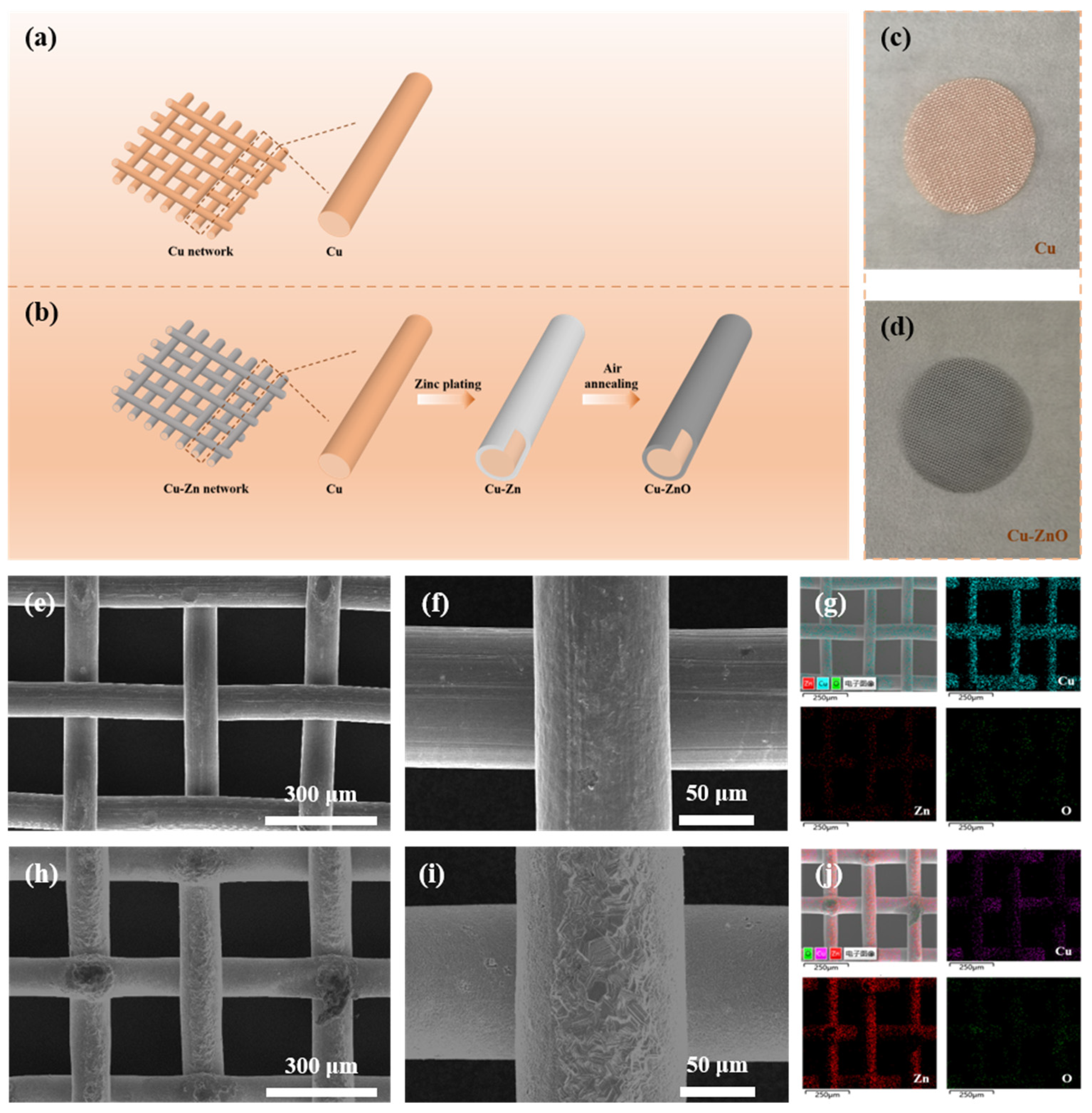
To further analyze the morphological evolution of Li during normal and pulsed current deposition, we used a 3DM Bare Cu and 3DM Cu/ZnO mesh current collector as the working electrode and lithium metal as the counter electrode for Li plating at a current density of 1 mA cm−2. As shown in Figure 2 and Figure S6, we distinguished the plating process into three stages according to the deposition duration, and the morphology of the normal lithium plating and the pulsed current plating was almost identical during the plating process at 1 and 3 mAh cm−2 (stage Ⅰ and Ⅱ, Figure 2b,c,e,f). As plating proceeded up to 6 mAh cm−2 (stage Ⅲ), the optical image of 3DM Bare Cu showed obvious cracks, while 3DM Cu/ZnO exhibited a relatively uniform smooth and glossy lithium metal surface (see insets in Figure 2d,g). The microstructure also showed that the 3DM Cu/ZnO surface deposition exhibited more regularity, and the porous structure of Cu/ZnO was still well preserved, which indicated the ability of this composite layer to accommodate lithium metal and prevent large volume changes during deposition. This was probably due to the rough surface of the bare copper mesh triggering the uneven distribution of the current, which led to the disordered deposition of lithium. The difference is that the pulsed current deposition of Cu/ZnO facilitated the suppression of polarization during lithium deposition, which in turn induced the orderly and dense plating of lithium and inhibited the lithium dendrites growth, as shown in the related deposition schematic in Figure S7.
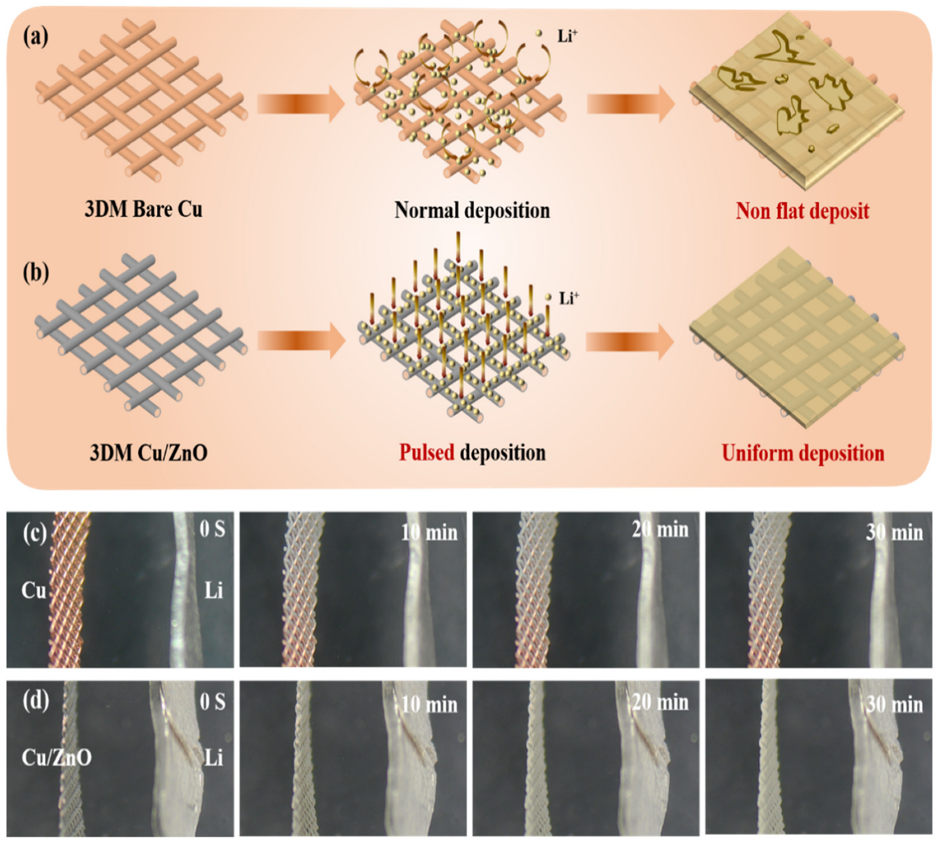
Figure 3a,b shows a comparison of the lithium deposition processes on the 3DM Cu and Cu/ZnO current collectors in the presence or absence of a pulsed current. In the lithium electroplating process, ideally, Li+ was deposited on the surface of the 3DM Bare Cu and Cu/ZnO mesh current collectors. However, concentration polarization will inevitably occur due to the slow conduction of Li+. The sluggish electroplating reaction will result in the accumulation of a large number of electrons on the Cu side, which is especially true for the tiny protrusions, which eventually trigger the growth of lithium dendrites. Instead, during the pulsed electroplating process, lithium ions tend to aggregate in the Ton stage and deposit on the surface of the 3DM Cu/ZnO mesh current collector. Since the Ton time is set relatively short, the small amount of tip aggregation of lithium ions can spread uniformly around the 3DM Cu/ZnO protrusions during the Toff resting time and thus reduce the polarization phenomenon. In addition, the complementary ZnO lithiophilic layer can further smooth the deposition process of lithium ions, which allows the safety and cycle performance of the battery to be improved. The deposition of lithium ions on different substrates was verified via in situ observations. The results showed that the surface of the 3DM Bare Cu current collector could not be adequately covered during the initial stage of the lithium ions deposition, which thus led to a loose and partially thickened lithium layer (Figure 3c). In contrast, with the application of the pulsed current and ZnO lithiophilic layer, the lithium deposition layer always maintained a dense and uniform morphology as the thickness increased, as seen in Figure 3d.
3.3. Electrochemical Performance Testing
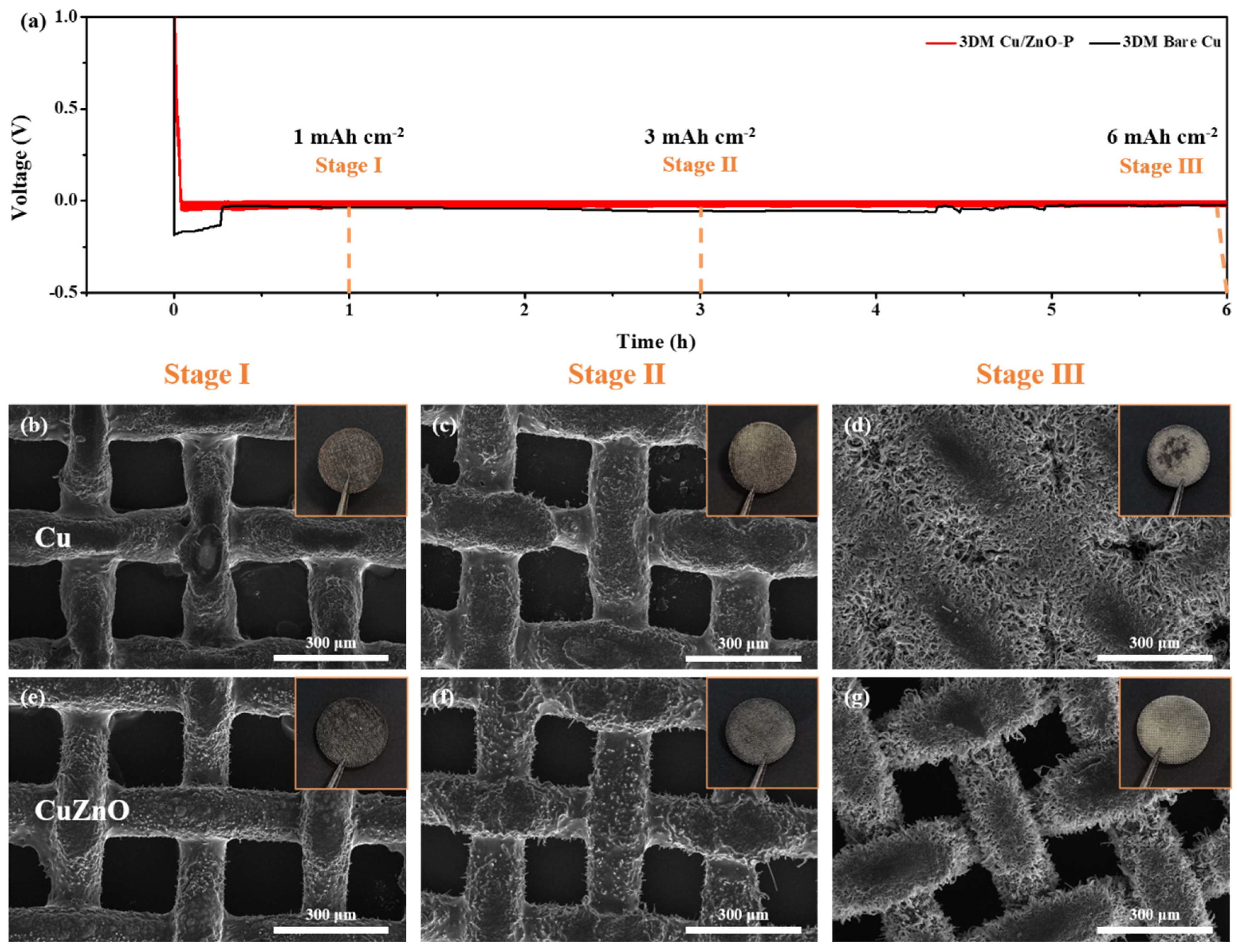
In fact, “dead lithium” is always unavoidable during the cycling of lithium metal batteries. To verify the superiority of 3DM Cu/ZnO collectors under pulsed currents, we designed a rapid delithiation process after lithium deposition based on a simple method described in the literature. The lithium layer was first deposited with a high current and then stripped with only a low current to probe the effect of “dead lithium” on CE in Li-Cu half cells assembled with different collectors. After 1 min of activation at 3 mA cm−2 and 10 cycles with a stripping current of 0.5 mA cm−2, the CE for the normal deposition of the Li-Cu battery assembled with the 3DM Bare Cu current collector was only 92.3% (Figure 4a). For the Li-Cu/ZnO (3DM) current collector battery, it exhibited a high CE of 96.9% (Figure 4b), and its substantially reduced Li ion nucleation potential further confirmed the advantage of the enhanced lithiophilic nature brought by ZnO. The Li-Cu/ZnO (3DM) with a pulsed current used to deposit lithium presented the best CE up to 97.8%, which demonstrated that the pulsed current could facilitate the recovery of “dead lithium”, which helps the battery achieve long cycles (Figure 4c). Further, since the 3DM Cu/ZnO@Li composite anode achieved a high mass, large density loading of lithium, a high areal capacity of 5.98 mAh cm−2 was maintained after being discharged to −1 V versus Li/Li+ under 0.5 mA cm−2, as shown in Figure 4d. In addition, the comparison of the discharge deposition voltages could also indicate that the 3DM Cu/ZnO@Li-P composite anode had a lower nucleation overpotential. The cycling stabilities of the half cell assembled with two composite anodes at 1 mAh cm−2 for different currents are shown in Figure S8. For the Cu@Li composite anode, the CE was 96.3% and 79.4% for the first and 100th cycles, respectively, at a current density of 0.5 mA cm−2, while the 3DM Cu/ZnO@Li-P composite anode was still maintained at 97.6% CE after 170 cycles (Figure S8a). Even when the current density increased to 1 mA cm−2, the CE of the Cu/ZnO@Li-P composite anode started to fluctuate until after 125 cycles, and it remained as high as 98.4% after 150 cycles (Figure S8b). Under a current density of 2 mA cm−2, the half cell with an applied 3DM Cu/ZnO@Li-P anode exhibited a high CE of 94.4 % for the 110th cycle, as shown in Figure S8c, which demonstrated that the 3DM Cu/ZnO@Li-P anode could contribute to the long cycle performance of the half cell. Figure 4e–h and Figure S9 show the SEM comparisons of the 3DM Cu@Li-N and Cu/ZnO@Li-P anodes after 25 and 50 cycles of the half cell, which further explains the enhancement mechanism of the pulsed current plating Li on the electrochemical performance of the Cu/ZnO mesh current collector as an anode. As illustrated, for the 3DM Cu@Li-N anode, the current collector had a rough surface and was almost completely covered with uneven deposits (Figure 4e,f and Figure S9a,c). However, for the Cu/ZnO@Li-P anode, the surface of the current collector surface remained uniform and flat (Figure 4g,h and Figure S9b,d). Such a high CE and low nucleation overpotential 3DM Cu/ZnO@Li-P composite anode can help the battery exhibit a higher specific capacity compared to the 3DM Cu@Li composite anode, which offers exciting possibilities for highly rechargeable lithium metal fabrication methods.
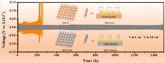
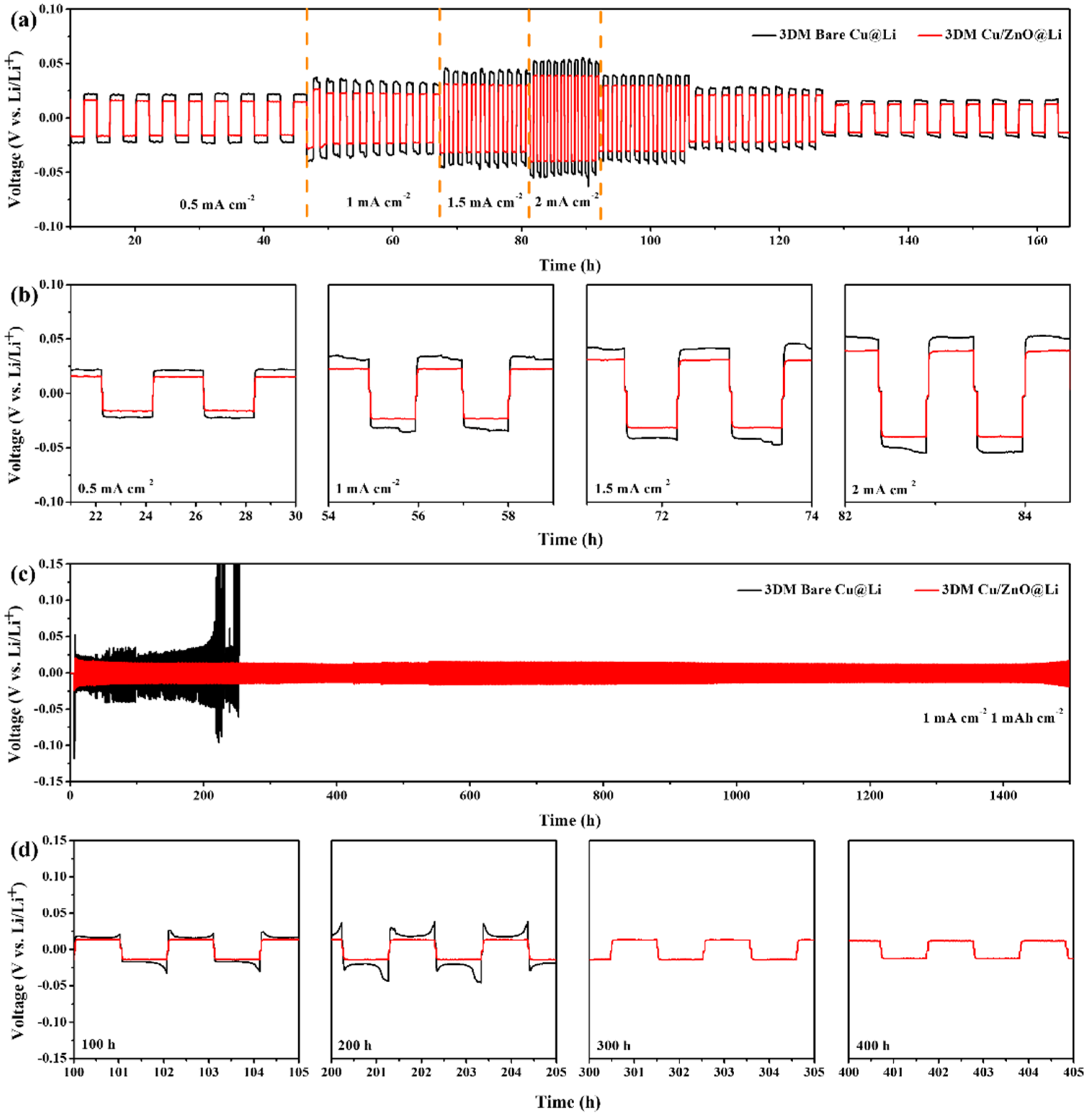
According to the results of the above lithium plating, the advantages of the uniform deposition of the pulsed current on the surface of the 3DM Cu/ZnO current collector was particularly significant. As shown in Figure 5, the cycling stability and rate capability of the 3DM Cu/ZnO current collector-based lithium metal anode were greatly improved under the pulsed current. For the long-term constant current discharge/charge tests, the lithium capacities of 6 mAh cm−2 each were first deposited on the 3DM Cu and Cu/ZnO mesh current collectors at a current density of 1 mA cm−2. Figure 5a,b shows the rate performance of the symmetric cells from 0.5 to 2 mA cm−2. The overpotential of the pulsed current lithium plating (3DM Cu/ZnO@Li-P) remained low at 78 mV even at 2 mA cm−2, and it could go back to below 25 mV when the current density was reduced to 0.5 mA cm−2. In contrast, the battery assembled with the Cu network current collector with normal lithium plating (3DM Bare Cu@Li) exhibited higher overpotentials of 104 and 36 mV for current densities of 2 and 0.5 mA cm−2, respectively. In addition, the 3DM Cu/ZnO@Li-P composite anode battery achieved excellent cycle performance at 1 mA cm−2 and maintained an overpotential of 27 mV even after cycling for 1500 h, which was better than that previously reported in the literature (Table S2), see Figure 5c. Nevertheless, the voltage of the 3DM Cu@Li composite anode started to fluctuate at 218 h. In particular, the gradual formation of an inhomogeneous solid electrolyte interface layer (SEI) occurred due to the large consumption of electrolytes and the formation of impurities. In the process of starting the cycle, the hysteresis voltage was unstable and the symmetrical battery with a 3DM Cu/ZnO@Li-P composite anode assembly performed better. In the subsequent cycle, the irregular consumption of the anode was further avoided, and the stable cycling was achieved as the pulsed current promoted the uniform deposition of the lithium ion on the current collector (Figure 5d). For the composite anode after normal plating, there was an obvious voltage hysteresis effect, which triggered a rapid rise in overpotential, and its uneven surface was more likely to form “dead lithium”, which thus seriously affected the stability of the symmetric cell during cycling.
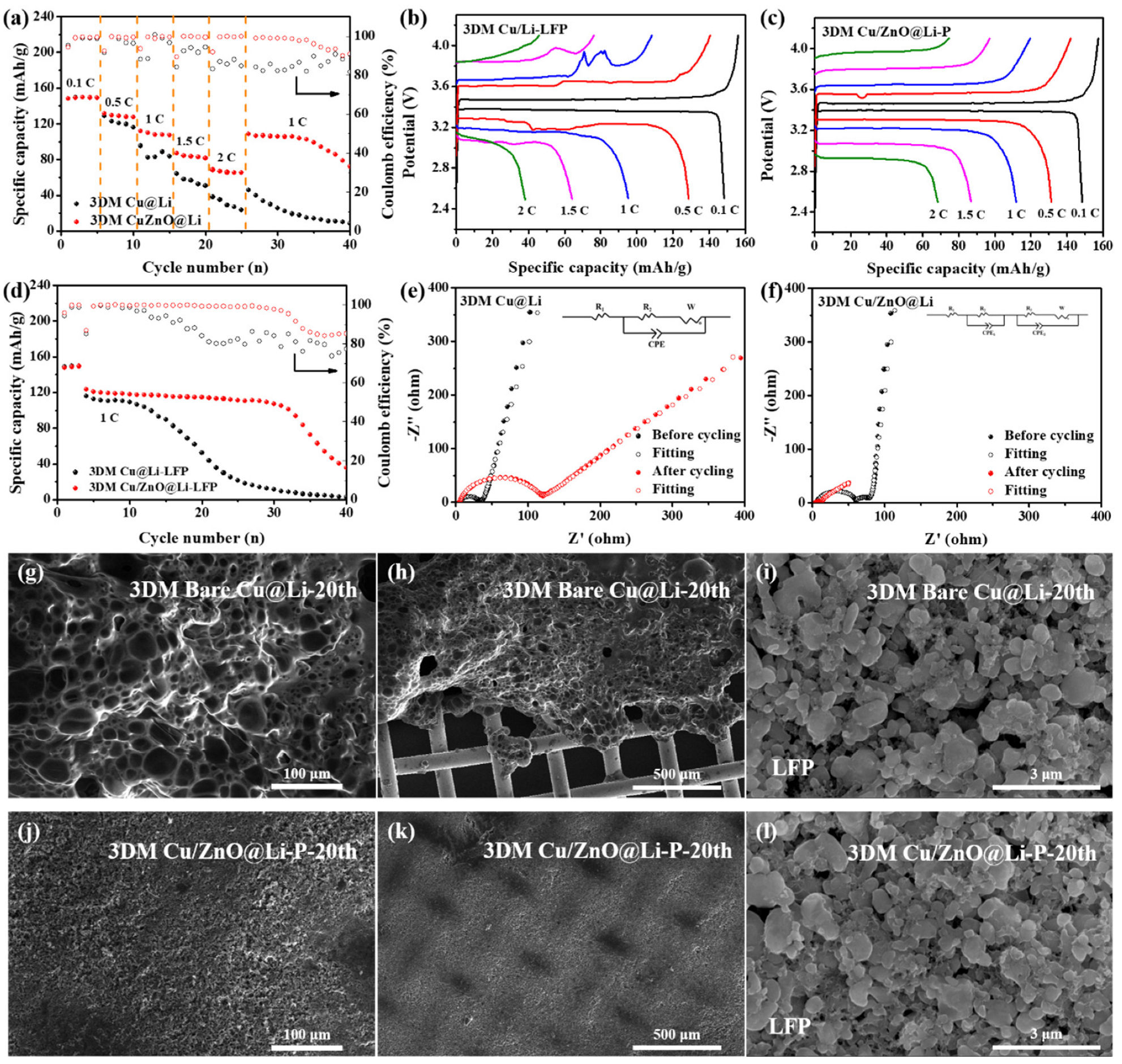
To further investigate potential practical applications, full cells were fabricated with 3DM Cu and Cu/ZnO mesh current collectors that were electroplated with lithium at a current density of 1 mA cm−2 for 6 h as the anode and commercial LiFePO4 (1.58 mAh cm−2) as the cathode for evaluation (3DM Cu/ZnO@Li-P (or Cu@Li), Figure 6). As shown in Figure 6a, the rate performance of the full cell with the application of the 3DM Cu/ZnO@Li-P composite anode can be significantly improved. The specific capacity reached 68.4 mAh g−1 at 2 C and remained 108.5 mAh g−1 when returning to 1 C. In contrast, the rate capacity of the Cu@Li-N anode was only 38.1 mAh g−1 at 2 C and 45.7 mAh g−1 when returning to 1 C. The voltage profiles of the full cells assembled by the 3DM Cu@Li and Cu/ZnO@Li-P composite anodes at different rates are shown in Figure 6b,c. As the rate increased, the charging plateau of 3DM Cu/ZnO@Li-P gradually rose, while 3DM Cu@Li rose rapidly, which corresponds to the difference in their rate performance. The capacity of the 3DM Cu/ZnO@Li-P full cell was maintained at 107.4 mAh g−1 after 30 cycles, with a CE retention rate of 97.5%. However, the capacity of the 3DM Cu@Li rapidly dropped to 11.4 mAh g−1 after 30 cycles, as shown in Figure 6d. We also tested the full cell cycling performance of the composite anode at a high lithium loading capacity (18 mAh cm−2), which maintained 95% CE after 80 cycles (Figure S10). In addition, electrochemical impedance spectroscopy (EIS) was used to explore the charging transfer resistance of lithium ions at the interface. Figure 6e,f show the Nyquist fitting data corresponding to the two current collector anodes before the test and after 20 cycles, and the simulation parameters from the equivalent circuit are listed in Table S3. After 20 cycles, the apparent decrease in resistance of the full cell could be attributed to the formation of SEI. For the 3DM Cu@Li and 3DM Cu/ZnO@Li-P composite anodes obtained after 20 cycles, their SEM comparison showed the superiority of the pulsed current plating Li on the 3DM Cu/ZnO current collector as an anode. For the 3DM Cu/ZnO@Li-P composite anode, the current collector surface remained uniformly flat (Figure 6g–l and Figure S11). Meanwhile, the lithium-oxygen batteries constructed with the 3DM Cu/ZnO@Li-P composite anode also demonstrated its excellent performance (Figure S12). In summary, the 3DM CuZnO@Li-P composite anode successfully inhibited the lithium dendrites and greatly improved the electrochemical performance.
4. Conclusions
In summary, this study proposes a pulsed current preplating method to achieve high-performance anode-free lithium metal batteries. The lithium deposition overpotential of the copper mesh was reduced by the introduction of the lithiophilic ZnO layer, and the regulation of the Li+ transfer and distribution were reached by applying a pulsed current to achieve a uniform deposition. The results showed that the Li-Cu/ZnO (3DM) obtained by applying the pulsed current for lithium deposition had a high CE when used in half cells, and it remained above 97.8% for 10 cycles of Li stripping at 0.5 mA cm−2 after 1 min of activation at 3 mA cm−2. In addition, the symmetric cell with the 3DM Cu/ZnO@Li-P composite anode could cycle stably for more than 1500 h at 1 mA cm−2 with a limited capacity of 1 mAh cm−2. The assembled full cell (Li-LiFePO4) maintained a Coulombic efficiency of about 90% after 30 cycles at 1 C. This implies that the 3DM Cu/ZnO current collector possessed excellent advantages when used as a lithium-free anode by applying pulsed current preplating for the uniformity of Li+ deposition. This strategy provides a more reasonable alternative method for the development of anode-free lithium metal batteries.
Supplementary Materials
The following supporting information can be downloaded at https://www.mdpi.com/article/10.3390/batteries9030188/s1. Table S1. The supplier of raw materials, Figure S1. Schematic diagram of preparation of zinc oxide coating, Figure S2. SEM image of (a) 3DM Cu, (b) 3DM Cu/Zn, (c) 3DM Cu/ZnO and (d) Sample comparison, Figure S3. The cross-sectional SEM images of (a,b) 3DM Cu and (c,d) Cu/ZnO, Figure S4. XRD pattern of 3DM Cu, 3DM Cu/Zn and 3DM Cu/ZnO, Figure S5. The nucleation of 3DM Cu, 3DM Cu/Zn and 3DM Cu/ZnO at current density of 0.5, 1 and 2 mA cm−2, Figure S6. SEM images of (a–f) bare Cu and (g–l) Cu/ZnO mesh current collectors along Li plating of 1 (stage I), 3 (stage II) and 6 mAh cm−2 (stage III), Figure S7. Schematic diagram of lithium electroplating deposition, Figure S8. The CE of the 3DM Cu@Li and Cu/ZnO@Li-P composite anode during the Li plating/stripping at different current densities with the capacity of 1 mAh cm−2, Figure S9. SEM image of after 25th and 50th cycles lithium stripping which the surface of (a,c) 3DM Cu@Li anode and (b,d) 3DM Cu/ZnO@Li-P composite anode, Table S2. Comparison of the cycling performance of Li metal anodes with decorating ZnO, Figure S10. Cycling performance of full-cells with 3DM Cu/ZnO@Li-P composite anode at 1 C with three activation cycles at 0.1 C in the beginning, Figure S11 SEM images of (a) 3DM Cu@Li and (b) 3DM Cu/ZnO@Li-P composite anodes after 20 cycles lithium stripping in a full-cell, Table S3 Electrochemical parameters of the equivalent circuit for cells constructed from the prepared electrodes, Figure S12 (a) Rate performance and (b) cycle performance of lithium-oxygen batteries constructed with 3DM Cu/ZnO@Li-P composite anode. References [43,44,45,46] are cited in the supplementary materials.
Author Contributions
Conceptualization, validation, investigation, data curation, and writing—original draft, Z.Z.; validation and investigation, Q.C.; review and editing and supervision, Y.W.; review and editing and supervision, G.H.; conceptualization, resources, writing—review and editing, supervision, project administration, and funding acquisition, J.Z.; conceptualization, resources, writing—review and editing, supervision, project administration, and funding acquisition, Y.T. All authors have read and agreed to the published version of the manuscript.
Funding
This work was financially supported by the National Natural Science Foundation of China (Grant Nos. 52202313, 52202315 and 52271039), the Zhejiang Provincial Natural Science Foundation of China (Grant No. LQ22E020005 and LZ22E010002), and the State Key Laboratory of Advanced Technologies for the Comprehensive Utilization of Platinum Metals (SKL-SPM-202009).
Institutional Review Board Statement
Not applicable.
Informed Consent Statement
Not applicable.
Data Availability Statement
The data are contained within the article.
Conflicts of Interest
The authors declare no conflict of interest.
References
- Zhou, B.X.; Bonakdarpour, A.; Stoševski, I.; Fang, B.; Wilkinson, D.P. Modification of Cu Current Collectors for Lithium Metal Batteries—A Review. Prog. Mater. Sci. 2022, 130, 100996. [Google Scholar] [CrossRef]
- Lyu, T.Y.; Luo, F.Q.; Wang, D.C.; Bu, L.Z.; Tao, L.; Zheng, Z.F. Carbon/Lithium Composite Anode for Advanced Lithium Metal Batteries: Design, Progress, In Situ Characterization, and Perspectives. Adv. Energy Mater. 2022, 12, 2201493. [Google Scholar] [CrossRef]
- Wang, Q.Y.; Liu, B.; Shen, Y.H.; Wu, J.K.; Zhao, Z.Q.; Zhong, C.; Hu, W.B. Confronting the Challenges in Lithium Anodes for Lithium Metal Batteries. Adv. Sci. 2021, 8, e2101111. [Google Scholar] [CrossRef] [PubMed]
- Chen, L.; Fan, X.L.; Ji, X.; Chen, J.; Hou, S.; Wang, C.S. High-Energy Li Metal Battery with Lithiated Host. Joule 2019, 3, 732–744. [Google Scholar] [CrossRef] [Green Version]
- Wang, Z.; Shi, H.; Yang, S.T.; Cai, Z.J.; Lu, H.Q.; Jia, L.T.; Hu, M.Z.; He, H.; Zhou, K.B. Oxygen Vacancy-Enriched Co3O4 as Lithiophilic Medium for Ultra-Stable Anode of Lithium Metal Batteries. J. Alloys Compd. 2021, 888, 161553. [Google Scholar] [CrossRef]
- Bao, W.Z.; Wang, R.H.; Qian, C.F.; Li, M.H.; Sun, K.W.; Yu, F.; Liu, H.; Guo, C.; Li, J.F. Photoassisted High-Performance Lithium Anode Enabled by Oriented Crystal Planes. ACS Nano 2022, 6, 17454–17465. [Google Scholar] [CrossRef]
- Cho, S.J.; Kim, D.Y.; Lee, J.I.; Kang, J.S.; Lee, H.; Kim, G.; Seo, D.H.; Park, S. Highly Reversible Lithium Host Materials for High-Energy-Density Anode-Free Lithium Metal Batteries. Adv. Funct. Mater. 2022, 32, 2208629. [Google Scholar] [CrossRef]
- Liang, P.; Sun, H.; Huang, C.L.; Zhu, G.Z.; Tai, H.C.; Li, J.C.; Wang, F.F.; Wang, Y.; Huang, C.J.; Jiang, S.K.; et al. A Nonflammable High-Voltage 4.7 V Anode-Free Lithium Battery. Adv. Mater. 2022, 34, e2207361. [Google Scholar] [CrossRef]
- Zhang, P.P.; Yang, S.; Xie, H.G.; Li, Y.; Wang, F.X.; Gao, M.M.; Guo, K.; Wang, R.H.; Lu, X. Advanced Three-Dimensional Microelectrode Architecture Design for High-Performance On-Chip Micro-Supercapacitors. ACS Nano 2022, 16, 17593–17612. [Google Scholar] [CrossRef]
- Sun, J.H.; Peng, J.Y.; Ring, T.; Whittaker-Brooks, J.; Zhu, J.; Fraggedakis, D.; Niu, J.; Gao, T.; Wang, F. Lithium Deposition Mechanism on Si and Cu Substrates in the Carbonate Electrolyte. Energ. Environ. Sci. 2022, 15, 5284–5299. [Google Scholar] [CrossRef]
- Chen, X.R.; Li, B.Q.; Zhu, C.; Zhang, R.; Cheng, X.B.; Huang, J.Q.; Zhang, Q. A Coaxial-Interweaved Hybrid Lithium Metal Anode for Long-Lifespan Lithium Metal Batteries. Adv. Energy Mater. 2019, 9, 1901932. [Google Scholar] [CrossRef]
- Sun, X.W.; Zhang, X.Y.; Ma, Q.T.; Guan, X.Z.; Wang, W.; Luo, J.Y. Revisiting the Electroplating Process for Lithium-Metal Anodes for Lithium-Metal Batteries. Angew Chem. Int. Ed. Engl. 2020, 59, 6665–6674. [Google Scholar] [CrossRef] [PubMed]
- Zhang, J.L.; Cheng, Y.; Chen, H.B.; Wang, Y.; Chen, Q.; Hou, G.Y.; Wen, M.; Tang, Y.P. MoP Quantum Dot-Modified N, P-Carbon Nanotubes as a Multifunctional Separator Coating for High-Performance Lithium-Sulfur Batteries. ACS Appl. Mater. Inter. 2022, 14, 16289–16299. [Google Scholar] [CrossRef] [PubMed]
- Qian, L.T.; Zheng, Y.; Or, T.; Park, H.W.; Gao, R.; Park, M.; Ma, Q.Y.; Luo, D.; Yu, A.P.; Chen, Z.W. Advanced Material Engineering to Tailor Nucleation and Growth towards Uniform Deposition for Anode-Less Lithium Metal Batteries. Small 2022, 18, e2205233. [Google Scholar] [CrossRef]
- Deng, W.; Yin, X.; Bao, W.; Zhou, X.F.; Hu, Z.Y.; He, B.Y.; Qiu, B.; Meng, Y.S.; Liu, Z.P. Quantification of Reversible and Irreversible Lithium in Practical Lithium-Metal Batteries. Nat. Energy 2022, 7, 1031–1041. [Google Scholar] [CrossRef]
- Luo, C.; Hu, H.; Zhang, T.; Wen, S.J.; Wang, R.; An, Y.N.; Chi, S.S.; Wang, J.; Wang, C.Y.; Chang, J.; et al. Roll-To-Roll Fabrication of Zero-Volume-Expansion Lithium-Composite Anodes to Realize High-Energy-Density Flexible and Stable Lithium-Metal Batteries. Adv. Mater. 2022, 34, e2205677. [Google Scholar] [CrossRef]
- Wu, Q.P.; Zheng, Y.J.; Guan, X.; Xu, J.; Cao, F.H.; Li, C.L. Dynamical SEI Reinforced by Open-Architecture MOF Film with Stereoscopic Lithiophilic Sites for High-Performance Lithium-Metal Batteries. Adv. Funct. Mater. 2021, 31, 2101034. [Google Scholar] [CrossRef]
- Li, L.L.; Li, S.Y.; Lu, Y.Y. Suppression of Dendritic Lithium Growth in Lithium Metal-Based Batteries. Chem. Commun. 2018, 54, 6648–6661. [Google Scholar] [CrossRef]
- Zhang, Y.J.; Wang, H.M.; Liu, X.; Zhou, C.; Li, G.R.; Liu, S.; Gao, X.P. A Dimensionally Stable Lithium Alloy Based Composite Electrode for Lithium Metal Batteries. Chem. Eng. J. 2022, 450, 138074. [Google Scholar] [CrossRef]
- Wang, H.S.; Lin, D.C.; Xie, J.; Liu, Y.Y.; Chen, H.; Li, Y.B.; Xu, J.W.; Zhou, G.M.; Zhang, Z.; Pei, A.; et al. An Interconnected Channel-Like Framework as Host for Lithium Metal Composite Anodes. Adv. Energy Mater. 2019, 9, 1802720. [Google Scholar] [CrossRef]
- Zhang, J.L.; Chen, H.B.; Wen, M.; Shen, K.; Chen, Q.; Hou, G.Y.; Tang, Y.P. Lithiophilic 3D Copper-Based Magnetic Current Collector for Lithium-Free Anode to Realize Deep Lithium Deposition. Adv. Funct. Mater. 2021, 32, 2110110. [Google Scholar] [CrossRef]
- Liu, Y.C.; Yuan, B.Y.; Sun, C.; Lu, Y.H.; Lin, X.P.; Chen, M.H.; Xie, Y.S.; Zhang, S.Q.; Lai, C. Ultralow-Expansion Lithium Metal Composite Anode via Gradient Framework Design. Adv. Funct. Mater. 2022, 32, 2202771. [Google Scholar] [CrossRef]
- Qian, J.F.; Adams, B.D.; Zheng, J.M.; Xu, W.; Henderson, W.A.; Wang, J.; Bowden, M.E.; Xu, S.C.; Hu, J.Z.; Zhang, J.G. Anode-Free Rechargeable Lithium Metal Batteries. Adv. Funct. Mater. 2016, 26, 7094–7102. [Google Scholar] [CrossRef]
- Lin, L.D.; Qin, K.; Hu, Y.S.; Li, H.; Huang, X.J.; Suo, L.M.; Chen, L.Q. A Better Choice to Achieve High Volumetric Energy Density: Anode-Free Lithium-Metal Batteries. Adv. Mater. 2022, 34, e2110323. [Google Scholar] [CrossRef]
- Lai, G.M.; Jiao, J.Y.; Fang, C.; Jiang, Y.; Sheng, L.Y.; Xu, B.; Ouyang, C.Y.; Zheng, J.X. The Mechanism of Li Deposition on the Cu Substrates in the Anode-Free Li Metal Batteries. Small 2022, 19, e2205416. [Google Scholar] [CrossRef]
- Zhang, J.L.; Chen, H.B.; Fan, B.F.; Shan, H.P.; Chen, Q.; Jiang, C.H.; Hou, G.Y.; Tang, Y.P. Study on the Relationship between Crystal Plane Orientation and Strength of Electrolytic Copper Foil. J. Alloys Compd. 2021, 884, 161044. [Google Scholar] [CrossRef]
- Li, Q.; Zhu, S.P.; Lu, Y.Y. 3D Porous Cu Current Collector/Li-Metal Composite Anode for Stable Lithium-Metal Batteries. Adv. Funct. Mater. 2017, 27, 1606422. [Google Scholar] [CrossRef]
- Li, D.D.; Xie, C.; Gao, Y.; Hu, H.; Wang, L.; Zheng, Z.J. Inverted Anode Structure for Long-Life Lithium Metal Batteries. Adv. Energy Mater. 2022, 12, 2200584. [Google Scholar] [CrossRef]
- Ryou, M.H.; Kim, S.H.; Kim, S.W.; Lee, S.Y. A Microgrid-Patterned Silicon Electrode as an Electroactive Lithium Host. Energ. Environ. Sci. 2022, 15, 2581–2590. [Google Scholar] [CrossRef]
- Lee, H.; Song, J.C.; Kim, Y.J.; Park, J.K.; Kim, H.T. Structural Modulation of Lithium Metal-Electrolyte Interface with Three-Dimensional Metallic Interlayer for High-Performance Lithium Metal Matteries. Sci. Rep. 2016, 6, 30830. [Google Scholar] [CrossRef]
- Chu, C.X.; Li, R.; Cai, F.P.; Bai, Z.C.; Wang, Y.X.; Xu, X.; Wang, N.N.; Yang, J.; Dou, S.X. Recent Advanced Skeletons in Sodium Metal Anodes. Energ. Environ. Sci. 2021, 14, 4318–4340. [Google Scholar] [CrossRef]
- Sun, C.Y.; Gao, L.; Yang, Y.H.; Yan, Z.C.; Zhang, D.M.; Bian, X.F. Ultrafast Microwave-Induced Synthesis of Lithiophilic Oxides Modified 3D Porous Mesh Skeleton for High-Stability Li-Metal Anode. Chem. Eng. J. 2023, 452, 139407. [Google Scholar] [CrossRef]
- Louli, A.J.; Eldesoky, A.; de Gooyer, J.; Coon, M.; Aiken, C.P.; Simunovic, Z.; Metzger, M.; Dahn, J.R. Different Positive Electrodes for Anode-Free Lithium Metal Cells. J. Electrochem. Soc. 2022, 169, 040517. [Google Scholar] [CrossRef]
- Liu, Y.H.; Sun, J.M.; Hu, X.Q.; Li, Y.F.; Du, H.F.; Wang, K.; Du, Z.Z.; Gong, X.; Ai, W.; Huang, W. Lithiophilic Sites Dependency of Lithium Deposition in Li Metal Host Anodes. Nano Energy 2022, 94, 106883. [Google Scholar] [CrossRef]
- Zhan, Y.X.; Shi, P.; Ma, X.X.; Jin, C.B.; Zhang, Q.K.; Yang, S.J.; Li, B.Q.; Zhang, X.Q.; Huang, J.Q. Failure Mechanism of Lithiophilic Sites in Composite Lithium Metal Anode under Practical Conditions. Adv. Energy Mater. 2021, 12, 2103291. [Google Scholar] [CrossRef]
- Shen, K.; Wang, Z.; Bi, X.X.; Ying, Y.; Zhang, D.; Jin, C.B.; Hou, G.Y.; Cao, H.Z.; Wu, L.K.; Zheng, G.Q.; et al. Magnetic Field-Suppressed Lithium Dendrite Growth for Stable Lithium-Metal Batteries. Adv. Energy Mater. 2019, 9, 1900260. [Google Scholar] [CrossRef]
- Zhang, J.L.; Zhou, Z.K.; Wang, Y.; Chen, Q.; Hou, G.Y.; Tang, Y.P. Ultrasonic-Assisted Enhancement of Lithium-Oxygen Battery. Nano Energy 2022, 102, 107655. [Google Scholar] [CrossRef]
- Zhang, X.D.; Liu, T.Y.; Liu, C.; Zheng, D.S.; Huang, J.M.; Liu, Q.W.; Yuan, W.W.; Yin, Y.; Huang, L.R.; Xu, M.; et al. Asymmetric Low-Frequency Pulsed Strategy Enables Ultralong CO2 Reduction Stability and Controllable Product Selectivity. J. Am. Chem. Soc. 2023, 145, 2195–2206. [Google Scholar] [CrossRef]
- Li, S.N.; Zhang, H.; Ruan, H.C.; Cheng, Z.H.; Yao, Y.G.; Zhuge, F.W.; Zhai, T.Y. Programmable Nucleation and Growth of Ultrathin Tellurium Nanowires via a Pulsed Physical Vapor Deposition Design. Adv. Funct. Mater. 2022, 33, 2211527. [Google Scholar] [CrossRef]
- Xiao, T.; Zhou, Z.K.; Cao, H.; Zhang, J.L.; Chen, Q.; Hou, G.Y.; Wen, M.; Tang, Y.P. Pulse Current Charging Strategy towards High Performance of Lithium-Oxygen Batteries. Surf. Interfaces 2021, 24, 101106. [Google Scholar] [CrossRef]
- Zhang, J.L.; Zhou, Z.K.; Wang, Y.; Chen, Q.; Hou, G.Y.; Tang, Y.P. Pulsed Current Boosts the Stability of the Lithium Metal Anode and the Improvement of Lithium-Oxygen Battery Performance. ACS Appl. Mater. Inter. 2022, 14, 50414–50423. [Google Scholar] [CrossRef]
- Liu, F.; Xu, R.; Wu, Y.C.; Boyle, D.T.; Yang, A.K.; Xu, J.W.; Zhu, Y.Y.; Ye, Y.S.; Yu, Z.A.; Zhang, Z.W.; et al. Dynamic Spatial Progression of Isolated Lithium During Battery Operations. Nature 2021, 600, 659–663. [Google Scholar] [CrossRef] [PubMed]
- Zhou, Y.; Zhao, K.; Han, Y.; Sun, Z.H.; Zhang, H.T.; Xu, L.Q.; Ma, Y.F.; Chen, Y.S. A Nitrogen-Doped-Carbon/ZnO Modified Cu Foam Current Collector for High-Performance Li Metal Batteries. J. Mater. Chem. A 2019, 7, 5712. [Google Scholar] [CrossRef]
- Sun, C.Z.; Li, Y.P.; Jin, J.; Yang, J.H.; Wen, Z.Y. ZnO Nanoarray-Modified Nickel Foam as a Lithiophilic Skeleton to Regulate Lithium Deposition for Lithium-Metal Batteries. J. Mater. Chem. A 2019, 7, 7752. [Google Scholar] [CrossRef]
- Shen, Y.X.; Pu, Z.Y.; Zhang, Y.R.; Chen, Y.; Zhang, H.; Wang, N.T.; Qiu, H.L.; Li, Y.M. MXene/ZnO Flexible Freestanding Film as a Dendrite-Free Support in Linthium Metal Batteries. J. Mater. Chem. A 2022, 10, 17199. [Google Scholar] [CrossRef]
- Ni, C.K.; Mao, J.T.; Cheng, Z.L.; Pan, P.; Jiang, L.Y.; Wang, Z.X.; Zhang, M.M.; Zhang, Y.R.; Xing, Y.S.; Zeng, Y.; et al. Si/ZnO Framework: 3D Lithiophilic Structure for Dendrite-Free Lithium Metal Batteries. J. Alloys Compd. 2021, 25, 876. [Google Scholar] [CrossRef]
Figure 1.
Schematic diagram of (a) commercial copper mesh and (b) fabrication of 3DM Cu/ZnO. Optical photograph of (c) 3DM Cu and (d) 3DM Cu/ZnO. SEM images of (e,f) 3DM Cu and (h,i) 3DM Cu/ZnO. EDS mapping of (g) 3DM Cu and (j) 3DM Cu/ZnO.
Figure 1.
Schematic diagram of (a) commercial copper mesh and (b) fabrication of 3DM Cu/ZnO. Optical photograph of (c) 3DM Cu and (d) 3DM Cu/ZnO. SEM images of (e,f) 3DM Cu and (h,i) 3DM Cu/ZnO. EDS mapping of (g) 3DM Cu and (j) 3DM Cu/ZnO.

Figure 2.
(a) The voltage distribution profiles of Li||Cu and Li||Cu/ZnO cells upon galvanostatic Li deposition. SEM images of (b–d) 3DM Bare Cu and (e–g) 3DM Cu/ZnO current collectors along 1 (stage Ⅰ), 3 (stage Ⅱ), and 6 mAh cm−2 (stage Ⅲ) of lithium deposition. The insets show the photographs of 3DM Bare Cu and 3DM Cu/ZnO current collectors after 1, 3, and 6 mAh cm−2 of lithium deposition.

Figure 3.
Schematic diagram of lithium plating on the (a) 3DM Bare Cu with normal Li deposition and (b) 3DM Cu/ZnO current collector with an applied pulsed current. Digit photo images of the Li deposit (c) 3DM Bare Cu with normal and (d) 3DM Cu/ZnO with an applied pulsed current after different deposition durations.

Figure 4.
The CE of Li-Cu half cells with activation: (a) normal deposition on 3DM Bare Cu, (b) normal deposition on 3DM Cu/ZnO, and (c) pulsed current deposition on Cu/ZnO. (d) The specific capacity and nucleation potential of the half cells discharge at a current density of 0.5 mA cm−2. SEM images of (e,f) Cu@Li-N anode and (g,h) Cu/ZnO@Li-P anode after 25th and 50th cycles of lithium stripping.

Figure 5.
(a) Rate performance of 3DM Cu@Li and Cu/ZnO@Li-P composite anode. (b) Corresponding voltage profiles from (a). (c) Cycle performance of 3DM Bare Cu@Li and Cu/ZnO@Li-P composite anode at 1 mA cm−2 and 1 mAh cm−2. (d) Voltage profiles of the 100, 200, 300, and 400 h cycles from (c).
Figure 5.
(a) Rate performance of 3DM Cu@Li and Cu/ZnO@Li-P composite anode. (b) Corresponding voltage profiles from (a). (c) Cycle performance of 3DM Bare Cu@Li and Cu/ZnO@Li-P composite anode at 1 mA cm−2 and 1 mAh cm−2. (d) Voltage profiles of the 100, 200, 300, and 400 h cycles from (c).

Figure 6.
(a) Rate capability of the full cell with 3DM Cu@Li and 3DM Cu/ZnO@Li-P composite anode at different rates ranging from 0.1 to 2 C. (b,c) Voltage profiles during the rate testing at different current density. (d) Cycling performance of full cells with 3DM Cu@Li and Cu/ZnO@Li-P composite anode at 1 C with three activation cycles at 0.1 C in the beginning. EIS curves of two current collectors on lithium-free anodes: (e) before cycling, (f) after 20 cycles at 1 C. SEM images of (g,h) 3DM Cu@Li composite anode and (j,k) 3DM Cu/ZnO@Li-P composite anode after 20 cycles lithium stripping. The SEM images of cathodes: (i) 3DM Cu@Li composite anode and (l) 3DM Cu/ZnO@Li-P composite anode full cells.

Disclaimer/Publisher’s Note: The statements, opinions and data contained in all publications are solely those of the individual author(s) and contributor(s) and not of MDPI and/or the editor(s). MDPI and/or the editor(s) disclaim responsibility for any injury to people or property resulting from any ideas, methods, instructions or products referred to in the content. |
© 2023 by the authors. Licensee MDPI, Basel, Switzerland. This article is an open access article distributed under the terms and conditions of the Creative Commons Attribution (CC BY) license (https://creativecommons.org/licenses/by/4.0/).
Share and Cite
MDPI and ACS Style
Zhou, Z.; Chen, Q.; Wang, Y.; Hou, G.; Zhang, J.; Tang, Y. Pulsed Current Constructs 3DM Cu/ZnO Current Collector Composite Anode for Free-Dendritic Lithium Metal Batteries. Batteries 2023, 9, 188. https://doi.org/10.3390/batteries9030188
AMA Style
Zhou Z, Chen Q, Wang Y, Hou G, Zhang J, Tang Y. Pulsed Current Constructs 3DM Cu/ZnO Current Collector Composite Anode for Free-Dendritic Lithium Metal Batteries. Batteries. 2023; 9(3):188. https://doi.org/10.3390/batteries9030188
Chicago/Turabian StyleZhou, Zhenkai, Qiang Chen, Yang Wang, Guangya Hou, Jianli Zhang, and Yiping Tang. 2023. "Pulsed Current Constructs 3DM Cu/ZnO Current Collector Composite Anode for Free-Dendritic Lithium Metal Batteries" Batteries 9, no. 3: 188. https://doi.org/10.3390/batteries9030188
Note that from the first issue of 2016, this journal uses article numbers instead of page numbers. See further details here.