Article

Limiting Factors Affecting the Ionic Conductivities of LATP/Polymer Hybrid Electrolytes

1
Chemistry Department, Université de Montréal, 1375 Avenue Thérèse-Lavoie-Roux, Montreal, QC H2V 0B3, Canada
2
TotalEnergies SE, 2 Pl. Jean Millier, La Défense 6, 92078 Paris, France
*
Author to whom correspondence should be addressed.
Batteries 2023, 9(2), 87; https://doi.org/10.3390/batteries9020087
Submission received: 1 November 2022 / Revised: 3 January 2023 / Accepted: 13 January 2023 / Published: 28 January 2023
(This article belongs to the Special Issue Feature Papers to Celebrate the First Impact Factor of Batteries)

Abstract

:
All-Solid-State Lithium Batteries (ASSLB) are promising candidates for next generation lithium battery systems due to their increased safety, stability, and energy density. Ceramic and solid composite electrolytes (SCE), which consist of dispersed ceramic particles within a polymeric host, are among the preferred technologies for use as electrolytes in ASSLB systems. Synergetic effects between ceramic and polymer electrolyte components are usually reported in SCE. Herein, we report a case study on the lithium conductivity of ceramic and SCE comprised of Li1.4Al0.4Ti1.6(PO4)3 (LATP), a NASICON-type ceramic. An evaluation of the impact of the processing and sintering of the ceramic on the conductive properties of the electrolyte is addressed. The study is then extended to Poly(Ethylene) Oxide (PEO)-LATP SCE. The presence of the ceramic particles conferred limited benefits to the SCE. These findings somewhat contradict commonly held assumptions on the role of ceramic additives in SCE.

1. Introduction

Due to current global energy demands, new battery systems are being developed at a frantic pace [1]. Among these, All-Solid-State Batteries (ASSB) stand out, as they are expected to fulfill the future requirements for use in electric vehicles (EV). ASSBs are expected to be the best alternative to traditional Lithium-ion batteries in terms of safety, as flammable organic liquid electrolytes are replaced by solid electrolytes that tend to be thermally stable and non-flammable. Moreover, the absence of liquid allows for simplified battery packaging. This reduces dead weight in the cell and increases volumetric and gravimetric energy density [2]. Additionally, solid electrolytes can be developed such that the electrochemical stability window (ESW) can be large enough to allow lithium anodes and high voltage cathodes to be used. These components are expected to increase the energy density of the device. Three main types of solid-state electrolytes (SSE) have been developed: Solid Polymer Electrolytes (SPE), Inorganic Solid Electrolytes (ISE), also called ceramic electrolytes (CE), and Solid Composite Electrolytes (SCE). ISEs generally have better ambient temperature ionic conductivities (IC) and high lithium transference numbers, making them good candidates for the future development of ASSB [3]. Sulfide-based electrolytes, e.g., Li10GeP2S12 (LGPS), have high ambient temperature ionic conductivities and offer the possibility of cold pressing, which allows for sufficient ionic percolation for device assembly [4,5]. However, safety concerns, needs for constant high pressure within the cells, and a limited electrochemical stability window may hinder large-scale use. Therefore, other types of ceramic electrolytes have been considered for use in ASSBs. Oxide ceramics have attracted a lot of attention because of their high oxidative stability, which makes them compatible with high voltage cathode materials (NMC, NCA) [6]. NASICON-type Li1.3Al0.3Ti1.7(PO4)3 (LATP) is a particularly well-studied example which has a conductivity on the order of 10−3 S/cm [7] and is highly stable under ambient conditions. Sintering is a process that is commonly used to produce ceramic pellets that are conductive and mechanically stable. When the processing conditions are optimized (temperature and pressure), sintering allows for the preparation of highly dense LATP pellets with high mechanical strength and high ionic conductivities [8]. Common sintering methods include pressure-less processes such as “natural sintering” (NS) and pressure-assisted methods, such as Hot Pressing, Hot Isostatic Pressing, Field Assisted Sintering, and Spark Plasma Sintering (SPS) processes [9]. The latter technique produces pellets with increased density, grain connectivity, and decreased grain growth in less time when compared to more conventional sintering methods [10,11,12]. Additionally, the pressure applied during the sintering process directly impacts material porosity. Porosity significantly impacts ionic conductivity [13,14]. Despite these advantages, ceramics remain fragile and are difficult to process within an ASSB. To this end, preparing solid electrolytes comprised of ceramic fillers dispersed in conductive polymers (SCE) has been shown to be a favorable way to improve both the mechanical and interfacial properties of solid electrolytes [15,16]. Each component of the SCE has its own strengths and weaknesses. Polymer electrolytes often offer better processability and adhesion/compatibility with electrode materials when compared to ceramics. Optimization of SCE formulation leads to a variety of electrolyte formulations where two major trends appear, namely “Polymer in ceramic” (high ceramic content) and “ceramic in polymer” (high polymer content) [17]. In SCE, the ceramic particles are usually dispersed in the polymeric matrices without sintering [18,19,20,21].
The conduction mechanisms In SCE are still being debated, as it is not clear whether ions move within the continuous polymer host, at the surface of the ceramic particles, or through both components of the SCE. Several approaches were attempted for deeper understanding, including the use of ionic liquid substituting the polymer component [22,23,24]. It was recently reported that the surface area of dispersed ceramic particles in composite electrolyte has a strong influence on the resulting conductivity. Isaac et al. showed, for instance, that highly porous ceramic particles may act as insulators, whereas composite electrolytes could benefit from the addition of low-surface-area dispersed ceramic particles [23]. Other SCE configurations provided evidence for the importance of interfacial resistance in discontinued conduction networks (i.e., stack consisting in conducting polymer layers and conducting ceramic layers) [25,26,27]. From a ceramic point of view, particle sintering and densification is of utmost importance for ionic percolation [4,5,8]. In the case of dispersed ceramic particles in continuous polymer host, it is not clear which is the preferred conduction path if the ceramic phase would also provide ionic percolation.
Herein, we aim to address the conduction mechanisms from a ceramic perspective in composite electrolyte and ionic conductivity of LATP-based materials, in either ISE or SCE with PEO counterpart configurations at room temperature. In the present study, pressure is then applied for both ISE and SCE configurations during conductivity measurements using a home-made setup in order to ensure ceramic percolation. The impact of the inclusion of LATP particles on the ionic conductivity of a SCE is also debated in this study.

2. Materials and Methods

2.1. Synthesis of LATP

Phase pure Li1.3Al0.3Ti1.7(PO4)3 (LATP) was produced via a hydrothermal process [28]. TiO2 (99% Sigma Aldrich Canada) was first stirred in an aqueous solution containing Phosphoric acid (85%) at 160 °C. Then, Al(OH)3 (Fisher Scientific Canada) and LiOH (98% Sigma Aldrich Canada) were added after cooling to 80 °C. The obtained suspension was subsequently dried, ground to micrometer size particles, and heated to 900 °C for 6 h. XRD was carried out at ambient temperature using a Panalytical Empyrean instrument to check for the LATP powder microstructure. All XRD data were collected in the 2θ range of 10–80° using Cu Kα radiation with a step size of 0.02° and a 1 s per step rate.
Ceramic pellets were produced by either Spark Plasma Sintering (SPS) or natural sintering (NS) processes. In order to further quantify the impact of the sintering temperature, SPS and NS were conducted on pure ceramic materials at two targeted temperatures: 500 °C and 850 °C. The sintering temperature range was chosen based, on one hand, on the chemical reactivity of LATP with typical cathode active materials starting above 500 °C, which may limit the processing temperature for all-ceramic-solid-state-batteries [28,29,30], and on the other hand, based on optimum processing temperatures regarding the compactness and ionic conductivity of LATP upon SPS processing [14,31].

Spark Plasma Sintering

SPS experiments were carried out using a Dr Sinter Lab Jr series 632Lx SPS. 150 mg of LATP powder were loaded into a Grafoil® coated graphite die (Ø = 8 mm) and pressed between two graphite punches. The Grafoil® is used to facilitate removal of the sample from the die. The graphite die was placed inside the SPS chamber between two graphite spacers and uniaxially pressed at 100 MPa under vacuum to maximize particle cohesion. The sintering was performed up to 500 °C or 850 °C with a 50 °C/min heating rate, where it was held for 3–5 min before cooling down to room temperature at a rate of 100 °C/min. The voltage and current used in the process were applied under automatic operation mode.

2.2. Natural Sintering

NS-LATP pellets were prepared using powder that was cold pressed at five tons for 15 min to yield a solid pellet (Ø = 10 mm). Then, a thermal treatment was performed in a muffle furnace up to 500 °C or 850 °C with a 5 °C/min heating rate. The sample was held at the targeted temperature overnight and was cooled down to room temperature at a rate of 10 °C/min.
Finally, all the pellets (NS and SPS) were manually polished using Buehler® silicon carbide papers of different grain sizes (400, and 1000 grits) until a well-polished surface was achieved. The pellets were gold-coated on both sides (20 nm) prior to performing conductivity measurements. The geometric compactness of the pellets was calculated based on the density of LATP, ρ t h = 2.92 g/cm3, extracted from the lattice parameters of LATP as follows:
C o m p a c t n e s s   % = m p e l l e t d 2 4 × π × t · 1 ρ t h
With m being the weight of the pellet in g, d its diameter in cm and t its thickness in cm.

2.3. PEO-LATP Solid Composite Electrolyte

In a typical procedure, pristine PEO-LiTFSI SPE is prepared by dissolving PEO (4 g) and LiTFSI (1.3 g), leading to a EO/Li ratio of 20/1 for optimal ionic conductivity [32], in acetonitrile (can) at 300 rpm at room temperature for 24 h. Three PEO-LATP solid composite electrolytes were prepared: PEO-LATP25 (containing 25 wt.% LATP), PEO-LATP75 (containing 75 wt.% LATP), and PEO-LATP85 (85 wt.% LATP). 0.42 g of PEO-LiTFSI (20 mL of the PEO-LiTFSI-ACN solution) were mixed with the appropriate amount of LATP (25, 75 and 85 wt.%) for 24 h. These composites were developed with the intention of harnessing the best properties of solid polymer and inorganic electrolytes. For the sake of comparison, a POE-LATP25 sample without LiTFSI was also prepared via the same procedure. After evaporation of ACN under vacuum, heating rolls were used to obtain a homogeneous solid composite electrolyte film with a thickness of ca. 200 µm. All the SCEs were dried for 24 h at 60 °C under vacuum. Samples were kept under inert atmosphere before use and during characterizations, as residual moisture and solvent can impact conductivity measurements [33,34].

2.4. Scanning Electron Microscopy

Material morphology was studied using a Hitachi Tabletop Scanning Electron Microscope TM3030+. The cross section of the dense SPS pellet was analyzed after it was sectioned into two parts and polished. The samples were coated with a thin layer of Chromium to ensure electronic conduction. The measurements were performed using a with a standard mode operation with a 15 kV tension.

2.5. Electrochemical Impedance Spectroscopy (EIS)
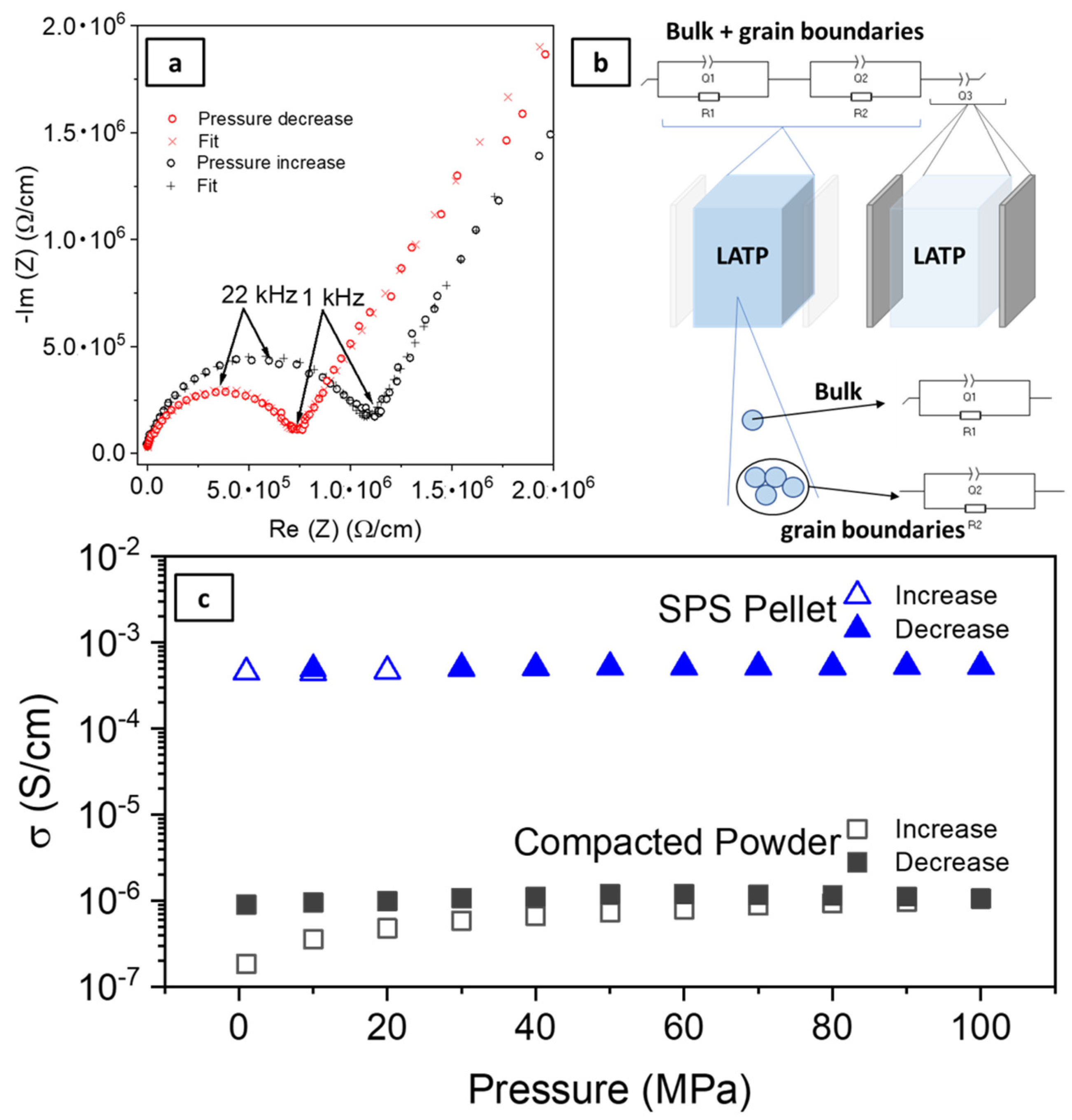
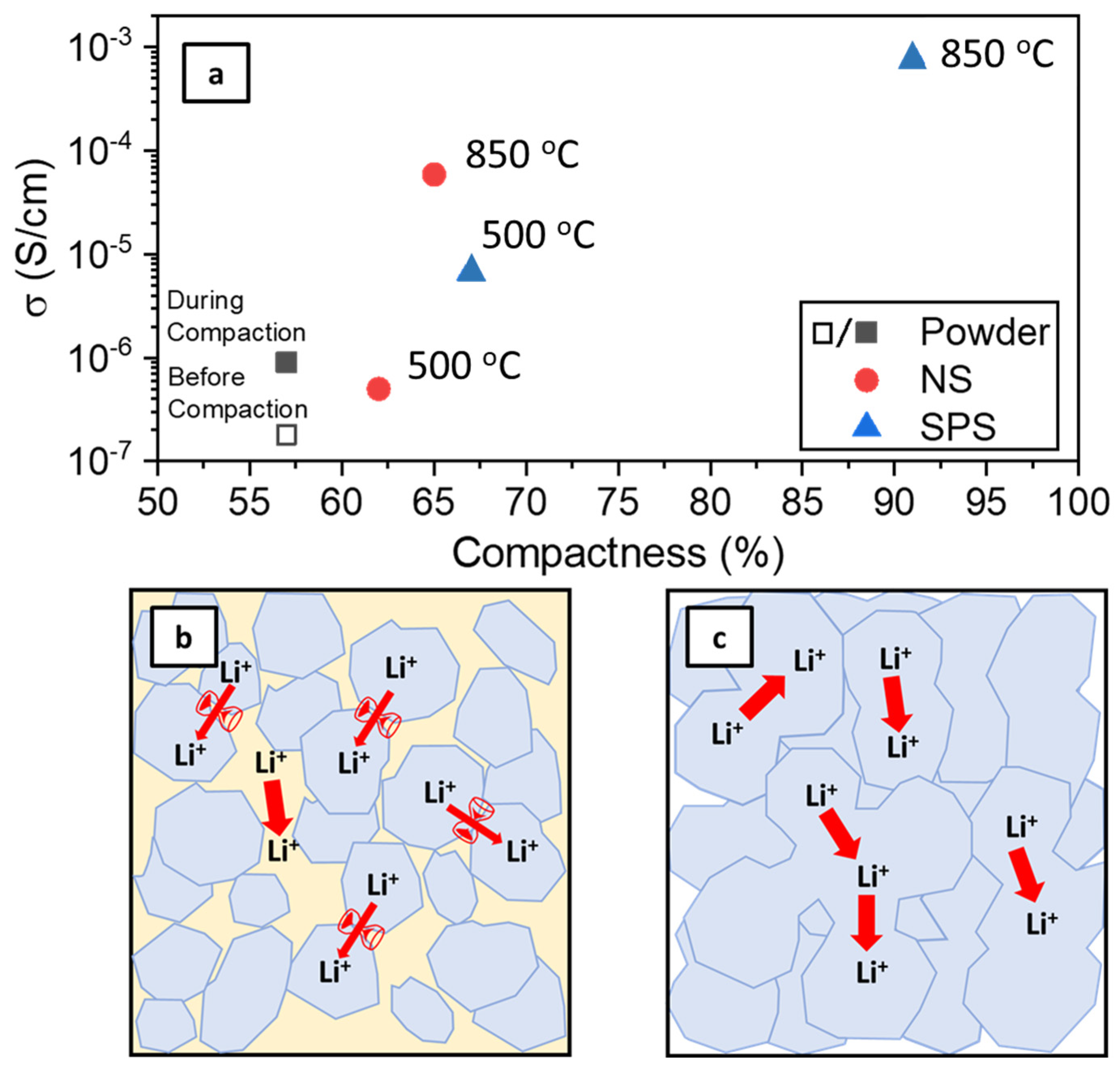
EIS measurements were conducted in a symmetrical SS/ISE/SS or SS/SCE/SS configuration (SS = Stainless Steel). The data was recorded using a Biologic SP 150 potentiostat between 1 MHz and 100 mHz. A large voltage amplitude of 100 mV was chosen such that a clear current response could be obtained while retaining a linear relationship between current and voltage. The bulk conductivity of the LATP SPS pellet was measured using a Biologic SP 300 at frequencies ranging from 7 MHz to 100 mHz.
All EIS measurements were performed using a home-made pressure device (diameter of 12 mm). Pressure was increased from 1 MPa to 100 MPa in steps of 10 MPa, followed by a sequence of measurements from 100 MPa to 1 MPa in order to evaluate the impact of an external pressure on the ionic conductivity. All measurements were made inside a glovebox to avoid air contamination. Triplicate measurements were performed to ensure reproducibility.
The ionic conductivity (S/cm) was calculated using the equation
σ = L/(R · S)
where L is the thickness of the SSE (cm), R is the overall resistance (Ω), and S is the area of the SSE (cm2).

3. Results

The aim of this paper is to investigate the impact of LATP processing on its conductive properties when used as a CE or SCE for ASSLB applications. Particularly, the effect of applied pressure on the ionic conductivity of compacted powder and a polymer/ceramic composite was studied. This study was motivated by concerns that applied pressure (during the material fabrication process as well as during measurement/cycling) appears to be a key parameter in the optimization of ceramic electrolytes in particular, and ASSLBs in general [4,5,35].
The LATP powder used in this study consists of ca. 10 µm particles, as shown in Figure S1, and the powder presents a XRD pattern (Figure S2) corresponding to the R-3c Rhombohedral space group. This corresponds to the LATP ICSD file #00-066-0872. A low-intensity peak observed at 21.9° corresponds to an AlPO4 impurity which can be seen in Figure S2. After SPS at 850 °C, the crystal structure of the material remains unchanged.
Figure 1a shows examples of Nyquist plots obtained by electrochemical impedance spectroscopy for compacted LATP particles. The spectra were collected at a pressure of 60 MPa. The corresponding fit derived from the equivalent circuit model is also shown (Figure 1b). In the case of ceramic materials, bulk (σb) and grain boundary (σGB) contributions are expected to be present in the Nyquist plots. For a dense LATP pellet, like the one shown in Figure S3, both contributions are quite close. The EIS diagram of the LATP SPS (850 °C) pellet, starting from 7 MHz, is shown in Figure S4, to demonstrate both contributions to the total conductivity. The contribution from the bulk is visible up to ca. 620 Ω/cm, whereas the contribution from the grain boundaries appears at lower frequencies, up to 5 kΩ/cm. The slanting line at low frequencies is associated with charge accumulation at the blocking electrode surfaces that is ascribed by a Constant Phase Element Q3 in the equivalent circuit in Figure 2b. For compacted LATP powder, the bulk contribution is not visible in the figure due to scaling. As a result, only one depressed semi-circle is observed over the whole frequency range. This semi-circle mostly corresponds to the “grain-boundary” contribution (Figure 1b). Applied pressure was found to impact the total resistance of the compacted powders (Figure 1a). For instance, when the EIS is measured at 60 MPa during the increase in pressure from 1 to 100 MPa (red dots) or during the decrease in pressure from 100 MPa to 1 MPa (black dots), the shape of the signal remains very similar. However, the overall resistance changes. The action of compacting LATP powder particles (with increased pressure) has a non-negligible impact. This can be explained by the compaction of the powder. Upon pressure increase, the powder particles adapt to the pressure in their most favorable configuration, while that configuration is kept upon pressure release. This contrasts sharply with that of the SPS pellet, where applied pressure does not impact the measured resistance.
To confirm the effect of the external pressure on the samples, i.e., the compaction of ceramic particles, the evolution of the total ionic conductivities of the LATP powders and an SPS pellet as a function of applied pressure is reported in Figure 1c. It is worth noting that SPS results in considerable improvement of the total ionic conductivity compared to compacted LATP powder. This point will be addressed later in the discussion. For the sintered samples, the same total ionic conductivity (above 5 × 10⁻⁴ S/cm) is observed independently of the pressure applied during EIS measurements. However, for the compacted LATP powders, the total ionic conductivity increases from 1.8 × 10⁻⁷ S/cm to 1.1 × 10⁻⁶ S/cm when pressure is increased from 1 MPa to 100 MPa. Ionic conductivity remains stable as the pressure is decreased. These values agree with those found for the non-sintered material [36]. This response can be contrasted to that of the powder samples, as the ionic conductivities of the compacted powder are still nearly three orders of magnitude lower than that of the sintered one.

3.1. Evaluating the Benefit of Sintering

The sintering process results in the compacting and welding of solid particles with the help of temperature and/or pressure below the melting point. The main benefits are the enhancement of the mechanical strength and the conductivity of the material via the densification of the pristine powder material. In this part of the study, the impact of the sintering parameters on the ionic conductivity of LATP is discussed.
Two sintering methods were used to achieve high-quality LATP pellets: natural sintering (NS) and Spark plasma sintering (SPS). The SPS technique is a specific sintering process that rapidly produces dense ceramic pellets via the assistance of uniaxial pressure and a pulsed electric current. Consequently, this process improves grain cohesion by welding them together, thus limiting the grain boundary contribution to the overall conductivity [6,12,37,38]. Moreover, while the NS procedure takes several hours to complete, the SPS process can be performed in less than one hour. The study of the impact of the sintering temperature on ionic conductivities for both NS and SPS methods was conducted. The total ionic conductivities of the sintered samples were compared to the as-synthesized LATP powders. Figure 2a displays the evolution of the total ionic conductivity as a function of geometric compactness for LATP ceramic samples prepared via three different methods at 30 °C (as-synthesized powders, NS, and SPS pellets). According to Figure S4, the bulk contribution to the total conductivity accounts for 3 × 10⁻³ S/cm. The bulk contribution is assumed to be the same for all samples, since they were prepared from the same powder. Lower total conductivity, observed in Figure 2a, is then due to grain boundary and inter-particles conduction processes. Still, similar activation energies of 0.48 ± 0.05 eV are found independent of the shaping process, as can be seen in Figure S5. In the present case, as LATP is a nanocrystalline material with high porosity, surface diffusion can also occur and influence the activation energy in addition to bulk and interface diffusion [38]. However, this was not observed here. This may indicate that the conductivity decrease is instead related to a tortuosity–porosity effect as well as the presence of disconnected or partially connected structures hindering efficient ionic diffusion [13,39,40,41]. This results in a reduced effective diffusion, Deff, in porous media, compared to the bulk diffusion, Dbulk, which is tempered by a constriction coefficient δ due to the pore diameter and tortuosity, τd. Such effective diffusion directly impacts the diffusive flux according to Fick’s law [38]. Several models and approaches for determining the porosity–tortuosity relationship have been defined and provide variable results [42]. Imaging techniques, such as X-ray Microtomography assisted by numerical simulation, could help unravel the pore distribution and structure within the pellets or powder and define a reliable Representative Elementary Volume (REV) depending on the sample preparation method [13,42,43,44]. Except for the LATP SPS (850 °C) sample (91% of compactness as shown in Figure S3), all pellets have a compactness in the range of 57 to 67% no matter what processing method is used. With the exception of the NS sample with lowest compactness, it is worth noting that the ionic conductivities of the sintered LATP pellets are systematically superior to that of the LATP powder, regardless of whether it is compacted or not. However, among the sintered LATP samples, a large range of ionic conductivities is reported. These were found to depend on the compactness and the sintering process (NS vs. SPS) used in the preparation of the sample. The conductivity of the SPS LATP (850 °C) is 7.6 × 10⁻⁴ S/cm due to the high compactness of the sample. For compactness in close range of 57 to 67%, though, the impact of processing temperature driving particle sintering led to increasing total conductivities. Still, such low compactness causes a conductivity penalty of several orders of magnitude compared to the 91% compact sample, while the ionic conductivity of the NS sintered LATP is 5.9 × 10⁻⁵ S/cm at the same temperature. Low processing temperatures do not, in fact, allow for efficient grain growth and coalescence. For instance, 500 °C was found to be too low to achieve good sintering (Figure S6). These observations hold true independently of the sintering process used and its duration. Even SPS processing at high pressures does not result in improved conductivity when the sintering temperature is too low. Figure 2b,c propose a schematic representation of the pellet microstructures that are produced by low- and high-temperature sintering processes, respectively. Tortuosity and porosity are often evoked to explain transport phenomena and diffusion paths [39,40,42,43,44]. Contact between grains is limited to single-point particle-to-particle contact in powders that were directly pressed and processed at low temperatures. In this system, constriction between pore necks and pore structures act as bottlenecks that limit ionic transfer [13,41]. Lithium conductivity is improved in dense sintered ceramic pellets. This is due to improved contacts between grains and large conduction domains resulting from the sintering and welding of the powder particles. This behavior is exacerbated by the SPS method, which improves the overall ionic conductivity of the LATP samples. These results confirm that both high temperature and pressure loading, such as that for SPS processing, are needed to produce highly conductive LATP solid electrolytes.

3.2. LATP/PEO Solid Composite Electrolyte

In order to extend the scope of the study, ionic conductivity in a SCE comprised of LATP particles and a polymer electrolyte was studied. SCE are generally prepared by dispersing inorganic fillers in the polymer matrix. The fillers can be inert (SiO2, BaTiO3, TiO2) or active (ceramics like LATP, LAGP, LLZO) [15,45]. Relative to SPE or CE, SCE generally have improved properties such as: enhanced interfacial stability/compatibility with electrode materials, ionic conductivity (caused by decreasing the crystallinity of the polymer host) and mechanical properties. In order to investigate this perspective, SCE were prepared by directly mixing the LATP ceramic powder and polymer together as generally reported in the literature [18,46,47,48]. Polyethylene oxide (PEO) containing LiTFSI salt was chosen as the polymer matrix as it is recognized as a benchmark SPE. SCE were prepared through an easy and reproducible solvent-assisted (acetonitrile) method [38]. The incorporation of ceramic (i.e., LATP) within a polymer matrix is expected to improve ionic conductivity [49,50,51]. Different amounts of ceramic were used with the aim of finding an optimized configuration. Three solid composite electrolytes (SCE) were prepared, PEO-LATP25 (containing 25 wt.% LATP representing ≈ 12 vol.% LATP), PEO-LATP75 (containing 75 wt.% LATP; 56 vol.% LATP) and PEO-LATP85 (containing 85 wt.% LATP; 70 vol.% LATP).
Owing to energy density consideration, the compositions of the composite materials were chosen so that their density, [1.4; 2.4] g/cm3, are in close range with that of sintered ceramic pellets under investigation in the manuscript [1.7; 2.7] g/cm3. A pure PEO solid electrolyte and a PEO-LATP75 sample without LiTFSI salt were also synthesized for comparison. Increased ceramic loading in the SCEs can be observed by SEM imaging (Figure 3a). Homogeneous dispersions of ceramic are visible in a large area of polymer.
EIS measurements were performed on the whole series of samples. Typical EIS diagrams corresponding to PEO-LiTFSI and PEO-LATP85 are displayed in Figure 3b,c. For PEO-LiTFSI (Figure 3b), a typical single half circle is observed. The diagrams of SCE, PEO-LATP85 (Figure 3c) are largely depleted and clearly present several contributions contrasting with that of the SPE or pure LATP compressed powder of Figure 1a. The shape of the signal is the same independently of the applied pressure. The contributions of both polymer phase and ceramic point contact can indeed be expected. However, the depleted character of the diagram does not allow fitting using simple RC circuit in series. Extra contribution at medium frequencies originating from the interface between the SPE and ceramic particle cannot be ruled out completely [27]. Owing to the characteristic frequencies, the first contribution at 65 kHz can be ascribed to the polymeric part when the second at 4 kHz to the SPE/ceramic interface. This ionic mobility phenomenon at this frequency cannot be related to the bulk part nor grain boundaries of the sintered ceramic. These are expected to occur at much higher frequencies according to Figure S4. Nevertheless, the frequency is closer to that corresponding to point contact of ceramic particles as determined in Figure 1a. It is also important to mention that a sample PEO-LATP without LiTFSI salt was too insulating (lower than 10−11 S/cm) for ionic conductivity to be accurately measured by EIS (Figure S8). In the conditions of our study, even the contribution of the ceramic (bulk and point-contact) is not visible despite the application of pressure to ensure contact percolation between the ceramic particles. This underlines the need for a conducting polymer and the fact that ionic transport in the SCE mainly occurs through the polymer electrolyte [22,36,52]. Ionic transport between conducting ceramic particles is not possible when these are disconnected by an insulating polymer, such as salt-free PEO or PVDF. Such phenomenon was first conceptualized in porous media by Bellini et al. via a zero-connectivity situation and infinite tortuosity above a Limit Porosity Value [39]. Figure 3d. displays the evolution of the ionic conductivity of PEO-LATP composite electrolytes compared to that of PEO SPE when the applied pressure is decreased at room temperature. The results show that the ionic conductivity range of the SCEs is similar to the ionic conductivity of pure PEO regardless of the percentage of LATP in the PEO host. Still, the resulting ionic conductivities range for SCE between 1.2 × 10⁻⁶ S/cm and 4.1 × 10⁻⁶ S/cm at low and moderate pressures (up to 50 MPa). Overall, a slight decrease of ionic conductivity with pressure is observed for the PEO-based SCE and SPE. This agrees with Stoeva et al. for measurements performed below the melting temperature of the polymer [53]. This can be explained by large activation volumes and energies due to the size of the moving anions and reduced segmental motions of the polymer backbone. For PEO-LATP85 though, the conductivity remains stable regardless of the applied pressure although it remains below 10−5 S/cm. The reason for such discrepancy is not clear yet. It is likely that the large amount of LATP content may counteract the pressure impact and allow the presence of polymer zones without reduced segmental motion or thanks to an interaction between polymer host and ceramic particles as could be evidenced by an extra contribution at low frequencies.
At 70 °C, the EIS diagram of PEO-LiTFSI does not allow any fitting as no half circle is observed in Figure 3e due to the high conductivity of the SPE. For very high ceramic loading though in Figure 3f, a clear depressed half-circle is visible. The zero shift at high frequencies is related to the polymer contribution. The contribution at mid-frequencies could be ascribed to point-contact of ceramic particles. The frequencies, however, are much higher (120 kHz) compared to that found for compact powder at the same temperature in Figure S7 and fall closer to the frequency range for grain boundaries in sintered LATP. Another likely possibility is the SPE/ceramic interface contribution. Overlapping of the frequencies between the grain boundaries and/or the SPE/ceramic interface cannot be excluded at this point. Figure 3g. presents the total ionic conductivities at 70 °C for all composite electrolytes upon decrease of pressure. For 100% SPE and composite with lower ceramic amount, the conductivity is stable and much similar at 10−3 S/cm independently of the pressure. For PEO-LATP85 composite, the conductivities are slightly decreasing but more importantly reach a conductivity ten-fold lower than the other composites or pure SPE. Eventually, this tends to demonstrate that a high ceramic loading is not beneficial as it may not only increase the tortuosity within the media but also disrupt the polymer conduction path. Above a certain threshold of the ceramic phase in such two-phase mixture, disruption of the conduction path is indeed likely to occur as was reported by Roman et al. [54]. Even if both phases are ion conducting, hopping of the ion from one phase to the other is not guaranteed [22]. Upon application of pressure, accentuation of the disruption of the polymer continuous conduction paths is even more likely to occur, consequently the overall conductivity tends to decrease with increase of pressure. In that sense, X-ray Tomography could be a valuable technique to evaluate the distribution of one phase compared to the other.
Overall, no significant increase of conductivity is observed with use of a composite electrolyte, consisting of dispersed ceramic particles within a polymeric matrix, in comparison to pristine SPE independently of ceramic concentration. Only a few previous works that discuss conductive ceramic and inert fillers state that the incorporation of ceramics does not improve the ionic conductivity of the SCE [55,56,57,58,59]. Nevertheless, these results contrast with the general trend, where the addition of ceramics results in improved ionic conductivity [20,21,48,50,51,60,61]. This highlights the necessity of in depth understanding the ionic transfer between the SPE and the ceramic particles in agreement with recently reported data [22]. However, it must be kept in mind that the variety and complexity of experimental procedures and measurements can lead to significant variation in results. More generally, the battery community lacks standardized testing procedures for making impartial comparisons [62,63,64]. For instance, ceramic clusters may prevent the maximum ceramic surface area to volume ratio necessary for statistic percolation and ideal polymer/particle interaction from being reached [20]. The current results show that ceramic sintering with SPS at high temperature results in dense, high quality LATP ceramics with high ionic conductivity at ambient temperature. This does not seem to be possible when using dispersed ceramic powder particles in a polymer matrix. Whether it be for LATP powders or LATP powder dispersed inside the PEO polymer electrolyte, ceramic particle to particle point contacts alone cannot achieve the required room temperature ionic conductivity. This also demonstrates the need of creating a continuous conduction network in hybrid electrolytes, this will require to work on the ceramic-polymer interface to allow easy ion transfer between them without bottleneck [22,65,66].

4. Conclusions

In this study, the ionic conductivity of LATP materials produced using different processing methods (NS, SPS, and as powder) was evaluated at room temperature. The contribution of point contacts between particles to the ionic conductivity of compacted powders and sintered pellets is extracted and discussed. Considerable decreases in conductivity are observed in compacted loose powders when compared to well-sintered pellets. This is caused by conduction bottlenecks between particles. On this basis, SCEs containing different amounts of LATP particles dispersed in PEO polymer hosts were prepared. Their ionic conductivities were evaluated over a large range of pressure to determine ideal ionic percolation. The benefit of the inclusion of ceramic particles in polymeric hosts was found to be limited.
This study, therefore, contradicts common consensus on SCEs, as it shows that ionic conductivity occurs through the polymer alone. Taking full advantage of the high conductivity of bulk ceramics requires sintering to yield a dense ceramic domain. As ceramic sintering, from the point of view of time and material thermomechanical compatibility [22], might be a limiting step in industrial battery applications, alternative composite solutions allowing a continuous conduction network should be sought without impacting the cell energy density, while minimizing the interfacial resistive contribution.

Supplementary Materials

The following supporting information can be downloaded at: https://www.mdpi.com/article/10.3390/batteries9020087/s1, Figure S1: SEM pictures of the LATP powder used throughout the study; Figure S2: XRD pattern of the LATP powder synthesized for this study; Figure S3: SEM picture of the cross section of the LATP SPS pellet sintered at 850 °C; Figure S4: EIS Diagram at room temperature of the LATP pellet produced by SPS at 850 °C; Figure S5: EIS Diagram of LATP pellets produced by SPS and NS at 850 °C and 500 °C; Figure S6: SEM picture of the cross section of the LATP NS pellet prepared at 500 °C; Figure S7: EIS diagrams at 20 MPa upon decrease of applied pressure for LATP at 70 °C for compact powder (a) and pellet produced by SPS at 850 °C (b); Figure S8: EIS diagrams at RT at 20 MPa upon decrease of applied pressure for PEO-LATP75 without LITFSI Salt.

Author Contributions

Conceptualization, A.M., S.R., D.L. and M.D.; methodology, A.M.; formal analysis, A.M., S.R. and D.L.; data curation, A.M., S.R. and D.L.; writing—original draft preparation, A.M.; writing—review and editing, A.M., S.R, D.L. and M.D.; supervision, M.D.; project administration, M.D. and D.A.-P.; funding acquisition, M.D. and D.A.-P. All authors have read and agreed to the published version of the manuscript.

Funding

This research was funded by the Natural Sciences and Engineering Research Council of Canada (NSERC RDCPJ 528052-18) and TotalEnergies.

Institutional Review Board Statement

Not applicable.

Informed Consent Statement

Not applicable.

Data Availability Statement

Not applicable.

Acknowledgments

The authors gratefully acknowledge the financial support received from the Natural Sciences and Engineering Research Council of Canada (NSERC RDCPJ 528052-18) and TotalEnergies. The author wish to thank Gabrielle Foran for her help with editing the present manuscript.

Conflicts of Interest

The authors declare no conflict of interest.

References

  1. Duffner, F.; Kronemeyer, N.; Tübke, J.; Leker, J.; Winter, M.; Schmuch, R. Post-lithium-ion battery cell production and its compatibility with lithium-ion cell production infrastructure. Nat. Energy 2021, 6, 123–134. [Google Scholar] [CrossRef]
  2. Zheng, F.; Kotobuki, M.; Song, S.; Lai, M.O.; Lu, L. Review on solid electrolytes for all-solid-state lithium-ion batteries. J. Power Sources 2018, 389, 198–213. [Google Scholar] [CrossRef]
  3. Chen, L.; Huang, Y.-F.; Ma, J.; Ling, H.; Kang, F.; He, Y.-B. Progress and Perspective of All-Solid-State Lithium Batteries with High Performance at Room Temperature. Energy Fuels 2020, 34, 13456–13472. [Google Scholar] [CrossRef]
  4. Doux, J.-M.; Nguyen, H.; Tan, D.H.S.; Banerjee, A.; Wang, X.; Wu, E.A.; Jo, C.; Yang, H.; Meng, Y.S. Stack Pressure Considerations for Room-Temperature All-Solid-State Lithium Metal Batteries. Adv. Energy Mater. 2020, 10, 1903253. [Google Scholar] [CrossRef] [Green Version]
  5. Doux, J.-M.; Yang, Y.; Tan, D.H.S.; Nguyen, H.; Wu, E.A.; Wang, X.; Banerjee, A.; Meng, Y.S. Pressure effects on sulfide electrolytes for all solid-state batteries. J. Mater. Chem. A 2020, 8, 5049–5055. [Google Scholar]
  6. Benabed, Y.; Rioux, M.; Rousselot, S.; Hautier, G.; Dollé, M. Assessing the Electrochemical Stability Window of NASICON-Type Solid Electrolytes. Front. Energy Res. 2021, 9, 682008. [Google Scholar] [CrossRef]
  7. Schell, K.G.; Bucharsky, E.C.; Lemke, F.; Hoffmann, M.J. Effect of calcination conditions on lithium conductivity in Li1.3Ti1.7Al0.3(PO4)3 prepared by sol-gel route. Ionics 2017, 23, 821–827. [Google Scholar] [CrossRef]
  8. Yan, G.; Yu, S.; Nonemacher, J.F.; Tempel, H.; Kungl, H.; Malzbender, J.; Eichel, R.-A.; Krüger, M. Influence of sintering temperature on conductivity and mechanical behavior of the solid electrolyte LATP. Ceram. Int. 2019, 45, 14697–14703. [Google Scholar] [CrossRef]
  9. Chaim, R.; Levin, M.; Shlayer, A.; Estournes, C. Sintering and densification of nanocrystalline ceramic oxide powders: A review. Adv. Appl. Ceram. 2008, 107, 159–169. [Google Scholar] [CrossRef] [Green Version]
  10. Delaizir, G.; Dollé, M.; Rozier, P.; Zhang, X.H. Spark Plasma Sintering: An Easy Way to Make Infrared Transparent Glass-Ceramics. J. Am. Ceram. Soc. 2010, 93, 2495–2498. [Google Scholar] [CrossRef]
  11. Xu, X.; Wen, Z.; Yang, X.; Chen, L. Dense nanostructured solid electrolyte with high Li-ion conductivity by spark plasma sintering technique. Mater. Res. Bull. 2008, 43, 2334–2341. [Google Scholar] [CrossRef]
  12. Yamada, H.; Ito, T.; Basappa, R.H. Sintering Mechanisms of High-Performance Garnet-type Solid Electrolyte Densified by Spark Plasma Sintering. Electrochim. Acta 2016, 222, 648–656. [Google Scholar] [CrossRef] [Green Version]
  13. Dixit, M.B.; Regala, M.; Shen, F.; Xiao, X.; Hatzell, K.B. Tortuosity Effects in Garnet-Type Li7La3Zr2O12 Solid Electrolytes. ACS Appl. Mater. Interfaces 2019, 11, 2022–2030. [Google Scholar] [CrossRef]
  14. Waetzig, K.; Rost, A.; Heubner, C.; Coeler, M.; Nikolowski, K.; Wolter, M.; Schilm, J. Synthesis and sintering of Li1.3Al0.3Ti1.7(PO4)3 (LATP) electrolyte for ceramics with improved Li+ conductivity. J. Alloys Compd. 2020, 818, 153237. [Google Scholar] [CrossRef]
  15. Tang, S.; Guo, W.; Fu, Y. Advances in Composite Polymer Electrolytes for Lithium Batteries and Beyond. Adv. Energy Mater. 2021, 11, 2000802. [Google Scholar] [CrossRef]
  16. Yao, P.; Yu, H.; Ding, Z.; Liu, Y.; Lu, J.; Lavorgna, M.; Wu, J.; Liu, X. Review on Polymer-Based Composite Electrolytes for Lithium Batteries. Front. Chem. 2019, 7, 522. [Google Scholar] [CrossRef] [Green Version]
  17. Chen, L.; Li, Y.; Li, S.-P.; Fan, L.-Z.; Nan, C.-W.; Goodenough, J.B. PEO/garnet composite electrolytes for solid-state lithium batteries: From “ceramic-in-polymer” to “polymer-in-ceramic”. Nano Energy 2018, 46, 176–184. [Google Scholar] [CrossRef]
  18. Ban, X.Y.; Zhang, W.Q.; Chen, N.; Sun, C.W. A High-Performance and Durable Poly(ethylene oxide)-Based Composite Solid Electrolyte for All Solid-State Lithium Battery. J. Phys. Chem. C 2018, 122, 9852–9858. [Google Scholar] [CrossRef]
  19. Yu, X.; Manthiram, A. A Long Cycle Life, All-Solid-State Lithium Battery with a Ceramic–Polymer Composite Electrolyte. ACS Appl. Energy Mater. 2020, 3, 2916–2924. [Google Scholar] [CrossRef]
  20. Zaman, W.; Hortance, N.; Dixit, M.B.; De Andrade, V.; Hatzell, K.B. Visualizing percolation and ion transport in hybrid solid electrolytes for Li–metal batteries. J. Mater. Chem. A 2019, 7, 23914–23921. [Google Scholar] [CrossRef]
  21. Song, X.; Zhang, H.; Jiang, D.; Yang, L.; Zhang, J.; Yao, M.; Ji, X.; Wang, G.; Zhang, S. Enhanced transport and favorable distribution of Li-ion in a poly(ionic liquid) based electrolyte facilitated by Li1.3Al0.3Ti1.7(PO4)3 nanoparticles for highly-safe lithium metal batteries. Electrochim. Acta 2021, 368, 137581. [Google Scholar] [CrossRef]
  22. Foran, G.; Mery, A.; Bertrand, M.; Rousselot, S.; Lepage, D.; Aymé-Perrot, D.; Dollé, M. NMR Study of Lithium Transport in Liquid–Ceramic Hybrid Solid Composite Electrolytes. ACS Appl. Mater. Interfaces 2022, 14, 43226–43236. [Google Scholar] [CrossRef] [PubMed]
  23. Isaac, J.A.; Devaux, D.; Bouchet, R. Dense inorganic electrolyte particles as a lever to promote composite electrolyte conductivity. Nat. Mater. 2022, 21, 1412–1418. [Google Scholar] [PubMed]
  24. Paolella, A.; Bertoni, G.; Zhu, W.; Campanella, D.; La Monaca, A.; Girard, G.; Demers, H.; Gheorghe Nita, A.C.; Feng, Z.; Vijh, A.; et al. Unveiling the Cation Exchange Reaction between the NASICON Li1.5Al0.5Ge1.5(PO4)3 Solid Electrolyte and the pyr13TFSI Ionic Liquid. J. Am. Chem. Soc. 2022, 144, 3442–3448. [Google Scholar] [CrossRef] [PubMed]
  25. Chen, R.; Li, Q.; Yu, X.; Chen, L.; Li, H. Approaching Practically Accessible Solid-State Batteries: Stability Issues Related to Solid Electrolytes and Interfaces. Chem. Rev. 2019, 120, 6820–6877. [Google Scholar] [CrossRef] [PubMed]
  26. Gupta, A.; Sakamoto, J. Controlling Ionic Transport through the PEO-LiTFSI/LLZTO Interface. Electrochem. Soc. Interface 2019, 28, 63. [Google Scholar]
  27. Isaac, J.A.; Mangani, L.R.; Devaux, D.; Bouchet, R. Electrochemical Impedance Spectroscopy of PEO-LATP Model Multilayers: Ionic Charge Transport and Transfer. ACS Appl. Mater. Interfaces 2022, 14, 13158–13168. [Google Scholar] [CrossRef] [PubMed]
  28. Bertrand, M.; Rousselot, S.; Aymé-Perrot, D.; Dollé, M. Compatibility assessment of solid ceramic electrolytes and active materials based on thermal dilatation for the development of solid-state batteries. Mater. Adv. 2021, 2, 2989–2999. [Google Scholar] [CrossRef]
  29. Miara, L.; Windmüller, A.; Tsai, C.-L.; Richards, W.D.; Ma, Q.; Uhlenbruck, S.; Guillon, O.; Ceder, G. About the Compatibility between High Voltage Spinel Cathode Materials and Solid Oxide Electrolytes as a Function of Temperature. ACS Appl. Mater. Interfaces 2016, 8, 26842–26850. [Google Scholar] [CrossRef] [Green Version]
  30. Yu, C.-Y.; Choi, J.; Anandan, V.; Kim, J.-H. High-Temperature Chemical Stability of Li1.4Al0.4Ti1.6(PO4)3 Solid Electrolyte with Various Cathode Materials for Solid-State Batteries. J. Phys. Chem. C 2020, 124, 14963–14971. [Google Scholar] [CrossRef]
  31. Wei, X.; Rechtin, J.; Olevsky, E.A. The Fabrication of All-Solid-State Lithium-Ion Batteries via Spark Plasma Sintering. Metals 2017, 7, 372. [Google Scholar] [CrossRef]
  32. Lascaud, S.; Perrier, M.; Vallee, A.; Besner, S.; Prud’homme, J.; Armand, M. Phase Diagrams and Conductivity Behavior of Poly(ethylene oxide)-Molten Salt Rubbery Electrolytes. Macromolecules 1994, 27, 7469–7477. [Google Scholar] [CrossRef]
  33. Foran, G.; Mankovsky, D.; Verdier, N.; Lepage, D.; Prébé, A.; Aymé-Perrot, D.; Dollé, M. The Impact of Absorbed Solvent on the Performance of Solid Polymer Electrolytes for Use in Solid-State Lithium Batteries. Iscience 2020, 23, 101597. [Google Scholar] [CrossRef] [PubMed]
  34. Mankovsky, D.; Lepage, D.; Lachal, M.; Caradant, L.; Aymé-Perrot, D.; Dollé, M. Water content in solid polymer electrolytes: The lost knowledge. Chem. Commun. 2020, 56, 10167–10170. [Google Scholar] [CrossRef]
  35. Famprikis, T.; Kudu, Ö.U.; Dawson, J.A.; Canepa, P.; Fauth, F.; Suard, E.; Zbiri, M.; Dambournet, D.; Borkiewicz, O.J.; Bouyanfif, H.; et al. Under Pressure: Mechanochemical Effects on Structure and Ion Conduction in the Sodium-Ion Solid Electrolyte Na3PS4. J. Am. Chem. Soc. 2020, 142, 18422–18436. [Google Scholar] [CrossRef]
  36. Bonizzoni, S.; Ferrara, C.; Berbenni, V.; Anselmi-Tamburini, U.; Mustarelli, P.; Tealdi, C. NASICON-type polymer-in-ceramic composite electrolytes for lithium batteries. Phys. Chem. Chem. Phys. 2019, 21, 6142–6149. [Google Scholar] [CrossRef]
  37. Dumont-Botto, E.; Bourbon, C.; Patoux, S.; Rozier, P.; Dolle, M. Synthesis by Spark Plasma Sintering: A new way to obtain electrode materials for lithium ion batteries. J. Power Sources 2011, 196, 2274–2278. [Google Scholar] [CrossRef]
  38. Heitjans, P.; Indris, S. Diffusion and ionic conduction in nanocrystalline ceramics. J. Physics Condens. Matter 2003, 15, R1257–R1289. [Google Scholar] [CrossRef]
  39. Bellini, S.; Azzato, G.; Grandinetti, M.; Stellato, V.; De Marco, G.; Sun, Y.; Caravella, A. A Novel Connectivity Factor for Morphological Characterization of Membranes and Porous Media: A Simulation Study on Structures of Mono-Sized Spherical Particles. Appl. Sci. 2018, 8, 573. [Google Scholar] [CrossRef] [Green Version]
  40. Caravella, A.; Bellini, S.; Azzato, G.; De Marco, G.; Sun, Y. 4-Tortuosity evaluation for characterization of transport phenomena in pure-crystalline metal lattices and porous media. In Current Trends and Future Developments on (Bio-) Membranes; Basile, A., Gallucci, F., Eds.; Elsevier: Amsterdam, The Netherlands, 2020; pp. 91–122. [Google Scholar]
  41. Wiedenmann, D.; Keller, L.; Holzer, L.; Stojadinović, J.; Münch, B.; Suarez, L.; Fumey, B.; Hagendorfer, H.; Brönnimann, R.; Modregger, P.; et al. Three-dimensional pore structure and ion conductivity of porous ceramic diaphragms. AIChE J. 2013, 59, 1446–1457. [Google Scholar] [CrossRef] [Green Version]
  42. Tjaden, B.; Brett, D.J.L.; Shearing, P.R. Tortuosity in electrochemical devices: A review of calculation approaches. Int. Mater. Rev. 2018, 63, 47–67. [Google Scholar] [CrossRef] [Green Version]
  43. Sun, Z.; Tang, X.; Cheng, G. Numerical simulation for tortuosity of porous media. Microporous Mesoporous Mater. 2013, 173, 37–42. [Google Scholar] [CrossRef]
  44. Tjaden, B.; Lane, J.; Withers, P.J.; Bradley, R.S.; Brett, D.J.L.; Shearing, P.R. The application of 3D imaging techniques, simulation and diffusion experiments to explore transport properties in porous oxygen transport membrane support materials. Solid State Ionics 2016, 288, 315–321. [Google Scholar] [CrossRef]
  45. Zhang, D.; Xu, X.; Qin, Y.; Ji, S.; Huo, Y.; Wang, Z.; Liu, Z.; Shen, J.; Liu, J. Recent Progress in Organic–Inorganic Composite Solid Electrolytes for All-Solid-State Lithium Batteries. Chem. Eur. J. 2020, 26, 1720–1736. [Google Scholar] [CrossRef]
  46. Siyal, S.H.; Li, M.; Li, H.; Lan, J.-L.; Yu, Y.; Yang, X. Ultraviolet irradiated PEO/LATP composite gel polymer electrolytes for lithium-metallic batteries (LMBs). Appl. Surf. Sci. 2019, 494, 1119–1126. [Google Scholar] [CrossRef]
  47. Yu, X.; Li, J.; Manthiram, A. Rational Design of a Laminated Dual-Polymer/Polymer–Ceramic Composite Electrolyte for High-Voltage All-Solid-State Lithium Batteries. ACS Mater. Lett. 2020, 2, 317–324. [Google Scholar] [CrossRef]
  48. Yu, X.; Manthiram, A. Electrode–Electrolyte Interfaces in Lithium–Sulfur Batteries with Liquid or Inorganic Solid Electrolytes. Acc. Chem. Res. 2017, 50, 2653–2660. [Google Scholar] [CrossRef]
  49. Liu, K.; Liu, Y.Y.; Lin, D.C.; Pei, A.; Cui, Y. Materials for lithium-ion battery safety. Sci. Adv. 2018, 4, eaas9820. [Google Scholar] [CrossRef] [Green Version]
  50. Liu, L.; Chu, L.; Jiang, B.; Li, M. Li1.4Al0.4Ti1.6(PO4)3 nanoparticle-reinforced solid polymer electrolytes for all-solid-state lithium batteries. Solid State Ionics 2019, 331, 89–95. [Google Scholar] [CrossRef]
  51. Pan, K.; Zhang, L.; Qian, W.; Wu, X.; Dong, K.; Zhang, H.; Zhang, S. Flexible Ceramic/Polymer Hybrid Solid Electrolyte for Solid-State Lithium Metal Batteries. Adv. Mater. 2020, 32, e2000399. [Google Scholar] [CrossRef]
  52. Guo, J.; Berbano, S.S.; Guo, H.; Baker, A.L.; Lanagan, M.T.; Randall, C.A. Cold Sintering Process of Composites: Bridging the Processing Temperature Gap of Ceramic and Polymer Materials. Adv. Funct. Mater. 2016, 26, 7115–7121. [Google Scholar] [CrossRef]
  53. Stoeva, Z.; Imrie, C.T.; Ingram, M.D. Effect of pressure on ion transport in amorphous and semi-crystalline polymer electrolytes. Phys. Chem. Chem. Phys. 2003, 5, 395–399. [Google Scholar]
  54. Roman, H.E.; Bunde, A.; Dieterich, W. Conductivity of dispersed ionic conductors: A percolation model with two critical points. Phys. Rev. B 1986, 34, 3439–3445. [Google Scholar] [CrossRef]
  55. Choi, B.-K.; Kim, Y.-W.; Shin, K.-H. Effects of ceramic fillers on the electrical properties of (PEO)16LiClO4 electrolytes. J. Power Sources 1997, 68, 357–360. [Google Scholar] [CrossRef]
  56. Din, M.M.U.; Häusler, M.; Fischer, S.M.; Ratzenböck, K.; Chamasemani, F.F.; Hanghofer, I.; Henninge, V.; Brunner, R.; Slugovc, C.; Rettenwander, D. Role of Filler Content and Morphology in LLZO/PEO Membranes. Front. Energy Res. 2021, 9, 711610. [Google Scholar] [CrossRef]
  57. Johansson, P.; Ratner, M.A.; Shriver, D.F. The Influence of Inert Oxide Fillers on Poly(ethylene oxide) and Amorphous Poly(ethylene oxide) Based Polymer Electrolytes. J. Phys. Chem. B 2001, 105, 9016–9021. [Google Scholar] [CrossRef]
  58. Shin, J.H.; Passerini, S. PEO-LiN(SO2CF2CF3)2 Polymer Electrolytes. J. Electrochem. Soc. 2004, 151, A238. [Google Scholar] [CrossRef]
  59. Zagórski, J.; López del Amo, J.M.; Cordill, M.J.; Aguesse, F.; Buannic, L.; Llordés, A. Garnet–Polymer Composite Electrolytes: New Insights on Local Li-Ion Dynamics and Electrodeposition Stability with Li Metal Anodes. ACS Appl. Energy Mater. 2019, 2, 1734–1746. [Google Scholar] [CrossRef]
  60. Liu, W.; Lin, D.; Sun, J.; Zhou, G.; Cui, Y. Improved Lithium Ionic Conductivity in Composite Polymer Electrolytes with Oxide-Ion Conducting Nanowires. ACS Nano 2016, 10, 11407–11413. [Google Scholar] [CrossRef]
  61. Zhang, X.; Xie, J.; Shi, F.; Lin, D.; Liu, Y.; Liu, W.; Pei, A.; Gong, Y.; Wang, H.; Liu, K.; et al. Vertically Aligned and Continuous Nanoscale Ceramic–Polymer Interfaces in Composite Solid Polymer Electrolytes for Enhanced Ionic Conductivity. Nano Lett. 2018, 18, 3829–3838. [Google Scholar] [CrossRef]
  62. Brivio, C.; Musolino, V.; Alet, P.J.; Merlo, M.; Hutter, A.; Ballif, C. Application-independent protocol for predicting the efficiency of lithium-ion battery cells in operations. J. Energy Storage 2018, 15, 415–422. [Google Scholar] [CrossRef]
  63. Krasnikova, I.V.; Pogosova, M.A.; Sanin, A.O.; Stevenson, K.J. Toward Standardization of Electrochemical Impedance Spectroscopy Studies of Li-Ion Conductive Ceramics. Chem. Mater. 2020, 32, 2232–2241. [Google Scholar] [CrossRef]
  64. Ohno, S.; Bernges, T.; Buchheim, J.; Duchardt, M.; Hatz, A.-K.; Kraft, M.A.; Kwak, H.; Santhosha, A.L.; Liu, Z.; Minafra, N.; et al. How Certain Are the Reported Ionic Conductivities of Thiophosphate-Based Solid Electrolytes? An Interlaboratory Study. ACS Energy Lett. 2020, 5, 910–915. [Google Scholar] [CrossRef]
  65. Bae, J.; Li, Y.; Zhang, J.; Zhou, X.; Zhao, F.; Shi, Y.; Goodenough, J.B.; Yu, G. A 3D Nanostructured Hydrogel-Framework-Derived High-Performance Composite Polymer Lithium-Ion Electrolyte. Angew. Chem. Int. Ed. 2018, 57, 2096–2100. [Google Scholar] [CrossRef] [PubMed]
  66. Grundish, N.S.; Goodenough, J.B.; Khani, H. Designing composite polymer electrolytes for all-solid-state lithium batteries. Curr. Opin. Electrochem. 2021, 30, 100828. [Google Scholar] [CrossRef]
Figure 1. (a) Typical Nyquist diagrams at 60 MPa for LATP powders, (b) schematic representation of the EIS cell and the corresponding equivalent circuit, and (c) the evolution of the total ionic conductivities of LATP powder and LATP SPS pellet as a function of the applied pressure.
Batteries 09 00087 g001
Figure 2. (a) Evolution of the total ionic conductivities of LATP materials at 30 °C as a function of their compactness. (b) Schematic representation of the grain boundaries of LATP powders simply pressed and (c) sintered with improved grain boundary contacts.
Batteries 09 00087 g002
Figure 3. (a) SEM images of pure PEO and SCEs, (b) EIS diagrams at RT at 20 MPa upon decrease of applied pressure for PEO-LITFSI SPE, (c) PEO-LATP85, (d) ionic conductivities at RT as a function of the applied pressure for the studied solid electrolyte, (e) EIS diagrams at 70 °C at 20 MPa upon decrease of applied pressure for PEO-LITFSI SPE, (f) PEO-LATP85, and (g) ionic conductivities at 70 °C as a function of the applied pressure for the studied solid electrolytes.
Batteries 09 00087 g003
Disclaimer/Publisher’s Note: The statements, opinions and data contained in all publications are solely those of the individual author(s) and contributor(s) and not of MDPI and/or the editor(s). MDPI and/or the editor(s) disclaim responsibility for any injury to people or property resulting from any ideas, methods, instructions or products referred to in the content.

