
A Review of DC Fast Chargers with BESS for Electric Vehicles: Topology, Battery, Reliability Oriented Control and Cooling Perspectives
 , , ,
, , ,  ,
,  , ,
, ,  and
and
Abstract
:1. Introduction
2. Architectures and Topologies
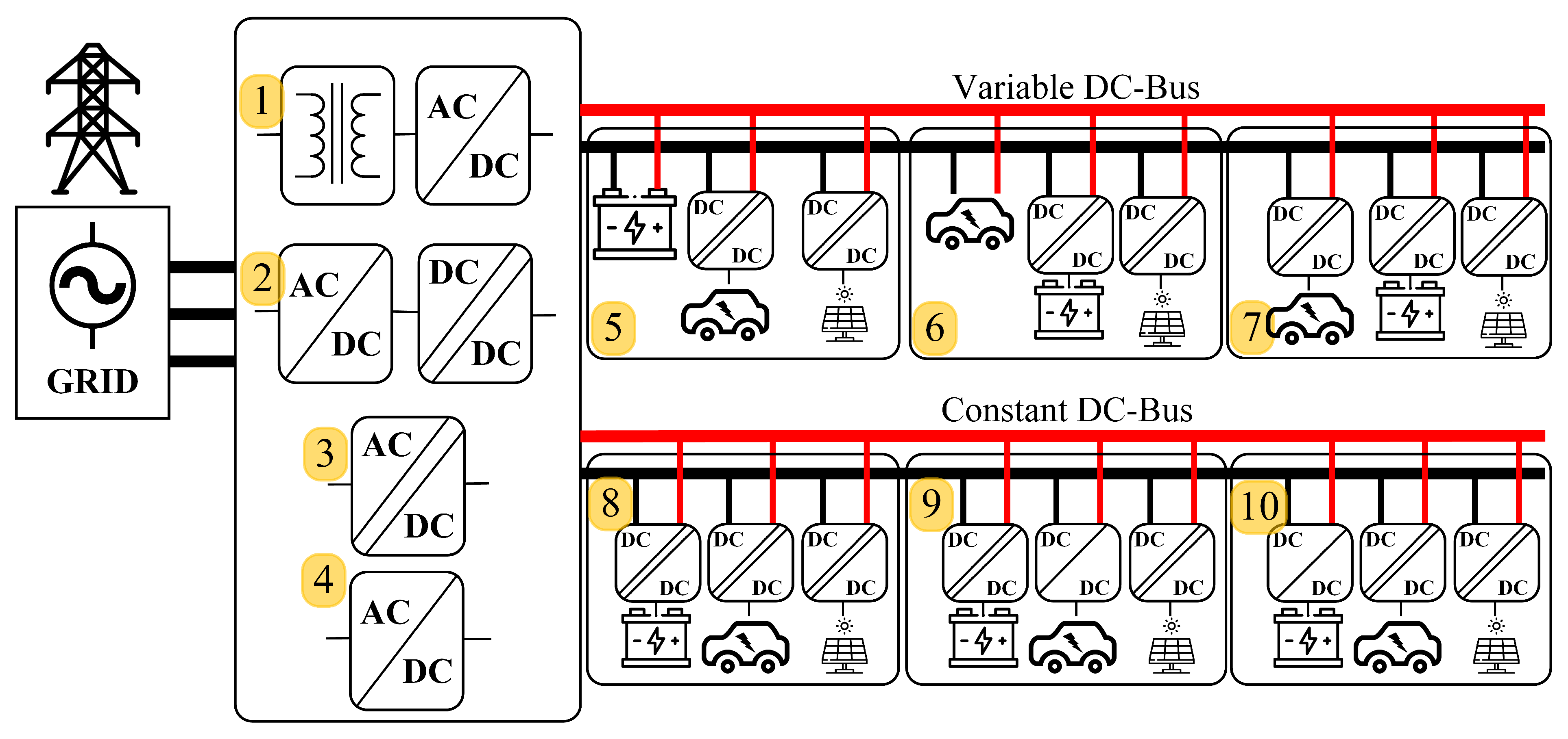
2.1. Variable DC-Bus
2.2. Constant DC-Bus
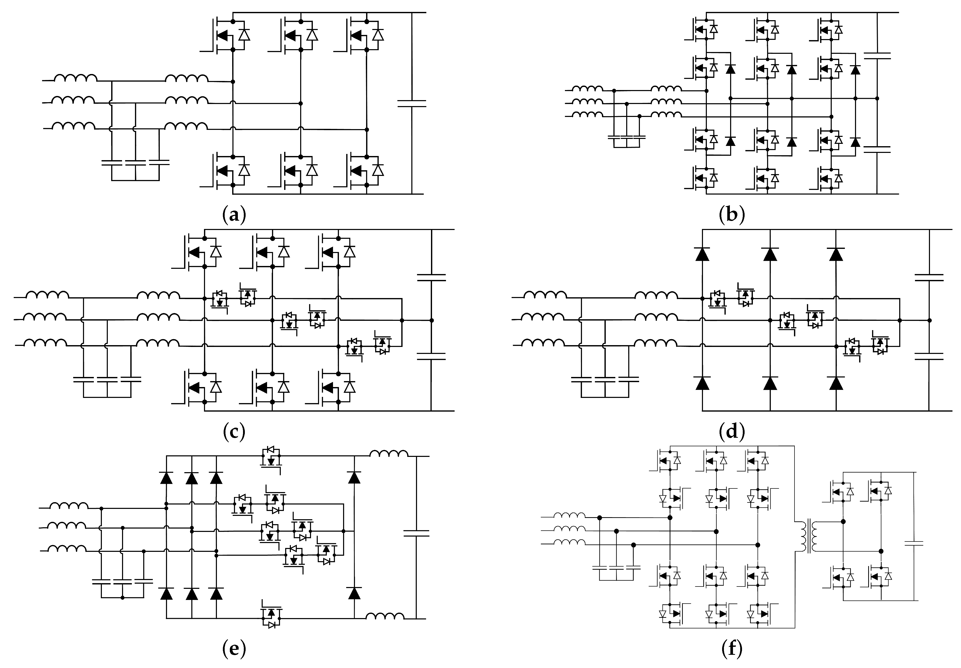
2.3. AC/DC Conversion Stage Topologies
2.4. DC/DC Topologies
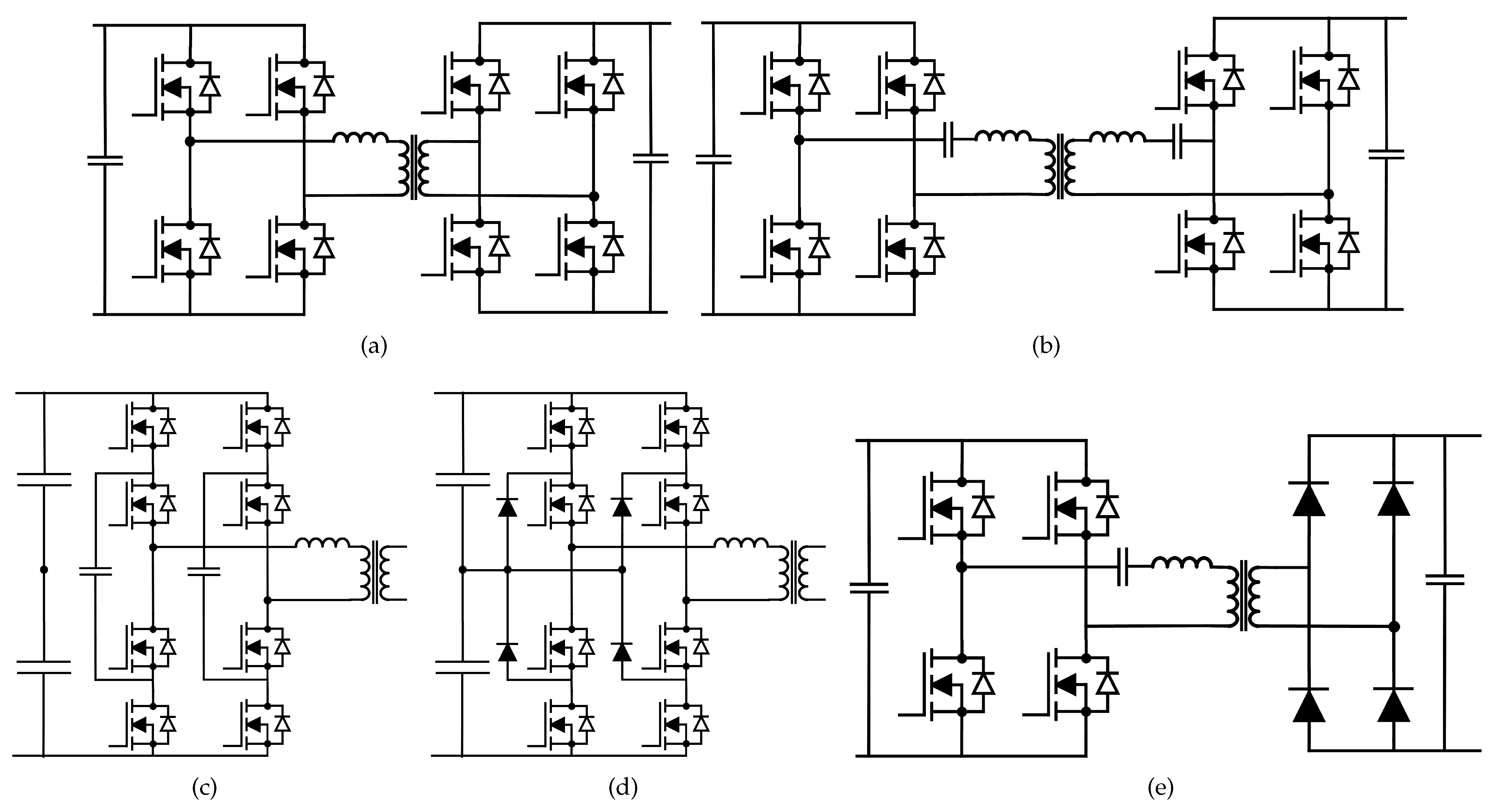
2.4.1. Isolated DC/DC Converters
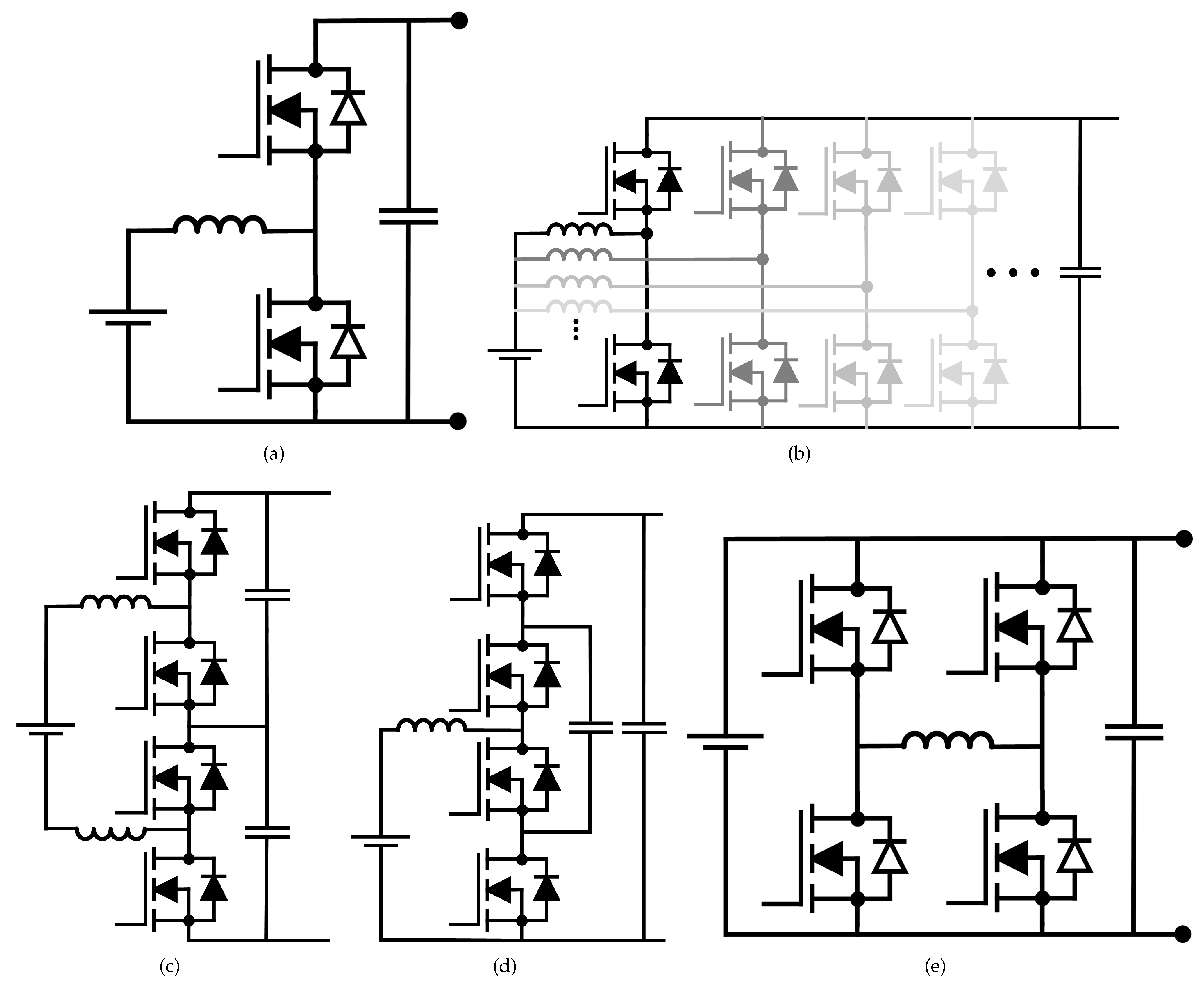
2.4.2. Non-Isolated DC/DC Converters
3. Battery Types
4. Failure Mechanism and Design for Reliability
4.1. Failure Mechanism
4.2. Design for Reliability
4.3. Condition Monitoring and Health Maintenance
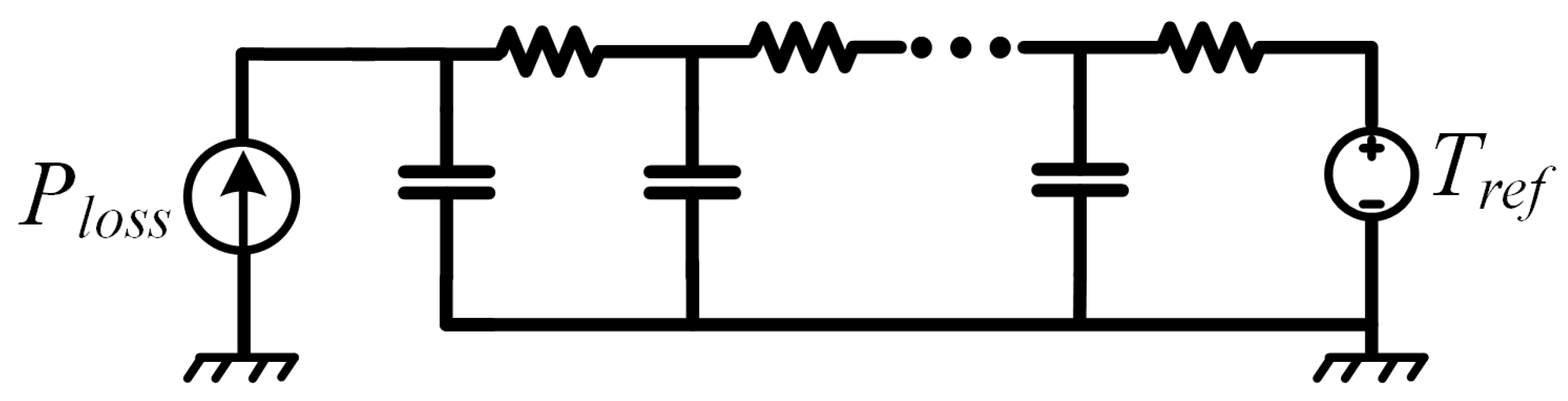
Junction Temperature Estimation Methods
5. Control Methods for DC-Fast Chargers with BESS
5.1. Low-Level Control
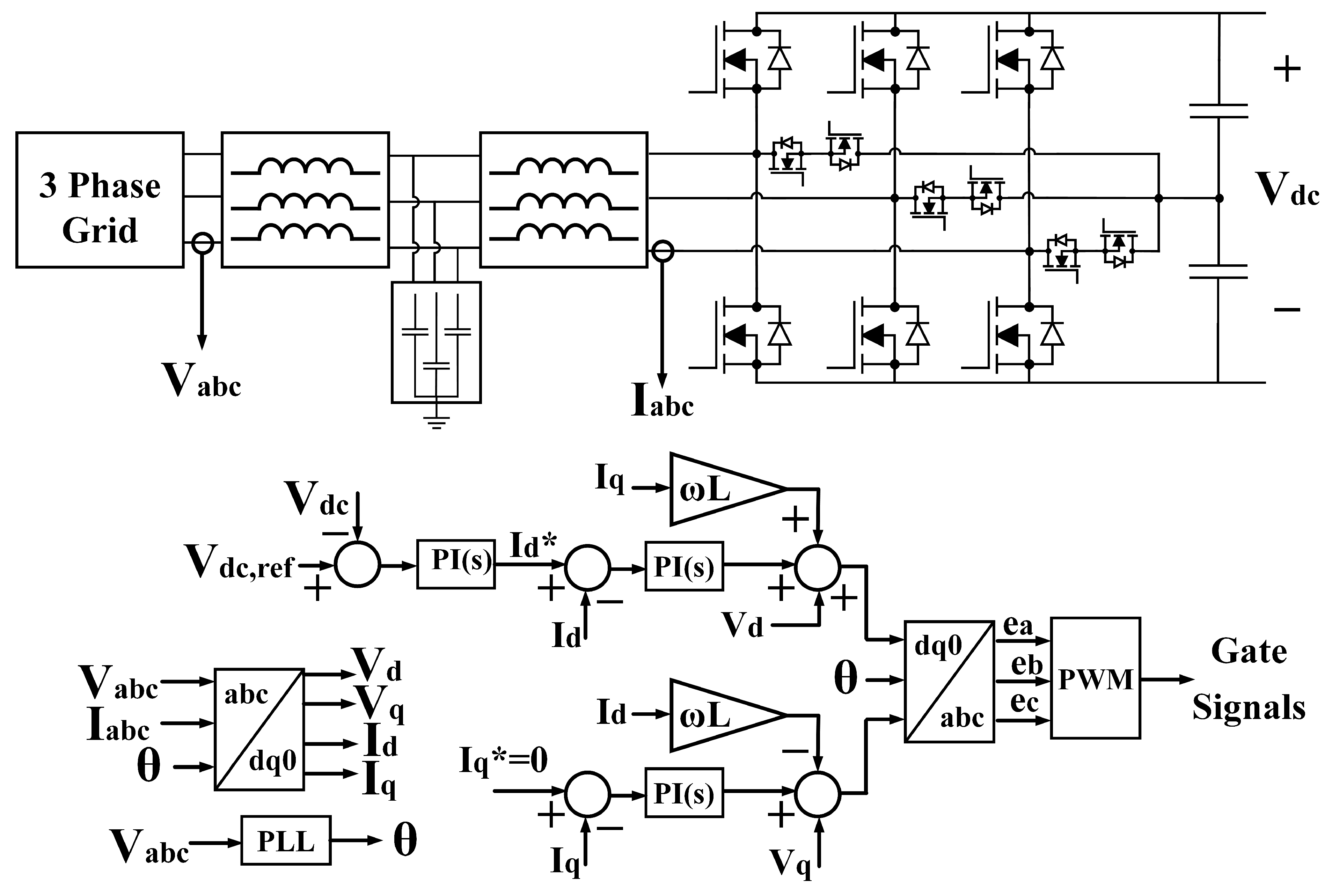
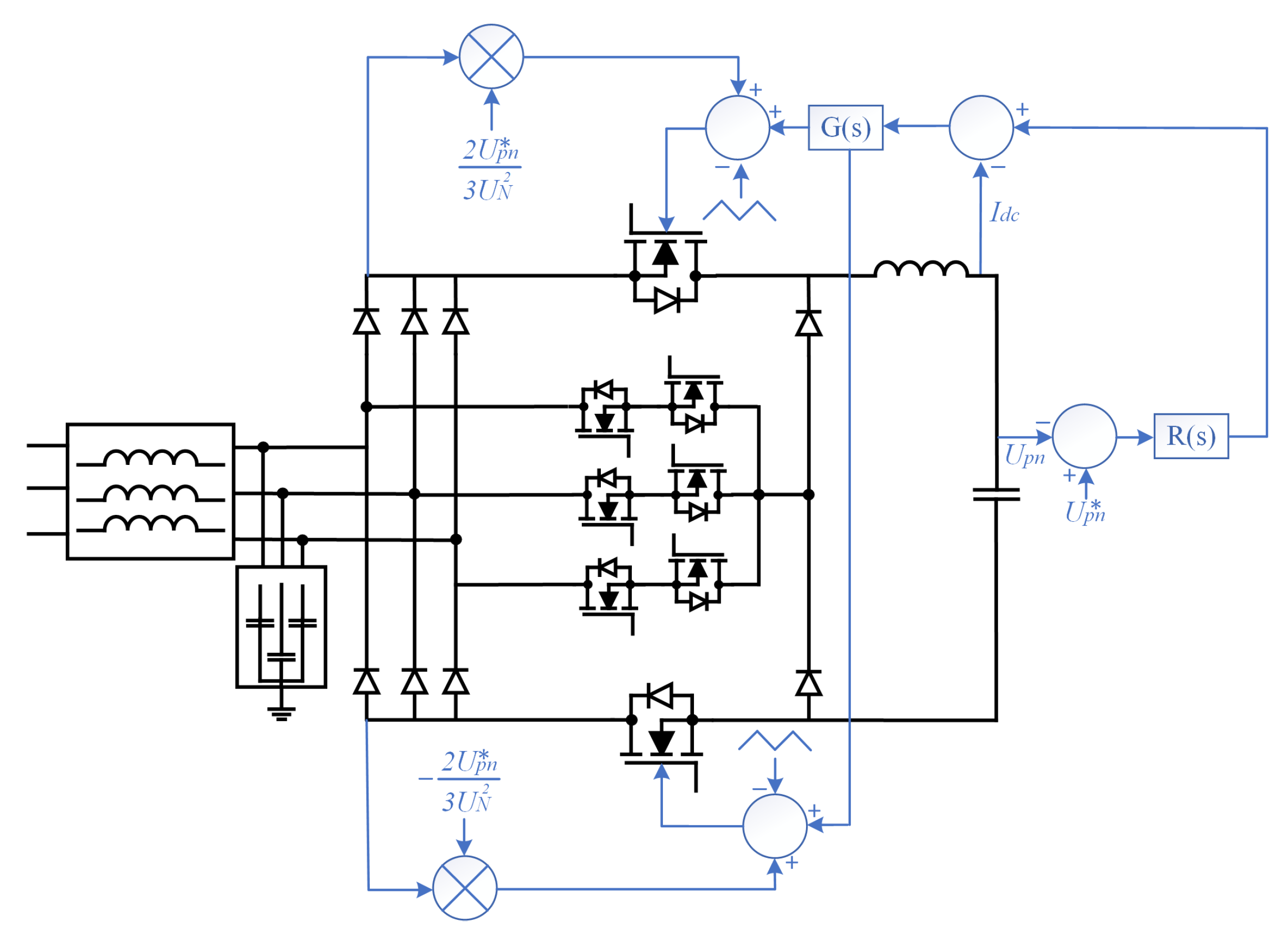
5.1.1. AC/DC Rectifier/Inverter Low-Level Control Methods
5.1.2. DC/DC Converter Low-Level Control Methods
- 1.
- DAB Converter:The DAB converter is an isolated, bidirectional topology with a low number of passive elements. The power flow direction and magnitude are controlled by the phase difference between the primary and secondary side AC voltages with the leakage inductance as the power transfer element. The most common control method is the single phase shift control (SPS) whose power equation is given in Equation (4) where P is the transferred power, are fundamental components of primary and secondary voltages, is the phase difference, is the angular frequency and L is the leakage inductance. An important aspect of Equation (4) is that if is negative, the power flow can be achieved in the opposite direction.In SPS control, the primary side legs are always inversely operated and theoretically, the power flow can be achieved between and zero. Moreover, the DAB converter can achieve soft switching on both sides during its operation which significantly increases the efficiency and reduces EMI and converter size. However, soft switching is only achieved for certain power levels and voltage transfer ratios. A way to increase the range of soft switching is to increase the leakage inductance but it also increases the current stress on the switches due to higher circulating current. In order to increase the light-load efficiency for a wider voltage transfer ratio, other phase shift methods such as double phase shift (DPS) or triple phase shift (TPS) are presented. By optimizing both the internal phase shifts and the voltage phase shifts, it is possible to improve efficiency, improve voltage gain, and lower transformer loss. In [155], the asymmetric phase shift (APS) method is presented and the light load efficiency is improved significantly. In [156], the double band peak current control method is used to improve the light-load efficiency by extending the ZVS range. This method limits the switching current by indirectly changing the switching frequency. In [32], modulation schemes were investigated for a 5-level DAB converter for Ultra-Wide input voltage range applications.
- 2.
- CLLC Converter:Compared to the DAB converter, CLLC converters have a wide output voltage range with an improved light load efficiency due to ZVS operation. In [53], dead-band control with soft-starting capability is presented. In [157], a sliding mode control method is proposed and it is said that the settling time is 0.9 ms shorter than conventional PI control strategies where the SMC settles in 1 ms. In [158], extended phase shift control (EPS) is presented and said to be superior to the pulse frequency modulation method in light loading conditions. In [159], a synchronous rectification (SR) scheme is presented resulting in a reduction in conduction losses by using a MOSFET channel instead of lossy body diodes. It is said that SR is especially critical for SiC applications since the body-diode of SiC MOSFET has a significant voltage drop across its junction.
- 3.
- LLC Converter:Similar to CLLC converters, LLC converters are often controlled by changing the frequency or changing the phase shift or using a combination of both methods [160]. By changing the frequency the reflected impedance is controlled [161] and by changing the phase-shift the power flow is controlled and governed by the same equation presented in Equation (4). However, a downside of the LLC converter is the light load efficiency due to increased switching frequency. To solve the issue magnetic control methods are presented in [162]. The main idea in all magnetic control methods is to intentionally saturate the external leakage inductance to achieve higher light-load efficiencies [163]. This method is similar to phase shift control since instead of changing the phase difference the inductance is changed in Equation (4). In [164], a secondary side phase-shift method is presented, and compared to frequency control, the nominal efficiency is increased and the circulating current is decreased. In [165], an asymmetric duty cycle control is proposed and it is said to decrease the resonant current and the conduction losses of the semiconductors compared to frequency control. In [166], a hybrid PWM and pulse frequency modulation (PFM) is given. Compared to the conventional PFM method, it decreased the current spikes and enhanced output voltage regulation.
5.1.3. Low-Level Reliability Oriented Control Methods
- 1.
- Output Power ControlIn this approach, in case of any increment in junction temperature and its fluctuation, the PEC starts decreasing processing power. However, in the normal case, PEC can deliver rated power while ATC does not have any impact on normal operation [167,168]. Moreover, in PV application, by manipulating the MPPT procedure, the junction temperature of the semiconductors can be controlled [169].
- 2.
- Cooling SystemIn this method, by manipulating cooling effort (i.e., cooling liquid flow rate, fan speed), the junction temperature is controlled [170,171,172]. In [170,171], both feed-forward and closed-loop controllers are used to increase the dynamic response of the system and minimize the temperature variation. Moreover, the ambient temperature in addition to power losses is considered for controlling the cooling system. In [172], by producing a thermal model and tuning the control system around it, junction temperature can be adjusted.
- 3.
- Switching Frequency ControlIn this approach for reducing junction temperature swings and also controlling its mean and maximum value, the switching frequency of PECs is manipulated. Basically, switching frequency changes are associated with switching loss change. To smooth temperature swings, switching frequency should be increased resulting in decreasing efficiency [123,167,173,174,175,176]. However, by using the new generation of power semiconductors such as WBG, efficiency reduction will be less in comparison with normal Si-based semiconductors [177]. Moreover, for controlling mean and maximum value, switching frequency should be decreased [167,178,179,180,181] to reduce losses in the semiconductors. However, due to the dependency of passive components on switching frequency which results in overdesign issues, this approach might not be practical.
- 4.
- Modulation StrategyIn [182], by utilizing reactive power circulation between paralleled PECs, temperature fluctuation can be smoothed. In [183], using the condition monitoring program and estimating the remaining useful lifetime of the semiconductors, to increase the lifetime, other paralleled PECs will be requested to process more power. Authors in [184,185,186], implemented new space vector modulation strategies in 3-level neutral clamped PECs to change thermal distribution among power modules and thus manipulate thermal loading. In [187], via applying carrier-based modulation and redundant switching states, thermal stress can be reduced while healthy semiconductors will not experience more stress and pressure. In [188,189], by utilizing discontinuous modulation (DPWM), switching losses are decreased, and thus, thermal stress can be controlled. In [190], by switching between space vector pulse width modulation (SVPWM) and DPWM strategies in addition to manipulating switching frequency, power dissipation and consequently thermal stress are reduced.
- 5.
- Active Gate Drive ControlControlling gate-drive circuits is one of the hopeful methods for implementing active thermal control. The goal of this method is modifying conduction and switching power losses through controlling the turn ON and turn OFF transition and also the ON-state voltage of MOSFET/ IGBT [191]. In [192], multi-level gate-drive can smooth junction temperature fluctuation by forcing power semiconductors to work in the saturation region. In [177], a two-step gate-driver was proposed which can control rise/fall time during switching instants in GaN HEMTs. Moreover, it was shown that the proposed approach has impacts on conduction losses in case the switching transition exceeds a certain duration. In [193,194,195,196], Wang et al. proposed an ATC method that can impact conduction losses by manipulating gate voltage and consequently drain-source resistance. However, in low gate voltage, the switch might get damaged because of a thermal runaway that can limit its applicability in a vast range of gate voltage. Moreover, in [197], a variable gate voltage methodology was employed to impact switching losses and smooth junction temperature fluctuations. In [198], by using a resistor network and switching between them, the ON/OFF switching transition can be modified according to the output load. In [199], authors could modulate switching losses via employing adaptive gate-drive in addition to controlling switching frequency. Adaptive gate drive can be implemented by changing effective gate resistance. The authors in [200], by using the gate voltage variation method and gate resistance manipulation instantaneously and also measuring junction temperature and making a comparison with the reference value, could modify switching losses and thus control junction temperature variations.
5.2. System-Level Reliability Oriented Control
6. Power Electronics and Battery Cooling Methods
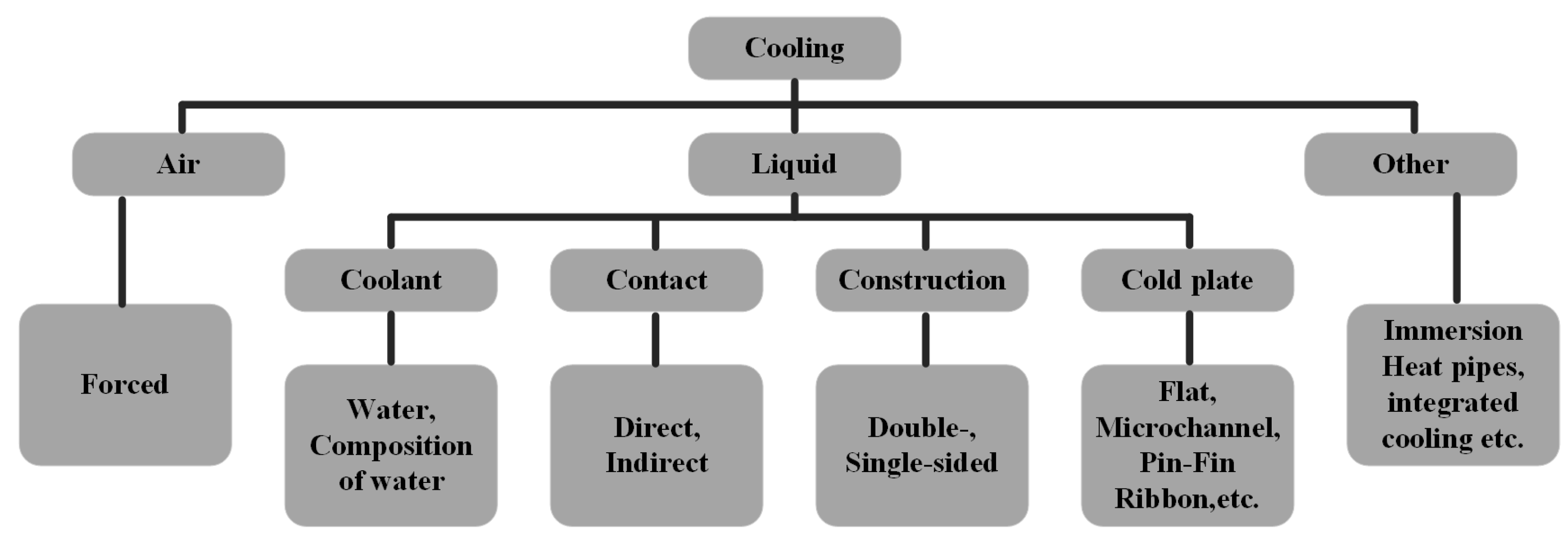
6.1. Power Electronics Cooling Methods
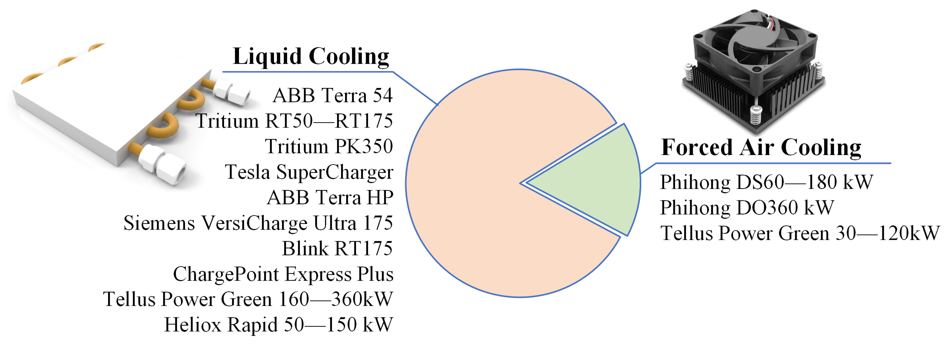
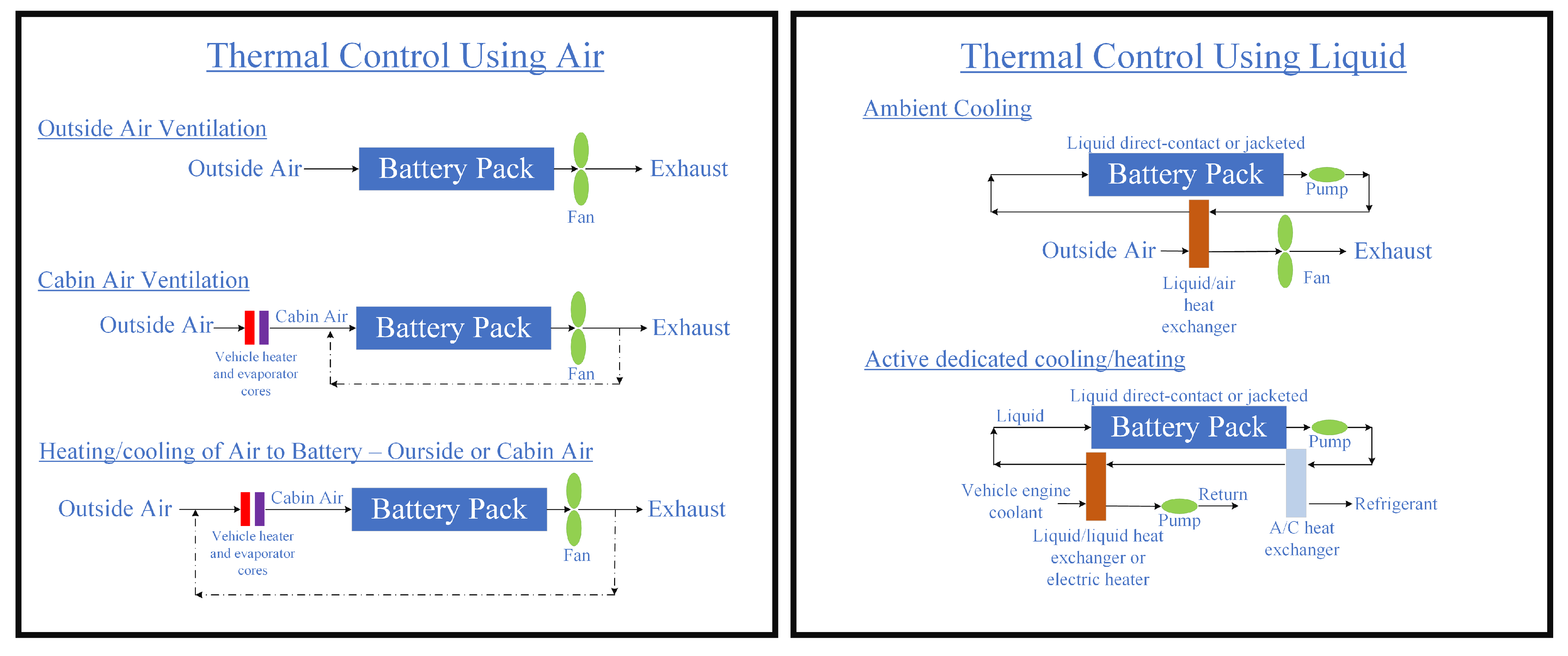
6.2. Stationary and EV Battery Cooling Methods
6.2.1. State-of-the-Art Cooling Methods for Local BESS and EV Batteries
6.2.2. Smart Pre-Conditioning Methods for Battery Charging for Improved Lifetime
- The development of advanced algorithms and machine learning techniques for predicting and optimizing the charging process, in order to minimize stress on the battery and maximize its capacity and longevity [244].
- The development of improved understanding of the effects of different charging protocols, such as the constant current/constant voltage (CC/CV) charging, pulse charging, and others, on the performance and lifetime of the battery [245].
- Studying the interactions between different factors that affect battery charging, such as temperature, state of charge, and charging rate, in order to develop more sophisticated models and algorithms for optimizing the charging process [246].
- Testing and evaluating smart pre-conditioning in different battery chemistries and applications, such as lithium-ion batteries for electric vehicles, stationary energy storage systems, and portable electronic devices.
- Integrating smart pre-conditioning into commercial battery charging systems, in order to demonstrate its benefits and potential for real-world applications.
7. Conclusions
Funding

Acknowledgments
Conflicts of Interest
Abbreviations
| AFE | Active Front End |
| APS | Asymmetric Phase Shift |
| ATC | Active Thermal Control |
| BESS | Battery Energy Storage System |
| CAPEX | Capital Expenditure |
| CPC | Compensated Proportional Controller |
| CTE | Coefficient of Thermal Expansion |
| DAB | Dual Active Bridge |
| DBC | Direct Bonded Copper |
| DfR | Design for Reliability |
| DoD | Depth of Discharge |
| DPS | Double Phase Shift |
| DPWM | Discontinuous PWM |
| EMI | Electro-Magnetic Interference |
| EoL | End of Life |
| EPS | Extended Phase Shift |
| ESS | Energy Storage System |
| EV | Electric Vehicle |
| FC | Flying Capacitor |
| G2V | Grid to Vehicle |
| GaN | Gallium Nitrate |
| HEMT | High Electron Mobility Transistor |
| ICEV | Internal Combustion Engine Vehicle |
| LiB | Lithium-ion Battery |
| MPPT | Maximum Power Point Tracker |
| MTBF | Mean Time between Failure |
| MTTF | Mean Time to Failure |
| NPC | Neutral Point Clamped |
| NTC | Negative Temperature Coefficient |
| OEM | Original Equipment Manufacturer |
| OPEX | Operational Expenditure |
| PCM | Phase Change Material |
| PCS | Phase Change Slurry |
| PEC | Power Electronics Converter |
| PFC | Power Factor Corrector |
| PFM | Pulse Frequency Modulation |
| PHM | Prognostics and Health Management |
| PI | Proportional Integral |
| PLL | Phase Locked Loop |
| RMS | Root Mean Square |
| RUL | Remaining Useful Life |
| SiC | Silicon Carbide |
| SLB | Second Life Battery |
| SMC | Sliding Mode Controller |
| SoC | State of Charge |
| SoH | State of Health |
| SPS | Single Phase Shift |
| SR | Synchronous Rectification |
| SVPWM | Space Vector PWM |
| TDDB | Time Dependent Dielectric Breakdown |
| THD | Total Harmonic Distortion |
| TPS | Triple Phase Shift |
| TSEP | Temperature Sensitive Electrical Parameter |
| V2G | Vehicle to Grid |
| WBG | Wide Band Gap |
| ZCS | Zero Current Switching |
| ZVS | Zero Voltage Switching |
References
- EV Charging Infrastructure Incentives in Europe 2022. Available online: https://blog.evbox.com/ev-charging-infrastructure-incentives-eu (accessed on 17 November 2022).
- When Fossil Fuels Run Out, What Then? Available online: https://mahb.stanford.edu/library-item/fossil-fuels-run/ (accessed on 17 November 2022).
- Emissions by Sector. Available online: https://ourworldindata.org/emissions-by-sector (accessed on 17 November 2022).
- Pevec, D.; Babic, J.; Carvalho, A.; Ghiassi-Farrokhfal, Y.; Ketter, W.; Podobnik, V. Electric Vehicle Range Anxiety: An Obstacle for the Personal Transportation (R)evolution? In Proceedings of the 2019 4th International Conference on Smart and Sustainable Technologies (SpliTech), Split, Croatia, 18–21 June 2019. [Google Scholar]
- Electric Car Range and Affordability: Is There a Magic Combo? Available online: https://insideevs.com/news/380555/ev-range-ev-market-evolution-exposed/ (accessed on 17 November 2022).
- Yilmaz, M.; Krein, P.T. Review of battery charger topologies, charging power levels, and infrastructure for plug-in electric and hybrid vehicles. IEEE Trans. Power Electron. 2013, 28, 2151–2169. [Google Scholar] [CrossRef]
- Johnson, S.C.; Papageorgiou, D.J.; Mallapragada, D.S.; Deetjen, T.A.; Rhodes, J.D.; Webber, M.E. Evaluating rotational inertia as a component of grid reliability with high penetrations of variable renewable energy. Energy 2019, 180, 258–271. [Google Scholar] [CrossRef]
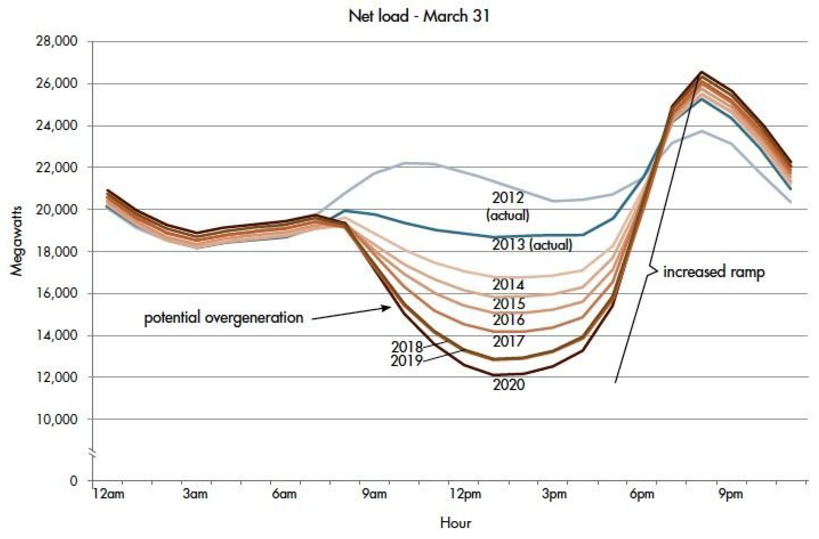
- The Duck Curve on California’s Grid Will Encourage Innovation and Creative Thinking. Available online: https://www.greentechmedia.com/articles/read/californias-duck-curve-will-encourage-innovation (accessed on 17 November 2022).
- Khalid, M.R.; Khan, I.A.; Hameed, S.; Asghar, M.S.J.; Ro, J.S. A Comprehensive Review on Structural Topologies, Power Levels, Energy Storage Systems, and Standards for Electric Vehicle Charging Stations and Their Impacts on Grid. IEEE Access 2021, 9, 128069–128094. [Google Scholar] [CrossRef]
- Kriukov, A.; Gavrilas, M.; Ivanov, O.; Grigoras, G.; Neagu, B.C.; Scarlatache, F. Novel Decentralized Voltage-Centered EV Charging Control Algorithm Using DSRC System in Low Voltage Distribution Networks. IEEE Access 2021, 9, 164779–164800. [Google Scholar] [CrossRef]
- Hua, L.; Wang, J.; Zhou, C. Adaptive electric vehicle charging coordination on distribution network. IEEE Trans. Smart Grid 2014, 5, 2666–2675. [Google Scholar] [CrossRef]
- Bai, S.; Du, Y.; Lukic, S. Optimum design of an EV/PHEV charging station with DC bus and storage system. In Proceedings of the 2010 IEEE Energy Conversion Congress and Exposition, Atlanta, GA, USA, 12–16 September 2010; pp. 1178–1184. [Google Scholar] [CrossRef]
- Rafi, M.A.H.; Bauman, J. A Comprehensive Review of DC Fast-Charging Stations with Energy Storage: Architectures, Power Converters, and Analysis. IEEE Trans. Transp. Electrif. 2021, 7, 345–368. [Google Scholar] [CrossRef]
- Utility-Scale Battery Storage. Available online: https://atb.nrel.gov/electricity/2021/utility-scale_battery_storage (accessed on 17 November 2022).
- Hasan, M.M.; Berseneff, B.; Meulenbroeks, T.; Cantero, I.; Chakraborty, S.; Geury, T.; Hegazy, O. A Multi-Objective Co-Design Optimization Framework for Grid-Connected Hybrid Battery Energy Storage Systems: Optimal Sizing and Selection of Technology. Energies 2022, 15, 5355. [Google Scholar] [CrossRef]
- Laurin, A.; Heiries, V.; Montaru, M. State-of-Charge and State-of-Health online estimation of Li-ion battery for the More Electrical Aircraft based on semi-empirical ageing model and Sigma-Point Kalman Filtering. In Proceedings of the 2021 Smart Systems Integration (SSI), Grenoble, France, 27–29 April 2021; pp. 20–23. [Google Scholar] [CrossRef]
- Hasan, M.M.; Hasan, M.; Chakraborty, S.; Baghdadi, M.E.; Razzak, A. Evaluation of Failure Trends on a PID-Controlled Synchronous Buck Converter based Battery Charging Controller. In Proceedings of the 2020 IEEE International Conference on Power Electronics, Smart Grid and Renewable Energy (PESGRE2020), Cochin, India, 2–4 January 2020; pp. 1–6. [Google Scholar]
- Gonzalez-Hernando, F.; San-Sebastian, J.; Arias, M.; Rujas, A.; Iannuzzo, F. Discontinuous PWM for Online Condition Monitoring of SiC Power Modules. IEEE J. Emerg. Sel. Top. Power Electron. 2020, 8, 323–330. [Google Scholar] [CrossRef]
- Safayatullah, M.; Elrais, M.T.; Ghosh, S.; Rezaii, R.; Batarseh, I. A Comprehensive Review of Power Converter Topologies and Control Methods for Electric Vehicle Fast Charging Applications. IEEE Access 2022, 10, 40753–40793. [Google Scholar] [CrossRef]
- Tu, H.; Feng, H.; Srdic, S.; Lukic, S. Extreme Fast Charging of Electric Vehicles: A Technology Overview. IEEE Trans. Transp. Electrif. 2019, 5, 861–878. [Google Scholar] [CrossRef]
- How Long Does it Take to Charge an Electric Vehicle? Available online: https://carge.co/blog/charging/ev-battery-charging-time (accessed on 17 November 2022).
- Most of The EV Industry to Shift to 800 Volts by 2025, Report Says. Available online: https://insideevs.com/news/580829/ev-industry-shifting-to-800-volt-2025/ (accessed on 17 November 2022).
- Menon, U.; Panda, D. Design and Evaluation of Electric Bus Systems for Metropolitan Cities. Int. J. Mech. Eng. 2020, 7, 16–23. [Google Scholar] [CrossRef]
- Terra HP Charger-Up to 350, kW. Available online: https://new.abb.com/ev-charging/high-power-charging (accessed on 17 November 2022).
- Terra 54 CJG. Available online: https://new.abb.com/ev-charging/dc-fast-chargers/terra-54-cjg (accessed on 17 November 2022).
- Ultra 175 DC Charger. Available online: https://assets.new.siemens.com/siemens/assets/api/uuid:1777fe11-fa33-45f6-a339-bd522d5f6059/sidst40085004auslores.pdf (accessed on 17 November 2022).
- EVBox Troniq Modular. Available online: https://evbox.com/en/ev-chargers/troniq-modular (accessed on 17 November 2022).
- Supercharger. Available online: https://www.tesla.com/eneu/supercharger (accessed on 17 November 2022).
- Heliox Rapid 50–300, kW. Available online: https://www.heliox-energy.com/products/rapid-150kw-modular (accessed on 17 November 2022).
- Electric Vehicle Conductive Charging System—Part 23: DC Electric Vehicle Charging Station. Available online: https://www.iecee.org/dyn/www/f?p=106:49:0::::FSP_STD_ID:6032 (accessed on 17 November 2022).
- Safety of Power Converters for Use in Photovoltaic Power Systems—Part 1: General Requirements. Available online: https://webstore.iec.ch/publication/6470 (accessed on 17 November 2022).
- Bezerra, P.A.; Krismer, F.; Burkart, R.M.; Kolar, J.W. Bidirectional Isolated Non-Resonant DAB DC-DC Converter for Ultra-Wide Input Voltage Range Applications. In Proceedings of the 2014 International Power Electronics and Application Conference and Exposition, Shanghai, China, 5–8 November 2014; pp. 1038–1044. [Google Scholar] [CrossRef]
- Design Guide: TIDA-010054 Bidirectional, Dual Active Bridge Reference Design for Level 3 Electric Vehicle Charging Stations. 2022. Available online: https://www.ti.com/tool/TIDA-010054 (accessed on 17 November 2022).
- Kumar, R.; Singh, B. Matrix converter based three phase isolated ev charger with direct power control. In Proceedings of the 2020 IEEE International Conference on Power Electronics, Drives and Energy Systems (PEDES), Jaipur, India, 16–19 December 2020. [Google Scholar] [CrossRef]
- Jahnes, M.; Zhou, L.; Eull, M.; Wang, W.; Preindl, M. Design of a 22kW Transformerless EV Charger With V2G Capabilities and Peak 99.5% Efficiency. IEEE Trans. Ind. Electron. 2022, 70, e3192697. [Google Scholar] [CrossRef]
- Rasool, H.; Verbrugge, B.; Zhaksylyk, A.; Tran, T.M.; Baghdadi, M.E.; Geury, T.; Hegazy, O. Design Optimization and Electro-Thermal Modeling of an Off-Board Charging System for Electric Bus Applications. IEEE Access 2021, 9, 84501–84519. [Google Scholar] [CrossRef]
- Mortezaei, A.; Abdul-Hak, M.; Simoes, M.G. A Bidirectional NPC-based Level 3 EV Charging System with Added Active Filter Functionality in Smart Grid Applications. In Proceedings of the 2018 IEEE Transportation Electrification Conference and Expo (ITEC), Long Beach, CA, USA, 13–15 June 2018; pp. 1065–1070. [Google Scholar] [CrossRef]
- Schweizer, M.; Kolar, J.W. Design and implementation of a highly efficient three-level T-type converter for low-voltage applications. IEEE Trans. Power Electron. 2013, 28, 899–907. [Google Scholar] [CrossRef]
- Bolsi, P.C.; Prado, E.O.; Sartori, H.C.; Lenz, J.M.; Pinheiro, J.R. LCL Filter Parameter and Hardware Design Methodology for Minimum Volume Considering Capacitor Lifetimes. Energies 2022, 15, 4420. [Google Scholar] [CrossRef]
- Liu, Q.; Peng, L.; Kang, Y.; Tang, S.; Wu, D.; Qi, Y. A novel design and optimization method of an LCL filter for a shunt active power filter. IEEE Trans. Ind. Electron. 2014, 61, 4000–4010. [Google Scholar] [CrossRef]
- Yu, L.; Peng, X.; Gao, S. Voltage-balancing strategy for three-level neutral point clamped cascade converter under sequence pulse modulation. Energies 2019, 12, 3829. [Google Scholar] [CrossRef]
- Kolar, J.W.; Drofenik, U.; Zach, F.C. VIENNA rectifier II—A novel single-stage high-frequency isolated three-phase PWM rectifier system. IEEE Trans. Ind. Electron. 1999, 46, 674–691. [Google Scholar] [CrossRef]
- Soeiro, T.B.; Friedli, T.; Kolar, J.W. Swiss rectifier—A novel three-phase buck-type PFC topology for Electric Vehicle battery charging. In Proceedings of the 2012 Twenty-Seventh Annual IEEE Applied Power Electronics Conference and Exposition (APEC), Orlando, FL, USA, 5–9 February 2012; pp. 2617–2624. [Google Scholar] [CrossRef]
- Schrittwieser, L.; Leibl, M.; Haider, M.; Thony, F.; Kolar, J.W.; Soeiro, T.B. 99.3% Efficient three-phase buck-type all-SiC SWISS Rectifier for DC distribution systems. IEEE Trans. Power Electron. 2017, 34, 2173–2178. [Google Scholar] [CrossRef]
- Monteiro, V.; Pinto, J.G.; Afonso, J.L. Operation Modes for the Electric Vehicle in Smart Grids and Smart Homes: Present and Proposed Modes. IEEE Trans. Veh. Technol. 2016, 65, 1007–1020. [Google Scholar] [CrossRef]
- Naghibi, B.; Masoum, M.A.S.; Deilami, S. Effects of V2H Integration on Optimal Sizing of Renewable Resources in Smart Home Based on Monte Carlo Simulations. IEEE Power Energy Technol. Syst. J. 2018, 5, 73–84. [Google Scholar] [CrossRef]
- Grid-Connected Electric Buses Could Displace Diesels Electric Bus Batteries Could Earn Payments with Local Grid Operator While Providing Health Benefits to Children. Available online: https://spectrum.ieee.org/gridconnected-electric-buses-could-displace-diesels (accessed on 17 November 2022).
- Schrittwieser, L.; Leibl, M.; Kolar, J.W. 99% Efficient isolated three-phase matrix-type DAB buck-boost PFC rectifier. IEEE Trans. Power Electron. 2020, 35, 138–157. [Google Scholar] [CrossRef]
- Zhang, L.; Zheng, Z.; Lou, X. A review of WBG and Si devices hybrid applications. Chin. J. Electr. Eng. 2021, 7, 1–20. [Google Scholar] [CrossRef]
- Hoek, H.V.; Neubert, M.; Doncker, R.W.D. Enhanced modulation strategy for a three-phase dual active bridge—Boosting efficiency of an electric vehicle converter. IEEE Trans. Power Electron. 2013, 28, 5499–5507. [Google Scholar] [CrossRef]
- Hou, N.; Li, Y.W. Overview and Comparison of Modulation and Control Strategies for a Nonresonant Single-Phase Dual-Active-Bridge DC-DC Converter. IEEE Trans. Power Electron. 2020, 35, 3148–3172. [Google Scholar] [CrossRef]
- Chen, W.; Rong, P.; Lu, Z. Snubberless bidirectional DC-DC converter with new CLLC resonant tank featuring minimized switching loss. IEEE Trans. Ind. Electron. 2010, 57, 3075–3086. [Google Scholar] [CrossRef]
- Jung, J.H.; Kim, H.S.; Ryu, M.H.; Baek, J.W. Design methodology of bidirectional CLLC resonant converter for high-frequency isolation of DC distribution systems. IEEE Trans. Power Electron. 2013, 28, 1741–1755. [Google Scholar] [CrossRef]
- Liu, Y.; Du, G.; Wang, X.; Lei, Y. Analysis and design of high-efficiency bidirectional GaN-based CLLC resonant converter. Energies 2019, 12, 3859. [Google Scholar] [CrossRef]
- Bidirectional CLLLC Resonant Dual Active Bridge (DAB) Reference Design for HEV/EV Onboard Charger. Available online: https://www.ti.com/lit/ug/tidueg2c/tidueg2c.pdf?ts=1669172223698 (accessed on 17 November 2022).
- Chakraborty, S.; Hasan, M.M.; Tran, D.D.; Jaman, S.; Bossche, P.V.D.; Baghdadi, M.E.; Hegazy, O. Reliability Assessment of a WBG-based Interleaved Bidirectional HV DC/DC Converter for Electric Vehicle Drivetrains. In Proceedings of the 2020 15th International Conference on Ecological Vehicles and Renewable Energies (EVER), Monte-Carlo, Monaco, 10–12 September 2020. [Google Scholar] [CrossRef]
- Higa, H.; Itoh, J.I. Derivation of operation mode for flying capacitor topology applied to three-level DAB converter. In Proceedings of the 2015 IEEE 2nd International Future Energy Electronics Conference (IFEEC), Taipei, Taiwan, 1–4 November 2015. [Google Scholar] [CrossRef]
- Feng, H.; Teng, F.; Montes, O.A.; Awal, M.A.; Bipu, M.R.H.; Husain, I.; Lukic, S. Passive Capacitor Voltage Balancing of SiC-Based Three-Level Dual-Active-Bridge Converter Using Hybrid NPC-Flying Capacitor Structure. IEEE Trans. Power Electron. 2022, 37, 4183–4194. [Google Scholar] [CrossRef]
- Awal, M.A.; Bipu, M.R.H.; Montes, O.A.; Feng, H.; Husain, I.; Yu, W.; Lukic, S. Capacitor Voltage Balancing for Neutral Point Clamped Dual Active Bridge Converters. IEEE Trans. Power Electron. 2020, 35, 11267–11276. [Google Scholar] [CrossRef]
- Designing an LLC Resonant Half-Bridge Power Converter. Available online: https://www.ti.com/seclit/ml/slup263/slup263.pdf (accessed on 17 November 2022).
- Resonant LLC Converter: Operation and Design. Available online: https://www.infineon.com/dgdl/Application_Note_Resonant+LLC+Converter+Operation+and+Design_Infineon.pdf?fileId=db3a30433a047ba0013a4a60e3be64a1 (accessed on 17 November 2022).
- Huber, J.E.; Minibock, J.; Kolar, J.W. Generic Derivation of Dynamic Model for Half-Cycle DCM Series Resonant Converters. IEEE Trans. Power Electron. 2018, 33, 4–7. [Google Scholar] [CrossRef]
- Alharbi, M.A.; Alcaide, A.M.; Dahidah, M.; Montero-Robina, P.; Ethni, S.; Pickert, V.; Leon, J.I. Rotating Phase-Shedding for Interleaved DC-DC Converter-Based EVs Fast DC Chargers. IEEE Trans. Power Electron. 2022, 38, 1901–1909. [Google Scholar] [CrossRef]
- Carstensen, C.; Biela, J. A Three-Level Buck Converter with a Wide Voltage Operation Range for Hardware-in-the-Loop Test Systems. IEEE Trans. Power Electron. 2016, 31, 6176–6191. [Google Scholar] [CrossRef]
- Song, L.; Duan, S.; Wang, T.; Liu, X. A Simplified Flying Capacitor Voltage Control Strategy for Hybrid Clamped Three-Level Boost Converter in Photovoltaic System. IEEE Trans. Ind. Electron. 2022, 69, 8004–8014. [Google Scholar] [CrossRef]
- Qian, W.; Cha, H.; Peng, F.Z.; Tolbert, L.M. 55-kW variable 3X DC-DC converter for plug-in hybrid electric vehicles. IEEE Trans. Power Electron. 2012, 27, 1668–1678. [Google Scholar] [CrossRef]
- Keyhani, H.; Toliyat, H.A. Flying-capacitor boost converter. In Proceedings of the 2012 Twenty-Seventh Annual IEEE Applied Power Electronics Conference and Exposition (APEC), Orlando, FL, USA, 5–9 February 2012; pp. 2311–2318. [Google Scholar] [CrossRef]
- Schaltz, E.; Rasmussen, P.O.; Khaligh, A. Non-Inverting Buck-Boost Converter for Fuel Cell Applications. In Proceedings of the 2008 34th Annual Conference of IEEE Industrial Electronics, Orlando, FL, USA, 10–13 November 2008. [Google Scholar] [CrossRef]
- Rao, A.V.; Guruswamy, K.P. Analysis, Design and Simulation of Non-Inverting Buck-Boost DC-DC Converter for Battery Charging. In Proceedings of the 2021 International Conference on Disruptive Technologies for Multi-Disciplinary Research and Applications (CENTCON), Bengaluru, India, 19–21 November 2021; pp. 79–84. [Google Scholar] [CrossRef]
- Ayuso, P.; Beltran, H.; Segarra-Tamarit, J.; Pérez, E. Optimized profitability of LFP and NMC Li-ion batteries in residential PV applications. Math. Comput. Simul. 2021, 183, 97–115. [Google Scholar] [CrossRef]
- Tran, M.K.; Dacosta, A.; Mevawalla, A.; Panchal, S.; Fowler, M. Comparative study of equivalent circuit models performance in four common lithium-ion batteries: LFP, NMC, LMO, NCA. Batteries 2021, 7, 51. [Google Scholar] [CrossRef]
- Murdock, B.E.; Toghill, K.E.; Tapia-Ruiz, N. A Perspective on the Sustainability of Cathode Materials used in Lithium-Ion Batteries. Adv. Energy Mater. 2021, 11, e202102028. [Google Scholar] [CrossRef]
- Baloyi, T.; Chowdhury, S. Sizing and selection of battery energy storage system for time of use arbitrage in a commercial building in South Africa. In Proceedings of the 2021 IEEE PES/IAS PowerAfrica, Nairobi, Kenya, 23–27 August 2021. [Google Scholar] [CrossRef]
- BU-205: Types of Lithium-Ion. Available online: https://batteryuniversity.com/article/bu-205-types-of-lithium-ion (accessed on 17 November 2022).
- Electricity Storage and Renewables: Costs and Markets to 2030. Available online: https://www.irena.org/publications/2017/oct/electricity-storage-and-renewables-costs-and-markets (accessed on 17 November 2022).
- Li-Ion Batteries for Mobility and Stationary Storage Applications. Available online: https://publications.jrc.ec.europa.eu/repository/handle/JRC113360 (accessed on 17 November 2022).
- Shahjalal, M.; Roy, P.K.; Shams, T.; Fly, A.; Chowdhury, J.I.; Ahmed, M.R.; Liu, K. A review on second-life of Li-ion batteries: Prospects, challenges, and issues. Energy 2022, 241, 122881. [Google Scholar] [CrossRef]
- Rybarik, M.; Bracinik, P.; Kajanova, M. Overview of the Usability of Second-Life Batteries in Smart Distribution Grids. In Proceedings of the 2022 Elektro (Elektro), Krakow, Poland, 23–26 May 2022. [Google Scholar] [CrossRef]
- Second-life EV batteries: The Newest Value Pool in Energy Storage. Available online: https://www.mckinsey.com/industries/automotive-and-assembly/our-insights/second-life-ev-batteries-the-newest-value-pool-in-energy-storage (accessed on 17 November 2022).
- Reinhardt, R.; Christodoulou, I.; Gassó-Domingo, S.; García, B.A. Towards sustainable business models for electric vehicle battery second use: A critical review. J. Environ. Manag. 2019, 245, 432–446. [Google Scholar] [CrossRef]
- Zhu, J.; Mathews, I.; Ren, D.; Li, W.; Cogswell, D.; Xing, B.; Sedlatschek, T.; Kantareddy, S.N.R.; Yi, M.; Gao, T.; et al. End-of-life or second-life options for retired electric vehicle batteries. Cell Rep. Phys. Sci. 2021, 2, e100537. [Google Scholar] [CrossRef]
- Chakraborty, S. Real-Life Mission Profile Oriented Lifetime Estimation of a SiC Interleaved Bidirectional HV DC/DC Converter for Electric Vehicle Drivetrains. IEEE J. Emerg. Sel. Top. Power Electron. 2021, 10, 5142–5167. [Google Scholar] [CrossRef]
- Xiang, D.; Ran, L.; Tavner, P.; Yang, S.; Bryant, A.; Mawby, P. Condition monitoring power module solder fatigue using inverter harmonic identification. IEEE Trans. Power Electron. 2011, 27, 235–247. [Google Scholar] [CrossRef]
- Degrenne, N.; Ewanchuk, J.; David, E.; Boldyrjew, R.; Mollov, S. A review of prognostics and health management for power semiconductor modules. In Proceedings of the Annual Conference of the Prognostics and Health Management Society, PHM, Beijing, China, 21–23 October 2015; pp. 242–252. [Google Scholar]
- Hanif, A.; Yu, Y.; Devoto, D.; Khan, F. A Comprehensive Review Toward the State-of-the-Art in Failure and Lifetime Predictions of Power Electronic Devices. IEEE Trans. Power Electron. 2018, 34, 4729–4746. [Google Scholar] [CrossRef]
- Kovačević, I.; Drofenik, U.; Kolar, J. New physical model for lifetime estimation of power modules. In Proceedings of the International Power Electronics Conference—ECCE Asia, IPEC, Sapporo, Japan, 21–24 June 2010; pp. 2106–2114. [Google Scholar] [CrossRef]
- Halim, M.; Buniyamin, N.; Naoe, N.; Rosman, M. An Overview of Data-Driven and Model-Driven Based Prognostics Techniques for Power Modules. In Proceedings of the 4th International Conference on Electrical, Electronics and System Engineering, ICEESE, Kuala Lumpur, Malaysia, 8–9 November 2018; pp. 34–39. [Google Scholar] [CrossRef]
- Faure, D.; Bru, D.; Ali, C.; Giret, C.; Christensen, K. Gate oxide breakdown characterization on 0.13um CMOS technology. Microelectron. Reliab. 2003, 43, 1519–1523. [Google Scholar] [CrossRef]
- Nasrin, M.; Khan, F.; Alam, M. Quantifying device degradation in live power converters using SSTDR assisted impedance Matrix. IEEE Trans. Power Electron. 2013, 29, 3116–3131. [Google Scholar] [CrossRef]
- Lelis, A.; Green, R.; Habersat, D.; El, M. Basic mechanisms of threshold-voltage instability and implications for reliability testing of SiC MOSFETs. IEEE Trans. Electron. Dev. 2014, 62, 316–323. [Google Scholar] [CrossRef]
- Wu, W. SEM investigation on IGBT latch-up failure. In Proceedings of the 2001 6th International Conference on Solid-State and Integrated Circuit Technology. Proceedings (Cat. No. 01EX443), Shanghai, China, 22–25 October 2001; pp. 1040–1042. [Google Scholar] [CrossRef]
- Singh, P. Power MOSFET failure mechanisms. In Proceedings of the 26th Annual International Telecommunications Energy Conference, Chicago, IL, USA, 19–23 September 2004; pp. 499–502. [Google Scholar] [CrossRef]
- Patil, N.; Celaya, J.; Das, D.; Goebel, K.; Pecht, M. Precursor parameter identification for insulated gate bipolar transistor (IGBT) prognostics. IEEE Trans. Reliab. 2009, 58, 271–276. [Google Scholar] [CrossRef]
- Ma, J. Study of Gate Oxide Breakdown and Hot Electron Effect on Cmos Circuit Performances; University of Central Florida: Orlando, FL, USA, 2009. [Google Scholar]
- Xiong, Y.; Cheng, X.; Shen, Z.; Mi, C.; Wu, H.; Garg, V. Prognostic and warning system for power-electronic modules in electric, hybrid electric, and fuel-cell vehicles. IEEE Trans. Ind. Electron. 2008, 55, 2268–2276. [Google Scholar] [CrossRef]
- Ramminger, S.; Seliger, N.; Wachutka, G. Reliability model for Al wire bonds subjected to heel crack failures. Microelectron. Reliab. 2000, 40, 1521–1525. [Google Scholar] [CrossRef]
- Lutz, J.; Schlangenotto, H.; Scheuermann, U.; Doncker, R.D. Semiconductor Power Devices; Springer: Berlin/Heidelberg, Germany, 2011. [Google Scholar] [CrossRef]
- Testa, A. Stress analysis and lifetime estimation on power MOSFETs for automotive ABS systems. In Proceedings of the 2008 IEEE Power Electronics Specialists Conference, Rhodes, Greece, 15–19 June 2008; pp. 1169–1175. [Google Scholar] [CrossRef]
- Patil, S.; Waghmare, G. Determination of Thermal Induced Stresses in Semiconductor Chip Package by using Finite Element Analysis: A Brief Review. Int. J. Eng. Res. Technol. 2015, V4, 44–47. [Google Scholar] [CrossRef]
- Katsis, D.C.; vanWyk, J. A thermal, mechanical, and electrical study of voiding in the solder die-attach of power MOSFETs. IEEE Trans. Components Packag. Technol. 2005, 29, 127–136. [Google Scholar] [CrossRef]
- Huang, H.; Mawby, P. A lifetime estimation technique for voltage source inverters. IEEE Trans. Power Electron. 2012, 28, 4113–4119. [Google Scholar] [CrossRef]
- Nwanoro, K.; Lu, H.; Yin, C.; Bailey, C. An analysis of the reliability and design optimization of aluminium ribbon bonds in power electronics modules using computer simulation method. Microelectron. Reliab. 2018, 87, 1–14. [Google Scholar] [CrossRef]
- Dusmez, S.; Akin, B. An accelerated thermal aging platform to monitor fault precursor on-state resistance. In Proceedings of the 2015 IEEE International Electric Machines & Drives Conference (IEMDC), Coeur d’Alene, ID, USA, 10–13 May 2015; pp. 1352–1358. [Google Scholar] [CrossRef]
- Ciappa, M.; Fichtner, W. Lifetime prediction of IGBT modules for traction applications. In Proceedings of the 2000 IEEE International Reliability Physics Symposium Proceedings, 38th Annual (Cat. No. 00CH37059), San Jose, CA, USA, 10–13 April 2000; pp. 210–216. [Google Scholar] [CrossRef]
- Ciappa, M. Selected failure mechanisms of modern power modules. Microelectron. Reliab. 2002, 42, 653–667. [Google Scholar] [CrossRef]
- Cui, H. Accelerated temperature cycle test and Coffin-Manson model for electronic packaging. In Proceedings of the Annual Reliability and Maintainability Symposium, Alexandria, VA, USA, 24–27 January 2005; pp. 556–560. [Google Scholar] [CrossRef]
- Bayerer, R.; Herrmann, T.; Licht, T.; Lutz, J.; Feller, M. Model for power cycling lifetime of IGBT modules—Various factors influencing lifetime. In Proceedings of the 5th International Conference on Integrated Power Electronics Systems, Nuremberg, Germany, 11–13 March 2008; pp. 37–42. [Google Scholar]
- Scheuermann, U.; Schmidt, R. A new lifetime model for advanced power modules with sintered chips and optimized Al wire bonds. PCIM Eur. Conf. Proc. 2013, 2013, 810–817. [Google Scholar]
- Wileman, A.; Perinpanayagam, S.; Aslam, S. Physics of failure (PoF) based lifetime prediction of power electronics at the printed circuit board level. Appl. Sci. 2021, 11, 2679. [Google Scholar] [CrossRef]
- Ma, K.; Yang, Y.; Wang, H.; Blaabjerg, F. Design for reliability of power electronics in renewable energy systems. In Use, Operation and Maintenance of Renewable Energy Systems; Green Energy and Technology; Springer: Cham, Switzerland, 2014. [Google Scholar] [CrossRef]
- Wang, H.; Ma, K.; Blaabjerg, F. Design for reliability of power electronic systems. In Proceedings of the IECON 2012—38th Annual Conference on IEEE Industrial Electronics Society, Montreal, QC, Canada, 25–28 October 2012; pp. 33–44. [Google Scholar] [CrossRef]
- Ma, K.; Liserre, M.; Blaabjerg, F.; Kerekes, T. Thermal loading and lifetime estimation for power device considering mission profiles in wind power converter. IEEE Trans. Power Electron. 2014, 30, 590–602. [Google Scholar] [CrossRef]
- Kovaltchouk, T.; Aubry, J.; Multon, B.; Ahmed, H. Influence of IGBT current rating on the thermal cycling lifetime of a power electronic active rectifier in a direct wave energy converter. In Proceedings of the 2013 15th European Conference on Power Electronics and Applications, Lille, France, 2–6 September 2013; pp. 1–10. [Google Scholar] [CrossRef]
- Song, Y.; Wang, B. Evaluation Methodology and Control Strategies for Improving Reliability of HEV Power Electronic System. IEEE Trans. Veh. Technol. 2014, 63, 3661–3676. [Google Scholar] [CrossRef]
- Murken, M.; Gratzfeld, P. Reliability Comparison of Bidirectional Automotive DC/DC Converters. In Proceedings of the 2017 IEEE 86th Vehicular Technology Conference (VTC-Fall), Toronto, ON, Canada, 24–27 September 2017; pp. 1–7. [Google Scholar] [CrossRef]
- Ciappa, M.; Carbognani, F.; Cova, P.; Fichtner, W. A Novel Thermomechanics -Based Lifetime Prediction Model for Cycle Fatigue Failure Mechanisms in Power Semiconductors. Microelectron. Reliab. 2002, 42, 1653–1658. [Google Scholar] [CrossRef]
- Mainka, K.; Thoben, M.; Schilling, O. Lifetime calculation for power modules, application and theory of models and counting methods. In Proceedings of the 2011 14th European Conference on Power Electronics and Applications, Birmingham, UK, 30 August–1 September 2011; pp. 1–8. [Google Scholar]
- Matsuichi, M.; Endo, T. Fatigue of metals subjected to varying stress. Engineering 1968. [Google Scholar]
- Lu, H.; Tilford, T.; Bailey, C.; Newcombe, D. Lifetime prediction for power electronics module substrate mount-down solder interconnect. In Proceedings of the International Symposium on High Density Packaging and Microsystem Integration, Shanghai, China, 26–28 June 2007. [Google Scholar] [CrossRef]
- Miner, M.A. Cumulative Damage in Fatigue. J. Appl. Mech. 2021, 12, A159–A164. [Google Scholar] [CrossRef]
- Schulz, M.; Xin, M. Correlating NTC-reading and chip-Temperature in power electronic modules. In Proceedings of the PCIM Europe 2015; International Exhibition and Conference for Power Electronics, Intelligent Motion, Renewable Energy and Energy Management, Nuremberg, Germany, 19–20 May 2015; pp. 19–21. [Google Scholar]
- Motto, E.; Donlon, J. IGBT module with user accessible on-chip current and temperature sensors. In Proceedings of the 2012 Twenty-Seventh Annual IEEE Applied Power Electronics Conference and Exposition (APEC), Orlando, FL, USA, 5–9 February 2012; pp. 176–181. [Google Scholar] [CrossRef]
- Wei, L.; McGuire, J.; Lukaszewski, R. Analysis of PWM frequency control to improve the lifetime of PWM inverter. IEEE Trans. Ind. Appl. 2010, 47, 922–929. [Google Scholar] [CrossRef]
- Skibinski, G.; Sethares, W. Thermal Parameter Estimation Using Recursive Identification. IEEE Trans. Power Electron. 1991, 6, 228–239. [Google Scholar] [CrossRef] [Green Version]
- Luo, Z.; Ahn, H.; ElNokali, M. A Thermal Model for Insulated Gate Bipolar Transistor Module. IEEE Trans. Power Electron. 2004, 19, 902–907. [Google Scholar] [CrossRef]
- Prior, N. Wide Band-Gap Semiconductor Based Power Converter Reliability and Topology Investigation. In Graduate Study in Criminology and Criminal Justice, 1st ed.; Routledge: Abingdon, UK, 2020; pp. 212–213. [Google Scholar] [CrossRef]
- Transient Thermal Measurements and Thermal Equivalent Circuit Models; AN 2015-10. Infineon: Neubiberg, Germany, 2015; pp. 1–13. Available online: https://www.infineon.com/dgdl/Infineon-Thermal_equivalent_circuit_models-ApplicationNotes-v01_02-EN.pdf?fileId=db3a30431a5c32f2011aa65358394dd2 (accessed on 5 February 2023).
- Brekel, W.; Duetemeyer, T.; Puk, G.; Schilling, O. Time resolved in situ Tvj measurements of 6.5 kV IGBTs during inverter operation. Proc. PCIM Eur. 2009, 808–813. [Google Scholar]
- Avenas, Y.; Dupont, L.; Khatir, Z. Temperature measurement of power semiconductor devices by thermo-sensitive electrical parameters—A review. IEEE Trans. Power Electron. 2011, 27, 3081–3092. [Google Scholar] [CrossRef]
- Huai, W. Transitioning to physics-of-failure as a reliability driver in power electronics. IEEE J. Emerg. Sel. Top. Power Electron. 2013, 2, 97–114. [Google Scholar] [CrossRef]
- Blackburn, D. Temperature measurements of semiconductor devices—A review. In Proceedings of the Annual IEEE Semiconductor Thermal Measurement and Management Symposium, San Jose, CA, USA, 11 March 2004; Volume 20, pp. 70–80. [Google Scholar] [CrossRef]
- Stella, F.; Pellegrino, G.; Armando, E. Three-phase SiC inverter with active limitation of all MOSFETs junction temperature. Microelectron. Reliab. 2020, 110, 113659. [Google Scholar] [CrossRef]
- Due, J.; Munk-Nielsen, S.; Nielsen, R. Lifetime investigation of high power IGBT modules. In Proceedings of the 2011 14th European Conference on Power Electronics and Applications, Birmingham, UK, 30 August–1 September 2011. [Google Scholar]
- Yang, F.; Ugur, E.; Akin, B. Evaluation of Aging’s Effect on Temperature-Sensitive Electrical Parameters in SiC mosfets. IEEE Trans. Power Electron. 2019, 35, 6315–6331. [Google Scholar] [CrossRef]
- Chen, H.; Pickert, V.; Atkinson, D.J.; Pritchard, L.S. On-line Monitoring of the MOSFET Device Junction Temperature by Computation of the Threshold Voltage. In Proceedings of the 3rd IET International Conference on Power Electronics, Machines and Drives (PEMD 2006), Dublin, Ireland, 4–6 April 2006; Volume 44, pp. 440–444. [Google Scholar]
- Rasool, H.; Verbrugge, B.; Jaman, S.; Abramushkina, E.; Geury, T.; Baghdadi, M.E.; Hegazy, O. Design and Real-Time Implementation of a Control System for SiC Off-Board Chargers of Battery Electric Buses. Energies 2022, 15, 1434. [Google Scholar] [CrossRef]
- Xie, B.; Guo, K.; Mao, M.; Zhou, L.; Liu, T.; Zhang, Q.; Hao, G. Analysis and Improved Design of Phase Compensated Proportional Resonant Controllers for Grid-Connected Inverters in Weak Grid. IEEE Trans. Energy Convers. 2020, 35, 1453–1464. [Google Scholar] [CrossRef]
- Ye, T.; Dai, N.Y.; Lam, C.S.; Wong, M.C.; Guerrero, J.M. Analysis, design, and implementation of a quasi-proportional-resonant controller for a multifunctional capacitive-coupling grid-connected inverter. IEEE Trans. Ind. Appl. 2016, 52, 4269–4280. [Google Scholar] [CrossRef] [Green Version]
- Bayhan, S.; Komurcugil, H. Sliding-Mode Control Strategy for Three-Phase Three-Level T-Type Rectifiers with DC Capacitor Voltage Balancing. IEEE Access 2020, 8, 64555–64564. [Google Scholar] [CrossRef]
- Kumar, M.; Huber, L.; Jovanović, M.M. Start-up procedure for three-phase six-switch boost PFC rectifier. In Proceedings of the 2014 IEEE Applied Power Electronics Conference and Exposition, Fort Worth, TX, USA, 16–20 March 2014; pp. 1852–1859. [Google Scholar] [CrossRef]
- Mallik, A.; Lu, J.; Zou, S.; He, P.; Khaligh, A. Minimum inrush start-up control of a single-phase interleaved totem-pole PFC rectifier. In Proceedings of the 2018 IEEE Applied Power Electronics Conference and Exposition (APEC), San Antonio, TX, USA, 4–8 March 2018; pp. 754–759. [Google Scholar] [CrossRef]
- Zhou, J.; Cheng, S.; Hu, Z.; Liu, J. Balancing control of neutral-point voltage for three-level T-type inverter based on hybrid variable virtual space vector. IET Power Electron. 2020, 13, 744–750. [Google Scholar] [CrossRef]
- Song, Q.; Liu, W.H.; Yan, G.G.; Wang, Z.H. Neutral-point potential balancing algorithm for three-level NPC inverters by using analytically injected zero-sequence voltage. In Proceedings of the Eighteenth Annual IEEE Applied Power Electronics Conference and Exposition, Miami Beach, FL, USA, 9–13 February 2003; Volume 24, pp. 57–62. [Google Scholar] [CrossRef]
- Jiao, Y.; Lee, F.C.; Lu, S. Space vector modulation for three-level NPC converter with neutral point voltage balance and switching loss reduction. IEEE Trans. Power Electron. 2014, 29, 5579–5591. [Google Scholar] [CrossRef]
- Burgos, R.; Lai, R.; Pei, Y.; Wang, F.; Boroyevich, D.; Pou, J. Space Vector Modulation for Vienna-Type Rectifiers Based on the Equivalence between Two-and Three-Level Converters: A Carrier-Based Implementation. IEEE Power Electron. Spec. Conf. 2007, 23, 1888–1898. [Google Scholar] [CrossRef]
- Zhang, M.; Yuan, Y.; Sun, X.; Zhang, Y.; Li, X. Harmonic Resonance Suppression Strategy of the Front-End Vienna Rectifier in EV Charging Piles. IEEE Trans. Power Electron. 2022, 38, 1036–1053. [Google Scholar] [CrossRef]
- Rajendran, G.; Vaithilingam, C.A.; Misron, N.; Naidu, K.; Ahmed, M.R. Voltage oriented controller based vienna rectifier for electric vehicle charging stations. IEEE Access 2021, 9, 50798–50809. [Google Scholar] [CrossRef]
- Nair, H.S.; Lakshminarasamma, N. An Improved FS-MPC Algorithm for Vienna Rectifier Based EV Chargers. In Proceedings of the 2020 IEEE Transportation Electrification Conference & Expo (ITEC), Chicago, IL, USA, 23–26 June 2020. [Google Scholar]
- Qiu, X.; Li, Y.; Xu, H.; Lin, M.; Wu, S. A Dual Closed-Loop Control Strategy Research Based on Sliding Mode Control for Vienna Rectifier; Institute of Electrical and Electronics Engineers Inc.: Piscataway, NJ, USA, 2021; pp. 20–24. [Google Scholar] [CrossRef]
- Kolar, J.W.; Friedli, T. The essence of three-phase PFC rectifier systemspart i. IEEE Trans. Power Electron. 2013, 28, 176–198. [Google Scholar] [CrossRef]
- Soeiro, T.B.; Friedli, T.; Kolar, J.W. Design and implementation of a three-phase buck-type third harmonic current injection PFC rectifier SR. IEEE Trans. Power Electron. 2013, 28, 1608–1621. [Google Scholar] [CrossRef]
- Zhang, B.; Xie, S.; Wang, X.; Xu, J. Modulation Method and Control Strategy for Full-Bridge-Based Swiss Rectifier to Achieve ZVS Operation and Suppress Low-Order Harmonics of Injected Current. IEEE Trans. Power Electron. 2020, 35, 6512–6522. [Google Scholar] [CrossRef]
- Zhang, Q. An Improved Swiss Rectifier and Its Nonlinear Control for Lower THD. CPSS Trans. Power Electron. Appl. 2022, 7, 319–327. [Google Scholar] [CrossRef]
- Jia, Q.; Qi, Y.; Xiong, X.; Ma, P. Research and Implementation of SWISS Rectifier Based on Fuzzy PI Control; Institute of Electrical and Electronics Engineers Inc.: Piscataway, NJ, USA, 2018; pp. 31–36. [Google Scholar] [CrossRef]
- Chen, G.; Chen, Z.; Chen, Y.; Feng, C.; Zhu, X. Asymmetric Phase-Shift Modulation Strategy of DAB Converters for Improved Light-Load Efficiency. IEEE Trans. Power Electron. 2022, 37, 9104–9113. [Google Scholar] [CrossRef]
- Vazquez, N.; Liserre, M. Peak Current Control and Feed-Forward Compensation for the DAB Converter. In Proceedings of the 2019 IEEE International Conference on Industrial Technology (ICIT): Melbourne Convention and Exhibition Centre, Melbourne, Australia, 13–15 February 2019; p. 1562. [Google Scholar]
- Zou, S.; Mallik, A.; Lu, J.; Khaligh, A. Sliding Mode Control Scheme for a CLLC Resonant Converter. IEEE Trans. Power Electron. 2019, 34, 12274–12284. [Google Scholar] [CrossRef]
- Zhu, T.; Zhuo, F.; Zhao, F.; Wang, F.; Yi, H.; Zhao, T. Optimization of Extended Phase-Shift Control for Full-Bridge CLLC Resonant Converter with Improved Light-Load Efficiency. IEEE Trans. Power Electron. 2020, 35, 11129–11142. [Google Scholar] [CrossRef]
- Li, B.; Chen, M.; Wang, X.; Chen, N.; Sun, X.; Zhang, D. An Optimized Digital Synchronous Rectification Scheme Based on Time-Domain Model of Resonant CLLC Circuit. IEEE Trans. Power Electron. 2021, 36, 10933–10948. [Google Scholar] [CrossRef]
- Li, Z.; Wu, T.; Zhang, G.; Yang, R. Hybrid modulation method combining variable frequency and double phase-shift for a 10 kW LLC resonant converter. IET Power Electron. 2018, 11, 2161–2169. [Google Scholar] [CrossRef]
- Gui, H.D.; Zhang, Z.; He, X.F.; Liu, Y.F. A High Voltage-Gain LLC Micro-Converter with High Efficiency in Wide Input Range for PV Applications; Institute of Electrical and Electronics Engineers Inc.: Piscataway, NJ, USA, 2014; pp. 637–642. [Google Scholar] [CrossRef]
- Wei, Y.; Luo, Q.; Mantooth, A. Comprehensive Analysis and Design of LLC Resonant Converter With Magnetic Control. CPSS Trans. Power Electron. Appl. 2019, 4, 265–275. [Google Scholar] [CrossRef]
- Alonso, J.M.; Perdigão, M.S.; Vaquero, D.G.; Calleja, A.J.; Saraiva, E.S. Analysis, design, and experimentation on constant-frequency DC-DC resonant converters with magnetic control. IEEE Trans. Power Electron. 2012, 27, 1369–1382. [Google Scholar] [CrossRef]
- Wu, H.; Mu, T.; Gao, X.; Xing, Y. A secondary-side phase-shift-controlled LLC resonant converter with reduced conduction loss at normal operation for hold-up time compensation application. IEEE Trans. Power Electron. 2015, 30, 5352–5357. [Google Scholar] [CrossRef]
- Zong, S.; Luo, H.; Li, W.; Deng, Y.; He, X. Asymmetrical Duty Cycle-Controlled LLC Resonant Converter with Equivalent Switching Frequency Doubler. IEEE Trans. Power Electron. 2016, 31, 4963–4973. [Google Scholar] [CrossRef]
- Park, H.P.; Jung, J.H. PWM and PFM Hybrid Control Method for LLC Resonant Converters in High Switching Frequency Operation. IEEE Trans. Ind. Electron. 2017, 64, 253–263. [Google Scholar] [CrossRef]
- Murdock, D.; Torres, J.; Connors, J.; Lorenz, R. Active thermal control of power electronic modules. IEEE Trans. Ind. Appl. 2005, 42, 552–558. [Google Scholar] [CrossRef]
- Lemmens, J.; Driesen, J.; Vanassche, P. Thermal management in traction applications as a constraint optimal control problem. In Proceedings of the 2012 IEEE Vehicle Power and Propulsion Conference, VPPC 2012, Seoul, Republic of Korea, 12 October 2012; pp. 36–41. [Google Scholar] [CrossRef]
- Yang, Y.; Koutroulis, E.; Sangwongwanich, A.; Blaabjerg, F. Minimizing the levelized cost of energy in single-phase photovoltaic systems with an absolute active power control. In Proceedings of the 2015 IEEE Energy Conversion Congress and Exposition, Montreal, QC, Canada, 20–24 September 2015; pp. 28–34. [Google Scholar] [CrossRef]
- Castellazzi, A.; Onifade, M.; Wang, X.; Zanchetta, P. State-space modeling of power assemblies for advanced thermal management solutions. In Proceedings of the 2012 IEEE 13th Workshop on Control and Modeling for Power Electronics, COMPEL 2012, Kyoto, Japan, 10 July 2012. [Google Scholar] [CrossRef]
- Wang, X.; Castellazzi, A.; Zanchetta, P. Regulated cooling for reduced thermal cycling of power devices. In Proceedings of the 2012 IEEE 7th International Power Electronics and Motion Control Conference—ECCE, Novi Sad, Serbia, 4–6 September 2012; Volume 1, pp. 238–244. [Google Scholar] [CrossRef]
- Davidson, J.N.; Stone, D.A.; Foster, M.P. Real-time temperature monitoring and control for power electronic systems under variable active cooling by characterisation of device thermal transfer impedance. In Proceedings of the 7th IET International Conference on Power Electronics, Machines and Drives (PEMD 2014), Manchester, UK, 8–10 April 2014. [Google Scholar] [CrossRef]
- Falck, J.; Andresen, M.; Liserre, M. Active thermal control of IGBT power electronic converters. In Proceedings of the IECON 2015—41st Annual Conference of the IEEE Industrial Electronics Society, Yokohama, Japan, 28 January 2016; Volume 1, pp. 1–6. [Google Scholar] [CrossRef]
- Andresen, M.; Buticchi, G.; Falck, J.; Liserre, M.; Muehlfeld, O. Active thermal management for a single-phase H-Bridge inverter employing switching frequency control. In Proceedings of the PCIM Europe 2015, International Exhibition and Conference for Power Electronics, Intelligent Motion, Renewable Energy and Energy Management, Nuremberg, Germany, 19–20 May 2015; pp. 1–8. [Google Scholar]
- Vernica, I.; Blaabjerg, F.; Ma, K. Modelling and design of active thermal controls for power electronics of motor drive applications. In Proceedings of the IEEE Applied Power Electronics Conference and Exposition—APEC, New Orleans, LO, USA, 15–19 March 2020; pp. 2902–2909. [Google Scholar] [CrossRef]
- Wu, J.; Zhou, L.; Sun, P.; Du, X. Smooth control of insulated gate bipolar transistors junction temperature in a small-scale wind power converter. IET Power Electron. 2014, 9, 393–400. [Google Scholar] [CrossRef]
- Prasobhu, P.; Raveendran, V.; Buticchi, G.; Liserre, M. Active Thermal Control of GaN-Based DC/DC Converter. IEEE Trans. Ind. Appl. 2018, 54, 3529–3540. [Google Scholar] [CrossRef]
- Blasko, V.; Lukaszewski, R.; Sladky, R. On line thermal model and thermal management strategy of a three phase voltage source inverter. In Proceedings of the Conference Record—IAS Annual Meeting (IEEE Industry Applications Society), Las Vegas, NV, USA, 7–11 October 2012; Volume 2, pp. 1423–1431. [Google Scholar] [CrossRef]
- Lemmens, J.; Vanassche, P.; Driesen, J. Optimal Control of Traction Motor Drives Under Electrothermal Constraints. IEEE J. Emerg. Sel. Top Power Electron. 2014, 2, 249–263. [Google Scholar] [CrossRef]
- Calzo, G.; Lidozzi, A.; Solero, L.; Crescimbini, F.; Cardi, V. Thermal regulation as control reference in electric drives. In Proceedings of the 15th International Power Electronics and Motion Control Conference and Exposition, EPE-PEMC 2012 ECCE Europe, Novi Sad, Serbia, 4–6 September 2012; pp. 1–7. [Google Scholar] [CrossRef]
- Weckert, M.; Roth-Stielow, J. Lifetime as a control variable in power electronic systems. In Proceedings of the 2010 Emobility—Electrical Power Train EEPT, Leipzig, Germany, 13 December 2010; pp. 8–13. [Google Scholar] [CrossRef]
- Ma, K.; Liserre, M.; Blaabjerg, F. Reactive Power Influence on the Thermal Cycling of Multi-MW Wind Power Inverter. IEEE Trans. Ind. Appl. 2013, 49, 922–930. [Google Scholar] [CrossRef]
- Dusmez, S.; Akin, B. An Active Life Extension Strategy for Thermally Aged Power Switches Based on the Pulse-Width Adjustment Method in Interleaved Converters. IEEE Trans. Power Electron. 2015, 31, 5149–5160. [Google Scholar] [CrossRef]
- Ma, K.; Blaabjerg, F. Modulation methods for neutral-point-clamped wind power converter achieving loss and thermal redistribution under low-voltage ride-through. IEEE Trans. Ind. Electron. 2013, 61, 835–845. [Google Scholar] [CrossRef]
- Ma, K.; Blaabjerg, F. Thermal optimised modulation methods of three-level neutral-point-clamped inverter for 10 MW wind turbines under low-voltage ride through. IET Power Electron. 2011, 5, 920–927. [Google Scholar] [CrossRef]
- Phan, T.; Oikonomou, N.; Riedel, G.; Pacas, M. PWM for active thermal protection in three level neutral point clamped inverters. In Proceedings of the IEEE Energy Conversion Congress and Exposition, ECCE, Detroit, MI, USA, 9 October 2022; pp. 3710–3716. [Google Scholar] [CrossRef]
- Aly, M.; Ahmed, E.; Shoyama, M. Thermal stresses relief carrier-based PWM strategy for single-phase multilevel inverters. IEEE Trans. Power Electron. 2017, 32, 9376–9388. [Google Scholar] [CrossRef]
- Ko, Y.; Andresen, M.; Buticchi, G.; Liserre, M. Thermally Compensated Discontinuous Modulation Strategy for Cascaded H-Bridge Converters. IEEE Trans. Power Electron. 2017, 33, 2704–2713. [Google Scholar] [CrossRef]
- Ko, Y.; Andresen, M.; Buticchi, G.; Lee, J.; Liserre, M. Modulation strategy for highly reliable cascade H-Bridge inverter based on discontinuous PWM. In Proceedings of the Conference Proceedings—IEEE Applied Power Electronics Conference and Exposition—APEC, Houston, TX, USA, 19 May 2022; pp. 3241–3246. [Google Scholar] [CrossRef]
- Dusmez, S.; Ugur, E.; Akin, B. Power switch lifetime extension strategies for three-phase converters. In Proceedings of the Conference Proceedings—IEEE Applied Power Electronics Conference and Exposition—APEC, Houston, TX, USA, 19 May 2022; pp. 1176–1182. [Google Scholar] [CrossRef]
- Wu, L.; Castellazzi, A. Temperature adaptive driving of power semiconductor devices. In Proceedings of the IEEE International Symposium on Industrial Electronics, Anchorage, AK, USA, 25 July 2022; pp. 1110–1114. [Google Scholar] [CrossRef]
- Ruthardt, J.; Fischer, M.; Felix Woelfle, J.; Troester, N.; Roth-Stielow, J. Three-Level-Gate-Driver to Run Power Transistors in the Saturation Region for Junction Temperature Control. In Proceedings of the PCIM Europe 2018; International Exhibition and Conference for Power Electronics, Intelligent Motion, Renewable Energy and Energy Management, Nuremberg, Germany, 5–7 June 2018; pp. 1–8. [Google Scholar]
- Wang, L.; Vermulst, B.; Duarte, J.; Huisman, H. Thermal stress reduction of power MOSFET in electric drive application with dynamic gate driving strategy. In Proceedings of the IEEE Applied Power Electronics Conference and Exposition—APEC, Houston, TX, USA, 19 May 2022; pp. 720–727. [Google Scholar] [CrossRef]
- Wang, L.; Vermulst, B.; Duarte, J. Multilevel Gate Driver with Adjustable Gate Voltage for Thermal Stress Reduction of Power Switches in Electric Drive Application. In Proceedings of the International Exhibition and Conference for Power Electronics, Intelligent Motion, Renewable Energy and Energy Management, Nuremburg, Germany, 7–8 July 2020; pp. 1–8. [Google Scholar]
- Wang, L.; Vermulst, B.; Duarte, J.; Huisman, H. Thermal stress reduction of power mosfet with dynamic gate voltage control and circulation current injection in electric drive application. Electronics 2020, 9, 2025. [Google Scholar] [CrossRef]
- Wang, L.; Vermulst, B.; Duarte, J.; Huisman, H. Thermal stress reduction and lifetime improvement of power switches with dynamic gate driving strategy. In Proceedings of the 21st European Conference on Power Electronics and Applications, EPE 2019 ECCE Europe, Genova, Italy, 28 November 2019. [Google Scholar] [CrossRef]
- Ruthardt, J.; Hermann, C.; Wölfle, J.; Fischer, M.; Roth-Stielow, J. Gate-driver circuit with a variable supply voltage to influence the switching losses. J. Eng. 2018, 2019, 3692–3695. [Google Scholar] [CrossRef]
- Luo, H.; Iannuzzo, F.; Ma, K.; Blaabjerg, F.; Li, W.; He, X. Active gate driving method for reliability improvement of IGBTs via junction temperature swing reduction. In Proceedings of the 2016 IEEE 7th International Symposium on Power Electronics for Distributed Generation Systems, PEDG 2016, Vancouver, BC, Canada, 27–30 June 2016. [Google Scholar] [CrossRef]
- Broeck, C.; Ruppert, L.; Lorenz, R.; Doncker, R. Active thermal cycle reduction of power modules via gate resistance manipulation. In Proceedings of the Conference Proceedings—IEEE Applied Power Electronics Conference and Exposition—APEC, Houston, TX, USA, 20–24 March 2022; pp. 3074–3082. [Google Scholar] [CrossRef]
- Sintamarean, N.C. Reliability Oriented Circuit Design For Power Electronics Applications; Aalborg University: Aalborg Øst, Denmark, 2015. [Google Scholar]
- Baker, N.; Munk-Nielsen, S.; Liserre, M.; Iannuzzo, F. Online junction temperature measurement via internal gate resistance during turn-on. In Proceedings of the 2014 16th European Conference on Power Electronics and Applications, Lappeenranta, Finland, 26–28 August 2014; pp. 1–10. [Google Scholar] [CrossRef]
- Baker, N.; Dupont, L.; Munk-Nielsen, S.; Iannuzzo, F.; Liserre, M. IR camera validation of IGBT junction temperature measurement via peak gate current. IEEE Trans. Power Electron. 2016, 32, 3099–3111. [Google Scholar] [CrossRef]
- Baker, N.; Munk-Nielsen, S.; Iannuzzo, F.; Liserre, M. IGBT Junction Temperature Measurement via Peak Gate Current. IEEE Trans. Power Electron. 2015, 31, 3784–3793. [Google Scholar] [CrossRef]
- Chen, H.; Ji, B.; Pickert, V.; Cao, W. Real-time temperature estimation for power MOSFETs considering thermal aging effects. IEEE Trans. Device Mater. Reliab. 2013, 14, 220–228. [Google Scholar] [CrossRef] [Green Version]
- Bahun, I.; Sunde, V.; Jacapovic, Z. Estimation of insulated-gate bipolar transistor operating temperature: Simulation and experiment. J. Power Electron. 2013, 13, 729–736. [Google Scholar] [CrossRef]
- Strauss, B.; Lindemann, A. Measuring the junction temperature of an IGBT using its threshold voltage as a temperature sensitive electrical parameter (TSEP). In Proceedings of the 2016 13th International Multi-Conference on Systems, Signals & Devices, Leipzig, Germany, 21–24 March 2016; pp. 459–467. [Google Scholar] [CrossRef]
- Bahun, I.; Cobanov, N.; Jakopovic, Z. Real-time measurement of IGBT’s operating temperature. Automatika 2011, 52, 295–305. [Google Scholar] [CrossRef]
- Zhang, Z.; Wang, F.; Costinett, D.; Tolbert, L.; Blalock, B.; Wu, X. Online junction temperature monitoring using turn-off delay time for silicon carbide power devices. In Proceedings of the ECCE 2016—IEEE Energy Conversion Congress and Exposition, Milwaukee, WI, USA, 8–22 September 2016. [Google Scholar] [CrossRef]
- Kuhn, H.; Mertens, A. On-line junction temperature measurement of IGBTs based on temperature sensitive electrical parameters. In Proceedings of the 13th European Conference on Power Electronics and Applications, Barcelona, Spain, 8–10 September 2009. [Google Scholar]
- Sundaramoorthy, V.; Bianda, E.; Bloch, R.; Nistor, I.; Knapp, G.; Heinemann, A. Online estimation of IGBT junction temperature (Tj) using gate-emitter voltage (Vge) at turn-off. In Proceedings of the 15th European Conference on Power Electronics and Applications, Geneva, Switzerland, 8–10 September 2015. [Google Scholar] [CrossRef]
- Sun, P. Online junction temperature extraction with turn-off delay time for high power IGBTs. In Proceedings of the 2014 IEEE Energy Conversion Congress and Exposition, ECCE 2014, Pittsburgh, PA, USA, 14–18 September 2014; pp. 4016–4021. [Google Scholar] [CrossRef]
- Barlini, D.; Ciappa, M.; Mermet-Guyennet, M.; Fichtner, W. Measurement of the transient junction temperature in MOSFET devices under operating conditions. Microelectron. Reliab. 2007, 47, 1707–1712. [Google Scholar] [CrossRef]
- Luo, H.; Chen, Y.; Sun, P.; Li, W.; He, X. Junction Temperature Extraction Approach with Turn-off Delay Time for High-voltage High-Power IGBT Modules. IEEE Trans. Power Electron. 2015, 31, 5122–5132. [Google Scholar] [CrossRef]
- Yang, F.; Pu, S.; Xu, C.; Akin, B. A System Level Approach for Online Junction Temperature Measurement of SiC MOSFETs Using Turn-On Delay Time. In Proceedings of the 2020 IEEE Transportation Electrification Conference and Expo, Chicago, IL, USA, 21–25 June 2021; pp. 1012–1017. [Google Scholar] [CrossRef]
- Barlini, D.; Ciappa, M.; Castellazzi, A.; Mermet-Guyennet, M.; Fichtner, W. New technique for the measurement of the static and of the transient junction temperature in IGBT devices under operating conditions. Microelectron. Reliab. 2006, 46, 1772–1777. [Google Scholar] [CrossRef]
- Niu, H.; Lorenz, R. Real-Time Junction Temperature Sensing for Silicon Carbide MOSFET with Different Gate Drive Topologies and Different Operating Conditions. IEEE Trans. Power Electron. 2017, 33, 3424–3440. [Google Scholar] [CrossRef]
- Koenig, A.; Plum, T.; Fidler, P.; De Doncker, R.W. On-line Junction Temperature Measurement of CoolMOS Devices. In Proceedings of the 2007 7th International Conference on Power Electronics and Drive Systems, Bangkok, Thailand, 27–30 November 2007; pp. 90–95. [Google Scholar] [CrossRef]
- Zhang, Y.; Liang, Y. A simple approach on junction temperature estimation for SiC MOSFET dynamic operation within safe operating area. In Proceedings of the 2015 IEEE Energy Conversion Congress and Exposition (ECCE), Montreal, QC, Canada, 20–24 September 2015; pp. 5704–5707. [Google Scholar] [CrossRef]
- Hosseinabadi, F. Implementation of onsite Junction Temperature Estimation for a SiC MOSFET Module for Condition Monitoring. In Proceedings of the 2022 24th European Conference on Power Electronics and Applications (EPE’22 ECCE Europe), Hanover, Germany, 5–9 September 2022; p. 1. [Google Scholar]
- Gonzalez, J.; Alatise, O.; Hu, J.; Ran, L.; Mawby, P. Temperature sensitive electrical parameters for condition monitoring in SiC power MOSFETs. IET Conf. Publ. 2016, 2016, 1–6. [Google Scholar] [CrossRef]
- Ma, D.; Chen, W.; Ruan, X. A Review of Voltage/Current Sharing Techniques for Series-Parallel-Connected Modular Power Conversion Systems. IEEE Trans. Power Electron. 2020, 35, 12383–12400. [Google Scholar] [CrossRef]
- Kolar, J.W.; Krismer, F.; Lobsiger, Y.; Muhlethaler, J.; Nussbaumer, T.; Minibock, J. Extreme efficiency power electronics. In Proceedings of the 2012 7th International Conference on Integrated Power Electronics Systems (CIPS), Nuremberg, Germany, 6–8 March 2012; pp. 1–22. [Google Scholar]
- Karlsson, P.; Svensson, J. DC Bus Voltage Control for a Distributed Power System. IEEE Trans. Power Electron. 2003, 18, 1405–1412. [Google Scholar] [CrossRef]
- Peyghami, S.; Davari, P.; Blaabjerg, F. System-level lifetime-oriented power sharing control of paralleled DC/DC converters. In Proceedings of the Conference Proceedings—IEEE Applied Power Electronics Conference and Exposition—APEC, Orlando, FL, USA, 19–23 March 2023; pp. 1890–1895. [Google Scholar] [CrossRef]
- Peyghami, S.; Blaabjerg, F. Reliability/Cost-Based Power Routing in Power Electronic-based Power Systems; Institute of Electrical and Electronics Engineers Inc.: Piscataway, NJ, USA, 2021; pp. 789–795. [Google Scholar] [CrossRef]
- Raveendran, V.; Andresen, M.; Liserre, M. Improving onboard converter reliability for more electric aircraft with lifetime-based control. IEEE Trans. Ind. Electron. 2019, 66, 5787–5796. [Google Scholar] [CrossRef]
- Liu, X.; Zhang, Y.; Cao, R.; Li, Y.; Lv, C.; Liu, J. Capacitor Damage-Based Power Routing Strategy in ISOP-DAB Converters for Smart Grid; Institute of Electrical and Electronics Engineers Inc.: Piscataway, NJ, USA, 2021; pp. 1783–1788. [Google Scholar] [CrossRef]
- Stroe, D.I.; Swierczynski, M.; Stan, A.I.; Teodorescu, R.; Andreasen, S.J. Accelerated lifetime testing methodology for lifetime estimation of lithium-ion batteries used in augmented wind power plants. IEEE Trans. Ind. Appl. 2014, 50, 4006–4017. [Google Scholar] [CrossRef]
- Chu, A.; Allam, A.; Arenas, A.C.; Rizzoni, G.; Onori, S. Stochastic capacity loss and remaining useful life models for lithium-ion batteries in plug-in hybrid electric vehicles. J. Power Sources 2020, 478, 228991. [Google Scholar] [CrossRef]
- Li, J.; Xiong, R.; Mu, H.; Cornélusse, B.; Vanderbemden, P.; Ernst, D.; Yuan, W. Design and real-time test of a hybrid energy storage system in the microgrid with the benefit of improving the battery lifetime. Appl. Energy 2018, 218, 470–478. [Google Scholar] [CrossRef]
- Zhang, J.; Zhang, L.; Sun, F.; Wang, Z. An Overview on Thermal Safety Issues of Lithium-ion Batteries for Electric Vehicle Application. IEEE Access 2018, 6, 23848–23863. [Google Scholar] [CrossRef]
- TIDA-01606. 10-kW, Bidirectional Three-Phase Three-Level (T-type) Inverter and PFC Reference Design. 2021. Available online: https://www.ti.com/lit/ug/tidue53h/tidue53h.pdf?ts=1675664546647&ref_url=https%253A%252F%252Fwww.google.com%252F (accessed on 17 November 2022).
- Chen, B.; Liang, X.; Wan, N. Design Methodology for Inductor-Integrated Litz-Wired High-Power Medium-Frequency Transformer with the Nanocrystalline Core Material for Isolated DC-Link Stage of Solid-State Transformer. IEEE Trans. Power Electron. 2020, 35, 11557–11573. [Google Scholar] [CrossRef]
- Stojadinovic, M.; Biela, J. Modelling and Design of a Medium Frequency Transformer for High Power DC-DC Converters; Institute of Electrical and Electronics Engineers Inc.: Piscataway, NJ, USA, 2018; pp. 1103–1110. [Google Scholar] [CrossRef]
- Abramushkina, E.; Zhaksylyk, A.; Geury, T.; Baghdadi, M.E.; Hegazy, O. A thorough review of cooling concepts and thermal management techniques for automotive wbg inverters: Topology, technology and integration level. Energies 2021, 14, 4981. [Google Scholar] [CrossRef]
- Zhao, G.; Wang, X.; Negnevitsky, M.; Zhang, H. A review of air-cooling battery thermal management systems for electric and hybrid electric vehicles. J. Power Sources 2021, 501, 230001. [Google Scholar] [CrossRef]
- Wang, X.; Liu, S.; Zhang, Y.; Lv, S.; Ni, H.; Deng, Y.; Yuan, Y. A Review of the Power Battery Thermal Management System with Different Cooling, Heating and Coupling System. Energies 2022, 15, 1963. [Google Scholar] [CrossRef]
- Wu, W.; Wang, S.; Wu, W.; Chen, K.; Hong, S.; Lai, Y. A critical review of battery thermal performance and liquid based battery thermal management. Energy Convers. Manag. 2019, 182, 262–281. [Google Scholar] [CrossRef]
- Wazeer, A.; Das, A.; Abeykoon, C.; Sinha, A.; Karmakar, A. Phase change materials for battery thermal management of electric and hybrid vehicles: A review. Energy Nexus 2022, 7, 100131. [Google Scholar] [CrossRef]
- Lamprecht, A.; Garikapati, A.; Narayanaswamy, S.; Machleid, J.; Steinhorst, S. On the efficacy of SoC-preconditioning on the utilization of battery packs in Electric Vehicles. Microprocess. Microsyst. 2022, 88, 103711. [Google Scholar] [CrossRef]
- Bui, T.M.; Sheikh, M.; Dinh, T.Q.; Gupta, A.; Widanalage, D.W.; Marco, J. A Study of Reduced Battery Degradation through State-of-Charge Pre-Conditioning for Vehicle-to-Grid Operations. IEEE Access 2021, 9, 155871–155896. [Google Scholar] [CrossRef]
- Lin, X.; Khosravinia, K.; Hu, X.; Li, J.; Lu, W. Lithium Plating Mechanism, Detection, and Mitigation in Lithium-Ion Batteries. Prog. Energy Combust. Sci. 2021, 87, 100953. [Google Scholar] [CrossRef]
- Chen, S.; Bao, N.; Garg, A.; Peng, X.; Gao, L. A Fast Charging–Cooling Coupled Scheduling Method for a Liquid Cooling-Based Thermal Management System for Lithium-Ion Batteries. Engineering 2021, 7, 1165–1176. [Google Scholar] [CrossRef]
- Kleiner, J.; Stuckenberger, M.; Komsiyska, L.; Endisch, C. Advanced monitoring and prediction of the thermal state of intelligent battery cells in electric vehicles by physics-based and data-driven modeling. Batteries 2021, 7, 31. [Google Scholar] [CrossRef]
- Lee, C.H.; Wu, Z.Y.; Hsu, S.H.; Jiang, J.A. Cycle Life Study of Li-Ion Batteries with an Aging-Level-Based Charging Method. IEEE Trans. Energy Convers. 2020, 35, 1475–1484. [Google Scholar] [CrossRef]
- Gao, Z.; Xie, H.; Yang, X.; Niu, W.; Li, S.; Chen, S. The Dilemma of C-Rate and Cycle Life for Lithium-Ion Batteries under Low Temperature Fast Charging. Batteries 2022, 8, 234. [Google Scholar] [CrossRef]


| Manufacturer | ABB Terra HP [24] | ABB Terra 54 [25] | Siemens VersiCharge Ultra 175 [26] | EVBox Troniq Modular [27] | Tesla SuperCharger [28] | Heliox Rapid 50–300 kW [29] |
|---|---|---|---|---|---|---|
| Power | up to 350 kW | 50 kW | 175 kW | up to 240 kW | 135 kW | up to 300 kW |
| Input Voltage | 400 VAC | 480 VAC | 380–480 VAC | 400 VAC | 380–480 VAC | 400 VAC |
| Output Voltage | 150–920 VDC | 200–500 VDC | 200–920 VDC | 150–920 VDC | 40–410 V | 150–500 VDC |
| Multiport | Yes | Yes | Yes | Yes | Yes | Yes |
| Efficiency | 95% | 94% | 96% | 95% | 91% | >94% |
| Time to add 100 km | <3 min @350 kW | N.P. | <6 min @175 kW | <4.5 min @240 kW | <11 min @135 kW | <4 min @300 kW |
| Topology | Type | #of Switch | Power Direction | Isolation | Semiconductor Voltage Stress | Filter Size | Power Density | Control |
| 2-Level AFE | Boost | 6 Active + 0 Passive | Bi-directional | No | Vdc | Large | Low | Simple |
| 3-Level NPC AFE | Boost | 12 Active + 6 Passive | Bi-directional | No | Vdc/2 | Small | High | Moderate |
| T-Type AFE | Boost | 12 Active + 0 Passive | Bi-directional | No | Vdc, Vdc/2 | Small | High | Moderate |
| Vienna Rectifier | Boost | 6 Active + 6 Passive | Uni-directional | No | Vdc, Vdc/2 | Small | High | Moderate |
| Swiss Rectifier | Buck | 8 Active + 8 Passive | Uni-directional | No | Vdc, Vdc/2 | Smallest | High | Complex |
| Matrix Converter | Variable | 16 Active + 0 Passive | Bi-directional | Yes | Variable | Variable | Highest | Complex |
| LFP | NMC | LTO | LMO | NCA | |
|---|---|---|---|---|---|
| Specific Energy (Wh/kg) | 90–120 | 150–220 | 50–80 | 100–150 | 100–170 |
| Specific Power (mAh/g) | 200–1200 | 110–340 | 3000–5100 | 110–340 | 110–200 |
| Nominal Voltage (V) | 3.3 | 3.6 | 2.2 | 3.8 | 3.6 |
| Cost (€)/kWh | 260 | 200 | 500 | - | 166 |
| Cycle-Life at 80% DoD and C | 2000–10,000 | 3000–7000 | 2000–14,000 | 300–700 | 2000–3000 |
| C-rate (Charge-Discharge) | 1/1 | 0.7–1/2 | 1/10 | 0.7–1/1 | 0.7–1/1 |
| OEM | Service Provider | EV Model | Capacity | Application | Country |
|---|---|---|---|---|---|
| Daimler | GETEC | Smart | 13 MWh | Renewable | Germany |
| Nissan | - | Leaf | 400 kWh/600 kWh | Renewable | Japan |
| Mitsubishi & PSA | EDF & Forsee Power | Peugeot Ion | N/A | Renewable | France |
| BMW | UC San Diego | Mini-E | 160 kWh/100 kWh | Renewable | USA |
| BMW | Vattenfall&Bosch | ActiveE & i3 | 2.8 MWh/2 MWh | Renewable | Germany |
| BMW | Vattenfall | i3 | 12 kWh/50 kWh | Fast Charging | Germany |
| Renault | Connected Energy | Zoe | 50 kWh | Fast Charging | UK |
| Failure Model | Failure Site | Equation | Variables | Authors |
|---|---|---|---|---|
| Coffin-Manson | Bond-wire | [105] | ||
| Coffin-Manson-Arrhenius | Bond-wire | [106] | ||
| Norris-Landzberg | Solder | [86] | ||
| Bayerer | Bond-wire | [107] | ||
| SEMIKRON | Bond-wire | [108] |
| TSEP | Device | Reference |
|---|---|---|
| Gate resistance | MOSFET/IGBT | [201,202,203] |
| Threshold voltage | MOSFET/IGBT | [204,205,206,207] |
| Turn-ON/OFF delay | MOSFET/IGBT | [208,209,210,211,212,213,214] |
| Rise time | MOSFET/IGBT | [212,213,214,215] |
| Gate drive peak current | MOSFET | [216] |
| Drain-source resistance | MOSFET | [217,218,219] |
| Miller capacitance | MOSFET | [220] |
| Advantages | Disadvantages | |
|---|---|---|
| Air Cooling | • Low cost • Does not need additional equipment like heat-exchanger, pump,.. • Active control of fans allow control of junction temperature | • Performance depends on the environment. • Requires CFD analysis for complex systems. • Can be bulky for high-power applications. • Harder to achieve high IP ratings due to polluted air. • High operation noise. • Fan reliability effects the overall lifetime. |
| Liquid Cooling | • Higher efficiency • Heat removal from enclosed system is easier • Less space and lighter system • Low operation noise | • Requires CFD analysis for proper channel design • Required pumps, heat exchanger ext. |
| Thermal Control Using Air | Thermal Control Using Liquid | |
|---|---|---|
| Advantages | Waste heat released to air No separate cooling loop No leakage concern No electrical short-circuit due to leakage Simple design and lower cost Easier to maintain | Pack temperature is more uniform and thermally stable Good heat transfer capability Better thermal control Lower pumping power Lower volume Compact design |
| Disadvantages | Low heat transfer capability More temperature variation in the pack Might influence cabin temperature Potential of venting battery gas to cabin High blower power Blower fan noise | Additional components Higher weight Liquid conductivity can lead to isolation loss Leakage potential Higher maintenance Higher cost |
Disclaimer/Publisher’s Note: The statements, opinions and data contained in all publications are solely those of the individual author(s) and contributor(s) and not of MDPI and/or the editor(s). MDPI and/or the editor(s) disclaim responsibility for any injury to people or property resulting from any ideas, methods, instructions or products referred to in the content. |
© 2023 by the authors. Licensee MDPI, Basel, Switzerland. This article is an open access article distributed under the terms and conditions of the Creative Commons Attribution (CC BY) license (https://creativecommons.org/licenses/by/4.0/).
Share and Cite
Polat, H.; Hosseinabadi, F.; Hasan, M.M.; Chakraborty, S.; Geury, T.; El Baghdadi, M.; Wilkins, S.; Hegazy, O. A Review of DC Fast Chargers with BESS for Electric Vehicles: Topology, Battery, Reliability Oriented Control and Cooling Perspectives. Batteries 2023, 9, 121. https://doi.org/10.3390/batteries9020121
Polat H, Hosseinabadi F, Hasan MM, Chakraborty S, Geury T, El Baghdadi M, Wilkins S, Hegazy O. A Review of DC Fast Chargers with BESS for Electric Vehicles: Topology, Battery, Reliability Oriented Control and Cooling Perspectives. Batteries. 2023; 9(2):121. https://doi.org/10.3390/batteries9020121
Chicago/Turabian StylePolat, Hakan, Farzad Hosseinabadi, Md. Mahamudul Hasan, Sajib Chakraborty, Thomas Geury, Mohamed El Baghdadi, Steven Wilkins, and Omar Hegazy. 2023. "A Review of DC Fast Chargers with BESS for Electric Vehicles: Topology, Battery, Reliability Oriented Control and Cooling Perspectives" Batteries 9, no. 2: 121. https://doi.org/10.3390/batteries9020121