Review

Lithium-Ion Battery Manufacturing: Industrial View on Processing Challenges, Possible Solutions and Recent Advances

by
Aslihan Örüm Aydin
1,*,
Franziska Zajonz
2,
Till Günther
2,
Kamil Burak Dermenci
3,*,
Maitane Berecibar
3 and
Lisset Urrutia
1
1
EU R&D Center, SVOLT Energy Technology (Europe) GmbH, Amelia-Mary-Earhart-Str. 17, 60549 Frankfurt am Main, Germany
2
EU Operations, SVOLT Energy Technology (Europe) GmbH, Werkstr. 1, 66265 Heusweiler, Germany
3
Electromobility Research Centre, Vrije Universiteit Brussel, Pleinlaan 2, 1050 Brussels, Belgium
*
Authors to whom correspondence should be addressed.
Batteries 2023, 9(11), 555; https://doi.org/10.3390/batteries9110555
Submission received: 28 August 2023 / Revised: 31 October 2023 / Accepted: 6 November 2023 / Published: 15 November 2023
(This article belongs to the Section Battery Processing, Manufacturing and Recycling)

Abstract

:
Developments in different battery chemistries and cell formats play a vital role in the final performance of the batteries found in the market. However, battery manufacturing process steps and their product quality are also important parameters affecting the final products’ operational lifetime and durability. In this review paper, we have provided an in-depth understanding of lithium-ion battery manufacturing in a chemistry-neutral approach starting with a brief overview of existing Li-ion battery manufacturing processes and developing a critical opinion of future prospectives, including key aspects such as digitalization, upcoming manufacturing technologies and their scale-up potential. In this sense, the review paper will promote an understanding of the process parameters and product quality.

1. Introduction

Lithium-ion batteries (LIBs) attract considerable interest as an energy storage solution in various applications, including e-mobility, stationary, household tools and consumer electronics, thanks to their high energy, power density values and long cycle life [1]. The working principle for LIB commercialized by Sony in 1991 was based on lithium ions’ reversible intercalation from one electrode to another. In Sony’s prototypes, the electrodes are layered structured LiCoO2 and graphite where lithium atoms can be placed. Thanks to the small size of intercalated lithium ions, intercalation reactions occur smoothly, reducing the polarization and improving the reversibility, prolonging the battery lifetime [2]. Based on the game-changer effect on mobility and consumer electronics, the demand for LIB has also grown in parallel to the growth of consumer electronics and mobility use cases. Accordingly, a lot of battery manufacturing companies have been established to meet the market demands. Finally, a Nobel prize was awarded to Prof. Goodenough and his colleagues in 2019. Since 1991, significant progress has been made to achieve higher performance in a cheaper and sustainable way. Incorporating nickel and manganese in the layered cathode structure improved high-voltage capabilities, as well as safety, while reducing the socioeconomic impact of cobalt use [3]. The technology is now evolving to reduce the cobalt content to 10% in upscaled production and even 5% in research and development (R&D) [4]. From the anode side, graphite offers a valuable advantage in the cycle life, as it has a layered structure, which makes the lithium-ion intercalation a lot easier. However, graphite has become insufficient for high energy and power density demanding applications due to low theoretical capacity (372 mAh/g) and risk of lithium plating at high power, which is a safety concern [5]. Nowadays, naturally abundant silicon is replacing graphite more and more. So far, up to 50% silicon can be integrated in the anode formulations, although graphite is mainly kept as a primary component [6,7]. There is a lot of available literature regarding battery materials with different maturity levels.
Knowing that material selection plays a critical role in achieving the ultimate performance, battery cell manufacturing is also a key feature to maintain and even improve the performance during upscaled manufacturing. Hence, battery manufacturing technology is evolving in parallel to the market demand. Contrary to the advances on material selection, battery manufacturing developments are well-established only at the R&D level [8]. There is still a lack of knowledge in which direction the battery manufacturing industry is evolving.
This review paper aims to provide an industrial view on how battery manufacturing technology is preparing itself for the next decade. In addition, this paper targets to bring fundamental guidance to both researchers and material/equipment developers while elevating the requirements and primary expectations in these areas. In this sense, lithium-ion battery manufacturing steps and challenges will be firstly revisited and then a critical review will be made on the future opportunities and their role on resolving the as-mentioned challenges.

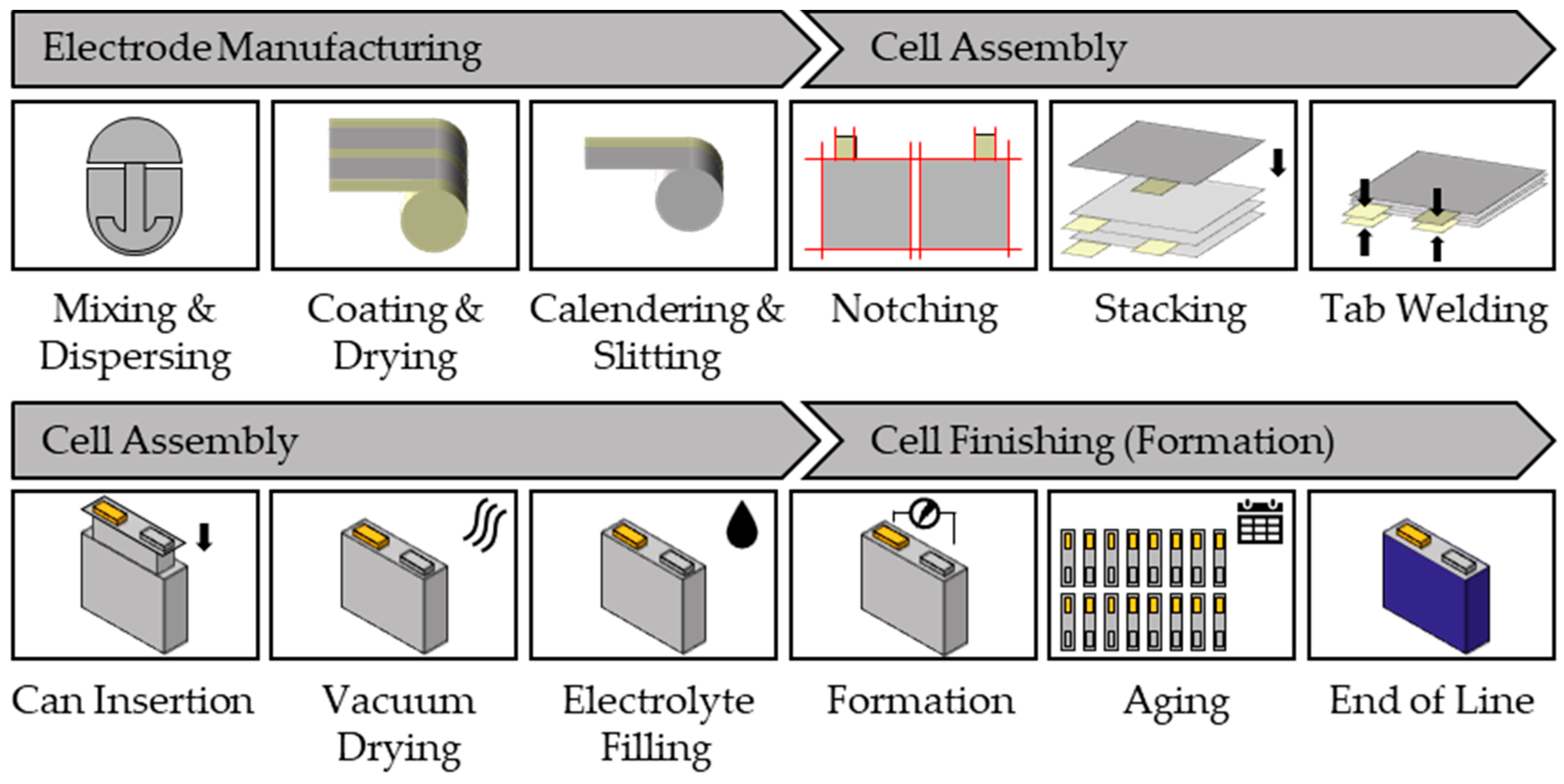
2. Manufacturing of Lithium-Ion Battery Cells

LIBs are electrochemical cells that convert chemical energy into electrical energy (and vice versa). They consist of negative and positive electrodes (anode and cathode, respectively), both of which are surrounded by the electrolyte and separated by a permeable polyolefin membrane (separator). An electrode consists of an electroactive material, as well as a binder material, which enables structural integrity while improving the interconnectivity within the electrode, adhesion to the current collector and the formation of the solid electrolyte interface (SEI) during the first battery cell cycles [9]. Lithium-ion battery cells are connected (either in series or in parallel) in battery modules. Then, battery modules with electrical, thermal and mechanical components are assembled into a battery pack. It should be noted that in this paper, either battery or the cell refers to a single LIB cell and neither to the module nor the battery pack (system).
This section first describes the production of LIBs according to the state-of-the-art from the perspective of series production. Then, three examples are used to illustrate the challenges of series production. In the next sections, the process of industrialization from lab to pilot to series production is explained and the possibilities and status of the use of artificial intelligence in battery cell production are discussed.

2.1. State-of-the-Art Manufacturing

Conventional processing of a lithium-ion battery cell consists of three steps: (1) electrode manufacturing, (2) cell assembly, and (3) cell finishing (formation) [8,10]. Although there are different cell formats, such as prismatic, cylindrical and pouch cells, manufacturing of these cells is similar but differs in the cell assembly step. The series production of prismatic cells is described below, and a schematic view for the manufacturing of a lithium-ion battery cell is given in Figure 1, as a reference.
Electrode manufacturing starts with the reception of the materials in a dry room (environment with controlled humidity, temperature, and pressure). Powder materials are supplied in bags: big bags for the active material and mostly paper bags for the binder and the conductive material. The bags are transported on pallets by roller conveyor and elevator from the warehouse to the feeding area on the second floor. After cleaning in an air shower in the dry room, the bags are moved to the feeding station. The big bags are lifted by crane. All the materials are automatically dosed according to the weight ratios specified in the recipe and conveyed to the first floor. Active material and a conductive agent are added directly to the electrode slurry mixer, whereas the binder powder is first fed to another mixer to prepare the binder solution. After dry mixing of the active material and conductive agent, the binder solution is added to make a slurry for electrode coating. Although different alternatives are being studied for its replacement, NMP (N-Methyl-2-pyrrolidone) is the most utilized cathode slurry solvent, while deionized water is used for the anode. A homogenous electrode slurry is prepared via planetary mixer, which applies high shear forces. During slurry mixing, viscosity is one of the key quality parameters to control the mixing process for high-quality electrode coating. After mixing, the slurry is degassed and buffered in a tank for a maximum of one to two days. Prior to coating, the slurry is pumped to another buffer tank placed nearby the coating stations. Tandem coaters are state-of-the-art in mass production. Here, the substrate film is unwound and rewound only once. Two continuous ovens are placed one above the other so that coating and drying of the second side can follow directly after coating and drying of the first side. Slot dies are used for the application in mass production. Screw pumps precisely convey the required amount of slurry from a third, smaller feed tank to the slot die to ensure the specified loading. The wet electrode web is transferred to a drying area to evaporate the solvent by heat supply. The drying area has different temperature zones (below solvent evaporation temperature) to avoid rapid drying and thermal stresses on the film. Rapid solvent removal will cause surface cracks on the film. The toxic NMP solvent is recovered by condensation and then followed by a distillation process. After coating, the electrode coil is transported to calendering. Calendering is a rolling process with at least two counter-rotating, heatable rolls. The application of pressure reduces the thickness, which increases the volumetric energy density, and since particles are pressed into the substrate film, the pressure improves the electrical conductivity. Before and/or after calendering, the electrode web is slit into several smaller electrode coils or trimmed according to the battery cell design (e.g., prismatic, cylindrical or pouch) by slitting with roller knives. Calendering and slitting are often integrated in one machine.
In electrode production, the quality of the individual production steps is crucial. Besides the formulation, the quality of the electrode is determined by its uniformity, porosity and freedom from defects. Defects in electrode production can lead to lithium plating, cell swelling, overheating and poor electrochemical performance. The production of the electrode is subject to a complicated mechanism, with a mixing of solid particles, binder, solvents and the dynamic processes of solvent evaporation and solidification of the slurry on the metal foil. To increase the output of electrode production, wide coaters (up to 1400 mm) are used, which are operated at a high speed (up to 100 m/min). This parameter setting can lead to high quality challenges. Defects that can occur during coating and subsequent curing include particle agglomeration in the coating slurry, air bubbles on the coating layer caused by insufficient degassing and buffering of the slurry, and partial flaking of the dried slurry or wavy edges due to insufficient viscosity. Further information on the industrial view of electrode production can be found in Sheng et al. [11].
The first step in the cell assembly is notching, where tabs are formed, or single sheets are cut out of the electrode web via laser cutting. The edge quality is examined regarding mechanical and thermal deformation. Moreover, the particle contamination on the electrode surface caused by cutting is checked. The next step is stacking the electrodes, where, although z-folding is currently widely used, it is being replaced by lamination stacking. Here, the separator is not folded around the electrodes but directly laminated on the anode, improving the speed and safety. The cell stack, commonly called a jelly roll, is then secured with tape to prevent the layers from slipping. The stacks are additionally heat-pressed and subsequently, the quality is determined by a thickness measurement. To determine the electrical insulation between the anodes and cathodes, an insulation test, the so-called Hi-Pot test, is performed. During the Hi-Pot test, high voltage direct current is applied to the cell stack to detect faults in the electrode production. The voltage applied is based on the cell design (e.g., number of electrodes in the jelly roll), generally in the range of 50–200 V. The electrical equivalent circuit diagram of the stack represents a circuit with a parallel resistor (R) and capacitor (C). The resistance of the stack is determined by the isolation of the separator. If a voltage is applied, the capacitance is changed. The voltage is applied for a time, for example, 5 s, and then the leakage current is measured (for example, less than 1 mA). If the leakage current is outside the tolerance, this indicates a defect. Typical defects are cracks in the separator, mismatching of electrode and separator or metallic contamination. After the Hi-Pot test, the anode and cathode tabs are bent, cut and joined together by ultrasonic welding. After this initial welding, protective tape is applied, and the cap is fixed by ultrasonic welding. The cap is also electrically insulated by tape, and another Hi-Pot test is performed. Next, the stack is wrapped with mylar tape for electrical insulation and pushed into the battery cell housing (can). To close the cell, the cap and can are laser-welded. After closing the battery cell, a helium test is performed as a leak test, and a Hi-Pot test is carried out again. Helium is a very volatile gas, and the pressure difference is used to verify the tightness of the battery cell. Before filling the electrolyte, the so-called baking, where vacuum drying is used to remove moisture and solvent residues, takes place. Battery cell baking and electrolyte filling are executed under clean (defined as the number of particles per m3) and dry room conditions, since eliminating moisture is important to avoid degradation of the electrolyte. The clean room classes correspond to ISO 7 or ISO 8 classes, and the dew points in these rooms are between −15 °C and −60 °C. The filling of the electrolyte is carried out with a dosing lance, in which the precision of the metering is important, so that the battery cell housing is not contaminated with the electrolyte. The electrolyte filled in should be distributed as homogeneously as possible and the quantity measured gravimetrically. After filling, the opening is temporarily closed, and the cell finishing begins.
Cell finishing (formation) starts with a high-temperature (HT) soaking step, where the wetting of the electrodes with electrolyte is enhanced in temperature chambers (approx. 45 °C). After this process, the batteries are transported to special racks and charged for the first time. During the first charge, the SEI is formed at the anode, which protects the anode from reactions with components of the electrolyte and influences the subsequent performance of the battery cell. Since this complex layer consists of different electrode and electrolyte decomposition products, the exact structure and formation of the SEI is still under investigation. During the initial charging process, gas is formed in larger cells and escapes under controlled conditions. After the first charging and the escape of the gas, a second or third electrolyte filling is carried out and the battery cell is finally sealed. Before closing with laser welding, the opening for the electrolyte filling is cleaned via laser cleaning. When the cell is finally sealed, a new leak test using helium is carried out and the final weight and dimensions are determined. The process for the wetting and formation of the cells takes 3–7 days [12]. In the following aging process, HT and RT (room temperature) resting takes place for continuous wetting, and then various current and voltage profiles are run through the battery cell. During aging, a process that can last for several weeks [12], the open-circuit voltage is measured to calculate the self-discharge rate, as elevated self-discharge values may indicate internal short circuits. In the final grading, the open-circuit voltage and internal resistance are measured. Afterwards, the battery cell housing is cleaned and wrapped with PET (polyethylene terephthalate) tape. Then, thickness measurements, together with dimensional and insulation tests are carried out. Finally, the cells are sorted according to their performance and thickness and transported to the outgoing warehouse. Cell finishing can account for up to 25% of factory floor space and requires a large amount of equipment, as each cell must go through this process [12].
After describing the manufacturing process of a lithium-ion battery cell, the methods of quality assurance will be briefly reported in this section. Quality generally indicates the extent to which a product meets the agreed requirements. The battery cell manufacturing process represents a quality chain in which the performance of both the product and the manufacturing process is examined. Methods of quality assurance in battery cell production have been demonstrated, for example, by Schnell and Reinhart, in which they proposed a quality gate concept for the complex production process [13]. Riexinger et al. also proposed a concept for the traceability of process parameters in the production of batteries, in which they addressed the measurement methods for individual process steps and the scope of testing [14]. Although numerous approaches and proposals for quality assurance have already been made, no standards have been established to date. This is due to the complexity of the manufacturing process (many process steps with intermediate products and different cycle times) and the different battery cell formats and designs (material combinations). The technical cleanliness of the production process plays a major role in the quality of the product. From the mass production manufacturer point of view, the cost of quality control (time to collect quality parameters and measuring equipment) must always be less than the cost of scrap rates. In addition, the effort toward quality assurance leads to higher quality products for which higher market prices can be achieved. To illustrate the process of quality assurance in industry, a comparison between the literature versus the industrial procedure is given using the example of the mixing and calendering process. Table 1 shows the quality parameters identified as important in the literature, as well as their measurement methods.
Table 1 shows a large number of quality parameters that can be recorded in battery cell production. In industrial practice, however, only a selection is monitored. This is because the parameters have already been validated during product and process development. Selected parameters in series production for mixing and calendering are shown in Table 2. A comparison of the parameters between Table 1 and Table 2 is facilitated by bold print.
Industrial manufacturing follows a systematic approach to quality assurance in which the methods, devices, frequency and scope (100% test vs. random sample) of the tests, etc., are defined in a control plan that combines in-line and laboratory testing. If quality deviations are found, the corresponding samples are subjected to a detailed laboratory analysis. Deviations in quality are processed according to quality management methods 8D or 5why. In the 8D method, a team is formed, the problem is described, and immediate action is taken to correct the error. In the event of a serious deviation, additionally, the 5why method can be used, in which the cause of the error is analyzed. The production parameter settings are adjusted until the specification values are restored. The products produced during this time are sorted according to the severity of the error.
In summary, the quality of the production of a lithium-ion battery cell is ensured by monitoring numerous parameters along the process chain. In series production, the approach is to measure only as many parameters as necessary to ensure the required product quality. The systematic application of quality management methods enables this approach. If quality is not assured, scrap is produced, and this is associated with high costs. The reason for this is that the cost of a battery cell is dominated by the cost of the materials, which accounts for around 75% of the manufacturing costs [13]. The share of material costs in manufacturing is not expected to fall in the next few years. On the contrary, material costs are expected to rise due to a shortage and high demand of raw materials [16]. In addition, the production of a battery consists of many individual steps, and it is necessary to achieve high quality in every production step and to produce little scrap. In a long process chain with, for example, 25 process steps and a yield of 99.5% each, the cumulative yield is just 88% [17]. This highlights the economic relevance of scrap minimization. Thus, in the next section, challenges in industrial battery cell manufacturing with special attention to scrap reduction will be discussed.

2.2. Challenges in Industrial Battery Cell Manufacturing

The basis for reducing scrap and, thus, lowering costs is mastering the process of cell production. The process of electrode production, including mixing, coating and calendering, belongs to the discipline of process engineering. Cell assembly with notching, stacking, filling, etc., is assigned to assembly technology. Cell finishing with charging of the battery to set the performance is covered by electrical engineering. All disciplines must work closely together to reduce production costs. The complexity of the battery manufacturing process, the lack of knowledge of the dependencies of product quality on process parameters and the lack of standards in quality assurance often lead to production over-engineering, high scrap rates and costly test series during industrialization [13]. In the next sections, selected examples from our expert experiences in series production will be presented, specifically, cases from the electrode, cell assembly and formation areas, based on which improvements in quality and a reduction of the scrap rates were obtained.
In the industrial process for electrode manufacturing, slot die coating is a state-of-the-art production process due to its high precision and controllable flow behavior. Compared to other technologies, slot die coating has the advantages of a high coating speed combined with even thickness of the coating layer. When using slot die coating, surface defects rarely occur and the scaling work from pilot to series is feasible. The hydrodynamic behavior of the slurry and the coating parameters can be coordinated. Nevertheless, in coating, large-scale trial and error tests must be carried out through the industrialization of the process to set the optimal process conditions. This process is time-consuming and expensive; the development of a new battery cell goes through several sample phases (refer Section 2.3), which take a total of 3 years from A-sample to D-sample. Once the product has been developed and industrialized, however, it takes about a month in electrode production to set the parameters of a new formulation. Therefore, more time must be spent on research and the establishment of a clear understanding of the relationship between the coating method and process parameters [18,19]. The selected example here shows how to proceed when a coating fault occurs in series production and what challenges still exist. The process chain of slot die coating, starting with mixing, and the challenge of setting the process parameters is not that simple. In serial production, it can be assumed that the process parameters are optimally set, and the slurry flowing into the slot die is homogeneously mixed and of good quality. Using filters (mesh and magnetic filters), foreign particles are removed, thus diminishing the presence of agglomerates. Despite the homogeneously mixed slurry, the filter system and the constant movement of the slurry through circulation, agglomerates can still appear on the slot die, leading to coating imperfections; when the slurry flows out of the slot die, the surface of the die can be irregularly wetted with slurry, thus resulting in the buildup of agglomerates. These agglomerates can block the outflow on the slot die and lead to a coating defect (Figure 2).
A defect in the coating directly causes high scrap costs since material costs are the main costs. The following calculation illustrates the costs that are incurred: two coating strips of 550 mm, coating speed 60 m/min, areal density of the electrode with 96 wt.% cathode active material (CAM) of 20 mg/m2, time for failure detection and correction of 30 s and price of LFP (lithium iron phosphate) of 20 USD/kg [19]. At such a coating speed and 30 s (the time needed to detect and correct the coating failure), and a coating width of 2 × 550 mm, approx. 30 m2 of electrode coating becomes unusable, meaning that with a load of 20 mg/cm2 with 96 wt.% CAM, approx. 5.76 kg of CAM were used in this area. At a price of 20 USD/kg for LFP, the scrap material cost is USD 115 for the single-layer coating. This example emphasizes the awareness on economic impact of scrap in electrode coating and how important it is to have a controllable and stable process.
The first measures carried out are the manual cleaning of the application tool at certain intervals, as well as the adjustment of the process parameters. The state of the art here is to first shut down the fault and, if necessary, stop production, and then to carry out a fault analysis with appropriate measures. In the following paragraphs, the procedures for investigation are explained and an overview of which scientific approaches are already available is provided.
To explain the wetting behavior of the slurry, it is worth looking at its thixotropic rheological behavior, meaning that the viscosity is conditioned by the shear stress. With increasing shear stress, the viscosity initially falls, and after the shear stress decreases, the viscosity recovers. The deviations in the wetting of the slurry at the downstream meniscus are explained by Xiaoyu Ding et al. with the formation of a vortex when slurry is applied [20]. Figure 3 shows schematically how the downstream meniscus vortices form when slurry is applied through the slot die.
The decisive quality-determining parameters for the slot die coating are the distance between the slot die and the foil, the gap of the slot die and its shim geometry. Due to possible agglomerate formation on the downstream meniscus of the slurry, attention should be paid to the other parameters. It can be assumed that the return of the slurry due to the formation of vortices leads to the different wetting of the slot die and the formation of agglomerates. (Figure 4)
In the following paragraphs, the potential influences on the quality of the coating due to the formation of agglomerates and possible solutions are summarized. When composing the slurry, the rheological behavior should be examined in detail and the thixotropy influence should be taken into account so that the line speed is set to match the shear rate and the runback of the slurry to the downstream meniscus (different wetting due to vortex formation) is prevented as far as possible. In addition, the influence of the slot die itself should be investigated in more detail [20]. The surfaces of the slot nozzle can be adapted to influence the flow behavior. For example, the downstream lip can be treated with a lyophobic surface (solvent–repellent) and the upstream nozzle with a lyophilic surface (solvent–affine) [21]. In this way, the position of the contact line can be precisely determined, avoiding the drying out of slurry and, thus, the formation of agglomerates due to an irregular formation of the meniscus. From the point of view of series production, carrying out further investigations and examining the entire system, starting with the mixing up to the slurry application, will be useful.
The next discussed industrial example is laser cutting, which, as part of the cell assembly process, is used for the pole tab production for subsequent contacting of the electrode sheets. This technology is state-of-the-art to produce pole tabs, as the heat input is low and the cut quality is high. The laser cut must be optimally adjusted in its process parameters for different material combinations, such as copper foil (uncoated and slurry-coated) and aluminum foil (uncoated, slurry-coated and ceramic-coated). While laser cutting for slurry-coated metal foils (anode and cathode) has already been scientifically investigated numerous times [22,23,24] and rarely leads to quality problems in series production, laser cutting of cathodes with a ceramic layer (insulation layer) next to the cathode coating edge can pose a challenge. For this reason, it is worth taking a look at the process parameters. Figure 5 shows the irregularities on the cutting edge of the ceramic-coated aluminum foil. When the ceramic material is melted by the laser, an irregular cutting burr is formed, which is partly below the tolerance width and partly above the tolerance width. The occurrence of irregular melting during laser cutting of the ceramic coating can lead to subsequent short circuits in the battery.
The laser cut is determined by numerous process parameters, such as laser energy, frequency of the laser pulse, the wavelength and polarization of the laser beam, process gas, orientation and distance of the nozzle to the foil. The first step in analyzing the irregular cutting edge of the ceramic coating on the aluminum foil is to determine the laser process parameters. One cause of the formation of burrs can be, for example, the wrong polarization of the laser beam, in which the processing direction of the cut is selected transversely to the direction of oscillation of the laser beam. If the polarization direction is instead in line with the processing direction, a smooth and burr-free cut is made. The main setting parameters in the industrial process are the speed (10–60 m/min), laser power (100–500 kHz), pulse width and the distance between the beam and the foil. Images taken with a light microscope of a section of aluminum foil with a ceramic coating show clear differences in the heat-affected zone and structure of the laser cut when the parameters are varied. In addition to the setting of the laser parameters, the reason for an irregular cutting edge can also be caused by other process parameters relating to the cut material. The material properties that influence the cut edge are the layer thickness and quality of the aluminum foil (e.g., rolling direction), the loading of the ceramic layer (mg/cm2) and the resulting layer thickness after drying, and the degree of compaction after calendering. In addition, the quality of the laser cut can be influenced by the different material properties, such as the different thermal conductivity and crystalline structures of aluminum and ceramic. In the industrial coating process, coating on both sides is also common. This can also influence the cutting edge if, for example, there are deviations in the layer thickness on the A and B sides. Empirically observed, a high layer thickness of the ceramic coating combined with a low degree of compaction during calendering leads to more irregular cutting edges of the pole tabs during laser cutting.
In summary, it can be said that it is important not only to examine the properties of the materials and individual processes, but also to look at the relevant parameters of series production. Research work on laser cutting in battery cell production has so far mostly focused on uncoated and slurry-coated foils and their cut edges. It would be interesting to expand research on cathodes with a ceramic strip next to the coating edge. This is also of interest regarding solid-state batteries. It must be emphasized that the coating of the films, whether slurry, ceramic or dry coating, is always a mixture of substances consisting of many additives. On the one hand, the additives serve to adjust the mechanical properties of the batteries so that the cycle load remains low, and on the other hand, the additives serve to increase the performance of the battery. To achieve developments and improvements here, materials science and process technology should work closely together.
The final example is related to the formation area, in which the first charging and testing of the battery cell, which can last several weeks, takes place. In this process step, a final decision is made whether the manufactured battery cell meets the requirements or whether it is scrap. Various quality parameters are measured for electrical characterization. Among other things, the open-circuit voltage (OCV), the internal resistance (IR) and the direct current internal resistance (DCIR) are measured. If the requirements are not met, rework is possible and the battery is re-submitted for HT or RT resting, for example. For process control and quality assurance, critical values and tolerance limits are defined for the electrical parameters to be measured. When measuring the electrical parameters, constant test conditions must be maintained. For example, cells that are exposed to different storage conditions (temperature deviation less than 5 k) show slight deviations in the open-circuit voltage (µV range) and self-discharge rate. Monitoring the temperature to correlate with test results is therefore recommended. If deviations in the open-circuit voltage measurement occur that lie outside the tolerance, a comprehensive analysis of the root cause is necessary. The measurement data are subject to a stochastic distribution. Errors correspond to outliers located at the edge of the distribution. In the event of an outlier detection, a broader data set is analyzed to identify correlations between outlier and production conditions (e.g., temperature). In this case, the batteries are removed from production and subjected to laboratory analysis. An example from series production is graphite powder residues on the separator. Due to deviation in the open-circuit voltage measurement, the cell was scrapped. After disassembly, the powder residues were visible during a visual inspection (Figure 6).
The particles were then analyzed via EDX to examine the source of contamination. The results can be seen in Table 3. The main element is carbon with 82.37 At%, which suggests that graphite particles are the cause of damage to the separator and short circuits.
The adhesion of graphite to the copper foil is the subject of many investigations. Graphite has poor adhesive properties because it is a soft and greasy material [25]. As an example, a primer layer is applied to increase the adhesion of the active material. Diehm et al. investigated the reduction of the binder in the anode slurry in order to increase the conductivity by reducing the proportion of the inactive components [26]. The adhesion could be increased by applying a carbon layer to the copper foil. Likewise, Lee and Oh increased the adhesion of the active material to the copper foil, as well as the performance of the cell by applying a graphene/polyvinylidene fluoride conductive adhesive layer [27]; however, applying a primer layer means an additional production step, and the costs that can be saved by reducing the scrap rate must be weighed against the effort required. Whether it is worth the effort to implement quality improvement measures and reduce the scrap rate is an individual company decision. The establishment of quality measures must be calculated as a business case and depends on, among other things, the cell chemistry, i.e., the raw material costs, personal costs, country-specific energy costs and supply chain. Regarding the example of a primer layer on the copper foil, it must be decided whether the coating is performed in-house, or a coated foil is purchased. If a coated foil is purchased, it is 30% more expensive than an uncoated one. The reduction in the scrap rate through this measure must then be compared with the costs for raw materials, energy, personnel, etc. Nevertheless, the application of a primer layer can be advantageous, as it creates a defined surface condition for the application of the slurry and the quality can be increased considerably. In addition to the possibility of using a primer to improve adhesion, the mechanical modification of the foil surface was also suggested by Babaiee et al. and Zhang et al. [28,29]. It was found that increased roughness improves adhesion, but partially impairs the electrochemical properties. Reducing the roughness by polishing the surface could improve the wetting of the slurry and improve conductivity and corrosion resistance.
The examples of surface treatment for examining adhesion and conductivity show that there is potential here to increase the quality of the film coating. Due to the individual slurry compositions of the manufacturers, however, tests must always be carried out. The quality assurance of the coating process should consist of several levels, such as a pre-process level, which ensures the quality of the materials used and the quality of the manufacturing equipment; a process-integrated level, which ensures the quality of the process and the surfaces; and a post-process level, which ensures the quality of the coated foil. The fact that the active material sometimes does not adhere to the foil as intended is therefore a problem and should be investigated further.
Graphite powder sometimes does not adhere properly, and the particles may result in contamination of the battery. The peel-off of the graphite powder from the layer can also be caused, for example, by the cutting process of the electrode. The graphite powder on the separator in Figure 6 slightly damaged it and led to micro-short circuits. A higher level of self-discharge was also found in these batteries compared to others. Extraordinarily, the particle residue only became visible in the formation by measuring the open-circuit voltage and self-discharge rate. Since quality check-up is accomplished in earlier stages of production steps (e.g., after the electrodes have been stacked and laminated), a Hi-Pot test was carried out. However, the damage to the separator did not cause any measurement deviations during the Hi-Pot test. It is therefore assumed that the production error became significant only when the electrolyte was filled in and the first charge was carried out. One explanation for this could be that the damage to the separator was caused by mechanical stress when charging the battery for the first time, since they are mechanically fixed in workpiece carriers. The mechanical tension counteracts the swelling of the electrodes and prevents the housing from warping. It is possible that due to the pressure that occurs in the battery during charging, the graphite particles were pressed deeper into the separator and permanently damaged it. Based on this explanation, it is possible that the graphite particles are only discovered when measuring the short-circuit current and the self-discharge in the formation. The required technical cleanliness in battery production must be also emphasized. There should be no particles that could damage the battery and lead to short circuits. From a quality point of view, it is interesting to carry out tests in which errors are introduced in different sections of the production process and to determine which method of quality measurement is suitable for error detection. It should also be noted that this error could only occur in serial production, since the mechanical fixation of batteries is handled less strictly in pilot lines and the focus there is placed on other process parameters.

2.3. Industrialization of Battery Cell Processing: From Lab to Pilot to Series Manufacturing

The development of new battery technologies starts with the lab scale where material compositions and properties are investigated. In pilot lines, batteries are usually produced semi-automatically, and studies of design and process parameters are carried out. The findings from this are the basis for industrial series production. Interdisciplinary co-operation between engineers, chemists and physicists is necessary to achieve scalability from pilot lines to series production. In the following section, it is shown how the process of product development up to the manufacture of the product is carried out. The product development in the production of lithium-ion battery cells, as well as in the production of the battery modules and packs takes place according to the established methods of the automotive industry. The APQP process (Advanced Product Quality Planning) is used, accompanied by an FMEA (Failure Mode and Effects Analysis) in all the process steps. The APQP process basically consists of a quotation phase, a product development phase and the serial production phase. The APQP process is part of the American QS9000 standard. The APQP process also combines the regulations of the international automotive industry IATF 16949, the German automotive industry VDA 6.1 and the French automotive industry EAQF [30].
The first phase in the development of a new product is the concept and planning phase. In this phase, product planning takes place based on customer requirements. In the development phase, product design and product development (PV = product verification), as well as process design and process development (DV = design verification) take place. Likewise, the technological feasibility of the product is clarified, and the technical risks are clarified at an expert level. At the end of the concept and planning phase, the business decision is made as to whether the project will be accepted or not. The second phase is the product and process confirmation phase. Here, project plans are defined, and the technology, process, quality goals and logistics concepts are planned according to the customer specifications. The third phase of the APQP process is the project approval phase, in which all previous plans are verified again and the final investment decision for the project is made. The fourth phase is the development phase, where A-, B- and C-samples are produced. This is a very important phase for the industrialization process: while only laboratory tests are carried out in the first concept and planning phase, here, the product is scaled up to pilot lines, test lines and, finally, up to series production. In the development phases for the A-, B- and C-samples, the manufactured products (samples) go through defined tests and evaluations. The A-samples, with sample volumes being mostly less than 100 batteries, less than 50 modules and less than 10 packs, are usually manufactured on a pilot line, and a simple function and performance test of the samples produced is performed. In the B-sample phase, a customer test and verification of the required product properties are carried out, and the construction of the product, the materials and substances used and the dimensions are examined in detail. Unlike A-samples, B-samples are manufactured on a larger test line or on the series production line with the purpose of freezing the product design. The C-samples are manufactured on the series production line, where they are checked in detail with regard to the customer specification (function, performance and quality), and the scaling to the specified product size of the customer takes place. In the C-sample phase, only slight design adjustments are made to the product, and by the end of this phase, the process design freeze and the process release occur. The fifth phase is the release phase, which represents the start of series production. After the SOP (start of production), approximately 3 months are planned as a ramp-up phase, in which the production capacity is successively increased. The D-samples, used for the approval of the product usage in the electric vehicle, are produced before the ramp-up phase. The Product Part Approval Process (PPAP) is the transition of the product into the delivery state of mass production of the product to the customer. SPC methods are used for quality monitoring and improvement in D-sample production, where the capability and stability of the production processes are increased. In addition, the findings from the series production are fed back, and tests are carried out with small series on the pilot line. The D-sample phase can be viewed as a pre-series or 0-series, as is common in the automotive industry before the SOP. In this phase, final adjustments are made to optimize the production process. After the SOP and the transition to series production, the customer’s knowledge of the product is of course integrated, and the product and processes can be continuously optimized.

2.4. Digital Twins for Battery Cell Manufacturing

A digital twin is a technical means to create a virtual entity of a physical operation in a digital way and to simulate, validate, predict and control the whole lifecycle process of the physical entity with the aid of historical and real-time data, as well as algorithm models [31]. In another words, a digital twin for battery cell manufacturing is the virtual replica of the physical battery manufacturing process (Figure 7). As a key technology and an important tool to improve efficiency, a digital twin can effectively play its role in model design, data collection, analysis and prediction, simulation and other aspects, promoting the digital industrialization and industry digitalization of lithium-ion battery cell manufacture and encouraging the integration and development of the industry’s digital and real economies [32]. A digital twin not only enables the simulation and testing of different manufacturing scenarios, allowing for rapid identification and resolution of potential issues before they occur, but also can be used to optimize production efficiency, reduce costs and improve quality control, ultimately resulting in a faster time to market for new battery chemistries. Tracing all the information from the process chain is enabled through a digital twin that links the machinery to data, but also through simulations to assess cascading effects. A possible scenario for the digital twin system of electrode and cell assembly processes is the integration of existing information and artificial intelligent systems in the manufacturing lines. Three-dimensional modeling, 3D simulation and digital twins of the processes are applied to monitor the whole production line on a digital twin platform. Real-time data from the operating manufacturing line are received. Then, the operation status of production line is visualized by retrieving the existing data [33]. One used-case example for a digital twin in battery manufacturing is SIMUBAT 4.0, which is the digital platform of the pilot manufacturing line of LIBs in the laboratory of Prof. Franco from CNRS [34]. Another example is the Tecnomatix Plant Simulation (PLM Solutions) using the digital twin of the standard battery manufacturing processes [35]. Both examples allow the users to explore the battery manufacturing processes in a virtual environment, paving the way for the validation of high-throughput and identifying possible bottlenecks.
The reduction and sorting of scrap in real production conditions needs fast action upon old and new data (i.e., live, retrainable models that can perform near-real-time decisions for optimization). For this, artificial intelligence (AI) tools and an orchestrator are required for data management. The AI orchestrator is an intention agnostic decision system used to optimize resource management and parameters and their cascading effects in the real manufacturing chain. This way, the orchestrator will inspect actions originating from existing tangible systems to provide insight and actionable recommendations for improving real manufacturing. AI orchestrators and tools have partially been developed, but have not yet been deployed to the production environment [36].

3. Advanced Manufacturing Technologies for LIB

Standard manufacturing process for LIB cells and the relevant standards and quality control measures, as well as the common challenges observed during manufacturing were discussed in Section 2. In Section 3, new processing technologies for battery cell manufacturing considering the current processing issues or as alternative solutions to enhance the manufacturing process with economically and environmentally friendly aspects are discussed. In this manner, dry-coating technology and 3D-printing, as well as anode prelithiation technology are summarized. The current development status, as well as the challenges that are faced for industrialization are discussed from an industrial perspective.

3.1. Dry-Coating Technology

Dry-coating technology, originated from the pharmaceutical industry and developed by Maxwell Technologies for electrode manufacture, enables manufacturers to attain defect-free electrodes with high coating loadings. The process technology is composed of dry powder mixing, dry coating of the powder mixture on the current collector, lamination and calendering, all executed in a solventless fashion. The solvent-free coating technology eliminates the use of toxic NMP needed in the classical wet processing, thus removing the drying step in the electrode coating, reducing both the production time, as well as the costs. This would provide high throughput electrode production with a minimal manufacturing footprint. Without the drying step, up to 47% of energy savings and a 19% reduction in manufacturing costs can be attained [37]. The scalability of the process in different cathode and anode chemistries, such as LFP, NMC (nickel–manganese–cobalt oxide), NCA (lithium–nickel–cobalt–aluminum oxide), LTO (lithium–titanium oxide) and silicon-based anodes, and a prolonged cycle-life in small- and large-pouch cell formats (≥10 Ah) have been reported by Maxwell [38]. Electrode configurations with thicknesses varying from 50 μm to 1 mm can be manufactured via dry coating, thus making it attractive for next generation battery electrodes, such as solid-state batteries (SSB)s. The definition of this battery concept, as well as its manufacturing methods are explained in Section 4. The electrode performance–property relationship, as well as the low manufacturing footprint aspects have taken the attention of the battery industry, and many research papers have been published summarizing the dry-processed electrodes and their performance [39,40,41,42,43,44].
In each process step, there are several challenges to be tackled. In the dry-mixing step, where the binder, active material and conductive agents are homogenously mixed by shear forces, agglomeration can happen due to excessive high energies. An inappropriate binder–mixer combination could also lead to inhomogeneities in the powder blend, which then would result in low-quality laminates during electrode coating. The dry-coating step, in which powder mix is turned into a dry film, is the key step of the process. The important coating methods are the Maxwell type, melt extrusion, direct calendering and dry-spray deposition [45] (see Figure 8). In Maxwell technology, a binder that exhibits considerable plasticity and forms fibers under shear force and thermal deformation is required to connect the electrode particles so that a self-supporting electrode film can be formed. PTFE (Polytetrafluoroethylene), which forms a homogenous network to support the free-standing films, is a widely applied binder for this method [25,44,46]. Direct calendering, which is very similar to Maxwell technology, has differences regarding the application of a powder mixture to the current collector. Dry-mixed powders are fed into the calender gap between two rollers rotating in opposite directions. Fibrilization of the binder takes place during direct coating on the current collector [41]. In melt extrusion method, powder mix compaction into a film under shear forces in which particles are connected via thermally deformed binder fibers takes place, with PEO (polyethylene oxide) and PP (polypropylene) as the most well-known binders for this process [45]. The dry-spray deposition method produces dry films from granulates of dry powder mixture as flowing particles. Hot rolling at the binder melting point is applied for binder consolidation on the particles [47]. A wide range of binder applications is possible, and PVDF is most preferred one. Since different coating methods require specific binder properties, the binder selection is the main challenge for the coating step. Although Maxwell’s is the most well-established method among the above-described ones, it is limited to PTFE, which also faces some challenges during processing, such as entanglement of the PTFE fibrils due to improper shear rates. Melt extrusion and dry-spraying methods enable a wider binder selection but the former requires accurate control of the shear rate, temperature and time for extrusion, while the latter presents difficulty controlling the electrode loading, thickness and homogeneity. In addition, higher temperatures (>80 °C) are required in the extrusion and spray methods for binder fluidity [37]; therefore, it makes achieving the energy-reduction targets (e.g., 47%) more difficult. As a sum-up for the large-scale application of dry-coating processes, the main challenges regarding powder mixing and dry-coating come from defining the proper process binder. A binder with a low melting point, high-voltage stability, high surface adhesion and good mechanical strength is required to attain defect-free, high loading (>20 mg/cm2) electrodes at lower processing temperatures (<80 °C). Likewise, reaching coating speeds in the same range as a wet-based process (60 m/min) with double-sided coating remains a challenge for dry-coating implementation. It should also be noted that the maturity level of this manufacturing technology is low, although its benefits for cost effectiveness and environmentally benign processing are apparent. Blue Solutions’ LMP (lithium metal polymer) technology, in which a dry extrusion process is applied for cathode and solid-polymer separator manufacturing, is the only example for scaled battery manufacturing in the market. There is still a path for either the industry or academia to develop a dry-coating technology to tackle all these challenges.

3.2. 3D-Printing

Additive manufacturing technologies, generally known as 3D-printing, enable manufacturers to fabricate objects with a complex geometry design. A wide range of materials is applicable for 3D-printing, such as polymers, metals and inorganic nanomaterials. Three-dimensional printing has shown great advantages in the fast prototyping of complex configurations with high accuracy while minimizing the manufacturing wastes; therefore, these technologies are extensively applied in the field of micro-electronics, microfluidics, aerospace and energy storage [48]. The process involves layer-by-layer deposition to produce 3D shapes monitored from a computer-aided design (CAD).
Three-dimensional printing has been applied to lithium-ion, lithium-metal and solid-state batteries to fabricate electrodes and solid electrolytes with precisely controlled structures and shapes in dimensions from nano- to macroscale. Indeed, via controlling the layer thicknesses, 3D-printing allows fitting more battery layers in the same battery space. At the same time, ionic resistance could be reduced via yielding short diffusion pathways. Therefore, the energy and power density of these batteries would be enhanced [49]. The printing technology approaches for lithium-ion and lithium-metal batteries are summarized in Figure 9. There is a great interest in the 3D-printing of lithium batteries in the research field [48,50,51,52,53]. There are different 3D-printing methods with different resolutions. Direct ink printing, which is a typical extrusion deposition technique of ink used as slurry, is capable of printing electrodes as low as 1 μm resolution. Aerosol jet printing, having approx. 10 μm resolution, has a very narrow printable material catalogue. Stereolithography, with the same resolution of 10 um, is suitable with relatively wider printable materials. With inkjet printing, it is possible to reach approx. 20 μm resolution. Fused deposition modelling, in which thermoplastic filaments are deposited in a layer-by-layer manner, is very suitable in macrolevel 3D-printing, thanks to their wider resolution range between 50 and 200 μm. If nano-sized resolution is needed, a viable method is template-assisted electrodeposition, which is capable of achieving resolutions from tens of nanometers up to tens of micrometers [48]. Table 4 summarizes the different 3D-printing methods and their resolution limits. In terms of the battery market, in 2020, Blackstone Technology announced the first functional batteries with thick printed electrodes (graphite anode and LFP cathode), where water-based binder systems were used in both layers. This technology also reduces process energy by 25%. Later, in 2021, mass-produced LFP batteries via 3D screen-printing technologies (in which a metal paste and a binder are pressed in a screen-printing process through a computer-generated mask, followed by a hardening step) were presented via press conference [54]. Blackstone also has a development program to produce solid-state batteries for sodium ion technology, which is planned to be used in Eurabus’ electric buses for performance validation and bring the batteries to the market by 2025 [55].
In 2021, Sakuu, a Californian start-up, also announced their first 3D-printed solid-state batteries. Sakuu has a proprietary process called 3D-printed Swift Print, which uses a Kavian printer and can use metal, polymer and glass materials in the same battery layer to produce SSB. The Swift Print battery technology includes binder jetting (where a metal or polymer powder is bound together with a fluid layer by layer) and metal material jetting (where a molten or metal slurry is deposited and hardened layer by layer) and relies on an integrated AI quality control and inspection before the layers are stacked together. More than one type of 3D-printing technology is used in parallel by the Kavian platform, which reduces the number of processing steps to half compared to the classical roll-to-roll process [56]. In 2022, Sakuu announced the sustainable and consistent printing SSBs, lithium-ion and lithium-metal battery designs with varying shapes in pilot scale. A volumetric energy density of 800 Wh/L was achieved in their lithium-metal batteries [57]. Recently, Sakuu also announced their upscaling plan: building a battery production line with a roll-to-roll process for lithium-metal batteries, followed by the Kavian platform for Swift Print SSB, 200 GWh annual production by 2030 [58]. Another 3D-printing company, Photocentric (UK), has been developing 3D-printers to manufacture SSBs based on resin 3D-printing using photopolymers. Photocentric has developed polymer electrolyte binders, along with anode and cathode powders into a printable photopolymer resin. Their technology is still in the R&D stage and the company has applied for a patent for it [56]. Among these three start-ups/companies, Blackstone has the highest maturity level in terms of technology and readiness level of the product to the market. Thanks to the reduction in material and energy costs (reduction in process time), flexibility in processing and mass customization, 3D-printing technologies could be a shiny offer for battery manufacturing in the coming years.
Figure 9. Three-dimensional printing technologies used in the production of lithium-ion and lithium-metal battery components. (Reprinted with permission from Ref. [59] 2023, Wiley VCH Verlag).
Batteries 09 00555 g009

3.3. Prelithiation Technology

Alternative electrode materials are always of primary interest to make batteries more environment-friendly and cost-competitive with a secured supply chain. Silicon, as an earth-abundant material, is receiving particular attention nowadays. It offers safe operation and high energy and power densities, making it a promising candidate to meet the ambitious market demands [60,61,62]. However, the major drawback that limits the widespread use of silicon is born from its low electrical conductivity and severe volume changes during cycling [63,64]. In addition, commonly used LiPF6-based organic electrolytes gradually degrade and form HF gases that lead unavoidable silicon etching during operation [65]. This will inevitably cause a sharp decay in the overall lifetime of the battery, affecting the energy and power density negatively. Moreover, many irreversible reactions that occur during the formation cycle cause a large amount of lithium-ion consumption (mainly from electrolytes), leading up to a 70% decrease in the initial coulombic efficiency (ICE) [66].
Prelithiation stands forward among other techniques with its unique nature to overcome the low ICE issue by simply providing an extra lithium reservoir to the system [67,68]. Prelithiation can be achieved via several ways, such as electrochemical deposition [69], mechanical [70], powder prelithiation [71] or chemical self-prelithiation [72]. Electrochemical deposition is an effective prelithiation technique that provides lithium to the anode via electrochemical deposition techniques. It can be performed in either a conventional three-electrode assembly [73] or by a hybridized approach known as open-circuit potential cycling, which combines conventional methods with short-circuit methods [74]. It is very convenient and easy-to-operate in lab-scale research; however, ICE improvement with this method is limited to the maximum Li deposited and is far from meeting large-scale requirements. Up to 84% of capacity retention is achievable via prelithiation with the electrodeposition technique in the NMC811|Si cells.
Mechanical prelithiation, on the other hand, offers an important advantage, as it has a high potential to adapt in the roll-to-roll processing lines. This technique makes it possible to apply to a wide portfolio of electrodes, and a high amount of lithium can be incorporated. Nevertheless, a high dependency on lithium resources is the primary drawback of this method.
Electrochemical deposition and mechanical prelithiation are the methods that can be applied directly to the electrode sheets, whereas it is also possible to adapt prelithiation technologies to the active materials, as it is the case for both powder prelithiation and chemical self-prelithiation methods. Powder prelithiation deals with lithium incorporation into the active materials, such as silicon, chemically. In the case of silicon anodes, LixSi alloys are formed, and electrode sheets made of these alloys show excellent structural stability. Powder prelithiation can provide ICE values close to the theoretical limit with the already reported data of 94% ICE. On the other hand, such alloys could be highly unstable in humid atmospheres, leading to explosion risks. Stability issues, accordingly, limit their widespread use in terms of safety while increasing the running costs. In this regard, self-prelithiation, described as providing the extra lithium inventory by means of self-driven chemical reactions happening during the battery operation, can offer improved safety. With the presence of nonpolar covalent solvents, lithium is extracted from the lithium metal sources thanks to the strong electrostatic forces, thus leading it to lithiate the anode active materials because of the self-driven chemical reactions caused by the huge potential difference. With this method, it is possible to reach higher ICE values up to 96% [75].
The most utilized anode in the industry is graphite. In a typical graphite anode electrode, the ICE is around 90%, meaning that 10% of the lithium is lost to SEI formation. As the industry is moving towards storing more energy in a cell, there is an evolution from a pure graphite anode towards mix of graphite and silicon oxide (SiOx) or graphite and silicon–carbon composites (Si/C). Anodes including SiOx are more developed and already established on the market (e.g., SVOLT). While commercially available SiOx can store around 1500 mAh/g, its ICE is dramatically reduced compared to a pure graphite anode with ICE below 80%. Low ICE clearly impacts not only the energy of the battery cell, but also the cost, as the lithium supply in an LIB comes from the more expensive cathode electrode. It is therefore of high importance to compensate for the initial loss to obtain a high-energy density battery, as well as optimize the costs. Currently, there are few potential directions for the upscaling of the pre-lithiation. The most straightforward and easiest way to industrialize relies on the addition of a pre-lithiation compound to the cathode electrode. Typically, a non-reversible high-capacity lithium compound, such as Li5FeO4, is added to the cathode slurry in low amounts (<5 wt.%) and provides extra lithium sourcing during the first charge. This method can partially compensate for the initial lithium loss experienced during SEI formation. However, while this is the easiest to industrialize, it is not the most optimal method to maximize energy density, as part of the cathode is replaced by the prelithiation compound, and the amount of lithium supplied by the cathode additive cannot provide sufficient lithium to the system. From the anode side, there are several prelithiation methods that are currently attracting an interest from the industrial manufacturing point of view.
  • Electrochemical prelithiation: Generally, lithium salt will be reduced on the anode electrode via an electrochemical bath. This method has excellent uniformity and has the benefit of having no lithium metal used. Moreover, the control over the lithiation process and the prelithiation uniformity is excellent. In addition, a great part of the SEI is already formed, thus reducing the gas generation during the first charge, which simplifies the formation protocol; however, during the reduction of the lithium compound, harmful gas will be formed and need further processing. Furthermore, the reactivity of the electrode after prelithiation is increased and further steps need to be implemented into the production process in order to control the safety risks.
  • Vacuum deposition of lithium metal onto the anode: Vaporized lithium metal is deposited in a vacuum chamber onto the anode electrode to form a lithium layer of generally <10 µm. The vacuum deposition technique is generally a slow and expensive method, making it incompatible with the current industrialization speed of lithium-ion battery manufacturing. Moreover, there are safety concerns due to the lithium metal used. As the electrode contains a thin lithium metal layer, its reactivity is increased, which complicates the further processing of the electrode. In addition, during the chamber cleaning process, lithium may ignite, causing a risk of fire. Finally, lithium being a sticky material, the rewinding of the electrode for further processing, as well as the electrode slitting becomes more difficult.
  • Direct coating of the electrode with stabilized lithium metal powder: The lithium metal powder is dispersed in a slurry and further coated or printed directly onto the anode electrode. The benefit of the process is that typical lithium-ion battery manufacturing speed (target: 80 m/min) can be achieved, and the amount of lithium deposited can be well controlled. Additionally, as the lithium powder is stabilized via a slurry, its reactivity is reduced. However, there are still some concerns regarding safety at large scale with the storage of stabilized lithium metal powder, as well as concerns about electrode reactivity after the coating of stabilized lithium metal powder. Furthermore, the current price of stabilized lithium metal powder is prohibitive for the industry and would result in an increase in cost.
To summarize, prelithiation has a large benefit in terms of energy density. It has also been shown to increase the cycle life, especially when large amounts of Si/C or SiOx are used. The electrochemical prelithiation method also has the benefit of creating most of the SEI outside the cell during the prelithiation stage, which further reduces gas generation during the formation process. Eventually, it is expected that the introduction of a large-scale compatible prelithiation process will further help in decreasing lithium-ion battery cell costs. However, currently, the addition of a prelithiation compound to the cathode remains the most straightforward and cheapest method, as there is no introduction of further steps to the production process.

4. Manufacturing of Solid-State Batteries

Solid-state batteries (SSBs), in which the conventional liquid electrolyte is replaced with a solid-electrolyte material (Figure 10), are regarded as promising candidates for next-generation batteries, and due to the fact that current LIBs have reached their limits in terms of energy densities (250 Wh/kg and ~600 Wh/L) with graphite anode and transition metal oxides [76], they will be considered as the battery alternative in the automotive industry in near future. SSBs enable reaching energy density values higher than 500 Wh/kg and 1500 Wh/L via replacing the anode with a lithium-metal anode [77]. In addition, switching the liquid electrolyte to solid material would prevent electrolyte leakage during damage, thus enhancing the battery safety. SSBs are classified based on the solid electrolyte material (inorganics, such as oxides and sulfides, and organic, such as self-standing polymers), as well as the state of the electrolyte: either a quasi/semi-solid-state (with a gel-like electrolyte) or all-solid-state (dry-solid electrolyte). Since this paper follows a chemistry-neutral approach, details about SSB chemistries will not be discussed further. Chemistry-specific information can be found in the published literature [76]. Instead, we aim to discuss here their fabrication process, comparing them with LIBs in terms of component production, challenges in production and current developments.
SSB manufacturing has three main steps: component manufacturing (composite cathode manufacturing, solid-electrolyte film (separator) manufacturing, anode manufacturing), battery cell assembly (cutting and staking of components) and battery cell finishing [78]. The steps can vary based on the solid-electrolyte material, as well as the anode concepts. These aspects have been discussed in several technical reports and scientific papers [76,79,80]. It should also be noted that sensitive dry room conditions (dew point levels less than −60 °C), especially during the processing of sulfide-based SSBs, and an inert atmosphere for the handling of lithium-metal anodes is important during the SSBs’ production process.

4.1. Component Manufacturing

Cathode composite manufacturing for SSBs initially utilized a standard electrode manufacturing route with slurry preparation and wet coating. The slurry preparation routes have remained similar; however, for a sulfide-solid electrolyte system, the solvent and binder materials had to be changed from NMP and PVDF to nonpolar solvents (e.g., toluol, xylene) and rubber binders (e.g., SBR (styrene butadiene rubber), SR (synthetic rubber)) due to the chemical interaction of sulfides with NMP [81] (in the cathode composite slurry). During slurry mixing, similar problems in the LIB, e.g., agglomeration of the conductive agent and an inhomogeneous distribution of active material, were observed, and similar approaches, such as changing the mixing order of the powder components and adapting the particle size of the CAM (cathode active material) were considered [82]. Doctor-blade coating directly onto the current collector takes place and the target electrode porosity is zero. However, this is not possible since a min. 1–2% porosity stays in the electrode after calendering, which comes from the binder elasticity. When the solid electrolyte material changes to oxides in the cathode composite, calendering would not be sufficient for attaining densified cathodes after coating and, therefore, sintering is required. However, although higher than 1000 °C is necessary, sintering temperatures are limited to 700–800 °C due to CAM degradation and side-reactions. Alternative processing technologies, such as melt infiltration of the electrolyte into the porous cathode, have been utilized [83] and confirmed for their applicability in upscale manufacturing. Among the electrolyte systems, polymer-based or gel-like electrolytes do not require additional processing steps or change in electrode components, like in oxides and sulfides, respectively. However, controlling the gel formation homogeneity during in situ gelification is still a challenge limiting the upscaled manufacturing.
Anode manufacturing methods differ depending on the anode selected in the cell design. If lithium metal is selected as the anode, it will generally be outsourced from lithium foil suppliers, and special attention must be paid to the foil thickness, which affects the total energy density of the battery cell. Although there is demand for thinner lithium foil, it is still very challenging to attain defect-free foils thinner than 30 μm [79], and a minimum of 20 µm can be attained via state-of the art foil processes [84]. Although some lithium foil suppliers can manufacture defect-free foils of less than 50 µm, there is a price increment with a reduced foil thickness [85,86]. Likewise, the surface quality and the lithium metal foil properties, which will impact the interface between the anode and solid electrolyte, must be controlled by surface treatment, such as thin film coatings. Those films should enable lithium-ion transport while providing a stable SEI; therefore oxide-based electrolyte materials (e.g., LATP (lithium–aluminum–titanium–phosphate) or LIPON (lithium–phosphorus–oxynitride)) are selected because of their stability against lithium metal. PolyPlus, together with SKI Innovations, recently developed a proprietary process to bond lithium metal (2 µm-thick) to a continuous monolithic glass electrolyte (20 µm-thick) [87,88]. SES Energy’s lithium-metal anode technology comprises a protective layer, a so-called composite anode coating to suppress dendrite growth [89]. For silicon-based anode systems, either pure silicon or a silicon–graphite (Si-Gr) blend, the anode manufacturing steps remains the same as in LIB production. Nevertheless, as with the cathode composite, the electrode recipe differs, and the solid electrolyte material is included during electrode manufacturing. Similarly, considerations on the binder–solvent selection must be contemplated when using sulfides. In terms of high silicon or pure silicon anodes, specialized binders withstanding high mechanical stress in the anode during charging may be required in the electrode recipe [76].
Solid-electrolyte film manufacturing (separator in LIB) is the most challenging step in SSB production. The type of solid electrolyte material determines the film processing and, eventually, the battery cell assembly process. Among them, attaining free-standing films without any defects and processing of oxide solid electrolyte films via wet processing technologies are the most challenging due to high-temperature densification requirements (sintering above 1000 °C). Indeed, this process step is energy-intensive and requires excess lithium and is therefore not cost effective and does not provide a high throughput process for large-scale manufacturing. Since oxide ceramic materials are very brittle compared to sulfide ceramics, handling of the free-standing film after production and during battery cell assembly process would not be straightforward like in LIB. For the industrial aspect, Quantumscape could be the only example in the direction of a product launch that uses a wet-based processing route, including continuous heat-treatment, to manufacture an oxide separator with their solid electrolyte material [90]. Although the company claims their process technology has a similar approach to multilayer ceramic capacitor production, details of the processing technology and key parameters remain hidden. For sulfide solid electrolytes, process challenges come from the binder–solvent-solid electrolyte material compatibility for wet processing. As mentioned before, sulfides are reactive to polar solvents like NMP; therefore, binder–solvent combinations remain limited [91]. Another challenge would be the dry room conditions for sulfides, which are sensitive against moisture. Initially, gloveboxes were settled in dry rooms due to the demanding dew point requirements (e.g., −60 °C) [92]. Solid Power and SVOLT, which have recently announced more than 10 Ah battery cells with a sulfide solid electrolyte, are proving the upscaling of the sulfide solid electrolyte film in pilot scale [93,94]. Polymer-based solid electrolyte films, on the other hand, have the most developed and matured processing among the others. Generally, dry or solvent-free processes such as extrusion are preferred instead of wet-based ones since these are well established and cost-effective for polymers. In this process, polymer material and lithium salt are mixed with an extruder and laminated onto the electrode, followed by the calendering process for densification and improved interfacial contact [37]. Indeed, the scalability and integration of the polymer solid electrolyte is straightforward and does not require an additional processing step or equipment investment, like oxides or sulfides. Blue Solutions’ LMP battery-entitling polymer separator is produced via an extrusion process and is commercially available in the market for electromobility applications.
The manufacturing of components in SSBs based on wet processing or classical film processing technologies have been summarized and discussed. However, the challenges named for composite electrodes or solid electrolyte separator films push the industry to develop alternative solutions together with the scientific community. One of the approaches is dry processes (either solventless or solvent-free), such as dry-coating via extrusion, dry printing or electrostatic spraying. Despite the limitations of the solvent–binder selection for compatibility with the sulfide solid electrolyte material, as well as the active material, dry-coating is becoming a widely investigated alternative processing technology for electrode and solid electrolyte film manufacturing [95,96]. Similar to dry processes in LIB, the components are mixed in the extruder and directly laminated onto the composite electrode or current collector during solid electrolyte film manufacturing and composite electrode manufacturing, respectively. However, the maturity level of the process is still low compared to wet-based technologies, and the coating speed is still the limiting factor for upscaling manufacturing. For oxides, extrusion or dry processing could be applicable in principle; however, since it does not entirely solve the densification of the separator, a sintering step is still required. Therefore, aerosol deposition technology has been proposed in which solid electrolyte particles are carried by a carrier gas (nitrogen or argon), together forming an aerosol, which is then transferred from an aerosol chamber into an evacuated deposition chamber, where it deposits onto the substrate (composite cathode or anode). Thanks to pressure differences between the aerosol and deposition chambers, dense layers (1–100 μm-thick) with strong adhesion can be attained while omitting the high-temperature heat treatment. However, technology has some limitations in terms of the deposition rates (10 mm3/min) [80] which could not compete with other manufacturing approaches (min. 1000 mm3/min), such as extrusion or doctor-blade coating for bulk separator manufacturing. Indeed, it is a very new technology and requires expensive equipment, limiting its usage in industrial scale processing in the near future.

4.2. Cell Assembly

The main differences between SSB and LIB for better cell assembly processes is electrolyte filling, battery cell formation and aging. The electrolyte filling step is removed, while formation and aging times are reduced in SSBs. The stacking step remains in the battery cell assembly; however, it differs in terms of the staking pressure and the stacking concepts (e.g., bipolar stacking). Higher stack pressures are required to maintain better contact between each unit cell. Bipolar stacking is a configuration for battery packs where all the mono cells are connected in series through one current collector contacting two electrodes without external connections [97]. The bipolar stacking concept is being considered due to its advantages over parallel stacking, such as better thermal and electrical properties, as well as reduction in the battery components in the cell (tabs and internal wiring), therefore reducing the weight and cost. This stacking concept can potentially increase the packing density and module level energy density [97,98]. Considering these benefits, Toyota has recently announced the bipolar stacked SSBs; Toyota has shown a 4-layer bipolar SSB for its EVs [99]. ProLogium is also using the bipolar stacking concept in their silicon-based SSBs with a hybrid solid electrolyte separator [100]. Aside from all these benefits, however, there are still challenges to be tackled: this stacking concept is limited to packs and system-building. For instance, BMS development is nontrivial and when defects occur at the cell level, detection and developing a solution are not as straightforward as in parallel stacking.
Another promising approach for the stacking of SSBs is an anode-free design, in which lithium is deposited onto the current collector during the first cycle of the battery [101], skipping the usage and the stacking of the lithium-metal foil during the assembly step and enabling milder dry room conditions in which to work. In addition, it does not require high CAPEX for equipment since, theoretically, already available equipment tooling and processing infrastructure can be used. It would also reduce the material cost coming from lithium metal, as well as solve the problem of finding a high-grade lithium foil with reduced thickness. Additionally, it also offers an important impact on lithium dependency, as it lowers the required lithium in the high-energy density lithium-metal batteries. With this cell design, the desired anode thickness can be achieved and the high stack pressure requirement issue, especially for oxide-based SSBs, can be solved. Many studies have been published based on the anode-free approach [102,103]. One of the challenges for this approach is to design the current collector, which is used as a substrate for Li-metal deposition, as well. Besides all these benefits, there are limited examples at the pilot scale and/or working towards industrialization in the market, e.g., QuantumScape and Sakuu, and SOP (start of production) by 2030 with the current battery performance is challenging.

4.3. Cell finishing

In comparison to classical LIB production, and since there is no electrolyte filling step, cell finishing is shorter in SSBs, meaning that no degassing is required during formation. In addition, the aging time is reduced because SEI formation is faster. It should be noted that for the SSB cells with a Li-metal anode, this step might be also skipped. In this sense, switching to SSB manufacturing has high potential to reduce the OPEX.
In Section 4, the manufacturing of SSBs was summarized while comparing with the process steps of LIB manufacturing, its challenges and current process development. Although SSB technology shows the higher potential to promise ambitious expectations (targets), the state of the art is not mature enough to move beyond prototypes. There is still a path to move towards the upscaling of SSB manufacturing and commercialization of the product to the market. The current limitations come not only from the challenges of upscaling and the applicability of the process, but also the availability of battery materials (e.g., sulfide-based solid electrolyte, thin lithium foil) on the large-scale in the market. Finally, a vast amount of information available both in the market and the academia on SSB technology is not compact; therefore, adaptation of the valuable data for upscaling and manufacturability is interrupted. A comprehensive study involving all players from academia to industry is necessary to tackle all these challenges.

5. Summary and Conclusions

In this paper, we delivered our expert opinion from the industry perspective for the manufacturing of lithium-ion batteries while considering daily manufacturing exercises and common challenges observed during production. In this regard, in Section 2, the industrial manufacturing targets to reduce the scrap rates and improve the processing quality due to high material costs (70% of productions costs are related to raw materials) were defined. The upscaling of battery cell manufacturing technology in the view of automotive standards was also explained. In addition to this, in Section 3, upcoming manufacturing technologies for the battery cell as possible solutions for environmentally safe, cost effective and high throughput process, and the requirements for industrialization were summarized. Finally, in Section 4, manufacturing of SSBs with a comparison to the state-of-the art manufacturing considering the current challenges and possible technologies as a solution were explained.
Key points should be highlighted from the industrial perspective, aiming to raise awareness among material and equipment manufacturers, as well as researchers/technology developers, on the requirements and expectations from the battery cell manufacturing perspective:
  • Promoting the understanding of process parameters and the associated product quality relationship is crucial to achieve a high throughput process.
  • Establishing (international) standards for battery manufacturing is paramount for reliable and reproducible product quality, enabling easy scalability from the lab to series production. Since battery production is a cost-intensive (material and energy costs) process, these standards will help to save time and money.
Battery manufacturing consists of many process steps and the development takes several years, beginning with the concept phase and the technical feasibility, through the sampling phases until SOP. There are various players involved in the battery manufacturing processes, from researchers to product responsibility and quality control. Timely, close collaboration and interaction among these parties is of vital relevance.
Thanks to its outstanding properties and approval by various OEMs (original equipment manufacturer), LIBs are foreseen to still be on the market in the next decade. Because of that, there is still a self-driven ambition to test the limits of LIB technology by battery manufacturers. Cost, energy density, reproducibility, modular battery design and manufacturing are key indicators to determine the future of the battery manufacturing industry. In this regard, novel material design, together with next-generation manufacturing technologies, including solvent-free manufacturing, will help in making the process cost-effective and environmentally friendly.
Technology is evolving towards Industry 4.0; therefore, it is inevitable for battery manufacturers to get their share. Three-dimensional printing, an indispensable member of Industry 4.0, has already started to play a role in today’s manufacturing. It provides a unique advantage on reproducible manufacturing, although the overall cost burden is relatively high. However, there is a huge benefit in considering the partial integration of 3D printing tools during the specific stages of battery manufacturing.
Growing interests in digital twins will enable battery manufacturers to shift from one battery technology to another without giving extra effort to OPEX. There is lot research going on the upcoming battery technologies, but many developments are still only in the A-sample stage due to the significant risk for upscaling. This flexibility will help battery manufacturers to adapt their production facilities to next-generation battery technologies, making them ready for upscaled or series production.

Author Contributions

Conceptualization, A.Ö.A.; methodology and writing—original draft preparation, A.Ö.A., T.G., F.Z., K.B.D., L.U. and F.Z.; writing—review and editing, supervision, M.B. and L.U. All authors have read and agreed to the published version of the manuscript.

Funding

This research did not receive any specific grant from funding agencies in the public, commercial or not-for-profit sectors.

Data Availability Statement

Not applicable.

Acknowledgments

The authors would like to thank to Lohit Mallohalli from SVOLT Energy Europe R&D Center for the fruitful discussions regarding digital twins and artificial intelligence for battery manufacturing and usage. Special thanks to Batuhan Senol from SVOLT Europe Operations team for his contribution to the reproduction of the schematics. The authors also would like to thank Zhu Stark from SVOLT Energy Technology Operations and Processing for the fruitful discussion regarding battery manufacturing challenges.

Conflicts of Interest

The authors declare that the study was conducted in the absence of any commercial or financial relationships that could be construed as a potential conflicts of interest.

References

  1. Lal, A.; You, F. Will Reshoring Manufacturing of Advanced Electric Vehicle Battery Support Renewable Energy Transition and Climate Targets? Sci. Adv. 2023, 9, eadg6740. [Google Scholar] [CrossRef]
  2. Baazouzi, S.; Feistel, N.; Wanner, J.; Landwehr, I.; Fill, A.; Birke, K.P. Design, Properties, and Manufacturing of Cylindrical Li-Ion Battery Cells—A Generic Overview. Batteries 2023, 9, 309. [Google Scholar] [CrossRef]
  3. Patoux, S.; Sannier, L.; Lignier, H.; Reynier, Y.; Bourbon, C.; Jouanneau, S.; Le Cras, F.; Martinet, S. High Voltage Nickel Manganese Spinel Oxides for Li-Ion Batteries. Electrochim. Acta 2008, 53, 4137–4145. [Google Scholar] [CrossRef]
  4. Ryu, H.H.; Park, K.J.; Yoon, C.S.; Sun, Y.K. Capacity Fading of Ni-Rich Li[NixCoyMn1-x-y]O2 (0.6 ≤ x ≤ 0.95) Cathodes for High-Energy-Density Lithium-Ion Batteries: Bulk or Surface Degradation? Chem. Mater. 2018, 30, 1155–1163. [Google Scholar] [CrossRef]
  5. Yang, H.; Bang, H.; Amine, K.; Prakash, J. Investigations of the Exothermic Reactions of Natural Graphite Anode for Li-Ion Batteries during Thermal Runaway. J. Electrochem. Soc. 2005, 152, A73. [Google Scholar] [CrossRef]
  6. Salah, M.; Murphy, P.; Hall, C.; Francis, C.; Kerr, R.; Fabretto, M. Pure Silicon Thin-Film Anodes for Lithium-Ion Batteries: A Review. J. Power Sources 2019, 414, 48–67. [Google Scholar] [CrossRef]
  7. Terranova, M.L.; Orlanducci, S.; Tamburri, E.; Guglielmotti, V.; Rossi, M. Si/C Hybrid Nanostructures for Li-Ion Anodes: An Overview. J. Power Sources 2014, 246, 167–177. [Google Scholar] [CrossRef]
  8. Liu, Y.; Zhang, R.; Wang, J.; Wang, Y. Current and Future Lithium-Ion Battery Manufacturing. iScience 2021, 24, 102332. [Google Scholar] [CrossRef] [PubMed]
  9. Bresser, D.; Paillard, E.; Passerini, S. Lithium-Ion Batteries (LIBs) for Medium- and Large-Scale Energy Storage: In Advances in Batteries for Medium and Large-Scale Energy Storage; Elsevier: Amsterdam, The Netherlands, 2015; pp. 125–211. ISBN 9781782420224. [Google Scholar]
  10. Li, J.; Fleetwood, J.; Hawley, W.B.; Kays, W. From Materials to Cell: State-of-the-Art and Prospective Technologies for Lithium-Ion Battery Electrode Processing. Chem. Rev. 2022, 122, 903–956. [Google Scholar] [CrossRef]
  11. Smyrek, P.; Pfleging, W. Processing and Manufacturing of Electrodes for Lithium-Ion Batteries; Li, J., Jin, C., Eds.; Institution of Engineering and Technology: London, UK, 2023; ISBN 9781839536694. [Google Scholar]
  12. Wood, D.L.; Li, J.; An, S.J. Formation Challenges of Lithium-Ion Battery Manufacturing. Joule 2019, 3, 2884–2888. [Google Scholar] [CrossRef]
  13. Schnell, J.; Reinhart, G. Quality Management for Battery Production: A Quality Gate Concept. Procedia CIRP 2016, 57, 568–573. [Google Scholar] [CrossRef]
  14. Riexinger, G.; Doppler, J.P.; Haar, C.; Trierweiler, M.; Buss, A.; Schöbel, K.; Ensling, D.; Bauernhansl, T. Integration of Traceability Systems in Battery Production. Procedia CIRP 2020, 93, 125–130. [Google Scholar] [CrossRef]
  15. Maiser, E.; Michaelis, S.; Müller, D.; Kampker, A.; Deutskens, C.; Heimes, H.; Sarovic, N.; Klusmann, N.; Thielmann, A.; Sauer, A. Roadmap Battery Production Equipment 2030; Update; VDMA: Frankfurt, Germany, 2014; pp. 1–63. [Google Scholar]
  16. Lithium-Ion Battery Pack Prices Rise for First Time to an Average of $151/KWh. Available online: https://about.bnef.com/blog/lithium-ion-battery-pack-prices-rise-for-first-time-to-an-average-of-151-kwh/ (accessed on 26 October 2023).
  17. Kwade, A.; Haselrieder, W.; Leithoff, R.; Modlinger, A.; Dietrich, F.; Droeder, K. Current Status and Challenges for Automotive Battery Production Technologies. Nat. Energy 2018, 3, 290–300. [Google Scholar] [CrossRef]
  18. Liu, H.; Cheng, X.; Chong, Y.; Yuan, H.; Huang, J.-Q.; Zhang, Q. Advanced Electrode Processing of Lithium Ion Batteries: A Review of Powder Technology in Battery Fabrication. Particuology 2021, 57, 56–71. [Google Scholar] [CrossRef]
  19. Bernhart, W. The Lithium-Ion (EV) Battery Market and Supply Chain–Market Drivers and Emerging Supply Chain Risks; Roland Berger: Munich, Germany, 2022. [Google Scholar]
  20. Ding, X.; Liu, J.; Harris, T.A.L. A Review of the Operating Limits in Slot Die Coating Processes. AIChE J. 2016, 62, 2508–2524. [Google Scholar] [CrossRef]
  21. Lin, C.-F.; Wang, B.-K.; Tiu, C.; Liu, T.-J. On the Pinning of Downstream Meniscus for Slot Die Coating. Adv. Polym. Technol. 2013, 32, E249–E257. [Google Scholar] [CrossRef]
  22. Kronthaler, M.R.; Schloegl, F.; Kurfer, J.; Wiedenmann, R.; Zaeh, M.F.; Reinhart, G. Laser Cutting in the Production of Lithium Ion Cells. Phys. Procedia 2012, 39, 213–224. [Google Scholar] [CrossRef]
  23. Lutey, A.H.A.; Fortunato, A.; Carmignato, S.; Ascari, A.; Liverani, E.; Guerrini, G. Quality and Productivity Considerations for Laser Cutting of LiFePO4 and LiNiMnCoO2 Battery Electrodes. Procedia CIRP 2016, 42, 433–438. [Google Scholar] [CrossRef]
  24. Pfleging, W. A Review of Laser Electrode Processing for Development and Manufacturing of Lithium-Ion Batteries. Nanophotonics 2017, 7, 549–573. [Google Scholar] [CrossRef]
  25. Du, Z.; Dunlap, R.A.; Obrovac, M.N. High Energy Density Calendered Si Alloy/Graphite Anodes. J. Electrochem. Soc. 2014, 161, A1698–A1705. [Google Scholar] [CrossRef]
  26. Diehm, R.; Müller, M.; Burger, D.; Kumberg, J.; Spiegel, S.; Bauer, W.; Scharfer, P.; Schabel, W. High-Speed Coating of Primer Layer for Li-Ion Battery Electrodes by Using Slot-Die Coating. Energy Technol. 2020, 8, 2000259. [Google Scholar] [CrossRef]
  27. Lee, S.; Oh, E.-S. Performance Enhancement of a Lithium Ion Battery by Incorporation of a Graphene/Polyvinylidene Fluoride Conductive Adhesive Layer between the Current Collector and the Active Material Layer. J. Power Sources 2013, 244, 721–725. [Google Scholar] [CrossRef]
  28. Babaiee, M.; Zarei-Jelyani, M.; Baktashian, S.; Eqra, R. Surface Modification of Copper Current Collector to Improve the Mechanical and Electrochemical Properties of Graphite Anode in Lithium-Ion Battery. J. Renew. Energy Environ. 2022, 9, 63–69. [Google Scholar] [CrossRef]
  29. Zhang, J.; Zuo, D.; Pei, X.; Mu, C.; Chen, K.; Chen, Q.; Hou, G.; Tang, Y. Effects of Electrolytic Copper Foil Roughness on Lithium-Ion Battery Performance. Metals 2022, 12, 2110. [Google Scholar] [CrossRef]
  30. Laskurain, I.; Arana, G.; Heras-Saizarbitoria, I. Adopting ISO/TS 16949 and IATF 16949 standards: An exploratory and preliminary study. In ISO 9001, ISO 14001, and New Management Standards, 1st ed.; Heras-Saizarbitoria, I., Ed.; Springer: Cham, Switzerland, 2018; Volume 3, pp. 131–143. [Google Scholar]
  31. Zanotto, F.M.; Dominguez, D.Z.; Ayerbe, E.; Boyano, I.; Burmeister, C.; Duquesnoy, M.; Eisentraeger, M.; Montaño, J.F.; Gallo-Bueno, A.; Gold, L.; et al. Data Specifications for Battery Manufacturing Digitalization: Current Status, Challenges, and Opportunities. Batter. Supercaps 2022, 5, e202200224. [Google Scholar] [CrossRef]
  32. Eddy, J.; Pfeiffer, A.; van de Staaij, J. Recharging Economies: The EV-Battery Manufacturing Outlook for Europe. Available online: https://www.mckinsey.com/industries/oil-and-gas/our-insights/recharging-economies-the-ev-battery-manufacturing-outlook-for-europe (accessed on 27 August 2023).
  33. Ayerbe, E.; Berecibar, M.; Clark, S.; Franco, A.A.; Ruhland, J. Digitalization of Battery Manufacturing: Current Status, Challenges, and Opportunities. Adv. Energy Mater. 2022, 12, 2102696. [Google Scholar] [CrossRef]
  34. Franco, A.A.; Loup-Escande, E.; Loiseaux, G.; Chotard, J.; Zapata-Dominguez, D.; Ciger, J.; Leclere, A.; Denisart, L.; Lelong, R. From Battery Manufacturing to Smart Grids: Towards a Metaverse for the Energy Sciences**. Batter. Supercaps 2023, 6, e202200369. [Google Scholar] [CrossRef]
  35. Cards PLM Solutions Plant Simulation—Digital Twin of a Battery Production. Available online: https://www.youtube.com/watch?v=piwslwafan0& (accessed on 30 October 2023).
  36. Amici, J.; Asinari, P.; Ayerbe, E.; Barboux, P.; Bayle-Guillemaud, P.; Behm, R.J.; Berecibar, M.; Berg, E.; Bhowmik, A.; Bodoardo, S.; et al. A Roadmap for Transforming Research to Invent the Batteries of the Future Designed within the European Large Scale Research Initiative BATTERY 2030+. Adv. Energy Mater. 2022, 12, 2102785. [Google Scholar] [CrossRef]
  37. Lu, Y.; Zhao, C.Z.; Yuan, H.; Hu, J.K.; Huang, J.Q.; Zhang, Q. Dry Electrode Technology, the Rising Star in Solid-State Battery Industrialization. Matter 2022, 5, 876–898. [Google Scholar] [CrossRef]
  38. Duong, H.; Shin, J.; Yudi, Y. Dry Electrode Coating Technology. In Proceedings of the 48th Power Sources Conference, Denver, CO, USA, 11–14 June 2018; Volume 3-1, pp. 34–37. [Google Scholar]
  39. Schälicke, G.; Landwehr, I.; Dinter, A.; Pettinger, K.H.; Haselrieder, W.; Kwade, A. Solvent-Free Manufacturing of Electrodes for Lithium-Ion Batteries via Electrostatic Coating. Energy Technol. 2020, 8, 1900309. [Google Scholar] [CrossRef]
  40. Liu, J.; Ludwig, B.; Liu, Y.; Pan, H.; Wang, Y. Strengthening the Electrodes for Li-Ion Batteries with a Porous Adhesive Interlayer through Dry-Spraying Manufacturing. ACS Appl. Mater. Interfaces 2019, 11, 25081–25089. [Google Scholar] [CrossRef] [PubMed]
  41. Degen, F.; Kratzig, O. Future in Battery Production: An Extensive Benchmarking of Novel Production Technologies as Guidance for Decision Making in Engineering. IEEE Trans. Eng. Manag. 2022. early access. [Google Scholar] [CrossRef]
  42. Ludwig, B.; Liu, J.; Liu, Y.; Zheng, Z.; Wang, Y.; Pan, H. Simulation of Micro/Nanopowder Mixing Characteristics for Dry Spray Additive Manufacturing of Li-Ion Battery Electrodes. J. Micro Nano-Manuf. 2017, 5, 1700570. [Google Scholar] [CrossRef]
  43. Zhang, Y.; Huld, F.; Lu, S.; Jektvik, C.; Lou, F.; Yu, Z. Revisiting Polytetrafluorethylene Binder for Solvent-Free Lithium-Ion Battery Anode Fabrication. Batteries 2022, 8, 57. [Google Scholar] [CrossRef]
  44. Yao, W.; Chouchane, M.; Li, W.; Bai, S.; Liu, Z.; Li, L.; Chen, A.X.; Sayahpour, B.; Shimizu, R.; Raghavendran, G.; et al. A 5 V-Class Cobalt-Free Battery Cathode with High Loading Enabled by Dry Coating. Energy Environ. Sci. 2023, 16, 1620–1630. [Google Scholar] [CrossRef]
  45. Zhang, Y.; Lu, S.; Wang, Z.; Volkov, V.; Lou, F.; Yu, Z. Recent Technology Development in Solvent-Free Electrode Fabrication for Lithium-Ion Batteries. Renew. Sustain. Energy Rev. 2023, 183, 113515. [Google Scholar] [CrossRef]
  46. Mitchell, P.; Zhong, L.; Xi, X. Recyclable Dry Particle Based Adhesive Electrode and Methods of Making Same. U.S. Patent 7,342,770, 11 March 2008. [Google Scholar]
  47. Park, D.W.; Cañas, N.A.; Wagner, N.; Friedrich, K.A. Novel Solvent-Free Direct Coating Process for Battery Electrodes and Their Electrochemical Performance. J. Power Sources 2016, 306, 758–763. [Google Scholar] [CrossRef]
  48. Mo, F.; Guo, B.; Liu, Q.; Ling, W.; Liang, G.; Chen, L.; Yu, S.; Wei, J. Additive Manufacturing for Advanced Rechargeable Lithium Batteries: A Mini Review. Front. Energy Res. 2022, 10, 986985. [Google Scholar] [CrossRef]
  49. Pei, M.; Shi, H.; Yao, F.; Liang, S.; Xu, Z.; Pei, X.; Wang, S.; Hu, Y. 3D Printing of Advanced Lithium Batteries: A Designing Strategy of Electrode/Electrolyte Architectures. J. Mater. Chem. A 2021, 9, 25237–25257. [Google Scholar] [CrossRef]
  50. Pinilla, S.; Ryan, S.; Mckeon, L.; Coelho, J.; Nicolosi, V. Towards 3D Printed Batteries: A Comparative Study between Electrode Fabrication Processes. ECS Meet. Abstr. 2020, MA2020-02, 497. [Google Scholar] [CrossRef]
  51. Choi, K.H.; Ahn, D.B.; Lee, S.Y. Current Status and Challenges in Printed Batteries: Toward Form Factor-Free, Monolithic Integrated Power Sources. ACS Energy Lett. 2018, 3, 220–236. [Google Scholar] [CrossRef]
  52. Beydaghi, H.; Abouali, S.; Thorat, S.B.; Del Rio Castillo, A.E.; Bellani, S.; Lauciello, S.; Gentiluomo, S.; Pellegrini, V.; Bonaccorso, F. 3D Printed Silicon-Few Layer Graphene Anode for Advanced Li-Ion Batteries. RSC Adv. 2021, 11, 35051–35060. [Google Scholar] [CrossRef]
  53. Maurel, A.; Grugeon, S.; Armand, M.; Fleutot, B.; Courty, M.; Prashantha, K.; Davoisne, C.; Tortajada, H.; Panier, S.; Dupont, L. Overview on Lithium-Ion Battery 3D-Printing By Means of Material Extrusion. ECS Meet. Abstr. 2020, MA2020-02, 3690. [Google Scholar] [CrossRef]
  54. Blackstone Resources AG Company History. Available online: https://www.blackstoneresources.ch/en/about-blackstone/company-history/ (accessed on 25 August 2023).
  55. Blackstone Announces Plans for 3D Printed Sodium-Ion Batteries. Available online: https://www.electrive.com/2022/03/28/blackstone-announces-plans-for-3d-printed-sodium-ion-batteries/ (accessed on 25 August 2023).
  56. Schwaar, C. Additive Manufacturing for Batteries of the Future: Will 3D Printing Transform Battery Making? Available online: https://www.forbes.com/sites/carolynschwaar/2023/01/30/additive-manufacturing-for-batteries-of-the-future-will-3d-printing-transform-battery-making (accessed on 25 August 2023).
  57. Sakuu Unveils 3D Printed Batteries for Licensing. Available online: https://www.electrive.com/2023/05/25/sakuu-unveils-3d-printed-batteries-for-licensing/ (accessed on 25 August 2023).
  58. Sakuu Selects Porsche Consulting for Design of Commercial-Scale Battery Manufacturing Plants. Available online: https://www.sakuu.com/news/sakuu-selects-porsche-consulting-for-design-of-com (accessed on 25 August 2023).
  59. Pang, Y.; Cao, Y.; Chu, Y.; Liu, M.; Snyder, K.; MacKenzie, D.; Cao, C. Additive Manufacturing of Batteries. Adv. Funct. Mater. 2020, 30, 1906244. [Google Scholar] [CrossRef]
  60. Larcher, D.; Beattie, S.; Morcrette, M.; Edström, K.; Jumas, J.C.; Tarascon, J.M. Recent Findings and Prospects in the Field of Pure Metals as Negative Electrodes for Li-Ion Batteries. J. Mater. Chem. 2007, 17, 3759–3772. [Google Scholar] [CrossRef]
  61. Kasavajjula, U.; Wang, C.; Appleby, A.J. Nano- and Bulk-Silicon-Based Insertion Anodes for Lithium-Ion Secondary Cells. J. Power Sources 2007, 163, 1003–1039. [Google Scholar] [CrossRef]
  62. Takamura, T.; Uehara, M.; Suzuki, J.; Sekine, K.; Tamura, K. High Capacity and Long Cycle Life Silicon Anode for Li-Ion Battery. J. Power Sources 2006, 158, 1401–1404. [Google Scholar] [CrossRef]
  63. Ng, S.H.; Wang, J.; Wexler, D.; Chew, S.Y.; Liu, H.K. Amorphous Carbon-Coated Silicon Nanocomposites: A Low-Temperature Synthesis via Spray Pyrolysis and Their Application as High-Capacity Anodes for Lithium-Ion Batteries. J. Phys. Chem. C 2007, 111, 11131–11138. [Google Scholar] [CrossRef]
  64. Khomenko, V.G.; Barsukov, V.Z.; Doninger, J.E.; Barsukov, I.V. Lithium-Ion Batteries Based on Carbon-Silicon-Graphite Composite Anodes. J. Power Sources 2007, 165, 598–608. [Google Scholar] [CrossRef]
  65. Yin, Y.; Wan, L.; Guo, Y. Silicon-Based Nanomaterials for Lithium-Ion Batteries. Chin. Sci. Bull. 2012, 57, 4104–4110. [Google Scholar] [CrossRef]
  66. Zhu, B.; Liu, G.; Lv, G.; Mu, Y.; Zhao, Y.; Wang, Y.; Li, X.; Yao, P.; Deng, Y.; Cui, Y. Minimized Lithium Trapping by Isovalent Isomorphism for High Initial Coulombic Efficiency of Silicon Anodes. Sci. Adv. 2019, 5, 2101565. [Google Scholar] [CrossRef] [PubMed]
  67. Zhan, R.; Wang, X.; Chen, Z.; Seh, Z.W.; Wang, L.; Sun, Y. Promises and Challenges of the Practical Implementation of Prelithiation in Lithium-Ion Batteries. Adv. Energy Mater. 2021, 11, 2101565. [Google Scholar] [CrossRef]
  68. Jin, L.; Shen, C.; Wu, Q.; Shellikeri, A.; Zheng, J.; Zhang, C.; Zheng, J.P. Pre-lithiation Strategies for Next-generation Practical Lithium-ion Batteries. Adv. Sci. 2021, 8, 2005031. [Google Scholar] [CrossRef] [PubMed]
  69. Winter, M.; Besenhard, J.O. Electrochemical Lithiation of Tin and Tin-Based Intermetallics and Composites. Electrochim. Acta 1999, 45, 31–50. [Google Scholar] [CrossRef]
  70. Xu, H.; Li, S.; Chen, X.; Zhang, C.; Liu, W.; Fan, H.; Yu, Y.; Huang, Y.; Li, J. Sn-Alloy Foil Electrode with Mechanical Prelithiation: Full-Cell Performance up to 200 Cycles. Adv. Energy Mater. 2019, 9, 1902150. [Google Scholar] [CrossRef]
  71. Esen, E.; Mohrhardt, M.; Lennartz, P.; de Meatza, I.; Schmuck, M.; Winter, M.; Paillard, E. Effect of Prelithiation with Passivated Lithium Metal Powder on Passivation Films on High-Energy NMC-811 and SiCx Electrodes. Mater. Today Chem. 2023, 30, 101587. [Google Scholar] [CrossRef]
  72. Li, Y.; Zhang, Q.; Zhang, K.; Yang, F. Coupling Effects of Self-Limiting Lithiation, Reaction Front Evolution and Free Volume Evolution on Chemical Stress in Amorphous Wire-Based Electrodes. J. Power Sources 2020, 457, 228016. [Google Scholar] [CrossRef]
  73. Eguchi, T.; Sugawara, R.; Abe, Y.; Tomioka, M.; Kumagai, S. Impact of Full Prelithiation of Si-Based Anodes on the Rate and Cycle Performance of Li-Ion Capacitors. Batteries 2022, 8, 49. [Google Scholar] [CrossRef]
  74. Sun, X.; Wang, P.; An, Y.; Zhang, X.; Zheng, S.; Wang, K.; Ma, Y. A Fast and Scalable Pre-Lithiation Approach for Practical Large-Capacity Lithium-Ion Capacitors. J. Electrochem. Soc. 2021, 168, 110540. [Google Scholar] [CrossRef]
  75. Guo, J.; Dong, D.; Wang, J.; Liu, D.; Yu, X.; Zheng, Y.; Wen, Z.; Lei, W.; Deng, Y.; Wang, J.; et al. Silicon-Based Lithium Ion Battery Systems: State-of-the-Art from Half and Full Cell Viewpoint. Adv. Funct. Mater. 2021, 31, 2102546. [Google Scholar] [CrossRef]
  76. Schmaltz, T.; Wicke, T.; Weymann, L.; Voß, P.; Neef, C.; Thielmann, A. Solid-State Battery Roadmap 2035+; Fraunhofer ISI: Karlsruhe, Germany, 2022. [Google Scholar]
  77. Albertus, P.; Anandan, V.; Ban, C.; Balsara, N.; Belharouak, I.; Buettner-Garrett, J.; Chen, Z.; Daniel, C.; Doeff, M.; Dudney, N.J.; et al. Challenges for and Pathways toward Li-Metal-Based All-Solid-State Batteries. ACS Energy Lett. 2021, 6, 1399–1404. [Google Scholar] [CrossRef]
  78. Heimes, H.H. Production of All-Solid-State Battery Cells; PEM der RWTH Aachen University: Aachen, Germany, 2018; ISBN 3947920040. [Google Scholar]
  79. Schnell, J.; Günther, T.; Knoche, T.; Vieider, C.; Köhler, L.; Just, A.; Keller, M.; Passerini, S.; Reinhart, G. All-Solid-State Lithium-Ion and Lithium Metal Batteries—Paving the Way to Large-Scale Production. J. Power Sources 2018, 382, 160–175. [Google Scholar] [CrossRef]
  80. Hatzell, K.B.; Zheng, Y. Prospects on Large-Scale Manufacturing of Solid State Batteries. MRS Energy Sustain. 2021, 8, 33–39. [Google Scholar] [CrossRef]
  81. Cao, D.; Zhao, Y.; Sun, X.; Natan, A.; Wang, Y.; Xiang, P.; Wang, W.; Zhu, H. Processing Strategies to Improve Cell-Level Energy Density of Metal Sulfide Electrolyte-Based All-Solid-State Li Metal Batteries and Beyond. ACS Energy Lett. 2020, 5, 3468–3489. [Google Scholar] [CrossRef]
  82. Komura, S. Method of Producing Cathode Slurry, Cathode and All-Solid-State Battery, and Cathode and All-Solid-State Battery. U.S. Patent 20200287208, 10 September 2020. pp. 1–18. [Google Scholar]
  83. Xiao, Y.; Turcheniuk, K.; Narla, A.; Song, A.Y.; Ren, X.; Magasinski, A.; Jain, A.; Huang, S.; Lee, H.; Yushin, G. Electrolyte Melt Infiltration for Scalable Manufacturing of Inorganic All-Solid-State Lithium-Ion Batteries. Nat. Mater. 2021, 20, 984–990. [Google Scholar] [CrossRef]
  84. Yasunami, S.; Honjo, H.; Honjo, K.; Kimio, S. Manufacture of Lithium Metal Foil or Lithium Alloy Foil. Japan Patent JPH1058007A, 3 March 1998. [Google Scholar]
  85. Schmuch, R.; Wagner, R.; Hörpel, G.; Placke, T.; Winter, M. Performance and Cost of Materials for Lithium-Based Rechargeable Automotive Batteries. Nat. Energy 2018, 3, 267–278. [Google Scholar] [CrossRef]
  86. Frith, J.T.; Lacey, M.J.; Ulissi, U. A Non-Academic Perspective on the Future of Lithium-Based Batteries. Nat. Commun. 2023, 14, 420. [Google Scholar] [CrossRef]
  87. McMahan, S. SK Innovation to Use PolyPlus’ Glass Separator Tech for Li Battery Development. Available online: https://eepower.com/news/sk-innovation-to-use-polyplus-glass-separator-tech-on-development-of-li-battery-anodes/ (accessed on 25 August 2023).
  88. The World’s First Glass Protected Li Metal Battery. Available online: https://polyplus.com/glass-protected-lithium-battery/ (accessed on 25 August 2023).
  89. SES Corporate Overview. Available online: https://investors.ses.ai/events-and-presentations/presentations/default.aspx (accessed on 30 October 2023).
  90. Ceramics 101: The QuantumScape Separator in Context. Available online: https://www.quantumscape.com/resources/blog/ceramics-101-the-quantumscape-separator-in-context/ (accessed on 25 August 2023).
  91. Oh, D.Y.; Nam, Y.J.; Park, K.H.; Jung, S.H.; Kim, K.T.; Ha, A.R.; Jung, Y.S. Slurry-Fabricable Li + -Conductive Polymeric Binders for Practical All-Solid-State Lithium-Ion Batteries Enabled by Solvate Ionic Liquids. Adv. Energy Mater. 2019, 9, 1802927. [Google Scholar] [CrossRef]
  92. Chen, Y.-T.; Marple, M.A.T.; Tan, D.H.S.; Ham, S.-Y.; Sayahpour, B.; Li, W.-K.; Yang, H.; Lee, J.B.; Hah, H.J.; Wu, E.A. Investigating Dry Room Compatibility of Sulfide Solid-State Electrolytes for Scalable Manufacturing. J. Mater. Chem. A 2022, 10, 7155–7164. [Google Scholar] [CrossRef]
  93. Prawitz, S. Svolt Stellt Feststoffbatteriezellen Mit Einer Ladung von 20 Ah Her. Available online: https://www.automobil-industrie.vogel.de/svolt-stellt-feststoffbatteriezellen-mit-einer-ladung-von-20-ah-her-a-35b73f0558deb7616ed35e805c684987/ (accessed on 25 August 2023).
  94. Solid Power Meets All 2021 Milestones with Production of 20Ah Silicon EV Cells. Available online: https://www.solidpowerbattery.com/solid-power-meets-all-2021-milestones/ (accessed on 25 August 2023).
  95. Tan, D.H.S.; Chen, Y.T.; Yang, H.; Bao, W.; Sreenarayanan, B.; Doux, J.M.; Li, W.; Lu, B.; Ham, S.Y.; Sayahpour, B.; et al. Carbon-Free High-Loading Silicon Anodes Enabled by Sulfide Solid Electrolytes. Science 2021, 373, 1494–1499. [Google Scholar] [CrossRef]
  96. Cangaz, S.; Hippauf, F.; Reuter, F.S.; Doerfler, S.; Abendroth, T.; Althues, H.; Kaskel, S. Enabling High-Energy Solid-State Batteries with Stable Anode Interphase by the Use of Columnar Silicon Anodes. Adv. Energy Mater. 2020, 10, 2001320. [Google Scholar] [CrossRef]
  97. Tan, D.H.S.; Meng, Y.S.; Jang, J. Scaling up High-Energy-Density Sulfidic Solid-State Batteries: A Lab-to-Pilot Perspective. Joule 2022, 6, 1755–1769. [Google Scholar] [CrossRef]
  98. Xu, L.; Lu, Y.; Zhao, C.Z.; Yuan, H.; Zhu, G.L.; Hou, L.P.; Zhang, Q.; Huang, J.Q. Toward the Scale-Up of Solid-State Lithium Metal Batteries: The Gaps between Lab-Level Cells and Practical Large-Format Batteries. Adv. Energy Mater. 2021, 11, 2002360. [Google Scholar] [CrossRef]
  99. Toyota to Launch All-New Aqua. Available online: https://global.toyota/en/newsroom/toyota/35584064.html#bipolar (accessed on 25 August 2023).
  100. Prologium Products. Available online: https://prologium.com/products/ (accessed on 30 October 2023).
  101. Pal, S.; Zhang, X.; Babu, B.; Lin, X.; Wang, J.; Vlad, A. Materials, Electrodes and Electrolytes Advances for next-Generation Lithium-Based Anode-Free Batteries. Oxf. Open Mater. Sci. 2022, 2, itac005. [Google Scholar] [CrossRef]
  102. Heubner, C.; Maletti, S.; Auer, H.; Hüttl, J.; Voigt, K.; Lohrberg, O.; Nikolowski, K.; Partsch, M.; Michaelis, A. From Lithium-metal toward Anode-free Solid-state Batteries: Current Developments, Issues, and Challenges. Adv. Funct. Mater. 2021, 31, 2106608. [Google Scholar] [CrossRef]
  103. Wang, M.J.; Carmona, E.; Gupta, A.; Albertus, P.; Sakamoto, J. Enabling “Lithium-Free” Manufacturing of Pure Lithium Metal Solid-State Batteries through in Situ Plating. Nat. Commun. 2020, 11, 5201, Erratum in Nat. Commun. 2020, 11, 6400.. [Google Scholar] [CrossRef]
Figure 1. Production steps in lithium-ion battery cell manufacturing summarizing electrode manufacturing, cell assembly and cell finishing (formation) based on prismatic cell format.
Batteries 09 00555 g001
Figure 2. Coating defect in the electrode due to particle agglomeration [SVOLT image].
Batteries 09 00555 g002
Figure 3. Formation of vortices in the slurry at the downstream meniscus (reproduced from [20]).
Batteries 09 00555 g003
Figure 4. Formation of vortices leads to different wetting of the slot die with a high (A) and a low (B) meniscus (reproduced from [21]).
Batteries 09 00555 g004
Figure 5. Irregular cutting edge of ceramic coating by laser cutting. [SVOLT Image].
Batteries 09 00555 g005
Figure 6. Residues of graphite powder on the separator [SVOLT Image].
Batteries 09 00555 g006
Figure 7. Schematics showing how digital twin of real battery manufacturing enables information transfer. (Reproduced from [36]).
Batteries 09 00555 g007
Figure 8. Schematic presentation for the manufacturing steps for dry electrode coating and three dry-coating technologies (reproduced from [37]).
Batteries 09 00555 g008
Figure 10. Representative images for lithium-ion battery (LIB) and solid-state battery cells.
Batteries 09 00555 g010
Table 1. Quality parameters and measurement methods according to literature recommendations [15].
Process StepImportant Quality ParametersMeasurement Methods
(In-Line and Laboratory Analysis)
MixingPurityElemental analysis ICP
Suspension densityPycnometer
Solid contentSolid balance, moisture determination
HomogeneityGrindometer
ViscosityRheometer
Agglomerate sizeLaser diffraction particle size analyzer
Particle size distributionSEM microscopy
TemperaturePT100 thermometer
pH valuepH measurement
Surface tensionTensiometry
Electric conductivityimpedance measurement
CalenderingLayer thickness, density and porosityLaser triangulation
Surface roughnessReflectometer
Surface finishCamera
Weight distributionArea mass scanner
Pore size distributionHg porosimeter
AdhesionTensile testing machine
Table 2. Process parameters and quality parameters using the example of mixing and calendering from an industrial perspective. [SVOLT Data].
Control ParametersMeasured Parameters
Raw materialRaw material environment (temperature and humidity)
Weighting of components (active materials, binders, etc.)
Monitoring of filters as initial condition for following processes
Workshop environmentMonitoring of the clean room class; for example, ISO 8
Monitoring of the dew point
Monitoring of temperature
Pressure control (vacuum environment)
Process parameters: mixingEquipment setting for stirring (speed control)
Control of the standing time
Process temperature
Quality parameters: slurrySolid content
Viscosity
Homogeneity
Particle size distribution
Examine for metal particles
Examine for bubbles and agglomeration
Process parameters: calenderingRoller temperature monitoring
Roller pressure monitoring
Roller speed monitoring
Quality parameters: calenderingElectrode foil tension monitoring
Verifying the dimensions
Layer thickness
Surface resistivity
Table 3. EDX measurement results [SVOLT data].
ElementAtomic Ratio/At%
C82.37
O10.14
F6.79
Na0.02
Al0.01
P0.59
S0.06
Ca0.01
Fe0.01
Total100.00
Table 4. Three-dimensional printing technologies and their resolution limits for manufacturing.
3D-Printing Method Resolution
Template-assisted electrodeposition 50 nm
Direct ink printing 50 nm–1 μm
Aerosol jet printing 10 μm
Stereolithography 10 μm
Inkjet printing 20 μm
Fused deposition 50–200 μm
Disclaimer/Publisher’s Note: The statements, opinions and data contained in all publications are solely those of the individual author(s) and contributor(s) and not of MDPI and/or the editor(s). MDPI and/or the editor(s) disclaim responsibility for any injury to people or property resulting from any ideas, methods, instructions or products referred to in the content.

