Review

A Review of Sodium-Metal Chloride Batteries: Materials and Cell Design

by
Salvatore Gianluca Leonardi
,
Mario Samperi
,
Leone Frusteri
,
Vincenzo Antonucci
and
Claudia D’Urso
*
National Research Council (CNR), Institute for Advanced Energy Technologies “Nicola Giordano” (ITAE), Via S. Lucia sopra Contesse, 5, 98126 Messina, Italy
*
Author to whom correspondence should be addressed.
Batteries 2023, 9(11), 524; https://doi.org/10.3390/batteries9110524
Submission received: 18 September 2023 / Revised: 9 October 2023 / Accepted: 18 October 2023 / Published: 24 October 2023
(This article belongs to the Special Issue Recent Progress in Energy Storage Materials and Devices)

Abstract

:
The widespread electrification of various sectors is triggering a strong demand for new energy storage systems with low environmental impact and using abundant raw materials. Batteries employing elemental sodium could offer significant advantages, as the use of a naturally abundant element such as sodium is strategic to satisfy the increasing demand. Currently, lithium-ion batteries represent the most popular energy storage technology, owing to their tunable performance for various applications. However, where large energy storage systems are required, the use of expensive lithium-ion batteries could result disadvantageous. On the other hand, high-temperature sodium batteries represent a promising technology due to their theoretical high specific energies, high energy efficiency, long life and safety. Therefore, driven by the current market demand and the awareness of the potential that still needs to be exploited, research interest in high-temperature sodium batteries has regained great attention. This review aims to highlight the most recent developments on this topic, focusing on actual and prospective active materials used in sodium-metal chloride batteries. In particular, alternative formulations to conventional nickel cathodes and advanced ceramic electrolytes are discussed, referring to the current research challenges centered on cost reduction, lowering of the operating temperature and performance improvement. Moreover, a comprehensive overview on commercial tubular cell design and prototypal planar design is presented, highlighting advantages and limitations based on the analysis of research papers, patents and technical documents.

Graphical Abstract

1. Introduction

The extensive use of lithium-ion batteries in electric vehicles, electronic devices and stationary environments is triggering a rush to hoard raw materials by battery manufacturers for their own deployment. Consequently, since these materials are not sufficiently abundant, there is a risk that the demand will exceed the supply, leading to a sharp increase in the cost of batteries. Energy storage devices based on elemental sodium instead of lithium could offer considerable advantages in covering the expected high demand for different applications since the use of a naturally abundant element such as sodium is strategic [1]. Sodium is inexpensive and has a very attractive redox potential (E° (Na+/Na) = −2.71 V vs. SHE), which is only about 0.3 V lower than Li+/Li (3 V vs. SHE) [2]. Accordingly, sodium-based rechargeable electrochemical cells represent an attractive choice for energy storage systems [3,4]. They can be categorized into two different systems: room-temperature sodium batteries with organic electrolytes and high-temperature batteries with solid electrolytes [5]. Only the high-temperature sodium-sulfur (Na-S) and sodium-metal chloride (Na-MeCl2) batteries, also known as sodium-beta-alumina batteries due to the solid ceramic electrolyte used as the separator, have emerged commercially in recent decades [6]. Although these two technologies have a different electrochemistry, the basic configuration and operation are similar. A sodium-sulfur battery employs a molten sodium anode and a S/Na2Sx as the cathode. In contrast, sodium-metal chloride batteries are still based on a molten sodium anode, but solid metal halides (NiCl2, FeCl2, CuCl2, ZnCl2, etc.) are used as cathode materials. ZEBRA is a common name for the sodium-metal chloride battery system, originally from Zeolite Battery Research Africa and later the Zero Emission Battery Research Activity project, which was aimed at the development of sodium-metal halide batteries in the 1970s. To date, ZEBRA batteries are among the most promising technologies for large-scale energy storage applications because of their high theoretical specific energies, high energy efficiencies, long lifetime and safety. Indeed, current commercial products have been widely tested in the grid and integrated with wind and solar energy in Japan, France and the USA [7]. These were also indicated as a promising technology for other applications, including the electric propulsion of surface ships, submarines and road vehicles [8,9].
A ZEBRA cell consists of a metal sodium electrode, a chlorinated metal electrode surrounded by a molten salt electrolyte, and a solid electrolyte, which electrically separates the anodic and cathodic compartments (Figure 1). Different components such as current collectors, sealing materials, external cases and different ancillary parts necessary to provide the practical operation of the system complete the cell assembly [10].
Nickel chloride (NiCl2) is the most representative metal halide constituting the active cathode materials of the current commercial ZEBRA batteries, making them also known as sodium-nickel chloride (Na-NiCl2) batteries. Iron chloride (FeCl2) is used as the secondary active phase, molten sodium tetrachloroaluminate (NaAlCl4) acts as a secondary electrolyte to facilitate the movement of the Na+ ions, and a small amount of other additives completes the composition of the cathode [10,11]. The separator employed is a β″-alumina ceramic that provides a Na+ conductivity higher than 0.2 S·cm−1 at 300 °C [6]. The typical operational temperature of ZEBRA batteries has to be 270–350 °C in order to ensure sufficiently fast kinetics for the reaction at the positive electrode and enough Na+ conductivity of the ceramic electrolyte [12]. The main redox reaction occurring in a ZEBRA battery is given in Equation (1):
2NaCl + Ni → NiCl2 + 2Na (E0 = 2.58 V at 300 °C)
Compared to most diffused lithium-ion batteries (Li-ion), which have a favorable higher cell potential (3.2–3.6 V), a Na-NiCl2 battery has just a slightly lower energy density of 100–120 Wh kg−1 against the 75–250 Wh kg−1 of a Li-ion battery, but a comparable power density of 150–200 W kg−1 [13]. However, the most interesting feature, which makes a Na-NiCl2 battery particularly attractive, is its intrinsic safety. Within specific limits, over-discharge is a reversible reaction, and a small amount of over-charge may only degrade the performance. Only a significant over-charge or over-discharge can result in cell failure without creating hazardous situations. In both cases, failure is always caused by a β″-alumina fracture without any hazard. The combination of electrical performance and safety characteristics makes Na-NiCl2 batteries suitable for different applications. In particular, they have been proven highly effective in terms of low risk and operating performance, in different grid services including load levelling, voltage regulation, frequency regulation, time shifting and the power fluctuation mitigation of renewable energy sources in high-voltage networks [14,15]. These batteries have also found widespread use as backup power, proving an effective solution for high energy storage in telecom installations [16,17]. Moreover, thanks to the high recyclability of the constituent materials, NiCl2 batteries have been able to decrease environmental impacts for different uses [18,19]. Since the operating temperature is consistently above ambient temperature, the internal temperature regulation is marginally influenced by external conditions, making the performance of Na-NiCl2 batteries almost independent from environmental conditions, with negligible self-discharge due to heater consumption and without the need for active cooling [20].
Beyond many merits of ZEBRA batteries, the high operating temperature represents the bottleneck of this technology, which still faces several challenges to further improve performance and cost control to promote the industrial chain [21,22]. Indeed, the high operating temperature is the cause of some technical issues responsible for the relatively high costs and performance degradation. In particular, NaAlCl4 is corrosive at the working temperature, and unique casing materials and sealing technologies are necessary [23,24]. High temperature is also detrimental to the stability of active materials. In this regard, the thermally enhanced growth of both Ni and NaCl particles at the cathode is one of the most crucial factors degrading the Na-NiCl2 battery performance. The larger the particles of active ingredients contained in the cathode, the less the active surface area is available for electrochemical reaction. Therefore, particle growth can lead to an increase in cell polarization arising from the reduced active area. A higher current density, higher state of charge (SOC) and lower Ni/NaCl ratio are the main parameters that result in rapid Ni particle growth [25,26]. The modification of Ni particles’ surface with a sulfur layer has been found to prevent their growth, thus reducing degradation during cycling [27]. However, the formation of less conductive layers on the Ni particles’ surface can limit the mass transfer of the non-porous electrode, causing the disconnection of the electron paths between active materials and the current collector, eventually limiting the total capacity of the cell. Since the structural properties of Ni particles strongly affects the cell performance, the initial morphology of cathode materials should be retained during battery operation for both a high charge capacity and excellent cyclic retention [28]. The excessive dissolution of NiCl2 in a NalCl4 melt induced by high temperature is another issue affecting the battery life. A high concentration of Ni2+ in the melt could exchange with the Na+ ions of the β″-alumina, resulting in the degradation of the solid electrolyte, hence increasing the resistance of the cell [29]. Chemical additives such as NaBr, NaI and sulfur, which are used to stabilize the morphology of the Ni/NiCl2 electrode, reducing the solubility of the NiCl2 in the NaCl-saturated NaAlCl4 melt, effectively hinder the ion exchange in the β″-alumina electrolyte, increasing the cycle life of the battery [30].
One of the most significant efforts of current research activities in developing new ZEBRA batteries aims at the reduction in the operating temperature. However, this goal faces several challenges. For instance, classical sodium-metal chloride batteries utilize NaAlCl4 as a secondary electrolyte, which has a melting point of 157 °C. In addition, it exhibits an ionic conductivity of 0.4 and 0.7 S·cm−1 at 200 and 300 °C [31]; therefore, it is more efficient at higher temperatures. In this regard, novel secondary electrolytes with improved ionic conductivity and sufficiently wide electrochemical windows at reduced temperatures can be a solution to reduce the operating temperature of Na-NiCl2 batteries [32]. Another challenge arising from the reduction in the operating temperature is the wettability of the solid electrolyte with metallic sodium. This is related to the existence of an oxide film on the metal surface that impedes the transfer of sodium through the interface with the electrolyte. Different approaches to overcome this problem have been proposed. The most common solutions are carbon or PbO coatings and vacuum treatments to remove adsorbed moisture on surface. However, these techniques still appear ineffective at lower temperatures, particularly below 200 °C [33,34].
Solid electrolytes with high Na ion conductivity are key materials for the performance improvement of sodium-metal halide batteries while operating at low temperatures. Although in the past few decades, signs of progress have been made in the development of advanced ceramic electrolytes [35], the low ionic conductivity of this material at low temperatures represents a critical issue for battery operation in this condition. Nevertheless, Na-NiCl2 batteries operating at intermediate temperatures by the use of improved ceramic electrolytes have already been proven. For example, the Pacific Northwest National Laboratory (PNNL) reported promising ZEBRA batteries operating at 175 °C that employ a reinforced thin β″-alumina disc with yttria-stabilized zirconia (YSZ) in order to minimize the ohmic resistance [32]. Another interesting activity, originated by the collaboration between Ceramatec Inc. (Salt Lake City, UT, USA) and the SK Innovation (Yuseong-gu, Daejeon, Republic of Korea), reported the development of a molten sodium battery using NaSICON as a solid electrolyte, which was able to operate with high performance at temperatures below 200 °C [36,37,38].
Typical sodium-beta-alumina batteries operate at 250–350 °C with thermal fluctuations during their charging and discharging. In addition, during its lifetime, a battery can be subjected to multiple booting-and-shutdown cycles from ambient temperature to operating temperature. The temperature change can lead to significant thermo-mechanical stress, which can cause the mechanical failure of heterogeneous joints, in particular at the interfaces between cell components that possess different coefficients of thermal expansion (CTEs) [39]. The degree of such stress accumulation is strictly related to the materials and technologies used for the cell assembly, and to its design. For instance, compared to the already commercial tubular cell, the planar configuration is strongly affected by thermo-mechanical stresses, which increase with the cell size. For this reason, the development and fabrication of large-size practical planar sodium-beta-alumina batteries still represent substantial challenges [40].
Since their invention, there has been a continuous interest towards sodium batteries operating at elevated temperatures, as confirmed by the high number of publications and patents in recent decades [41]. However, due to the current demand for new environmentally friendly energy storage systems, the research interest in sodium-beta-alumina batteries has regained great attention in the last few years. In particular, current efforts are focusing on new cathode materials, cell design and lowering the operating temperature [35,41,42,43,44]. This review considers the results obtained in the most recent articles, focusing on actual and prospective cathode materials as well as ceramic electrolytes used in molten sodium batteries, with special attention on sodium-metal halide batteries. Finally, a comprehensive overview of commercial tubular cell design and prototypal planar design is presented, taking into account research papers, patents and technical documents.
In conclusion, this paper embarks on a mission to underscore the impact and novelty of ZEBRA batteries as a transformative solution to the impending lithium-ion dependency crisis. Drawing on insights from recent studies and building upon their findings, our research emphasizes the strategic advantages of sodium, the intrinsic safety of ZEBRA batteries, their versatility across diverse applications, and the ongoing quest to overcome technical challenges. By advancing the discourse on ZEBRA batteries, we contribute to a sustainable and electrified future, where energy storage is not just efficient but also accessible and secure.

2. Cathode Materials

2.1. Standard Active Cathode Materials

Various metal halides have been investigated as redox couples for ZEBRA batteries; however, among them, sodium-nickel chloride-based cathode materials have been the most extensively studied [45].
Na-NiCl2-cathode-based batteries have several advantages over other sodium-beta-alumina batteries, including higher voltage, lower operating temperature, cathode materials with lower corrosive nature, easy assembly, safer discharged-state conditions in case of failure and tolerance against over-charge and over-discharge [6]. For example, the cathode can be charged to a voltage higher than the standard charge thanks to the possibility of partially converting the current collector and the melted NaAlCl4. An evident disadvantage of the Na-NiCl2 battery is the lower energy density, in particular against the Na-S battery. The theoretical specific capacity of Na-NiCl2 ZEBRA batteries is 305 mAh g−1, and the energy density is 788 Wh kg−1 (open-circuit voltage at 2.58 V). Despite this impressive theoretical energy density, the real energy density obtained from a conventional tubular Na-NiCl2 battery (operated at ca. 300 °C) is about 95–120 Wh kg−1, a drastic drop due to the additional amount of Ni that is needed to ensure an adequate electrical conductivity through the cathode to improve the battery cycle life.
Although the redox reactions involved in Na-NiCl2 batteries are elementary (see Equation (1)), the mechanisms underlying the processes that lead to cell deterioration are not well understood. The particle growth is the most common phenomenon related to cell degradation. Lu et al. [46] reported several correlations between NaCl/Ni particle growth and battery operating conditions, such as the C-rate, cathode composition and cycling capacity range. High current density, state of charge (SOC) at the end of charge (EOC) and the Ni/NaCl ratio are the main parameters that lead to faster Ni particle growth [25,26]. In the case of NaCl, particle growth closely correlates with the cycling capacity range. Understanding the mechanisms underlying the growth of particles of Ni and NaCl inside the cathode is crucial in order to limit the degradation of the Na-NiCl2 battery. The surface area available for electrochemical reactions is inversely proportional to the particle dimension of active species contained in the cathode. The use of an excess of Ni plays a fundamental role in tolerating the side effects of nickel particle growth. It compensates for the decrease in the surface/volume ratio due to the particle growth. Although the increase in size of both Ni and NaCl can affect the cell’s electrochemical performance, NaCl particle growth can be considered a dominant factor. When the cell works within a large cycling capacity range, NaCl particle growth is more evident when the Ni/NaCl ratio decreases. Li et al. [25] reported that NaCl particles larger than 50 μm lead to a significant capacity drop and accelerate the degradation process. Ostwald ripening can explain the growing process of NaCl particles over cycling. This phenomenon is thermodynamically controlled, and the equilibrium is shifted towards the formation of larger particles that are energetically more stable due to a lower surface/volume ratio [47].
Further studies [48] were carried out to understand the charge/discharge processes and improve the performance of nickel chloride cathodes. A low-conducting layer of nickel chloride is formed on the nickel surface during the charging process. Once it reaches a thickness of almost one micrometer, a further charge of the cell is suppressed with a consequent decrease in the utilization factor of the electrode and loss of capacity. The solubility of nickel chloride in the NaAlCl4 melt at elevated temperatures is also important. A fundamental requirement for cathode materials is that their electrochemically active species must be insoluble in melted NaAlCl4 in charged and discharged states. In this way, mass transport of these species to the β″-alumina ceramic surface and their possible exchange with sodium ions in the electrolyte could be avoided [30]. Therefore, the choice of a mixture of components and additives that can mitigate unwanted effects becomes of great scientific interest.

2.1.1. Sulfur and Sulfide Additives

Oxidation and reduction reactions involving metal sodium at a temperature above its melting point are fast and perfectly reversible processes, which enables high-rate performance at the anode side of the Na-NiCl2 battery. On the other hand, the electrochemical reactions occurring at the positive electrode can remarkably limit the overall battery performance [23]. Bones et al. [49] showed that the Na/NiCl2 cell suffers significant capacity loss even at a low cycling rate due to cathode material. The poor capacity retention during cycling was attributed to the agglomeration of the nickel particles that reduced the surface area and porosity of the nickel electrode. The addition of either sulfur or iron sulfide to the melted NaAlCl4 is typically used to improve the performance of the nickel chloride electrode [26,50]. Indeed, during the electrochemical processes at the cathode, FeS undergoes a fast decomposition to elemental sulfur and polysulfide rather than directly reacting with Ni. This process was found to aid in removing the passivation layer on Ni particles, avoiding an excessive particle growth and improving the cycling behavior of the battery [26]. Furthermore, adding elemental sulfur to the NaAlCl4 electrolyte can prevent particle agglomeration at the electrode surface and effectively improve cycling performance [51]. The mechanisms underlying the improved cycling performance were investigated by Ao et al. [27]. They found that the discharge capacity of a cell without sulfur decreased rapidly as the cycle proceeds, and it retained only 18.6% of the theoretical capacity after 50 cycles. On the other hand, a cell with a sulfur-doped cathode was able to retain a discharge capacity of about 68.6% of the theoretical capacity after 50 cycles. The improved cycle performance was ascribed to a Ni3S2 layer formed on the nickel particles, which enhances the blocking effect by a self-repairing function of Ni3S2 on the particle surface when an optimal amount of sulfur is used.
Sulfur was also proposed as the main constituent for mixed Ni, NaCl and Na2S cathode composition [52]. The resulting hybrid Na-S and Na-NiCl2 battery showed a 50% increase in energy density over ZEBRA batteries and stable cycling with more than 95% of cell capacity retained over 60 cycles. In this cathode mixture, polysulfide species could participate in the electrochemical reactions during discharge, leading to a higher theoretical energy density than the traditional Na-S or Na-NiCl2 batteries.

2.1.2. Sodium Iodide and Bromide Additives

Prakash et al. [30,53] showed that adding sodium iodide (NaI), sodium bromide (NaBr) and sulfur additives in the cathode mixture significantly increased the capacity and reduced the impedance of the Na/NiCl2 cells, leading to higher nickel utilization. In particular, they found that a NaI additive enhances the performance of the nickel chloride electrode by two different mechanisms. The first one, involving the doping of the solid NiCl2, is dominant at potentials lower than the potential of iodine evolution (~2.8 V vs. Na), producing higher capacity and lower impedance on the cathode. The second benefit occurs when the cell cycles through the iodine evolution potential range (2.8–3.1 V). In this case, the presence of dissolved iodine species improves the mass transport through the liquid phase, and thus the electrode kinetics.
Li et al. investigated different alkali metal salts, such as NaBr, LiCl and LiBr, as potential additives for the cathode of a Na-NiCl2 battery [32]. They showed that a partial replacement of NaCl with these alkali metal salts improves the ionic conductivity of the secondary electrolyte. This improvement was attributed to their lower bond polarity and more irregular structures, allowing easier ion mobility that determines a lower melting temperature. The positive effects of NaCl replacement on the ionic conductivity was more evident at 150 °C, the temperature at which NaAlCl4 is in a solid state. In fact, the melting temperature of molten salts is related to the strength of their ionic bond. For example, NaBr (Tm = 747 °C) has a lower melting temperature than NaCl (Tm = 801 °C) since NaBr has weaker ionic bond strength due to the larger ionic radius of Br compared to Cl. A Na/NiCl2 cell with 50 mol% of NaBr exhibited reduced polarizations and stable performance at 150 °C, a temperature that is significantly lower than the normal ZEBRA battery operating temperature. These findings suggest the use of a low-melting-point ternary catholyte as a feasible solution for the development of intermediate-temperature Na/NiCl2 batteries.

2.2. Alternative Cathode Formulations

The Ni content in the cathode accounts for more than 60% of the total cost of a Na-NiCl2 battery. The amount of nickel in the cathode mixture needs to be more than three times higher with respect to the stoichiometric ratio for the electrochemical reaction. Therefore, reducing the Ni amount by increasing its utilization factor is one of the main open challenges [54]. However, it is well known that Ni/NaCl ratios lower than 1.8 lead to fast battery degradation at an operating temperature of 280 °C [25]. For instance, to reduce the Ni content, Chang et al. [55] investigated several cathodes with different Ni/NaCl ratios (i.e., 1.8, 1.5, 1.25, 1.0 and 0.75). They found that a cell with a Ni/NaCl ratio of 1.25 showed the highest specific energy density of 405 Wh kg−1, i.e., a 16% increase over that of the Ni/NaCl ratio at 1.8. Moreover, this cathode requires 15% less Ni, which reduces the total Ni cost by as much as 30%. Long-term cycling testing also demonstrated that the cell with a Ni/NaCl ratio of 1.25 is incredibly stable over 300 cycles, showing no significant cathode particle growth after cycling.
However, different cathode chemistries could be used as alternatives to standard Ni/NaCl. Among these, the sodium-iron chloride (Na-FeCl2) redox couple represents the most promising candidate. The first ZEBRA battery ever built was based on this cathode formulation, although, due to the lower performance and poor stability, it was soon replaced by the current Na-NiCl2 battery [56]. Nevertheless, due to the low cost of the raw material, interest in batteries with an iron-based cathode has been revived. In this regard, a PNNL research group presented an advanced Na-FeCl2 battery, which, in addition to a high energy density, was able to operate at intermediate temperatures below 200 °C with excellent cyclic stability [57,58]. In particular, they demonstrated that the discharge capacity of a typical Na-FeCl2 cell after ten conditioning cycles was about 150 mAh g−1, equivalent to 93% of its theoretical capacity (160.9 mAh g−1), based on the NaCl content in the cathode. The extra capacity beyond the theoretical value, observed for the first conditioning cycle, originated from other sodium sources such as Na2S/S, initially added into the cathode to activate the Fe surface. At 190 °C, the cell delivered a specific capacity of ≈116 mAh g−1 (74% of the total) at a notably high current density of 33.3 mA cm−2 (≈0.6 C). However, it was demonstrated that Fe particle pulverization and the subsequent loss of the electron-conduction network are the primary causes of capacity fading during the long-term cycling of Na-FeCl2 cells. To mitigate this effect, a small amount of Ni additive (10 wt%) was introduced into the Fe/NaCl cathode. This specific cathode formulation achieved excellent cycling stability, maintaining a discharge energy density of over 295 Wh kg−1 for 200 cycles at a current rate of about C/5.
Instead of the full iron-based cathode, sodium-nickel/iron chloride Na-(Ni, Fe)Cl2 cells have been more intensively studied to reduce the amount of expensive Ni in a standard Na-NiCl2 battery. Ahn et al. [59,60,61] prepared different mixtures of Ni and Fe and investigated the effect of composition and cathode microstructure on battery performance. They demonstrated that the use of larger iron particles and smaller nickel particles leads to a well-connected microstructure in which the active metallic Ni acts as a conductive path for the rapid mobility of electrons in the cathode. In addition, the thickness of the NiCl2 layer formed on Ni particles could be reduced, further improving the electron transfer kinetic. Using an optimized size ratio between Fe and Ni particles, up to 50% of the Ni content was successfully replaced, obtaining at the same time excellent cell capacity and cycle performance (Figure 2). A similar study was also carried out by Frusteri et al. [62]. They found that, although Ni, Fe and NaCl microstructures are not finely designed, the cathode composition plays a crucial role in the electrochemical performance of the cell. In particular, by increasing the amount of Fe particles in the cathode composition, up to an optimal 0.5/0.5 Ni/Fe ratio, the specific capacity of the Na-(Ni, Fe)Cl2 cell can be improved.
As an alternative to the two most common halides, NiCl2 and FeCl2, other metal halides could be promising candidates for high-temperature sodium batteries. Among these, aluminum (Al), an earth-abundant and inexpensive metal, has been recently considered. For instance, Xue et al. [63] proposed a Na-NaAl2Cl7-NaAlCl4 battery operating at 200 °C with a molten sodium anode, a combined acidic–basic NaAl2Cl7-NaAlCl4 catholyte, and a Na3Zr2Si2PO12 (NaSICON) solid electrolyte as the separator. They reported a high energy density of 366 Wh kg−1 with an output voltage of 1.55 V. During cell operation, the deposition and dissolution of NaCl and Al were found to govern the cathode reaction. The use of a high-surface-area cathode electrode was the key to achieve full capacity. Moreover, the cell assembly in the discharged state without the handling of metallic Na was shown. Zahn et al. [64] also proposed a similar Na-Al battery using a NaAlCl4 catholyte and β″-alumina as a solid electrolyte. The battery presented a stable coulombic efficiency of 100% and an energy efficiency of about 95%. The cell also maintained an excellent capacity retention of 97.6% after 200 cycles at a current rate of C/3.
Another promising active material for metal halide sodium batteries is zinc (Zn). Due to a market value of about 10% of the Ni cost, replacing Ni with Zn in the Na-NiCl2 cathode can cut the overall battery price [65]. A sodium-zinc chloride (Na-ZnCl2) cell operating at a temperature higher than 250 °C, and later also investigated at an intermediate temperature of 190 °C, was proposed by Lu et al. [66,67]. They demonstrated that the performance of Na-ZnCl2 was similar to that of a Na-NiCl2 cell operating at the same conditions. For example, the capacities for the Na-ZnCl2 and Na-NiCl2 cells were 110 and 102 mAh at a current of 60 mA, respectively. Moreover, the performance of the Na-ZnCl2 cell at higher charging/discharging rates was superior to that of the Na-NiCl2 cell.
Although copper is more expensive than aluminum and zinc, this metal has also been proposed as a promising candidate in the production of cathodes for sodium-metal halide batteries [68,69,70]. The main reasons are that it has a larger abundance than nickel and that there is high potential for the CuCl2/Cu redox couple of 2.74 V in Na-based battery systems [71]. Niu et al. [72,73] showed that sodium-copper chloride (Na-CuCl2) batteries are able to be charged/discharged at operating temperatures down to 100 °C. This was obtained by replacing the traditional NaCl-saturated NaAlCl4 with an ionic catholyte liquid at room temperature. According to the different ionic liquids and their compositions, the fabricated cells delivered a specific capacity higher than 141 mAh g−1 at 175 °C, even though 92% of the initial capacity was retained only within 20–50 cycles. Moreover, with the optimal composition of the catholyte, the battery could run at 130 °C, even showing a reversible capacity of 79.2 mAh g−1 when the operating temperature was set at 100 °C.
One of the most recent challenges is the fabrication of electrodes containing a continuous conductive network that is stable during charge and discharge processes. A conductive network of evenly dispersed nickel mixed with other inert conductive materials could be a valuable solution. In this regard, carbon-metal halide hybrid materials have been proposed to improve the activity of the cathode and the overall rate performance of the sodium-metal halide batteries. Chang et al. [54] tested a nickel-coated graphite core–shell microarchitecture to replace pure Ni powders (Figure 3).
This particular structure takes advantage of the electrically conducting graphite core that provides a stable electron-percolating pathway within the cathode, with minimum Ni content. The nickel–carbon microstructure conferred to the cell an excellent initial energy density of 133 Wh kg−1 (at ~C/4) and an energy efficiency of 94% at an intermediate temperature of 190 °C. Moreover, the Ni loading in the cathode was reduced by 40% compared to conventional Na-NiCl2 batteries. Although a partial delamination of Ni layers from graphite particles during cycling was observed at 280 °C, battery degradation could be mitigated operating at 190 °C, with stable performance up to 150 cycles.
The electrospinning technique can also effectively produce a continuous conductive carbon fiber network to improve the rate performance of Na-NiCl2 batteries. Gao et al. [74] investigated a nickel–carbon composite synthesized by the electrospinning method, followed by an annealing in an inert atmosphere. The composite was made of electrochemically active nickel nanoparticles well dispersed in inert carbon nanofibers, which played the role of a continuous conductive network (Figure 4). The cell based on the composite nanofiber cathode retained 80% of the initial capacity at 0.3 C after 400 cycles and maintained a coulombic efficiency of around 100%. At a high current rate over 2 C, the composite cathode was able to work more than 350 cycles without obvious degradation. The blocking effect of the carbon fibers, restricting the volume expansions of Ni and NaCl particles, limited the growth of grains over cycles.
In order to improve the performance of the NiCl2 cathode, the use of a conductive network incorporating carbon nanostructures was also investigated. Li et al. [75] proposed a hybrid aerogel of NiCl2-rGO. Graphene aerogel is often selected as a 3D carbon matrix to fabricate graphene-based composite electrodes for energy storage applications due to its excellent high specific surface area, electrical conductivity and strong stability. The NiCl2-rGO aerogel exhibited a charge capacity of 128.1 mAh g−1 and a discharge capacity of 116.6 mAh g−1 after 50 cycles. The performance of the NiCl2-rGO aerogel was attributed to the excellent conductivity of rGO and the strong contact between NiCl2 and graphene sheets. However, NiCl2 is totally transformed into Ni and NaCl particles on the surface of graphene sheets after the first discharge. Therefore, part of the Ni and NaCl particles may detach from the rGO matrix, resulting in an uneven load of NiCl2 on graphene sheets and a rapid loss of Ni/NaCl during subsequent cycles. Li et al. [76] also proposed an advanced free-standing Ni-less cathode with Ni/NaCl particles uniformly distributed in a conductive matrix consisting of a 3D hierarchical structure made by carbon fibers (CFs) and multi-walled carbon nanotubes (MWCNTs). The MWCNTs and CFs, in addition to offering enough void space to accommodate the growth of NaCl particles, can provide excellent electron pathways around Ni particles and thus avoid an excess of Ni. The cell assembled with a Ni-less cathode could operate at 190 °C, also delivering a high energy density of 263 Wh Kg−1 after 170 cycles.
Table 1 shows a summary of the main performance, such as operating temperature, c-rate, energy density and efficiency of the above-discussed cathode formulations used for the realization of high- and intermediate-temperature sodium-metal halide cells.

2.3. Effect of Temperature

One of the main challenges for sodium-metal halide batteries is lowering the operating temperature to reduce cell degradation, thereby improving their cycle life. However, operation at intermediate temperatures below 200 °C can cause various limitations to battery performance.
Hosseinifar et al. [29] performed several tests at the extremes of the common temperature range employing an aggravated charge–discharge regime of a Na-NiCl2 battery. The cells cycled with a charging voltage of 3.1 V per cell underwent a noticeable degradation at 260 °C and 350 °C. The cells cycled at 260 °C showed, in discharge mode, low resistance for 300 cycles and a subsequent rapid failure. In particular, this occurred after a few cycles in which cells were slightly over-charged. The worsening of the charge and discharge behavior at 260 °C was ascribed to a high-resistance layer formed close to the solid electrolyte. This layer was identified as AlF3 particles deposited on the surface of beta-alumina. The cells cycled at 350 °C did not fail as observed at 260 °C. AlF3 was only seen in the form of coarse particles. Nonetheless, these cells showed high internal resistance and severe capacity loss by the end of cycling and underwent deep over-charges. The growth of Ni particles was attributed to the capacity loss in the cells cycled at 350 °C. The combination of high temperature, NiCl2 dissolution in the molten electrolyte and the formation of the Ni3S2 phase was believed to be responsible for the Ni grain growth in the high-temperature-operating cells.
On the other hand, the operation at temperatures as low as 240 °C can be relatively feasible and advantageous for the general Na-NiCl2 battery efficiency. Gerovasili et al. investigated the performance of an 80 Ah commercial Na-NiCl2 battery below usual operating temperatures [77]. The total available capacity measured at 240 °C and at 0.1 C was only 1.8% lower than in normal operating conditions, such as 275 °C and 310 °C. However, operating at the quickest charge rate, around 25 h was required to achieve a full charge from a 20% SOC, while for a charge from a 20% to 90% SOC, the time for charging was reduced to 7.6 h. At this SOC window, the total daily efficiency was always higher at 240 °C when the discharge current ranged from 0.125 C to 0.25 C, even though the cycle efficiency was slightly lower or the same at 240 °C compared to 275 °C. However, they concluded that lower heat losses at 240 °C could result in up to a 49% reduction in heating energy compared with operation at 275 °C.
Lu et al. [78] also investigated the effect of temperature on planar-type Na/NiCl2 batteries, observing a significant influence on the stability of cell performance during cycles. They showed that a higher operating temperature resulted in a more rapid increase in cell polarization with cycling. In particular, a 55% increase at the end of charge polarization was observed at 280 °C after 60 cycles, while little change was found in the cell tested at 175 °C. The performance degradation at higher temperatures was attributed to the particle growth of both nickel and sodium chloride in the cathode. They concluded that cell operation below 200 °C is feasible and provides better stability.

3. Ceramic Electrolytes

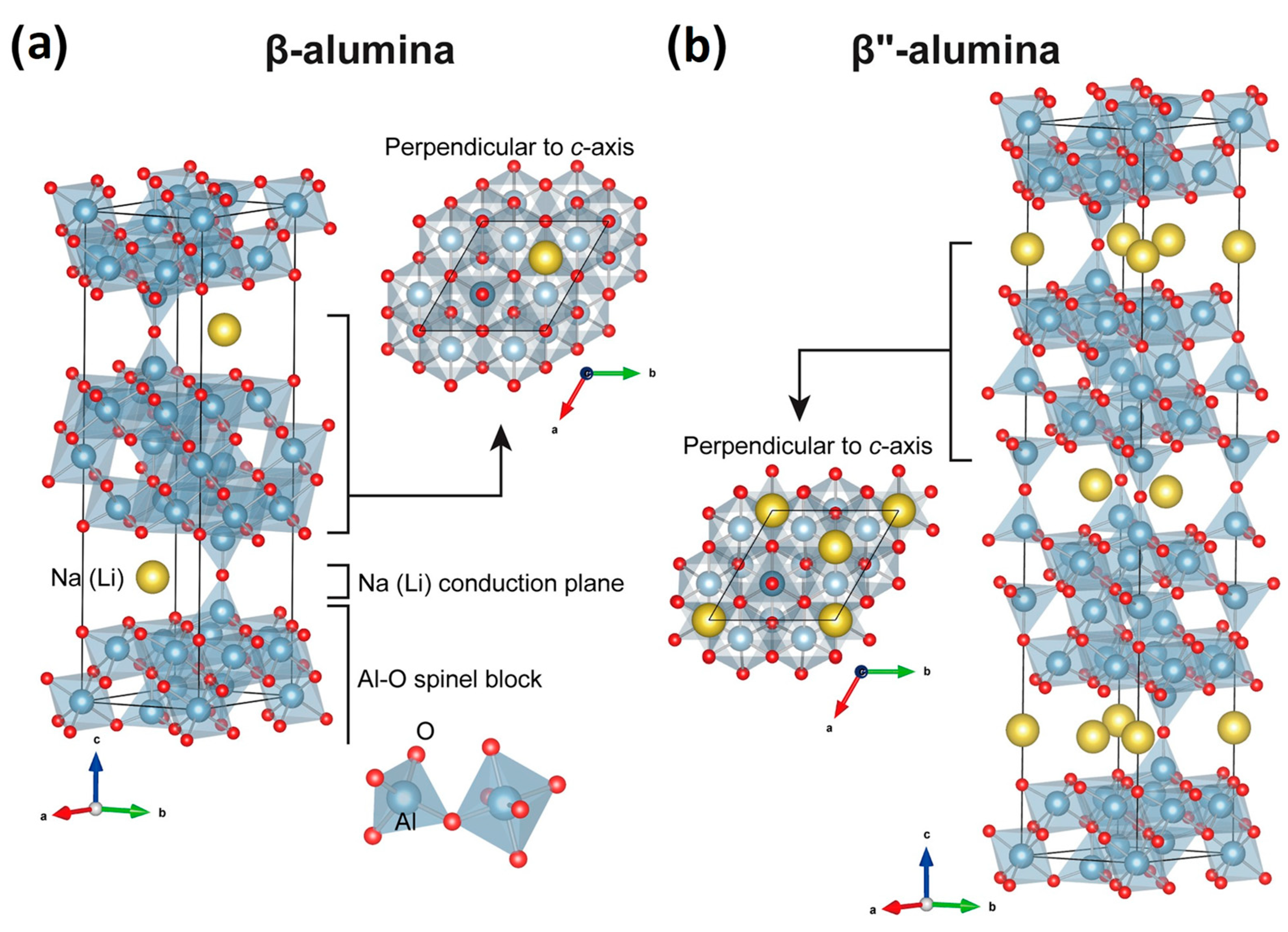
3.1. Beta-Alumina Solid Electrolyte

In 1967, Yao and Kummer [79] first reported the high ionic conductivity of beta-alumina solid electrolyte (BASE), a sodium polyaluminate with a general structure of Na2O·xAl2O3, which possesses alternating closely packed spinel blocks and loosely packed layers containing mobile sodium ions that are free to move under an electric field. As shown in Figure 5, two different crystal structures are formed as a function of x, sodium-beta-alumina for x = 8 − 11 (Na-β-Al2O3, hexagonal: P63/mmc; a0 = b0 = 5.59 Å, c0 = 22.61 Å) and sodium-beta″-alumina for x = 5 − 7 (Na-β″-Al2O3, rhombohedral: R3m; a0 = b0 = 5.60 Å, c0 = 33.95 Å) [35,80]. In both structures, sodium ions can move between lattice and interstitial sites in the conduction plane in a preferential direction [81]. However, the different oxygen stacking sequence across the conduction layer between the two structures implies a unit cell for β″-alumina 50% larger than that of β-alumina, giving more room for sodium ions and resulting in higher ionic conductivity [82,83]. For this reason, β″ is the preferred phase for the sodium-beta-alumina used in cell systems and for the fabrication of solid electrolytes.
Since the ionic transport mainly occurs along the conduction plane, single crystals of β″-alumina show higher conductivity compared to polycrystalline β″-alumina due to the absence of grain boundaries that tend to reduce the ionic movement, acting as a barrier to sodium transport. Although polycrystalline β″-alumina possesses sodium ion conductivity about 4–5 times lower than single crystals [84], it represents the primary material adopted in solid-state battery production. To improve its conductivity, efforts to optimize its fabrication have been made by producing β″-alumina ceramics with grains oriented along their C-axis, which show an improved ionic conductivity as a consequence of the alignment of the conduction plane [85]. The performance also depends on the boehmite precursor used for the powder synthesis [86,87].
However, the use of pure β″-alumina would not represent the most convenient choice for the design of a solid electrolyte ceramic. Synthesis methods typically involve powder-sintering processes that lead to pore formation, cracks and inhomogeneity of the ceramic body, which compromise its mechanical stability. The microstructure of the final electrolyte is also a relevant parameter that affects the balance between conductivity and fracture strength, where excessive grain growth results in higher ionic conductivity but more fragile ceramics [88,89,90]. In this context, the doping of β″-alumina with ZrO2 has been successfully applied to improve the mechanical properties, while other transition metal oxides such as TiO2, Mn3O4 and NiO have been proved to enhance both fracture strength and ionic conductivity [91,92].
The β″-alumina solid electrolyte also shows a high sensitivity to moisture, and its main negative effects were examined in a previous article [93]. As reported in the same work, the formation of a surface layer due to the ion exchange between Na and moisture was identified as the main aspect responsible for the decrease in ionic conductivity, although humidity can also induce microstructural changes in the bulk that lower the overall performance. In fact, it was reported that a small amount of NaAlO2, a phase formed during the electrolyte synthesis, could remain unreacted as a thin film along grain boundaries, causing humidity absorption from the atmosphere and generating cracks in the ceramic structure that lead to performance degradation. In this case, the use of Y2O3-stabilized zirconia (YSZ) as a dopant of β″-alumina permits the avoidance of the formation of NaAlO2 along the grain boundaries, thus strengthening the ceramic body and improving its moisture resistance [94].
Several methods have been developed to synthesize β″-alumina powders, among which are the conventionally used solid-state reactions and solution-based chemical methods. Usually, an alumina precursor is mixed with an appropriate amount of sodium salt and additives that act as phase stabilizers in a typical solid-state reaction. Before sintering at high temperatures, different ball milling and calcination steps are needed in order to obtain the final product. Despite the relative simplicity of solid-state synthesis, this technique suffers from the drawback formation of a two-phase mixture (β- and β″-alumina) and the presence of NaAlO2 impurities along grain boundaries that reduce the conductivity of the final electrolyte. In contrast with the solid-state reactions, sol–gel methods allow obtaining more homogeneous powders with higher surface areas [95,96]. Typically, these involve the use of a chelating agent to form a homogeneous solution of complex metals. Controlled evaporation at low temperatures induces the formation of a gel, which is subsequently dried to obtain the powder ready for calcination and sintering steps. Aside from the conventional sol–gel procedures, several other solution-based chemical methods are valid routes for preparing beta-alumina ceramics. For example, non-aqueous gel casting is a method where macromolecular gels generate colloidal ceramic components by the in situ polymerization of organic monomers [97]. This method has improved the electrolyte microstructure and the uniformity of ceramic green bodies.
Another example is the solution combustion technique, which combines the sol–gel method with the combustion process’s advantage that permits obtaining ultra-fine nano-sized powders [98,99]. Although solution-based processes have allowed researchers to overcome some disadvantages of the solid-state synthesis, they still require high temperatures for sintering: meaning sodium loss usually occurs above 1300 °C. Different synthesis techniques have been developed to minimize the amount of impurities and the formation of an undesired β-phase, together with the need for lowering sintering temperatures and promoting the use of abundant raw materials, hence reducing electrolyte production costs. Among these techniques, the most commonly employed include flame spray pyrolysis [100], the vapor phase process [101], microwave heating [102], laser chemical vapor deposition [80], electrophoretic deposition [103], the tape-casting method [104] and the double-zeta process [105].
The selection of the alumina source represents an essential factor in determining the phase purity (ratio between β- and β″-alumina), microstructure and conductivity of the electrolyte produced. For example, the use of a γ-Al2O3 precursor has allowed obtaining a 100 wt% of the β″-phase, whereas when employing α″-Al2O3, pseudo-boehmite or bayerite, a mixture of the two phases was achieved depending on the stabilizer [106]. Boehmite was also successfully adopted to achieve extremely dense and highly ionic-conductive β″-alumina [107]. Moreover, it was shown that the relative ratio between Na2O and Al2O3 has a remarkable influence on phase microstructure, defining volume density and bending strength [108]. Another critical factor to be considered is the choice of time and temperature for the calcination and sintering steps, which mainly affects sodium loss by evaporation and excessive grain growth, which directly influence ionic conductivity. Depending on the sintering temperature and sintering time, a difference of one order of magnitude in conductivity measured at 300 °C was reported on ceramics made from identical starting materials [109]. A further important consideration is the need to control the level of silicon and calcium oxides in boehmite below 200 ppm to prevent internal resistance rise due to the reduction in ionic conductivity of the ceramic electrolyte [110].
Various doping materials were used to minimize the number of impurities and stabilize the β″-phase. Specifically, the use of Li+ and/or Mg2+ salts is beneficial in maximizing the ratio of β″/β alumina [111,112] and stabilizing the β″-phase, which tends to decompose at temperatures higher than 1600 °C. Moreover, the use of MgO helped to enhance the relative density of the electrolyte and to promote the formation of a more homogeneous and compact microstructure [113]. A variety of other compounds were also used to improve the performance of β″-alumina ceramics from both a structural and ionic conductivity point of view. Y2O3-stabilized Zr2O (YSZ) is one of the most frequently used sintering agents; it enhances mechanical properties by limiting the grain growth [88,108,114] and is capable of modulating the phase transformation during the sintering process and increasing ionic conductivity [114,115]. Other additives were successfully employed for improving the electrolyte performance of β″-alumina electrolytes, such as Cr3, Ni2+, Fe3+, Mn4+ and Ta5+ [116,117,118,119,120]. Among these, titanium oxide (TiO2) was widely used for promoting the sintering process of β″-alumina [121]; lowering the sintering temperature [122]; and improving the densification rate [123], conductivity and fracture resistance [124].
Currently, the β″-alumina ceramic is the standard electrolyte commercially used in high-temperature sodium batteries [110], although advanced formulations were investigated with promising results when applied in prototypal sodium-metal chloride cells [88,92,125]. Despite this, one of the main limitations of β″-alumina is the poor ionic conductivity at low temperatures, which contributes to the total resistance of the cell and limits the operation of the batteries, particularly below 200 °C [35]. Since the resistance of β″-alumina to sodium ion transfer is directly proportional to the material thickness, the manufacturing of thinner ceramic electrolytes might be one of the solutions to circumvent this technical challenge. For instance, Li et al. [46] used a β″-alumina disc with 500 μm thickness, allowing the operation of a planar Na-NiCl2 cell at an intermediate temperature of 190 °C. However, although YSZ was employed in order to reinforce the BASE disc, the relatively low thickness could drastically decrease the robustness of the cell by lowering the mechanical strength.
In practice, a more feasible solution is often used to reduce the internal resistance of the cell [33,35,126,127,128]. This consists of surface modification of the β″-alumina electrolyte to improve the wettability with molten sodium at an intermediate or low operating temperature. In fact, an intimate interface contact between the sodium negative electrode and the β″-alumina surface results in low polarization and improved electrochemical cell performance. Sudworth and Tilley proposed for the first time the modification of a sodium-beta-alumina surface with Pb/PbO in a Na-S battery [129]. In addition, other modifications methods, e.g., either coatings with Ni nanowires or Na alloy (Na-Bi, Na-Sn and Na-In) coatings and a screen-printed Pt grid, have shown to greatly improve the wettability of the β″-alumina ceramics by molten sodium [34,130,131].
Recently, a different approach to decreasing the area-specific resistance (ASR) of the β″-alumina ceramic discs while maintaining good mechanical strength was proposed by Jung et al. [90]. They presented a high-energy-efficiency Na-NiCl2 battery operating at 190 °C using a bi-layer ceramic disc consisting of a thin, dense layer coupled with a thick porous BASE support that adds strength to the ceramic disc without increasing the resistivity [88].
According to the schematic view in Figure 6, the majority of Na+ ion transportation happens through the dense layer with a short path length (path #1), instead of path #2 with a longer length but less resistance. In conclusion, they demonstrate that, in addition to using a ceramic electrolyte with excellent mechanical resistance, the improved resistivity to ion transfer allowed obtaining a Na-NiCl2 cell with better energy efficiency than a similar cell using a standard dense ceramic electrolyte.

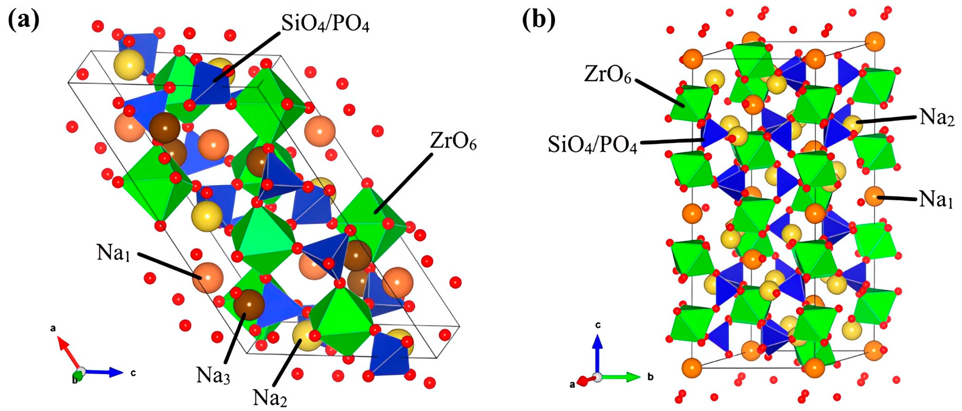
3.2. NaSICON Solid Electrolyte

NaSICON (Na+ SuperIonic CONductor) solid-state electrolytes are among the most widely studied electrolytes for sodium batteries. They have high ionic conductivity, good electrochemical stability and excellent mechanical properties, which focused the scientific community’s interest in these types of materials. The NaSICON structure was firstly reported in 1976 by Goodenough and Hong [132], who proposed the formula Na1+xZr2SixP3−xO12 (0 ≤ x ≤ 3) as a material derived from NaZr2P3O12 with partial substitution of P with Si. Since then, several NaSICON-based materials have been studied and developed, demonstrating the possibility of exploring a wide range of atomic compositions starting from the typical Na2O-P2O5-SiO2-ZrO2 quaternary formulation [133].
The most widely known composition, Na3Zr2Si2PO12, exhibits the highest ionic conductivity of 2.0 × 10⁻¹ S cm−1 at 300 °C (similar to that of Na-β″-Al2O3) and of 6.7 × 10⁻⁴ S cm−1 at room temperature [134]. Two different phases can be identified as a function of the stoichiometric composition: rhombohedral (R-3c, with 0 ≤ x ≤ 3), where tetrahedral SiO4 and PO4 share their corners with octahedral ZrO6, and monoclinic (C2/c, with 1.8 ≤ x ≤ 2.2), the stable phase at a low temperature [135]. These structures possess several cavities through which sodium ions can easily migrate, promoting and enhancing ionic conductivity.
Figure 7 shows the different kinds of sites where sodium ions can sit in bottleneck regions. In the rhombohedral structure, four sites per formula unit of NaSICON can be identified: one Na1 and three Na2 positions, with six O atoms from tetrahedral SiO4 and PO4 coordinating the Na+ ions. The monoclinic phase displays an additional Na3 site, with threefold coordination with O atoms from octahedral ZrO6. The monoclinic–rhombohedral transition occurring with temperature induces a structural rearrangement that changes the type and number of sites where sodium ions can migrate through [136], thus affecting the diffusion pathway and increasing the ionic conductivity of the material and lowering the activation energy [137].
In NaSICON-type materials, ionic conduction occurs through the bottleneck regions within the structure. Their size can play a crucial role in lowering the migration energy barrier, thus improving Na-ion transport. For this reason, the doping of the electrolyte carried out by the partial aliovalent substitution of zirconium with atoms of appropriate dimension has helped to enlarge the bottleneck size and lower the monoclinic–rhombohedral transition temperature, stabilizing the rhombohedral phase with higher symmetry [138].
In this context, the substitution of 2.5% of zirconium with Mg2+ was found to be more beneficial than the other alkaline ions (Ca2+, Sr2+ and Ba2+), given the smaller ionic radius that causes an expansion of bottleneck cavities, increasing the ionic conductivity [139]. High Na-ion transport was also achieved by using Sc3+ as a dopant thanks to its similar size to Zr4+ [140]. The 20% substitution was the optimal amount to produce the material with the highest ionic conductivity at room temperature [141]. Another study investigated the influence of the valence state and the loading of a series of dopants (Nb5+, Ti4+, Y3+ and Zn2+) on the conduction properties of NaSICON electrolytes. The best results were obtained with a 10% Zn substitution, which promoted high densification and a lower sintering temperature [142]. Cerium-doped NaSICON showed improved lattice parameters, which facilitate Na-ion transport and reduce the activation energy, but relevant changes occurring in the grain size and morphology caused a decrease in bulk conductivity [143]. Interesting works reported an equimolar substitution of Zr4+ with Al3+ and Y3+, giving a detailed analysis of structure modification as a function of the doping load. This study demonstrated that although the two doping atoms fulfil the steric requirements to obtain proper bottleneck size, the electrostatic interactions occurring can negatively affect the ionic conductivity despite the higher number of Na-ions per formula unit [144].
Moreover, the investigation of their mechanical properties by depth-sensitive indentation showed relevant correlations between structure composition and material strength [145]. A different strategy has also been reported to improve Na-ion transport, which involves adding NaF to the precursor mixture without any atomic substitution. The results showed that NaF can promote the conversion of the monoclinic to the rhombohedral phase, creating a “binder-like glassy phase” at the grain boundaries that improves the total densification and thus the ionic conductivity [146].
As a function of the strategy adopted for the synthesis of NaSICON electrolytes, secondary undesired phases (usually ZrO2 and Na3PO4) can be present as impurities due to high-temperature processes, which generally cause sodium oxide evaporation. Standard methods employed to synthesize NaSICON materials are solid-state processes, which generally involve the ball milling of precursors following calcination and sintering steps to obtain the ultimate product. All these stages, together with the type and amounts of precursors to be adopted, deeply influence the final properties of the ceramic, such as the degree of crystallinity, purity, mechanical strength and ionic conductivity. Therefore, several parameters must be considered to produce a material with the desired characteristics. The choice of the starting materials is one of the key parameters that can influence electrolyte properties. Nanoscale precursors were found to enhance ionic conductivity compared with more extensive microscopic starting materials treated under the same sintering conditions due to an increased surface area of the particles resulting in more homogenous grain growth and higher densification, which finally lowers the electrolyte resistance [147]. Similarly, higher densification during sintering, hence higher ionic conductivity, has been achieved by reducing particle size with an additional ball milling process performed after the calcination step [148]. A similar effect can also be obtained with the mechanical activation of raw precursors by prolonged milling time, which resulted in microstructured nanometric materials producing dense single-phase highly conductive ceramics with a submicrometric grain size [149].
Several works have demonstrated the improvement of Na-ion conductivity by varying the amounts of precursors adopted for the synthesis, moving away from the typical NaSICON stoichiometry by adding an excess of sodium. This procedure was found to reduce the electrolyte resistance due to the improved mechanisms of Na-ion transport at the grain boundary and grain diffusion. This phenomenon can be caused by an increase in bottleneck size in the sodium conduction channels [150] or by a modification of the ratio between occupied and vacant Na ion sites [151]. Furthermore, using an excess of sodium precursor can compensate for the sodium loss during the sintering step [152], which represents another critical stage that defines the final properties of the ceramic. Sintering temperature and time were widely investigated to gain knowledge of the effect of these parameters. The results found in the literature showed that high temperatures generally lead to better densification, with long sintering time promoting grain growth, thus reducing grain boundary resistance and enhancing ionic conductivity [153]. On another hand, secondary phases normally appearing with high-temperature sintering can increase the porosity, thereby lowering the relative density [154].
Several synthetic techniques have been adopted to reduce sintering temperatures and times to minimize both undesirable reactions and fabrication costs. For example, spark plasma and field-assisted sintering methods use small electrical currents and short sintering times to produce highly dense ceramics yet maintain optimal control of phases and material composition [155]. On another side, cold hydrostatic sintering technology reduces the temperature of conventional sintering by a pre-densification step at low temperatures and high pressure [156]. In addition, the microwave sintering method was adopted to successfully obtain high densification using short sintering times and relatively low temperatures [157]. Contrarily to solid-state methods, liquid-based approaches such as sol–gel [158], solution-assisted solid-state reactions [159] and co-precipitation methods [160] allow obtaining ceramic materials with better control over particle size and morphology, together with the use of sintering temperatures that are generally much lower. These techniques permit the mixing of precursors at the molecular level, giving highly pure and homogeneous nanomaterials, but with the overall drawback of limited scalability and long times for synthesis.
Despite plenty of works focusing on the synthesis, characterization and optimization of the chemical–physical properties of NaSICON, there is a lack of research papers showing its effectiveness in high-temperature molten sodium batteries. Only Kim et al. [37] proposed a prototypal tubular Na-NiCl2 cell with a 9.6 Ah capacity, where a NaSICON tube made of a dense ceramic (Figure 8a,b) was used as the electrolyte. The comparison of the charge–discharge profiles recorded at 195 °C for a NaSICON-based cell and for a similar cell, in which a common β″-alumina electrolyte was used (Figure 8c,d), revealed the clear advantage of NaSICON at this low operating temperature, which was attributed to its higher Na+ ionic conductivity. Due to the promising results, in a following work, they again used the same NaSICON-based cell to investigate the optimum manufacturing condition for the granule-type cathodes [38].
Contrary to the limited number of publications, many patents have suggested molten sodium batteries operating at intermediate temperatures, which employ a NaSICON ceramic membrane as a solid electrolyte [41]. Ceramatec Inc.(Salt Lake City, UT, USA) [161] patented a Na-S battery operating at a temperature below 200 °C in which a non-porous NaSICON membrane was used. They claimed that, although a relevant capacity fade of the Na-S cell occurred during the first ten cycles, the non-porous solid electrolyte stops the migration of sodium polysulfides to the anode in the following cycles, avoiding further irreversible capacity loss. SK Innovation [162] also patented a Na-S battery operating from 120 °C to 150 °C, in which a sulfur cathode was mixed with a sodium salt dissolved in an organic solvent such as N-methylformamide (NMF). To enable low-temperature operation, high ion-conductive Y or Fe-doped NaSICON was used as a solid electrolyte separator.
Metal halide sodium batteries employing NaSICON solid electrolytes were also patented. However, to enable low-temperature operation, low-melting-temperature secondary electrolytes were employed in combination with NaSICON. These secondary electrolytes generally consist of a molten eutectic mixture of sodium haloaluminate salts, NaAlX′4–δX″δ, where 0 < δ < 4, and X′ is Cl and X″ is Br, I [163] or MxNa1−yAlCl4−yHy, where M is a metal cation and H is an anion of the substituting salt [164]. It is reported that, by partially replacing the NaCl in the standard NaAlCl4 catholyte with the above alkali metal salts, the polarization effect inside the cathode can be reduced, allowing better performance than a standard Na-NiCl2 ZEBRA cell, beyond the use of a NaSICON ceramic electrolyte. Additives that can be added to the NaAlX4 electrolyte to be used in a ZEBRA battery with NaSICON membranes have been also patented [165]. These additives have a moiety with a partial positive charge (δ+) that weakens the ionic bond between the Na+ ions and the secondary electrolyte. Additives such as SOCl2, SO2, dimethyl sulfoxide (DMSO, CH3SOCH3), CH3S(O)Cl and SO2Cl2 can improve the sodium conductivity by at least 10%, also lowering the viscosity of the electrolyte solution.
Beyond their use in molten sodium batteries, NaSICON ceramic electrolytes represent the most suitable choice for the development of new-generation low-temperature metal halide batteries based on sodium iodide cathodes. In this regard, Small et al. [166] reported a new metal halide battery based on a molten sodium anode, a sodium iodide/aluminum chloride (NaI/AlCl3) cathode and a highly conductive NaSICON ceramic separator operating at an intermediate temperature of 120–180 °C. The cell showed a lifetime average coulombic efficiency as high as 99.45% and an energy efficiency of 81.96% over 3000 h under dynamic testing (Figure 9). Moreover, the same research group investigated advanced cathode compositions such as sodium iodide/aluminum bromide (NaI/AlBr3) [167] and sodium iodide-gallium chloride (NaI/GaCl3) [168], presenting new fully molten, inorganic sodium batteries capable of operating at the low temperature of 110 °C.

4. Cell Design

4.1. History and Evolution

The first concept of a sodium-metal chloride cell dates to the mid-1970s, thanks to the ZEBRA project headed by Johan Coetzer in Pretoria, South Africa. However, the most important features of the cell design derive from the earlier sodium-sulfur and lithium-iron sulfide batteries, which were the first high-temperature energy storage technologies proposed [169]. Already during the early 1960s, there was a large interest in the use of metallic sodium because of its high standard reduction potential (−2.71 V). In the same years, the discovery of the excellent high-temperature ionic conductivity of the β″-alumina ceramic opened the way for the development of batteries using liquid sodium as the anode. In 1966, Ford Motor Company demonstrated the effective use of a sodium-sulfur battery system for EV applications [170], in which a tubular cell design was adopted in the final formulation of the ZEBRA cell. In fact, the ceramic electrolyte used in the first-generation ZEBRA cell was supplied by the British Rail Technical Center (BRTC), which already produced β″-alumina tubes for sulfur cells. At the end of the ZEBRA project, the cell concept was a sodium-sulfur cell in which the highly corrosive sulfur cathode was replaced by transition metal chlorides dispersed in binary sodium tetrachloroaluminate molten salt (AlCl3 + NaCl → NaAlCl4). Further developments of the ZEBRA cell were made after the end of the ZEBRA project during a collaboration between Beta R&D Ltd. (formed by members of the BRTC team) and the Anglo-American Corporation (AAC). The result of this collaboration led to the presentation of the first tubular ZEBRA cell made with a central cathode based on FeCl2/Fe or NiCl2/Ni. The first version of the ZEBRA cell, of which more comprehensive details were published by Bones et al. in 1987, was based on FeCl2/Fe [56]. The cell design used for this prototype was a British Rail BR16 cell series, in which the cathode, made by iron discs or solid cylinders with optimized structure and porosity, was obtained by the sintering of iron powder precursors. These were in turn bolted onto a mild steel rod, which acts as a current collector (Figure 10). Before the cell assembly, the iron cathode was converted into FeCl2 by gaseous chlorination. It was demonstrated that optimized Na-β″-alumina-Fe/FeCl2 cells were able to provide a practical specific energy higher than 130 Wh kg−1 at a 5 h discharge rate.
Although the use of iron has the advantage of low cost, parallel experiments had shown that the addition of nickel in the iron-based cathode provided greater stability and higher specific energy. A short time later, Bones et al. [49] proposed a new cell design based on a NiCl2/Ni cathode. One of the main novelties of this new configuration was that, unlike the previous version based on iron, this cell could be assembled in the discharged state by filling the cathode side with a mixture of Ni metal and NaCl powders. This cell design, despite its simpler assembly, showed longer cycle life (>2000 cycles), a higher open-circuit voltage of 2.58 V at 300 °C and high energy and power density in comparison to the Fe-based design.
To demonstrate the feasibility of this technology to power electric cars, the cell design was brought to the next level of development. Much of this work was accomplished thanks to the joint venture between AAC and AEG-Daimler-Benz Industries, which began in 1989. The result of this collaboration was the development of a totally sealed slim line cell (SL/09) with 30 Ah capacity, which was made of a cylindrical β″-alumina tube with a central NiCl2/Ni positive electrode. However, as vehicle trials of batteries assembled with the aforementioned cells did not meet the power requirements needed for passenger vehicles, a research program was carried out to further optimize the cell design to improve the power of the ZEBRA cell. The main changes regarded the cross-section of the β″-alumina tube, moving from cylindrical to cruciform, and the addition of iron in combination with nickel at the cathode side, together with other additives such as aluminum and sodium fluoride. The new design led to cells of 32 Ah capacity with a high specific pulse power of 250 W kg−1 and an improved energy density of 120 Wh kg−1 [171]. Moreover, this cell was employed for the realization of the first battery system able to meet the criteria defined by the United States Advanced Battery Consortium (USABC). These requirements included power and energy density, cycle and calendar life, and operating temperatures for different climate conditions, in addition to passing all abuse tests such as freeze–thaw cycling, overheating, over-charging and short circuits [172].
Further design improvements, which led to the current commercial cell configuration, were made only after the Swiss company MES-DEA purchased the ZEBRA technology. During this period, a research program was supported to increase the energy density of the single cell up to about 130 Wh kg−1. However, most of these improvements were related only to the optimization of the composition and granulation of the active material constituting the positive electrode [173]. Since 2010, the ZEBRA cell technology has been owned by FIAMM -Sonick, a company born from the acquisition of MES-DEA by the Italian group FIAMM [15]. However, the interest of the American company General Electric in this technology should also be mentioned. In fact, for a few years around 2013, they developed and used a similar cell design to assemble a sodium-nickel chloride battery marketed under the DurathonTM brand [174]. In 2017, along with the cooperation between Chilwee Group and General Electric Company, DurathonTM battery production came to China. The collaboration of the two sides combined industrial and technological advantages to expand the application of Durathon batteries on a larger scale.
All the developments and optimizations of cell design carried out over the years have been almost exclusively directed to the tubular configuration. Indeed, the tube-shaped β″-alumina ceramic ensures excellent mechanical stability, reducing the critical issues related to the seal between the different parts of the cell. It is worth mentioning that Sudworth, a pioneer of the ZEBRA cell, had first proposed a planar cell configuration for the sodium-sulfur technology [130]. The outputs from this attempt remarked that a planar cell would be superior in terms of easiness of stacking, heat management, ability to deliver high specific energy and power and potentially lower manufacturing costs. However, its use results in a large sealing area between the different parts and mechanical instability of the β″-alumina disk as the cell size increases.
As discussed in detail in Section 4.4, extensive research has been carried out at PNNL by the Lemmon and Sprenkle team [175] aiming to develop and overcome the previous limitations of the planar configuration, and also aiming to improve its performance even in comparison with tubular geometry.

4.2. Tubular Cell

The most popular tubular design used for ZEBRA batteries displays a cell configuration where the cathode material is positioned inside the β″-alumina tube, while the metal sodium is placed in the outer part. The β″-alumina tube is housed in a metallic case isolated and sealed with a ceramic ring. As shown in Figure 11, the main differences between the first and current generation of the tubular cell, in addition to the geometry of the β″-alumina tube, are the simplified sealing method, which eliminates double α-alumina rings, and the new wicking arrangement for metal sodium supply. In the first generation of the tubular cell, the sodium distribution on the surface of the β″-alumina was ensured by packing carbon beads between a close-fitting metal tube and the ceramic electrolyte. In the current generation, a wick system based only on metal shims eliminates the annulus of carbon beads, although a thin layer of carbon on the β″-alumina tube is still present to improve the wettability of the ceramic by molten sodium [176,177].
The state of the art of tubular design is represented by the FIAMM Monolith cell (ML3X). It has a nominal voltage of 2.58 V with a rated capacity of 38–40 Ah (at discharge rates of C/2 or C/5, respectively), a specific energy of 140 Wh kg−1 (cell weight 690 g), an energy density of 317 Wh l−1 and an optimal operating temperature in the range of 270–350 °C [15,17,178]. An exploded view and all the main components are shown in Figure 12.
The cell is enclosed in a prismatic-shaped metal container (36 mm × 36 mm × 235 mm) made from a continuous welded steel tape coated with nickel and a lased welded bottom cap. Since the metal case is in contact with the molten sodium, its external surface also acts as the negative pole of the cell. One of the most important components of the cell is the cloverleaf-shaped β″-alumina tube, which separates the cell into a cathode and an anode compartment. The cathodic side, consisting of a current collector immersed in the porous active cathode mixture, is located inside the ceramic tube. The anodic side, which contains the molten sodium, is located between the ceramic and the cell case. In addition, properly shaped metal foils that are close in contact with the β″-alumina tube are also placed in the same compartment. The sealing of the external terminals of the cell, which ensures the electrical separation between positive and negative electrodes, is obtained with an α-alumina collar equipped with two nickel rings tied to the ceramic by thermocompression bonding (TCB). The α-alumina collar is then bonded on top of the β″-alumina tube by a borosilicate sealing glass [15], while the nickel rings are laser welded to the pin of the positive current collectors and the external steel case of the cell. To ensure an inert atmosphere inside the cell, a helium filling is carried out before the final sealing [178].
The sum of the weights of all components affects the effective specific energy of the cell. The weight distribution of the single elements in a typical monolith ZEBRA cell is shown in Figure 13. The theoretical specific energy, which takes into account only the active mass of the reactants (nickel only), is about 790 Wh kg−1 [179]. However, for the most recent tubular cell configuration, the actual specific energy is around 120–140 Wh kg−1. This is because nickel represents just about a third of the total cell weight, while the β″-alumina tube, secondary electrolyte and steel case have a relevant contribution [176].

4.2.1. Cathode Side

The cathode side of the cell mainly includes the active material, the secondary electrolyte, additives, the current collector and other functional parts. A deep focus on both standard and alternative active cathode materials is covered in Section 2. Nevertheless, a brief description with essential information about standard materials used in the commercial tubular cell and their effective role in cell operation is given below.
Since the cell is assembled in the discharged state, sodium chloride, nickel and iron powders are placed as starting active materials at the positive electrode. These are also blended with small quantities of additives. Typically, an excess of nickel is used to ensure an adequate electrical path, which promotes the conductivity across the positive electrode in the fully charged state, i.e., when the active material is converted to NiCl2. In order to prevent the segregation of single components, the powders are finely ground, mixed, compacted in granules, and then filled into the β″-alumina tube. After a drying step under vacuum at 285 °C to remove any trace of moisture, the molten NaAlCl4 secondary electrolyte is injected into the tube and then vacuum-impregnated into the granulated active material [176]. Although NaAlCl4 also contributes to the electrochemical reactions of the cell through complex paths involving active species, its main role is to enhance the sodium ions’ mobility throughout the cathode compartment in the molten state at the standard operating temperature. It is also essential to prevent critical cell failures in the event of the β″-alumina tube cracking. Indeed, by reacting with the aluminum, it can seal small cracks, limiting the energy released in the event of an intern short circuit. It also acts as a sodium reserve in the case of overloading of the cell, limiting damages [10,179]. Considering that for effective operation the NaAlCl4 must be in the liquid state, its melting point (158 °C) corresponds to the theoretical minimum operating temperature of the cell.
Iron sulfide (FeS), sodium fluoride (NaF), sodium iodide (NaI) and aluminum powder are the typical additives used in commercial cells, although manganese has also been reported in a recent patent [180]. FeS is used to prevent rapid capacity loss during cycling, limiting the growth of nickel particles [176]. NaF is added to improve the over-charge tolerance and to prevent internal resistance increase by limiting the solubility of iron in the molten salt. In fact, due to the high solubility of FeCl2 in the secondary electrolyte, the iron ions could diffuse into the crystal structure of the β″-alumina electrolyte causing a resistance rise. A NaI additive contributes to increasing the usable capacity and reducing the impedance of the cell [30]. Aluminum powder has multiple functions. First, it provides an additional amount of sodium metal thanks to its ability to react with NaCl, compensating the sodium potentially trapped in the anode compartment, which is no longer available at the end of discharge. As a secondary effect, it leads to a homogeneous porosity throughout the active material, which promotes high c-rate performance and ensures full charge acceptance on the initial charge [171,176].
The positive current collector of the cell, which consists of a continuous loop of wire with a hairpin shape, is buried in the granulated active powders. It is typically made of nickel, but for high-power applications, a nickel-coated copper core wire is also used. Copper has a specific resistivity about seven times lower than nickel; therefore, its use contributes to reducing the internal resistance of the cell, which results in power improvement [181]. Unfortunately, copper is electroactive in the cell environment, so it must be coated with a nickel layer to be used. Nevertheless, the simple and cheap manufacturing process and the lower cost compared to pure nickel make this combination cost effective.
A strip of carbon felt is also placed in the cathode side of the cell to ensure an adequate contact between the current collector and the wall of the β″-alumina tube. This element, which does not add noticeable weight to the cell thanks to its high porosity (>95% void), has the main role of uniformly distributing the molten secondary electrolyte through the positive electrode [181].

4.2.2. Anode Side

The anode side of a ZEBRA cell mainly consists of metal sodium, which is in the liquid state (melting point 97.8 °C) under standard operating temperatures. It is located in the space between the β″-alumina tube and the cell case. A critical aspect of this configuration is the way to maintain the liquid sodium in good contact with the wall of the β″-alumina tube, minimizing the interfacial polarization effects. To solve this issue, different technical approaches have been suggested [182]. A top reservoir of metal is a simple strategy to keep the level of sodium in the anode compartment high enough to constantly wet the whole β″-alumina surface. However, this method imposes the use of an excess of sodium, with resulting drawbacks such as additional weight and handling of metal sodium during the cell assembly. Another way to promote the contact between molten sodium and the β″-alumina tube is the use of a pressurized system with inert gas. In this case, the applied pressure on the sodium reserve placed at the bottom of the cell leads to a rise in the gap between the walls of the ceramic electrolyte and the external case. Although this design can offer a more efficient solution than the previous one, it is still necessary to use an excess of sodium and specific assembly methods, making this solution more suitable only for large vertical cells. Despite this, in the more conventional tubular cell configuration, the sodium reservoir is replaced by a much more functional system based on capillary sodium wick shims. This consists of four 0.1 mm thick mild steel foils (Figure 12), which tightly dress the β″-alumina tube and establish the electrical contact with the cell case. In this design, capillary forces act on liquid sodium, which easily spreads through the thin gaps between the metal shims and the β″-alumina tube covering the whole surface of the electrolyte during the normal operation of the cell. Since it is not possible to maintain a regular capillary gap over the whole surface of the tube, a thin layer of porous carbon is also applied in order to ensure uniform coverage of the β″-alumina surface. This design has the main advantage employing just the amount of sodium required by the cell reactions without the need of a reservoir, thus optimizing the specific energy, minimizing the cell dimensions, reducing the cost and eliminating the handling of metal sodium. However, it should be noted that a little excess of metal sodium must be considered in any case in order to compensate for the amount of metal inevitably trapped in the anode compartment during cell operation, which would lead to a limited discharge capacity. In practice, the aluminum additive used in the cathode generates the excess of sodium needed, avoiding the introduction of metallic sodium in the cell assembly process [181]. Therefore, the cells can be assembled in the discharged state, and sodium is produced only during the first charge with the aid of the metal shims that ensure the electrical conductivity until the first drop of sodium is generated, which then rapidly spreads on the surface of the ceramic tube. This simplifies the ZEBRA cell manufacturing while making it safe, due to the unnecessary handling of high-reactive metallic sodium in the presence of moisture and oxygen.

4.2.3. Solid Electrolyte Ceramic Tube
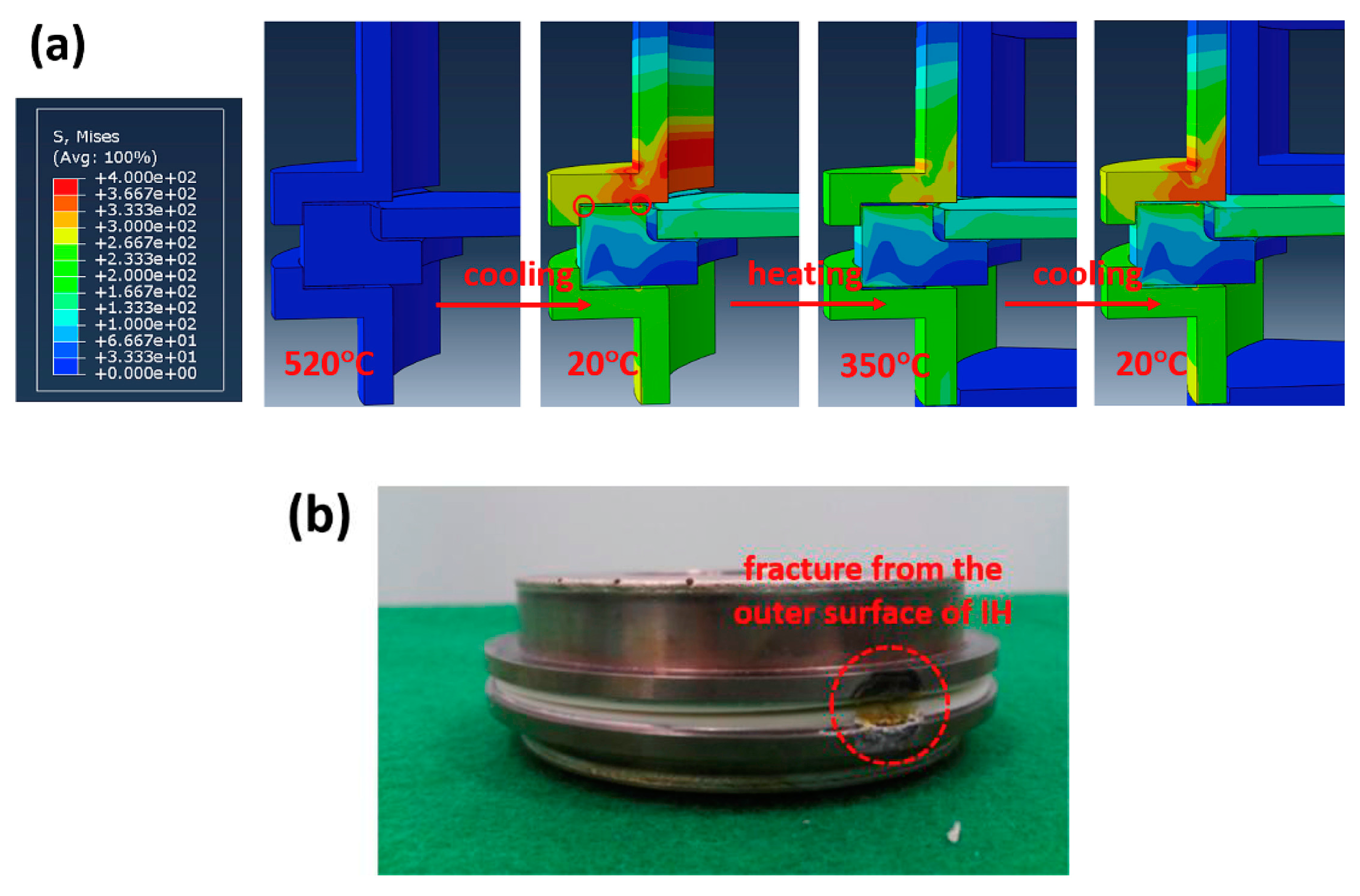
The solid electrolyte is a crucial element since the entire design of the cell depends on its geometry. It has the dual role of acting as a separator between the molten sodium anode and metal halide cathode and favors the Na-ion transport between the two active species at the electrodes. The main requirements of the solid electrolyte are high ionic conductivity towards Na+ species, high electrical resistance, excellent chemical stability, good mechanical properties and thermal stability at typical operating temperatures above 270 °C.
Current commercial ZEBRA cells use solid electrolyte tubes exclusively made of β″-alumina ceramic obtained from the boehmite precursor. A thorough discussion regarding the preparation method, structure and performance of the material is reported in Section 3.1.
As already mentioned, the first generation of ZEBRA cells utilized a cylindrical β″-alumina tube borrowed from the sodium-sulfur technology. However, the main drawback of the cell design was the limited pulse power with decreasing depth of discharge. This effect was due to the increase in the ohmic resistance in the porous positive electrode with consequent power loss. As mathematically modelled in a previous paper [183], the reaction front in the cathode during cell operation moves away from the electrolyte interface, causing a gradual increase in the internal resistance of the cell. During discharge, the material transformation starts at the surface of the ceramic electrolyte, leading to a progressively thicker interface made of converted material. Consequently, due to the longer distance to be overbridged between the reaction front and ceramic, the ionic resistance of the secondary electrolyte becomes larger. The solution to this drawback was to increase the contact surface between the solid electrolyte and the positive active mass and reduce the thickness of the positive electrode by using a long-perimeter cross-section for the ceramic tube. Different tube profiles, such as circular, oval, ellipsoidal, polygonal, cruciform or star-shaped, have been proposed and patented [184]. However, due to the difficulty in the manufacturing process and the lack of mechanical stability for particular shapes, only the standard cylindrical tube and the four-lobe (or clover-leaf) optimized tube with smoothed corners have been effectively employed (Figure 14). In particular, the shape of the clover-leaf tube leads to an increase in the active surface of about 40% compared to a standard cylindrical geometry, while maintaining the same overall dimensions of the cell. This contributes to reducing its internal resistance by almost one-third, with beneficial effects at any depth of discharge [181].
The process used for the fabrication of β″-alumina tubes is crucial in achieving the characteristics of ionic conductivity, density and mechanical strength required by the application. A variety of different production routes have been proposed for the manufacturing process of the closed-end tube-form green β″-alumina powder, including isostatic pressing, extrusion, slip casting and electrophoretic deposition. However, other routes that differ in the sintering method, such as zone sintering, hot pressing and plasma sintering, can be used to improve the final characteristics of the ceramic electrolyte [82].
For large-volume production, simple and low-cost processes would be preferable. The extrusion method followed by sintering of high-density β″-alumina tubes offers this potential. Indeed, it was one of the first methods patented by the Ford Motor Company [185]. However, this method has not found wide commercial use due to special requirements for the adaption to solid electrolyte production, including the selection of binders for suitable extrudable slurries and the complex design of the dies for the closed-end tube geometry. Nevertheless, this process has regained new interest in recent years. For instance, Avinash et al. [186] prepared pure and Li-doped sodium β″-alumina tubes, exhibiting high density and Na-ion conductivity consistent with the typical values for the material. Hu et al. [187] also used an extrusion process for the fabrication of a straight thin-walled ZrO2/β″-alumina tube with properties similar to commercial tubes produced with the electrophoretic deposition process. ZrO2 was used with beneficial effects for the achievement of the near-theoretical density of the ceramic, elimination of calcium impurities and prevention of uncontrolled secondary grain growth during sintering, thereby resulting in improved mechanical strength.
The process used for the fabrication of β″-alumina tubes in current commercial ZEBRA cells is exclusively based on isostatic pressing. The β″-alumina powder, produced by the calcination of boehmite according to the route discussed above, is first dispersed in water and finely milled to have a particle size between 1 and 2 μm; then, organic binders are added to the slurry [176,181]. The correct control of the grain size is crucial to confer good flow properties for the fast mold filling, while the organic binders are essential for the high strength of the green body to be handled during the next steps of the process [110]. To obtain a powder with suitable characteristics for isostatic pressing, the slurry is atomized by a spray-drying technique. The powder is then pressed for about 20 s under rigorous environmental conditions into the desired monolith tubular shape, sintered in a gas-fired tunnel at 1595 °C for about 24 h, then cooled down at 300 °C. Finally, the tubes are conveyed to the cutting station, where they are cut to a proper length and rectified on the open profile of the monolith [178,181]. To obtain the required mechanical characteristics, all the production phases must be carefully controlled. The presence of pores on the surface can cause crack formation as a consequence of the pressure generated by dendrite formation at the anode side. The β″-alumina composition is also an important factor in determining the resistance of the material to the dendrite formation. The typical β″-alumina tube composition used in ZEBRA cells with about 9.2% Na2O, 0.8% Li2O and 90% β″-Al2O3 has been proven to be resistant to dendrite formation up to current densities of 0.5 A cm−2, which is higher than the maximum current density used during the charge [110].

4.2.4. Cell Sealing

Hermetic sealing of the cell is crucial for both safety and performance reasons. The most important requirement of the seal is that all internal and external joints must be gas-tight. In fact, due to the high operation temperature of the battery, it is necessary to prevent the leakage of the high-pressure alkali vapors generated by the liquid phases. Moreover, the prevention of humidity or oxygen passage from the environment to the internal cell must be guaranteed due to the high reactivity of the active materials. Since both the positive and negative electrodes generate an aggressive environment, together with the fact that the cell can undergo thermal expansion as the effect of temperature variation, this seal must have good chemical stability and adequate thermo-mechanical properties.
A schematic section of the top part of a conventional tubular ZEBRA cell is shown in Figure 15. The sealing of the cell from the external environment is guaranteed by effective laser-welded metal joints. On the contrary, the link between heterogeneous components, such as the joints between metallic and ceramic elements, represents the most critical aspect of sealing. To meet the related needs, an α-alumina collar, glass-sealed to the β″-alumina tube and equipped with two thermocompression-bonded (TCB) nickel rings, makes up the top seal of the cell. The α-alumina collar isolates the battery compartments from each other both ionically and electronically, while the two nickel rings serve as metal joint elements to be welded with the external case and positive current collector [188].
TCB is a metal welding technique in which the bond is realized by solid-state diffusion without forming molten phases. The method consists of heating and applying mechanical pressure on two joining bodies. Their synergic effect facilitates the diffusion of the metal, thus resulting in a metallurgical bond between the two surfaces. This technique is used in tubular molten sodium cells to join nickel rings with an α-alumina collar, realizing a heterogeneous metal–ceramic link. Although an excellent joint could be obtained by directly bonding the metal rings to the ceramic surface, cracking can occur due to the different thermal expansion of the two parts during the operation. In addition, as an effect of the reactive NaAlCl4 vapors, the junction region is susceptible to stress corrosion. To overcome these issues, a method to apply an interlayer between the two parts is typically used [189]. This consists of a first step in which the surface of the ceramic collar is metallized with a molybdenum layer under a reducing atmosphere; then, the nickel rings are thermocompression-bonded to the metallized layer. Metallizing the surface of the ceramic component is necessary to have a continuous glass phase dispersed therein and to form a matrix in the metal layer made of amorphous oxides. In the case of less-pure ceramics, the glass phase can be formed by the direct migration of suitable ions from the interior of the ceramic to the metal layer. In highly pure ceramics, the metallized layer must include the constituents to form a glass phase. In either case, a reducing environment, typically made of a hydrogen–nitrogen mixture, is used to limit the presence of metal oxides on the surface of the metallic active phase. For tubular ZEBRA cells, the TCB sealing process includes the rectification and cleaning of the ceramic surface, the deposition of a molybdenum ink by a serigraph and finally the metallization of the ink by a kiln with a controlled reducing atmosphere. The metallized ceramic collar is then bonded to the nickel rings by applying uniaxial pressure between parts of about 25 MPa for 30 min at a temperature of 1000 °C. Optionally, a nickel layer can be electroplated on the metallized molybdenum layer to improve the adhesion between the parts and, therefore, the mechanical resistance of the bonding [189]. Thermo-mechanical shear stresses at the TCB joints, induced by heating and cooling cycles, have been extensively studied. It was concluded that, by incorporating suitable materials and optimizing the junction geometry, the shear stress due to the difference in the thermal expansion of the materials of both parts of the TCB junction can be effectively reduced [39,188].
The sub-assembled TCB collar is placed on the open end of the β″-alumina tube, and then hermetically jointed by a sealing glass in a furnace operating at about 1000 °C in an inert atmosphere. The typical composition of the sealing glass used in a ZEBRA battery includes silicon dioxide, boron oxide, aluminum oxide, sodium oxide and zirconium oxide, and this sealing glass has suitable requirements such as similar thermal expansion and excellent adhesion to the α-alumina and β″-alumina parts and good mechanical strength and corrosion resistance to molten sodium and halide salts [190]. Despite the use of this glass composition, which ensures safe and reliable joining performance during the operation of the cell, several issues regarding chemical and thermo-mechanical stability have been reported [191]. Therefore, the choice and design of appropriate compositions of sealing glass is still a challenge. Aluminum-borosilicate and aluminum-borate glasses have been widely investigated as sealing materials for sodium-β″-alumina batteries. It was found that an excess of boron favors the corrosion resistance to molten sodium [192,193]. On the other hand, glass contains leachable elements such as calcium, which can diffuse into the β″-alumina electrolyte and increase its resistivity [191]. Recently, a few studies reported the advantages of Bi-doped sealing glass [194,195]. The incorporation of bismuth oxide in the glass composition increases the thermal expansion coefficient and decreases the glass transition temperature. Moreover, it improves both thermal cycling resistance and corrosion resistance to sodium. Glass–ceramic materials have been also suggested as alternatives to replace traditional sealing glasses [191,192,196]. The main advantage of these hybrid ceramic–glass composites is that the presence of a crystalline phase, which can confer stronger resistance than the parent glass, results in beneficial effects for battery durability. An optimized glass–ceramic sealant, with a glass composition designed to make it applicable with low process energy (melting glass paste at temperatures between 700 and 1000 °C) has been patented by FIAMM [197]. The glass welding composition comprises an amount of alumina (Al2O3) in solid granular form with a percentage varying from 1.0 to 35% of the total weight. The alumina in granular form, combined with the glass composition, creates a ceramic composite material in which, in a homogeneous glass phase, granular particles are dispersed. According to claims, the composite obtained can improve the resistance to corrosion and mechanical stress.

4.3. Advanced Tubular Cells and Prototypes
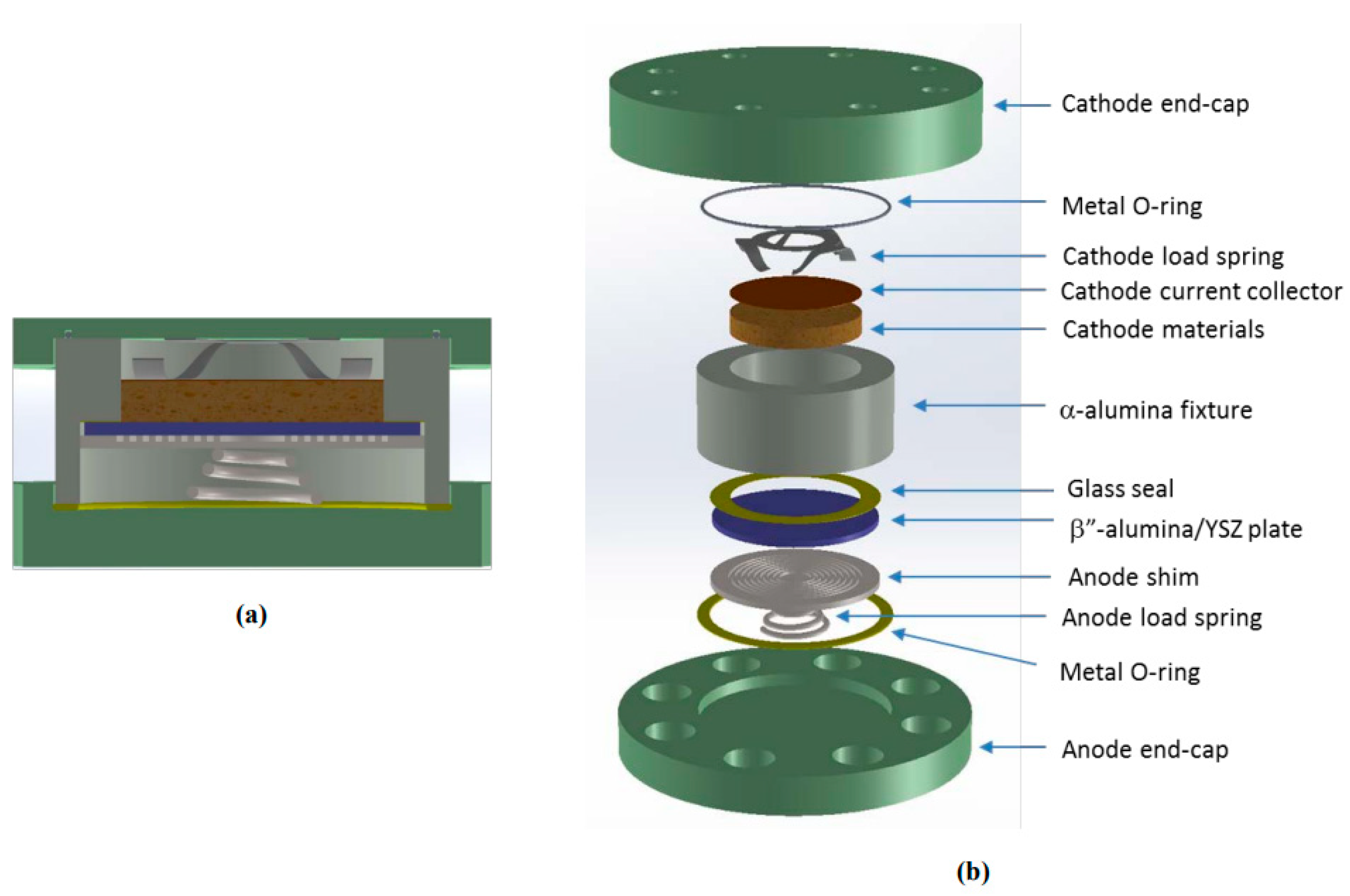
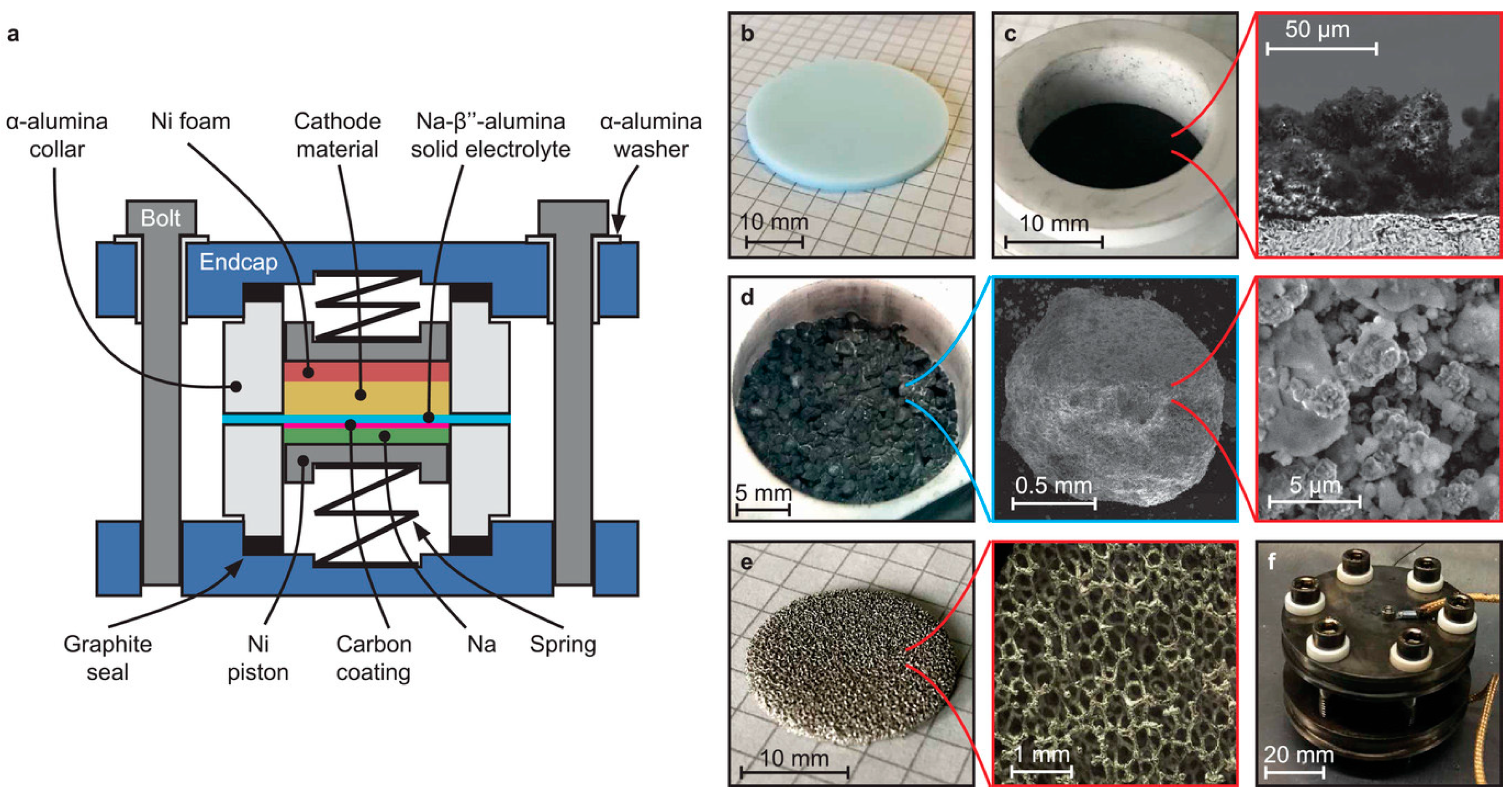
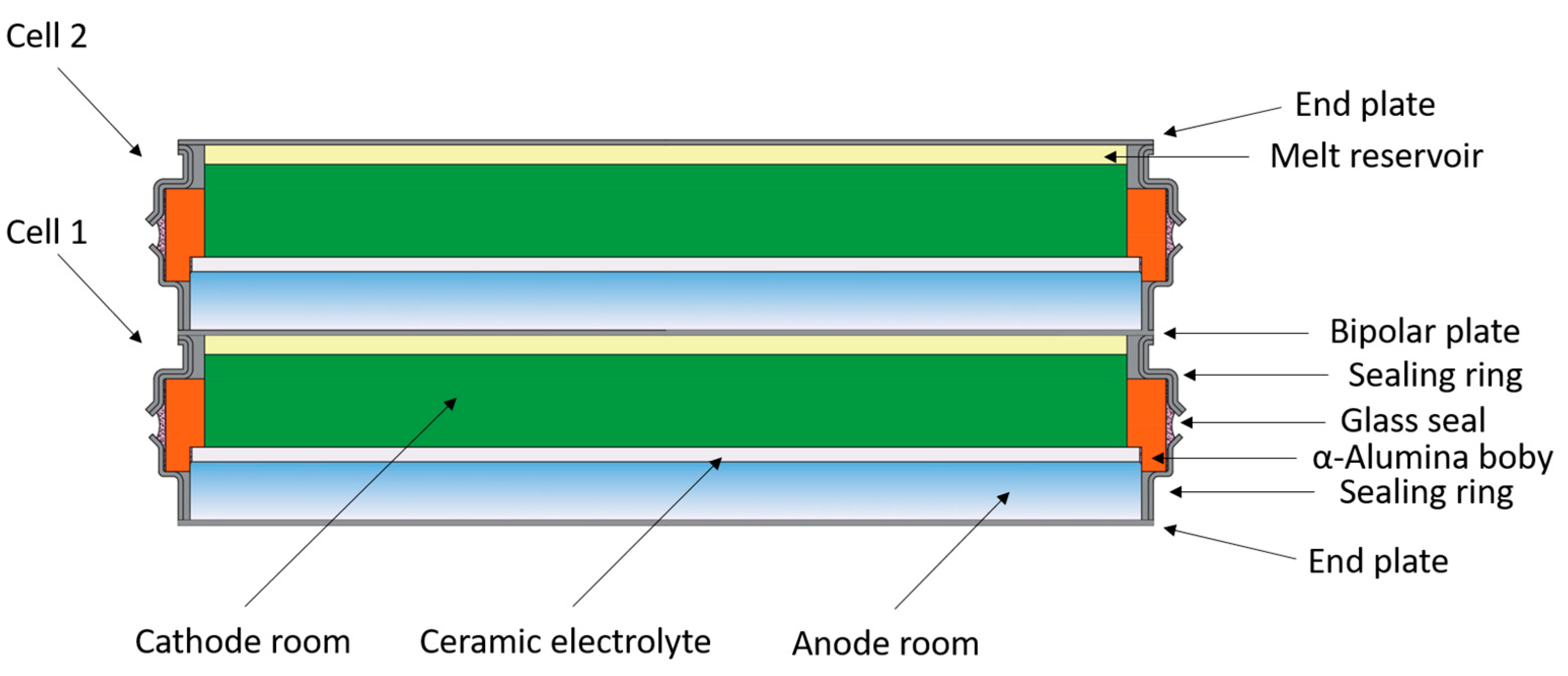
The tubular cell design discussed in Section 4.2 is the only one currently used in the production of commercial ZEBRA batteries. The reasons for this are the good electrical performance, excellent safety and reliability conferred by this design to the final battery system. Nevertheless, the cell performances could be improved by introducing new expedients simply acting on the configuration.
The typical tubular ZEBRA cell employs a central cathode configuration, in which the active material in the form of millimeter-sized grains is placed into the β″-alumina tube and then vacuum-impregnated with molten salt. The inner volume of the ceramic tube, restricted by manufacturing requirements based on mechanical stability, limits the amount of active cathode material and thus the capacity of the cell. Moreover, the design of the closed-end tube allows performing the impregnation process only from the upper side. In this configuration, bubble formation can take place when the vacuum is applied, making the impregnation procedure quite tricky.
To overcome all these drawbacks, a new cell configuration inspired by the first generation of tubular design has been proposed in a recent patent [198]. It comprises a housing with a hemispherical base, where a second opening at the bottom helps the filling with molten salt. Figure 16 shows a schematic drawing according to the invention. It is a central sodium configuration, which comprises a ceramic electrolyte tube with a hemispherical closed end, a cathode space arranged outside of the ceramic electrolyte, and an anode space located inside, while a shim metal tube forms a capillary gap with respect to the internal wall of the ceramic electrolyte. The shim tube extends from the beginning of the cylindrical part of the ceramic tube up to the top, where it narrows to a relatively small diameter. As a result, the molten sodium can rise along the walls of the ceramic tube up to the height where the capillary gap widens. In this way, the glass seal between the electrolyte tube and the ceramic support ring is not wet with liquid sodium, which extends the lifetime of the seal. At the top of the cell housing, there is an opening into which the active mass in the form of dry granular material is placed, and then an annular cap closes the cell. At the round-bottom end of the housing, a second opening serves for the vacuum impregnation of the active mass. Both openings are hermetically sealed after the filling and impregnation processes have been completed. It is worth noting that the use of an external cathode configuration imposes the cell housing to be produced from a metal whose electrical potential is the same or lower than nickel to avoid the corrosion and dissolution of undesirable species at the cathode side.
One of the main concerns of using ZEBRA batteries is related to proper thermal management. For these batteries, which are typically made by packing tens of elementary cells, the optimal operating temperature is about 260–270 °C, although it can increase significantly during discharge at a high current rate. The traditional cooling systems based on fans reduce the temperature unevenly, while the heat is dispersed without any recovery.
Another issue of the traditional tubular cell is that the distance between the positive current collector and the internal surface of the ceramic electrolyte tube is not constant along the tube. Due to this variable distance, the ion exchange does not optimally take place as would be desirable, limiting the overall efficiency of the cell. As a solution, a recent patent proposed an improved tubular cell design, which is a direct evolution of that traditionally used in current commercial batteries [199]. According to the invention, the main difference in the cell design lies in the positive current collector, which consists of a hollow body made of nickel or any suitable nickel-coated metal. The cavity of the collector can be filled with phase-change materials (PCMs), which are able to absorb the excess heat during discharge and release it when needed. The PCMs are chosen to have a phase transition temperature in the range between 250 °C and 350 °C. The presence of the PCMs avoids dangerous temperature increases, also allowing the recovery of excess of heat. This maximizes the uniformity of temperature between the various cells since the temperature trend of each cell is regulated by the local accumulation and release of the heat by PCMs.
A further advantageous feature proposed in the same patent is that the current collector configuration has a constant distance at each point from the tubular ceramic electrolyte. As clearly represented in Figure 17, the ceramic tube and the current collector repeat the same shape with different sized sections. Thanks to this arrangement, the ion exchange can take place in a constant uniform way along the cell. The arrangement of PCMs inside the current collector, in combination with its optimized geometry, improves both the thermal management and internal resistance of the cell, increasing the global energy efficiency of the battery.
Beyond sophisticated cell configurations designed with the final application in mind, the availability of systems that are simple and practical to use is much more useful in the experimental phase. However, in order to carry out accurate studies aimed at investigating the performance of cathode materials, electrolytes or other components, it is important that the cell setup ensures effective and reproducible execution of the test, eliminating any influencing factor that could alter the result. In this context, an interesting tubular cell prototype has recently been proposed by Ahn et al. [200]. Based on the issues encountered with a previous test cell, shown in Figure 18a [60], they redesigned a simple tubular cell prototype optimized for the investigation of sodium-metal chloride battery cathodes. As shown in Figure 18b,c, the simple test cell consisted of a β″-alumina ceramic, a nickel current collector, a cell case, a sodium-metal anode and the cathode material. The β″-alumina ceramic tube, the outside surface of which was coated with carbon paste to improve the wettability of the sodium melt, was placed in the tubular nickel case, while additional metal sodium was used to fill in the gap between ceramic tube and the external case. A nickel rod used as positive current collector was settled centrally within the ceramic tube by suitable bottom stands designed for keeping its position in the middle of the tube. The regular gap between the nickel rod and the ceramic tube was filled with cathode granules and secondary electrolytes. The most interesting feature of this configuration is the easy method of sealing the cell. Instead of the permanent glass seal used in commercial cells, a simple Teflon cap and a hose clamp were applied for closing the package. The high-temperature thermal expansion of the Teflon cap naturally closes the gaps between the different cell elements, ensuring the effective sealing while being also chemically stable against the active species. It was shown that the proposed simple cell setup minimizes the variability in results associated with manual device assembly, thus improving the reproducibility of test execution. In addition, life-cycle tests were less affected by cell setup issues, allowing a more effective assessment of the stability of the battery’s active materials.

4.4. Planar Design

Currently, commercial Na-NiCl2 batteries are manufactured by exclusively employing single cells of tubular geometry. As discussed above, this design has the advantages of reducing the mechanical stress acting on the ceramic electrolyte, thanks to the small joint area at the upper header side that facilitates the sealing and makes the scalability of the cell capacity more feasible. Nevertheless, this design presents many limitations, such as the complex manufacturing of tubular ceramic electrolytes, high production costs, low power density due to a high area-specific resistance (ASR) and cumbersome battery packs because of the low energy density of the single cell.
On the other hand, a planar cell design has several advantages over a tubular design. First, the larger active area of the ceramic electrolyte per unit cell weight increases its power and energy density. Moreover, the planar design simplifies the stacking, and allows a direct inter-cell connection without any external connectors and the use of a thinner solid electrolyte with higher ionic conductivity, with better heat dissipation capability and potentially lower manufacturing costs [201].
The first prototype of a planar molten sodium cell was patented in 1970 by Sudworth [202]. This was a sodium-sulfur cell, in which the electrochemical reactants are liquid sodium at the anode and liquid sulfur at the cathode. The same cell design, in which the sodium-sulfur cathode is replaced with sodium-nickel chloride, represents the conceptual basis for the subsequent development of planar Na-NiCl2 cells. The cell comprised an annular ceramic body whose bottom and top ends were both sealed with two metal plates (Figure 19). It was fabricated from sintered α-alumina to be rigid, impermeable, resistant to attack from the sodium and cathode material and electronically insulating. The inner part of the annular body was separated into two compartments by a ceramic ion conductive membrane made of β″-alumina, which was joined to the holder of α-alumina by a sealing glass compatible with the membrane and the ceramic unit. To provide an electronically conducting path between the electrolyte membrane and the positive current collector, a matrix of carbon felt was located in the cathode compartment, in which the active material was impregnated. To meet the requirements of mechanical stability of the thin β″-alumina membrane (1–1.5 mm thick), the size of the patented cell was limited to have the anode compartment 4.5 mm deep and 35 mm in diameter, and the cathode compartment 2.6 mm deep and 22 mm in diameter. The end plates, made of stainless steel plated with a suitable metal layer, were sealed to the body by graphite or aluminum gaskets. Furthermore, the planar cell geometry was designed to stack multiple cells end to end in electrical series to have a higher battery voltage. According to this configuration, every single plate disposed between adjacent cells constituted a bipolar electrode serving as an end plate for both cells. Flexible bipolar plates with thicknesses of less than 0.13 mm were also designed to compensate for volume changes in the anode and cathode compartments during the charge and discharge processes.
Despite the potentiality of the planar cell design, it was out of consideration for a long time, attracting new interest only in the last decade. In this regard, a fundamental work on planar sodium-metal halide cells was carried out at PNNL by Lemmon and Sprenkle’s team. They presented and patented the first prototype of a planar sodium-nickel chloride cell in 2010 [175,203], whose conceptual design closely resembles the previous sodium-sulfur cell. It consisted of an annular α-alumina body in which a 1 mm thick β″-alumina disc, with a limited diameter of 26 mm (with an effective active area of about 3 cm2), was glass-sealed to the ceramic unit to separate the cell in an anode and a cathode compartment. At the anode side, a metal shim and copper wool, which filled the gap between the electrolyte and shim, allowed the molten sodium to be closely in contact with the β″-alumina disc, also improving sodium utilization. At the cathode side, the active material used for filling was in the form of granules infiltrated with molten NaAlCl4, while a Ni mesh connected to a Ni wire and embedded into the granules served as a current collector. The anode and cathode compartments were finally sealed by stainless steel end plates compressed to the α-alumina body with the help of aluminum washers.
A similar planar cell design was also suggested by Kim et al. [204]. They demonstrated the importance of using an excess of Ni powder together with a Ni mesh at the cathode side to solve the problem related to the low electrical conductivity. Nevertheless, many other performance limitations remained with the use of this simple planar design. In this regard, the extensive studies carried out at PNNL led to better-optimized planar cell prototypes. For instance, Figure 20 shows a conceptual drawing of an advanced planar cell reported by Li et al. [46].
The main difference compared to the previous versions consisted of using preload springs placed on both the anode and cathode sides, with the purpose of keeping the molten sodium on one side and the positive active matter on the other side in good contact with the β″-alumina disc. Moreover, this configuration can compensate the volume variations in the two compartments during the charge and discharge of the cell. A molybdenum disc was used as a positive current collector due to the electrochemical stability of this metal under the operating conditions at the cathode side [205], while a stainless steel disc with machined grooves was used as a current collector at the anode side to retain the molten sodium. A detailed description of this cell configuration is also reported in a dedicated patent [206]. Therein, a way to improve the contact of molten sodium with the ceramic electrolyte by the deposition of a metallic layer made of multiple circular or rectangular elements on the solid electrolyte surface at the anode side is also illustrated. These elements accumulate the molten sodium during the operation of the cell, forming distinct metal islands that expand the area of the anode in active contact with the solid electrolyte. Although the proposed method can be suitable for the metallization with different metals, a Pb/PbO mixture was suggested as a preferable choice to improve the sodium wetting on the surface of the ceramic electrolyte.
A planar cell architecture for lab-scale testing (active area 3.14 cm2) was also presented by Graeber et al. [207]. The conceptual drawing of the cell cross-section and the details of its parts are shown in Figure 21.
The cell consisted of two α-alumina collars with an inner diameter of 20 mm and a 1 mm thick β″-alumina disc sealed between the two collars using a high-temperature sealing glass. The anode side of the β″-alumina disc was coated with a 50 μm thick layer of porous carbon obtained by spraying a suspension of carbon black on the electrolyte surface, then dried at 280 °C to remove the solvents. In the cathode compartment, a rigid Ni foam served as both a current collector and NaAlCl4 reservoir, while spring-loaded Ni pistons at the anode and cathode side compensated the volume change during the charge–discharge of the cell. The entire assembly was enclosed between two stainless steel plates using six stainless steel bolts and alumina washers for electrical insulation. To bypass the electrical resistance of the springs, Ni wires were used as electrical bridges between Ni pistons and the top and bottom end plates. Finally, graphite gaskets, placed between the α-alumina collars and the top and bottom plates, were used to ensure the sealing of the cell. This work also demonstrated the advantages of using a cathode material in the form of pressed granules of millimeter size compared to a single and dense pellet. Indeed, it was claimed that the use of a dense pellet hinders the diffusion of the molten NaAlCl4 electrolyte, limiting the transport of Na-ions in the cathode and causing a drastic increase in cell resistance, especially at a high SOC.
Regarding the development of large planar molten sodium batteries, an important activity was carried out by Dustmann’s team at the Battery Consult. They have presented and patented a simpler planar cell suitable for easy use in the construction of battery stacks [208,209]. Similar to the previous prototypes, the single cell consisted of an α-alumina ring in which a glass-sealed ceramic electrolyte disc separates the anode and cathode compartments. The main difference lies in the seal used, which was made by a glass sealant placed between the α-alumina body and two metal rings arranged along its outer circumference (Figure 22). The design and the coefficient of thermal expansion of these metal rings were chosen to induce positive mechanical stress on the sealing glass at all operating temperatures within 400 °C. The closing end plates, laser-welded to the metal rings, acted as bipolar plates between the cathode of one cell and the anode of the adjacent cell to facilitate stacking for the battery assembly. A further expedient proposed for this cell configuration was the presence of mechanical support for the β″-alumina disc. This consisted of a simple aluminum grid, placed in the anodic compartment and directly in contact with the ceramic separator, whose holes with diameter between 1 and 3 mm form channels that allow the molten sodium to be transported by capillarity to the electrolyte surface. Unlike what was suggested by Graeber et al., here the use of a single tablet made by pressing the active material premixed with a suitable amount of NaAlCl4 powder was proposed [208]. The advantage of this method was to avoid the vacuum infiltration step of the molten secondary electrolyte at high temperatures, simplifying the cell assembly.
A similar planar cell design was patented by Tao et al. [210]. They suggested the use of a cathodic material in the form of a single tablet, but with a vacuum infiltration with NaAlCl4 carried out after the formation of the pellet. Furthermore, a similar system was designed for the mechanical support of the ceramic separator. On the other hand, the seal between the α-alumina body and the end plates of the individual cell was made using a more complex TCB welding. Moreover, to avoid the pressure increase in the cell compartments, a sophisticated bellow system was designed to compensate for the volumetric expansions of the active material at the cathode side. Among other features, the incorporation of a texture from micron to millimeter scale on the surface of the β″-alumina disc was also suggested, which has the role of increasing the active area of the electrolyte while simultaneously improving the wettability to the molten species.
Despite several studies and patents demonstrating the potential benefits of using planar cells, these are not yet commercially available. One of the main reasons is the difficulty of making large β″-alumina ceramic membranes with suitable physical–mechanical characteristics to ensure their effective use inside the cell. As mentioned above, in most of the previous works on planar molten sodium cells, the ceramic membrane used had a diameter ranging from 20 to 45 mm, corresponding to an active area from 3 to 16 cm2 [175,204,207]. Therefore, the area of the largest planar cell reported is about 6% of a commercial tubular cell having a clover-leaf-shaped electrolyte tube. An innovative method for the production of large planar β″-alumina discs has been proposed by Ligon et al. [211]. This consisted of a tape-casting process followed by punching and sintering, which allows obtaining membranes with thicknesses of less than 1.5 mm and diameters up to 110 mm. Although a high concentration of organic binders was used to cast the slurry, they reported the fabrication of β″-alumina membranes having high density, the absence of cracks and ionic conductivity comparable to that produced with conventional methods. A further advantage of this technique is that it is scalable and automatable at low cost.
Despite the efforts made to optimize the manufacturing process of large β″-alumina membranes, mechanical instability occurs when the ceramic electrolyte is firmly joined to the other parts of the cell. In fact, during both assembly and operating time, the molten sodium cells undergo continuous thermal cycles that cause the accumulation of mechanical stresses. These originate from the different coefficients of thermal expansion (CTEs) of the various elements, including the sealing glass, ceramic electrolyte, α-alumina body and metallic components. Moreover, the mechanical stress becomes greater as the cell dimensions increase. Computational models based on finite element analysis (FEA) have been reported with the aim of guiding the geometrical design and the choice of materials to reduce the thermo-mechanical stress on the cell elements [40,212]. These studies concluded that aside from the stress resulting from thermal cycles during the normal operating conditions of the cell, the thermal stress generated during the cell assembly, for example in the TCB sealing step, can also be critical. This process can induce cracks on the external surface of the α-alumina body, at the edges of the metal–ceramic interface and on the central region of the β″-alumina separator (Figure 23). Moreover, it was demonstrated that a key role in the accumulation of thermo-mechanical stress is played by the materials adopted for the container of the planar cells [213]. By computational analyses, it was found that the use of aluminum or high CTE stainless steel, such as AISI304, could result in cell failure originating from either cracking in the α-alumina collar or de-bonding of the metal–ceramic interface. On the other hand, ferritic stainless steel with a CTE smaller than 12 × 10−6 K−1, or special Fe-Ni-Co alloys such as Kovar having a comparable CTE to both ceramic parts and the sealing glass, may be the best choice for developing safe and reliable planar cells.
Thermal cycles are not the only cause of mechanical stress on the cell; the chemo-mechanical expansion of the active electrode materials during charge–discharge processes can significantly contribute to the instability of the cell. Indeed, the volume changes of electrode materials, compressing and expanding the inert gas in the hermetically sealed electrode compartments, induce a substantial pressure difference between the cathode and anode sides (ΔPa-c), which results in a mechanical stress acting on the ceramic β″-alumina electrolyte. In the tubular cell, the mechanical stress generated from the ΔPa-c increases linearly with the tube radius, but it is independent of the height of the tube. Therefore, the cell capacity can be effectively increased by changing the height or radius size of the ceramic tube with limited risk for mechanical stability. On the other hand, when subjected to internal pressure, planar cells show a significant mechanical stress on the ceramic electrolyte disc, which increases according to a quadratic relation with its radius. This aspect is particularly important when high-capacity cells are going to be produced. In this regard, Heinz et al. [214] presented a theoretical study linking the effects of the thermal and chemo-mechanical expansion of the active electrode materials by comparing tubular and planar Na-NiCl2 cells. Three different strategies were suggested to reduce the mechanical stress resulting from the ΔPa-c generated during the compression and expansion of the inert gas trapped in the anodic and cathodic compartments. This happened (i) by increasing the temperature at which the electrode compartments are closed; (ii) by applying vacuum during the sealing of the cell; and (iii) by optimizing the cell design to provide a volumetric balance in the electrode compartments. They conclude by suggesting that any strategy to reduce the pressure during planar cell closing represents an effective way to reduce the ΔPa-c to a level where maximum stresses on the solid electrolyte are non-critical.
Following all the above considerations, many other challenges remain to be faced for the fabrication of safe and high-performing molten sodium planar cells for large-scale storage systems.

5. Summary and Conclusions

Compared to the much more popular lithium-ion batteries, molten sodium batteries have lower performance in terms of specific energy and charge–discharge rate capability. Nevertheless, when large energy storage systems are required, they seem to represent the best compromise between cost and performance. Thanks to many advantages such as long cycle life, lower cost and higher safety level, sodium-beta-alumina batteries have gained great interest for stationary and transport applications. Although high-temperature molten sodium batteries have been commercially available for a few decades, their technology has not undergone particular design or performance improvements compared to the first models introduced on the market. However, to keep on being a competitive energy storage technology, it requires continuous advancements in terms of performance and cost reduction. Driven by the new market demands and by the awareness of the potential of sodium-beta-alumina batteries yet to be brought out, the research interest in this field seems to be regained. This is confirmed by the current efforts focusing on identifying alternative cathode materials to reduce or replace expensive nickel, achieving the optimization of operating conditions at low temperatures, and creating a new cell design to improve the overall performance.
Nickel is the main component in the formulation of the current commercial ZEBRA battery. Moreover, it is used in excess with respect to the stoichiometric amount required by the redox reaction to guarantee enough electrical conductivity at the positive electrode. To move beyond the use of expensive nickel, the most pursued strategy is the replacement with lower-cost transition metals such as Fe, Al, Zn and Cu. It was proven that cells based on these cathode chemistries have similar or superior performance compared to the standard Na-NiCl2 cell, in terms of the charge–discharge rate capability or specific capacity. Among the alternative formulations, the Fe-based cathode could potentially fully replace nickel to produce Na-FeCl2 cells, which retain the excellent specific capacity, stability and reliability of current Na-NiCl2 batteries. A further strategy to reduce the excess of nickel in the cathode could be the use of a conductive network made of less expensive and higher performing material. In this context, hybrid cathodes consisting of metal halides and different carbon structures have been representing an excellent solution. In particular, hybrid metal halide–carbon formulations including nanofibers, nanotubes and graphene have proven to be effective in improving nickel utilization up to specific capacities close to the theoretical one, enhancing at the same time the rate capability owing to the high conductivity conferred by these carbon-based structures. According to many studies proving the efficacy of new cathode materials, it is generally agreed that the simplest upgrade in the short to medium term to improve performance and reduce the cost of current ZEBRA batteries is the replacement of the classical cathode composition with more efficient formulations.
The high operating temperature is another relevant drawback of molten sodium batteries. Aside from limiting the overall efficiency of the battery system due to heat dissipation, it also affects its lifetime, accelerating both the degradation of active materials and cell components, which affects safety. The reduction in operating temperature is therefore one of the current trends of the research in this field. Although this issue has been widely explored, many challenges remain to be addressed. For example, the charge–discharge rate capability of the cell is strongly reduced by the lowered ionic conductivity of the β″-alumina ceramic electrolyte and Na wettability at temperatures below 200 °C. Several patents have suggested alternative sodium-ion conductors (e.g., NaSICON) as ceramic electrolytes for molten sodium batteries with promising excellent ionic conductivity at low temperatures. However, there is a lack of scientific investigations proving their effective and reliable use in practical applications. Moreover, despite the large number of works focusing on the development of these new ceramic electrolytes, they are not yet commercially available. This indicates that there is still a lot of work to be done before a new generation of molten sodium batteries operating at intermediate temperatures could be ready for the market.
The introduction of new cell designs could be a further strategy to improve energy storage performance, also meeting cost reduction needs with the use of simpler manufacturing technologies. Since their invention, tubular cells have represented the most effective geometry for molten sodium batteries. The current ZEBRA battery is exclusively assembled with tubular cells with only a few upgrades with respect to the first type commercialized. Although the tubular design guarantees easy manufacturing and effective compartment sealing, together with excellent mechanical stability for the ceramic electrolyte, it limits the attainable maximum specific power and energy. The planar cell design has been extensively studied in the last decade for both Na-MeCl2 and Na-S batteries. Most of the scientific investigations have shown the advantage of planar cells with respect to the tubular design, in particular toward the improvement of power and energy density, also enabled at intermediate operating temperatures. Several patents have also suggested planar designs for molten sodium batteries and manufacturing methods for their production. However, many of the proposed prototypes have small sizes, and the scalability of the device up to the typical capacities of existing tubular cells is often not considered. In fact, large planar cells would face significant problems concerning the mechanical instability of the ceramic electrolyte, in addition to the greater thermo-mechanical stress to which the sealing regions and the related materials would be subjected. Only a few studies have been carried out on this topic, all failing in suggesting effective solutions. Therefore, considering the indisputable advantages of the new cell designs, further efforts should be focused on their scalability as well as on the identification of technological solutions that could make their construction and implementation feasible in the near future.

Funding

This paper was supported by the Italian Ministry of Economic Development in the framework of the “Fondo per la Ricerca di Sistema Elettrico (RdS), Piano Triennale 2019–2021, Progetto Sistemi Elettrochimici per l’accumulo di energia (DIT.AD017)”, and ADP CNR MISE PT 22-24—Accumulo elettrochimico.

Data Availability Statement

No new data were created or analyzed in this study. Data sharing is not applicable to this article.

Conflicts of Interest

The authors declare no conflict of interest. The funders had no role in the design of the study; in the collection, analyses, or interpretation of data; in the writing of the manuscript; or in the decision to publish the results.

References

  1. Larcher, D.; Tarascon, J.-M. Towards Greener and More Sustainable Batteries for Electrical Energy Storage. Nat. Chem. 2015, 7, 19–29. [Google Scholar] [CrossRef] [PubMed]
  2. James Abraham, J.; Arro, C.R.A.; Tariq, H.A.; Kahraman, R.; Al-Qaradawi, S.; Al tahtamouni, T.M.; Shakoor, R.A. Sodium and Lithium Incorporated Cathode Materials for Energy Storage Applications—A Focused Review. J. Power Sources 2021, 506, 230098. [Google Scholar] [CrossRef]
  3. Ellis, B.L.; Nazar, L.F. Sodium and Sodium-Ion Energy Storage Batteries. Curr. Opin. Solid State Mater. Sci. 2012, 16, 168–177. [Google Scholar] [CrossRef]
  4. Karabelli, D.; Singh, S.; Kiemel, S.; Koller, J.; Konarov, A.; Stubhan, F.; Miehe, R.; Weeber, M.; Bakenov, Z.; Birke, K.P. Sodium-Based Batteries: In Search of the Best Compromise Between Sustainability and Maximization of Electric Performance. Front. Energy Res. 2020, 8, 605129. [Google Scholar] [CrossRef]
  5. Usiskin, R.; Lu, Y.; Popovic, J.; Law, M.; Balaya, P.; Hu, Y.-S.; Maier, J. Fundamentals, Status and Promise of Sodium-Based Batteries. Nat. Rev. Mater. 2021, 6, 1020–1035. [Google Scholar] [CrossRef]
  6. Lu, X.; Lemmon, J.P.; Sprenkle, V.; Yang, Z. Sodium-Beta Alumina Batteries: Status and Challenges. JOM 2010, 62, 31–36. [Google Scholar] [CrossRef]
  7. Lu, X.; Li, G.; Kim, J.Y.; Mei, D.; Lemmon, J.P.; Sprenkle, V.L.; Liu, J. Liquid-Metal Electrode to Enable Ultra-Low Temperature Sodium-Beta Alumina Batteries for Renewable Energy Storage. Nat. Commun. 2014, 5, 4578. [Google Scholar] [CrossRef]
  8. Kluiters, E.C.; Schmal, D.; ter Veen, W.R.; Posthumus, K.J.C.M. Testing of a Sodium/Nickel Chloride (ZEBRA) Battery for Electric Propulsion of Ships and Vehicles. J. Power Sources 1999, 80, 261–264. [Google Scholar] [CrossRef]
  9. Capasso, C.; Veneri, O. Experimental Analysis of a Zebra Battery Based Propulsion System for Urban Bus under Dynamic Conditions. Energy Procedia 2014, 61, 1138–1141. [Google Scholar] [CrossRef]
  10. Dustmann, C.-H. Advances in ZEBRA Batteries. J. Power Sources 2004, 127, 85–92. [Google Scholar] [CrossRef]
  11. Sudworth, J.L. Zebra Batteries. J. Power Sources 1994, 51, 105–114. [Google Scholar] [CrossRef]
  12. Shamim, N.; Thomsen, E.C.; Viswanathan, V.V.; Reed, D.M.; Sprenkle, V.L.; Li, G. Evaluating ZEBRA Battery Module under the Peak-Shaving Duty Cycles. Materials 2021, 14, 2280. [Google Scholar] [CrossRef] [PubMed]
  13. Kebede, A.A.; Kalogiannis, T.; Van Mierlo, J.; Berecibar, M. A Comprehensive Review of Stationary Energy Storage Devices for Large Scale Renewable Energy Sources Grid Integration. Renew. Sustain. Energy Rev. 2022, 159, 112213. [Google Scholar] [CrossRef]
  14. Benato, R.; Dambone Sessa, S.; Musio, M.; Palone, F.; Polito, R. Italian Experience on Electrical Storage Ageing for Primary Frequency Regulation. Energies 2018, 11, 2087. [Google Scholar] [CrossRef]
  15. Benato, R.; Cosciani, N.; Crugnola, G.; Dambone Sessa, S.; Lodi, G.; Parmeggiani, C.; Todeschini, M. Sodium Nickel Chloride Battery Technology for Large-Scale Stationary Storage in the High Voltage Network. J. Power Sources 2015, 293, 127–136. [Google Scholar] [CrossRef]
  16. Restello, S.; Lodi, G.; Miraldi, A.K. Sodium Nickel Chloride Batteries for Telecom Application: A Solution to Critical High Energy Density Deployment in Telecom Facilities. In Proceedings of the INTELEC, International Telecommunications Energy Conference (Proceedings), Scottsdale, AZ, USA, 30 September–4 October 2012. [Google Scholar]
  17. Restello, S.; Lodi, G.; Paolin, E. Sodium-Nickel Batteries for Telecom Applications: Design, Performance and Field Operational Overview. In Proceedings of the INTELEC, International Telecommunications Energy Conference (Proceedings), Amsterdam, The Netherlands, 9–13 October 2011. [Google Scholar]
  18. Rossi, F.; Parisi, M.L.; Greven, S.; Basosi, R.; Sinicropi, A. Life Cycle Assessment of Classic and Innovative Batteries for Solar Home Systems in Europe. Energies 2020, 13, 3454. [Google Scholar] [CrossRef]
  19. Accardo, A.; Dotelli, G.; Musa, M.L.; Spessa, E. Life Cycle Assessment of an NMC Battery for Application to Electric Light-Duty Commercial Vehicles and Comparison with a Sodium-Nickel-Chloride Battery. Appl. Sci. 2021, 11, 1160. [Google Scholar] [CrossRef]
  20. Gaillac, L.; Skaggs, D.; Pinsky, N. Sodium Nickel Chloride Battery Performance in a Stationary Application. In Proceedings of the INTELEC, International Telecommunications Energy Conference (Proceedings), Geneva, Switzerland, 10–14 September 2006. [Google Scholar]
  21. Ha, S.; Kim, J.K.; Choi, A.; Kim, Y.; Lee, K.T. Sodium-Metal Halide and Sodium-Air Batteries. ChemPhysChem 2014, 15, 1971–1982. [Google Scholar] [CrossRef]
  22. Hu, Y.; Wu, X.; Wen, Z.; Hou, M.; Yi, B. Challenges and Thoughts on the Development of Sodium Battery Technology for Energy Storage. Chin. J. Eng. Sci. 2021, 23, 94. [Google Scholar] [CrossRef]
  23. Landmann, D.; Svaluto-Ferro, E.; Heinz, M.V.F.; Schmutz, P.; Battaglia, C. Elucidating the Rate-Limiting Processes in High-Temperature Sodium-Metal Chloride Batteries. Adv. Sci. 2022, 9, 2201019. [Google Scholar] [CrossRef]
  24. Zhan, X.; Sepulveda, J.P.; Lu, X.; Bonnett, J.F.; Canfield, N.L.; Lemmon, T.; Jung, K.; Reed, D.M.; Sprenkle, V.L.; Li, G. Elucidating the Role of Anionic Chemistry towards High-Rate Intermediate-Temperature Na-Metal Halide Batteries. Energy Storage Mater. 2020, 24, 177–187. [Google Scholar] [CrossRef]
  25. Li, G.; Lu, X.; Kim, J.Y.; Lemmon, J.P.; Sprenkle, V.L. Cell Degradation of a Na-NiCl2 (ZEBRA) Battery. J. Mater. Chem. A 2013, 1, 14935–14942. [Google Scholar] [CrossRef]
  26. Li, G.; Lu, X.; Kim, J.Y.; Engelhard, M.H.; Lemmon, J.P.; Sprenkle, V.L. The Role of FeS in Initial Activation and Performance Degradation of Na-NiCl2 batteries. J. Power Sources 2014, 272, 398–403. [Google Scholar] [CrossRef]
  27. Wu, T.; He, Q.; Wen, Z.; Ao, X.; Wu, X.; Hu, Y. Enhanced Cycle Performance of a Na/NiCl2 Battery Based on Ni Particles Encapsulated with Ni3S2 Layer. J. Power Sources 2016, 340, 411–418. [Google Scholar] [CrossRef]
  28. Kim, M.; Ahn, C.-W.; Hahn, B.-D.; Jung, K.; Park, Y.-C.; Cho, N.; Lee, H.; Choi, J.-H. Effects of Ni Particle Morphology on Cell Performance of Na/NiCl2 Battery. Met. Mater. Int. 2017, 23, 1234–1240. [Google Scholar] [CrossRef]
  29. Hosseinifar, M.; Petric, A. High Temperature versus Low Temperature Zebra (Na/NiCl2) Cell Performance. J. Power Sources 2012, 206, 402–408. [Google Scholar] [CrossRef]
  30. Prakash, J.; Redey, L.; Vissers, D.R. Electrochemical Behavior of Nonporous Ni/NiCl2 Electrodes in Chloroaluminate Melts. J. Electrochem. Soc. 2002, 147, 502. [Google Scholar] [CrossRef]
  31. Howie, R.C.; Macmillan, D.W. The Conductivity of the Binary Molten Salt System Aluminium Chloride/Sodium Chloride. J. Inorg. Nucl. Chem. 1971, 33, 3681–3686. [Google Scholar] [CrossRef]
  32. Li, G.; Lu, X.; Coyle, C.A.; Kim, J.Y.; Lemmon, J.P.; Sprenkle, V.L.; Yang, Z. Novel Ternary Molten Salt Electrolytes for Intermediate-Temperature Sodium/Nickel Chloride Batteries. J. Power Sources 2012, 220, 193–198. [Google Scholar] [CrossRef]
  33. Reed, D.; Coffey, G.; Mast, E.; Canfield, N.; Mansurov, J.; Lu, X.; Sprenkle, V. Wetting of Sodium on β″-Al2O3/YSZ Composites for Low Temperature Planar Sodium-Metal Halide Batteries. J. Power Sources 2013, 227, 94–100. [Google Scholar] [CrossRef]
  34. Kim, J.Y.; Lemmon, J.P.; Sprenkle, V.L.; Li, G.; Lu, X. Improved Cycling Behavior of ZEBRA Battery Operated at Intermediate Temperature of 175 °C. J. Power Sources 2013, 249, 414–417. [Google Scholar] [CrossRef]
  35. Fertig, M.P.; Skadell, K.; Schulz, M.; Dirksen, C.; Adelhelm, P.; Stelter, M. From High- to Low-Temperature: The Revival of Sodium-Beta Alumina for Sodium Solid-State Batteries. Batter. Supercaps 2022, 5, e202100131. [Google Scholar] [CrossRef]
  36. Koh, W.; Lee, J.; Kim, J.; Lee, S.; Park, D.; Lee, H.; Robins, M.; Eccleston, A.; Bhavaraju, S.; Kim, J. Development of Molten Sodium Battery Using NaSICON Solid Electrolyte Membrane for Stationary and Large-Scale Electrical Energy Storage System. In Electrochemical Society Meeting Abstracts 226; The Electrochemical Society, Inc.: Pennington, NJ, USA, 2014; MA2014-02; p. 624. [Google Scholar] [CrossRef]
  37. Kim, J.; Jo, S.H.; Bhavaraju, S.; Eccleston, A.; Kang, S.O. Low Temperature Performance of Sodium-Nickel Chloride Batteries with NaSICON Solid Electrolyte. J. Electroanal. Chem. 2015, 759, 201–206. [Google Scholar] [CrossRef]
  38. Jo, S.H.; Kim, J.; Kang, S.O.; Kim, J.-S.; Bhavaraju, S. Investigation of Manufacturing Parameters for NaCl–Ni Granule Type Cathodes Used in Low Temperature NaSICON Sodium-Metal Chloride Batteries. J. Alloys Compd. 2016, 665, 288–293. [Google Scholar] [CrossRef]
  39. Jung, K.; Lee, S.; Park, Y.-C.; Kim, C.-S. Finite Element Analysis Study on the Thermomechanical Stability of Thermal Compression Bonding (TCB) Joints in Tubular Sodium Sulfur Cells. J. Power Sources 2014, 250, 1–14. [Google Scholar] [CrossRef]
  40. Jung, K.; Colker, J.P.; Cao, Y.; Kim, G.; Park, Y.-C.; Kim, C.-S. A Thermo-Mechanical Stress Prediction Model for Contemporary Planar Sodium Sulfur (NaS) Cells. J. Power Sources 2016, 324, 665–673. [Google Scholar] [CrossRef]
  41. Hueso, K.B.; Palomares, V.; Armand, M.; Rojo, T. Challenges and Perspectives on High and Intermediate-Temperature Sodium Batteries. Nano Res. 2017, 10, 4082–4114. [Google Scholar] [CrossRef]
  42. Hueso, K.B.; Armand, M.; Rojo, T. High Temperature Sodium Batteries: Status, Challenges and Future Trends. Energy Environ. Sci. 2013, 6, 734–749. [Google Scholar] [CrossRef]
  43. Delmas, C. Sodium and Sodium-Ion Batteries: 50 Years of Research. Adv. Energy Mater. 2018, 8, 1703137. [Google Scholar] [CrossRef]
  44. Wang, Y.; Zhou, D.; Palomares, V.; Shanmukaraj, D.; Sun, B.; Tang, X.; Wang, C.; Armand, M.; Rojo, T.; Wang, G. Revitalising Sodium–Sulfur Batteries for Non-High-Temperature Operation: A Crucial Review. Energy Environ. Sci. 2020, 13, 3848–3879. [Google Scholar] [CrossRef]
  45. Zhan, X.; Li, M.M.; Weller, J.M.; Sprenkle, V.L.; Li, G. Recent Progress in Cathode Materials for Sodium-Metal Halide Batteries. Materials 2021, 14, 3260. [Google Scholar] [CrossRef] [PubMed]
  46. Lu, X.; Sprenkle, V.L.; Li, G.; Canfield, N.L.; Kim, J.Y.; Chang, H.J.; Meinhardt, K.D. Advanced Intermediate Temperature Sodium–Nickel Chloride Batteries with Ultra-High Energy Density. Nat. Commun. 2016, 7, 10683. [Google Scholar] [CrossRef]
  47. Ratke, L.; Voorhees, P.W. Growth and Coarsening: Ostwald Ripening in Materials Processing. Choice Rev. Online 2002, 39, 39-6445. [Google Scholar] [CrossRef]
  48. Prakash, J.; Redey, L.; Vissers, D.R. Morphological Considerations of the Nickel Chloride Electrodes for Zebra Batteries. J. Power Sources 1999, 84, 63–69. [Google Scholar] [CrossRef]
  49. Bones, R.J.; Teagle, D.A.; Brooker, S.D.; Cullen, F.L. Development of a Ni, NiCl2 Positive Electrode for a Liquid Sodium (ZEBRA) Battery Cell. J. Electrochem. Soc. 1989, 136, 1274–1277. [Google Scholar] [CrossRef]
  50. Prakash, J.; Redey, L.; Vissers, D.R. Effect of Chemical Additives on the Performance of Na/NiCl2 Cells. Ionics 2000, 6, 210–217. [Google Scholar] [CrossRef]
  51. Ratnakumar, B.V.; Surampudi, S.; Halpert, G. Effects of Sulfur Additive on the Performance of Na/NiCl2 Cells. J. Power Sources 1994, 48, 349–360. [Google Scholar] [CrossRef]
  52. Lu, X.; Lemmon, J.P.; Kim, J.Y.; Sprenkle, V.L.; Yang, Z. High Energy Density Na-S/NiCl2 Hybrid Battery. J. Power Sources 2013, 224, 312–316. [Google Scholar] [CrossRef]
  53. Prakash, J.; Redey, L.; Vissers, D.R.; DeGruson, J. Effect of Sodium Iodide Additive on the Electrochemical Performance of Sodium/Nickel Chloride Cells. J. Appl. Electrochem. 2000, 30, 1229–1233. [Google Scholar] [CrossRef]
  54. Chang, H.J.; Canfield, N.L.; Jung, K.; Sprenkle, V.L.; Li, G. Advanced Na-NiCl2 Battery Using Nickel-Coated Graphite with Core-Shell Microarchitecture. ACS Appl. Mater. Interfaces 2017, 9, 11609–11614. [Google Scholar] [CrossRef]
  55. Chang, H.J.; Lu, X.; Bonnett, J.F.; Canfield, N.L.; Son, S.; Park, Y.C.; Jung, K.; Sprenkle, V.L.; Li, G. “Ni-Less” Cathodes for High Energy Density, Intermediate Temperature Na-NiCl2 Batteries. Adv. Mater. Interfaces 2018, 5, 1701592. [Google Scholar] [CrossRef]
  56. Bones, R.J.; Coetzer, J.; Galloway, R.C.; Teagle, D.A. A Sodium/Iron(II) Chloride Cell with a Beta Alumina Electrolyte. J. Electrochem. Soc. 1987, 134, 2379–2382. [Google Scholar] [CrossRef]
  57. Li, G.; Lu, X.; Kim, J.Y.; Viswanathan, V.V.; Meinhardt, K.D.; Engelhard, M.H.; Sprenkle, V.L. An Advanced Na-FeCl2 ZEBRA Battery for Stationary Energy Storage Application. Adv. Energy Mater. 2015, 5, 1500357. [Google Scholar] [CrossRef]
  58. Zhan, X.; Bowden, M.E.; Lu, X.; Bonnett, J.F.; Lemmon, T.; Reed, D.M.; Sprenkle, V.L.; Li, G. A Low-Cost Durable Na-FeCl2 Battery with Ultrahigh Rate Capability. Adv. Energy Mater. 2020, 10, 1903472. [Google Scholar] [CrossRef]
  59. Ahn, C.-W.; Kim, M.; Hahn, B.-D.; Hong, I.; Kim, W.; Moon, G.; Lee, H.; Jung, K.; Park, Y.-C.; Choi, J.-H. Microstructure Design of Metal Composite for Active Material in Sodium Nickel-Iron Chloride Battery. J. Power Sources 2016, 329, 50–56. [Google Scholar] [CrossRef]
  60. Ahn, B.-M.; Ahn, C.-W.; Hahn, B.-D.; Choi, J.-J.; Kim, Y.-D.; Lim, S.-K.; Jung, K.; Park, Y.-C.; Choi, J.-H. Easy Approach to Realize Low Cost and High Cell Capacity in Sodium Nickel-Iron Chloride Battery. Compos. Part B Eng. 2019, 168, 442–447. [Google Scholar] [CrossRef]
  61. Ahn, B.-M.; Ahn, C.-W.; Hahn, B.-D.; Choi, J.-J.; Kim, Y.-D.; Lim, S.-K.; Choi, J.-H. Effect of Cathode Microstructure on Electrochemical Properties of Sodium Nickel-Iron Chloride Batteries. Materials 2021, 14, 5605. [Google Scholar] [CrossRef]
  62. Frusteri, L.; Leonardi, S.G.; Samperi, M.; Antonucci, V.; D’Urso, C. Characterization and Testing of Cathode Materials for High Temperature Sodium Nickel-ironchloride Battery. J. Energy Storage 2022, 55, 105503. [Google Scholar] [CrossRef]
  63. Xue, L.; Xin, S.; Goodenough, J.B.; Angell, C.A. An Inverse Aluminum Battery: Putting the Aluminum as the Cathode. ACS Energy Lett. 2017, 2, 1534–1538. [Google Scholar] [CrossRef]
  64. Zhan, X.; Bonnett, J.F.; Engelhard, M.H.; Reed, D.M.; Sprenkle, V.L.; Li, G. A High-Performance Na-Al Battery Based on Reversible NaAlCl4 Catholyte. Adv. Energy Mater. 2020, 10, 2001378. [Google Scholar] [CrossRef]
  65. Lee, Y.; Kim, H.-J.; Byun, D.-J.; Cho, K.-K.; Ahn, J.-H.; Kim, C.-S. Electrochemically Activated Na-ZnCl2 Battery Using a Carbon Matrix in the Cathode Compartment. J. Power Sources 2019, 440, 227110. [Google Scholar] [CrossRef]
  66. Lu, X.; Li, G.; Kim, J.Y.; Lemmon, J.P.; Sprenkle, V.L.; Yang, Z. A Novel Low-Cost Sodium–Zinc Chloride Battery. Energy Environ. Sci. 2013, 6, 1837. [Google Scholar] [CrossRef]
  67. Sprenkle, V.L.; Lu, X.; Jung, K.; Chang, H.J.; Canfield, N.L.; Li, G.; Bonnett, J.F. An Intermediate-Temperature High-Performance Na-ZnCl2 Battery. ACS Omega 2018, 3, 15702–15708. [Google Scholar] [CrossRef]
  68. Ratnakumar, B.V.; Di Stefano, S.; Halpert, G. Electrochemistry of Metal Chloride Cathodes in Sodium Batteries. J. Electrochem. Soc. 1990, 137, 2991–2997. [Google Scholar] [CrossRef]
  69. Pye, S.; Winnick, J.; Kohl, P.A. Iron, Copper, and Nickel Behavior in Buffered, Neutral Aluminum Chloride: 1-Methyl-3-ethylimidazolium Chloride Molten Salt. J. Electrochem. Soc. 1997, 144, 1933–1938. [Google Scholar] [CrossRef]
  70. Chen, P.-Y.; Sun, I.-W. Electrochemical Study of Copper in a Basic 1-Ethyl-3-Methylimidazolium Tetrafluoroborate Room Temperature Molten Salt. Electrochim. Acta 1999, 45, 441–450. [Google Scholar] [CrossRef]
  71. Kim, B.R.; Jeong, G.; Kim, A.; Kim, Y.; Kim, M.G.; Kim, H.; Kim, Y.J. High Performance Na-CuCl2 Rechargeable Battery toward Room Temperature ZEBRA-Type Battery. Adv. Energy Mater. 2016, 6, 1600862. [Google Scholar] [CrossRef]
  72. Niu, C.; Zhang, Y.; Ma, S.; Wan, Y.; Yang, H.; Liu, X. An Intermediate Temperature Sodium Copper Chloride Battery Using Ionic Liquid Electrolyte and Its Degradation Mechanism. Ionics 2019, 25, 4189–4196. [Google Scholar] [CrossRef]
  73. Niu, C.; Ji, L.; Chen, Y.; Ma, S.; Zhang, Y.; Liu, X.; Yang, H. Low-Melting-Point Ionic Liquid Electrolyte for an Intermediate-Temperature Sodium–Copper Chloride Battery. Energy Fuels 2021, 35, 12538–12545. [Google Scholar] [CrossRef]
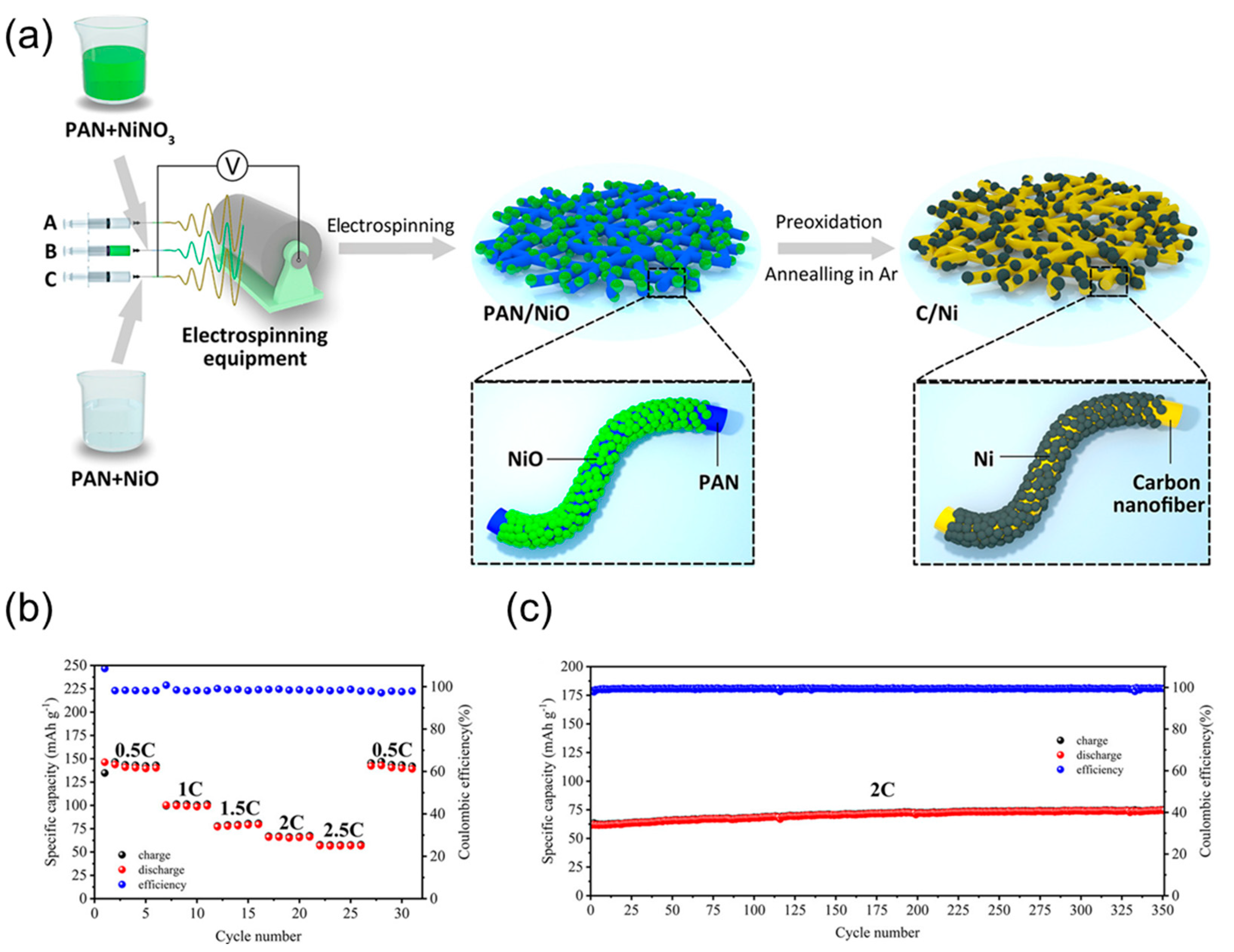
  74. Gao, X.; Hu, Y.; Li, Y.; Wang, J.; Wu, X.; Yang, J.; Wen, Z. High-Rate and Long-Life Intermediate-Temperature Na-NiCl2 Battery with Dual-Functional Ni–Carbon Composite Nanofiber Network. ACS Appl. Mater. Interfaces 2020, 12, 24767–24776. [Google Scholar] [CrossRef]
  75. Li, Y.; Shi, L.; Gao, X.; Wang, J.; Hu, Y.; Wu, X.; Wen, Z. Constructing a Charged-State Na-NiCl2 Battery with NiCl2/Graphene Aerogel Composite as Cathode. Chem. Eng. J. 2021, 421, 127853. [Google Scholar] [CrossRef]
  76. Li, Y.; Wu, X.; Wang, J.; Gao, X.; Hu, Y.; Wen, Z. Ni-Less Cathode with 3D Free-Standing Conductive Network for Planar Na-NiCl2 Batteries. Chem. Eng. J. 2020, 387, 124059. [Google Scholar] [CrossRef]
  77. Gerovasili, E.; May, J.F.; Sauer, D.U. Experimental Evaluation of the Performance of the Sodium Metal Chloride Battery below Usual Operating Temperatures. J. Power Sources 2014, 251, 137–144. [Google Scholar] [CrossRef]
  78. Lu, X.; Li, G.; Kim, J.Y.; Lemmon, J.P.; Sprenkle, V.L.; Yang, Z. The Effects of Temperature on the Electrochemical Performance of Sodium-Nickel Chloride Batteries. J. Power Sources 2012, 215, 288–295. [Google Scholar] [CrossRef]
  79. Yao, Y.-F.Y.; Kummer, J.T. Ion Exchange Properties of and Rates of Ionic Diffusion in Beta-Alumina. J. Inorg. Nucl. Chem. 1967, 29, 2453–2475. [Google Scholar] [CrossRef]
  80. Chi, C.; Katsui, H.; Goto, T. Effect of Li Addition on the Formation of Na-β/β″-Alumina Film by Laser Chemical Vapor Deposition. Ceram. Int. 2017, 43, 1278–1283. [Google Scholar] [CrossRef]
  81. Beckers, J. Ionic Conduction in Na+-β-Alumina Studied by Molecular Dynamics Simulation. Solid State Ionics 2000, 133, 217–231. [Google Scholar] [CrossRef]
  82. Stevens, R.; Binner, J.G.P. Structure, Properties and Production of β-Alumina. J. Mater. Sci. 1984, 19, 695–715. [Google Scholar] [CrossRef]
  83. Birnie, D.P. On the Structural Integrity of the Spinel Block in the β″-Alumina Structure. Acta Crystallogr. Sect. B Struct. Sci. 2012, 68, 118–122. [Google Scholar] [CrossRef]
  84. Yang, Z.; Zhang, J.; Kintner-Meyer, M.C.W.; Lu, X.; Choi, D.; Lemmon, J.P.; Liu, J. Electrochemical Energy Storage for Green Grid. Chem. Rev. 2011, 111, 3577–3613. [Google Scholar] [CrossRef]
  85. Koganei, K.; Oyama, T.; Inada, M.; Enomoto, N.; Hayashi, K. C-Axis Oriented β″-Alumina Ceramics with Anisotropic Ionic Conductivity Prepared by Spark Plasma Sintering. Solid State Ionics 2014, 267, 22–26. [Google Scholar] [CrossRef]
  86. Li, K.; Yang, Y.; Zhang, X.; Liang, S. Highly Oriented Β″-Alumina Ceramics with Excellent Ionic Conductivity and Mechanical Performance Obtained by Spark Plasma Sintering Technique. J. Mater. Sci. 2020, 55, 8435–8443. [Google Scholar] [CrossRef]
  87. Liang, S.; Yang, Y.; Li, K.; Zhang, X. A Study on the Preparation of Oriented Beta″-Alumina Ceramics Using Rod/Flake-like Boehmite as Precursors and Their Properties. J. Eur. Ceram. Soc. 2020, 40, 4047–4055. [Google Scholar] [CrossRef]
  88. Kim, J.Y.; Canfield, N.L.; Bonnett, J.F.; Sprenkle, V.L.; Jung, K.; Hong, I. A Duplex β″-Al2O3 Solid Electrolyte Consisting of a Thin Dense Layer and a Porous Substrate. Solid State Ionics 2015, 278, 192–197. [Google Scholar] [CrossRef]
  89. Canfield, N.L.; Kim, J.Y.; Bonnett, J.F.; Pearson, R.L.; Sprenkle, V.L.; Jung, K. Effects of Fabrication Conditions on Mechanical Properties and Microstructure of Duplex β″-Al2O3 Solid Electrolyte. Mater. Sci. Eng. B 2015, 197, 43–50. [Google Scholar] [CrossRef]
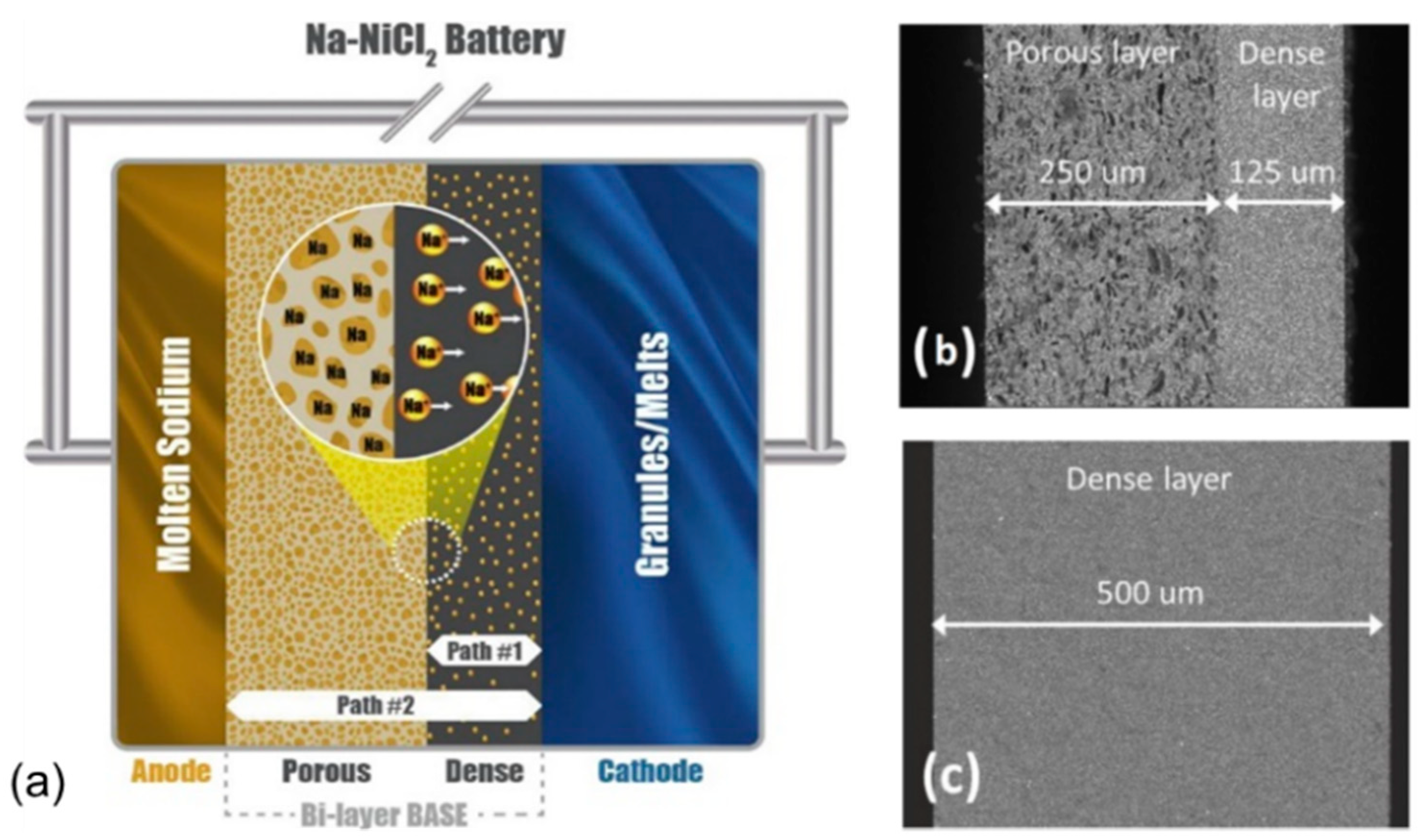
  90. Jung, K.; Chang, H.J.; Bonnett, J.F.; Canfield, N.L.; Sprenkle, V.L.; Li, G. An Advanced Na-NiCl2 Battery Using Bi-Layer (Dense/Micro-Porous) β″-Alumina Solid-State Electrolytes. J. Power Sources 2018, 396, 297–303. [Google Scholar] [CrossRef]
  91. Wen, Z.; Gu, Z.; Xu, X.; Cao, J.; Zhang, F.; Lin, Z. Research Activities in Shanghai Institute of Ceramics, Chinese Academy of Sciences on the Solid Electrolytes for Sodium Sulfur Batteries. J. Power Sources 2008, 184, 641–645. [Google Scholar] [CrossRef]
  92. Dirksen, C.L.; Skadell, K.; Schulz, M.; Fertig, M.P.; Stelter, M. Influence of 3d Transition Metal Doping on Lithium Stabilized Na-β″-Alumina Solid Electrolytes. Materials 2021, 14, 5389. [Google Scholar] [CrossRef]
  93. Fertig, M.P.; Dirksen, C.; Schulz, M.; Stelter, M. Humidity-Induced Degradation of Lithium-Stabilized Sodium-Beta Alumina Solid Electrolytes. Batteries 2022, 8, 103. [Google Scholar] [CrossRef]
  94. Zhu, L.; Virkar, A. V Conversion Kinetics and Ionic Conductivity in Na-β″-Alumina + YSZ (Naβ″AY) Sodium Solid Electrolyte via Vapor Phase Conversion Process. Membranes 2022, 12, 567. [Google Scholar] [CrossRef]
  95. Zhang, G.; Wen, Z.; Wu, X.; Zhang, J.; Ma, G.; Jin, J. Sol-Gel Synthesis of Mg2+ Stabilized Na-β″/β-Al2O3 Solid Electrolyte for Sodium Anode Battery. J. Alloys Compd. 2014, 613, 80–86. [Google Scholar] [CrossRef]
  96. Agustina, A.I.; Skadell, K.; Dirksen, C.L.; Schulz, M.; Kusumocahyo, S.P. Sol-Gel Method for Synthesis of Li+-Stabilized Na-β″-Alumina for Solid Electrolytes in Sodium-Based Batteries. In Proceedings of the AIP Conference Proceedings, Grenoble, France, 8–12 July 2019; p. 020070. [Google Scholar]
  97. Li, H.; Fan, H.; Wang, B.; Wang, C.; Zhang, M.; Chen, G.; Jiang, X.; Zhao, N.; Lu, J.; Zhang, J. Mechanical and Electrical Properties of Lithium Stabilized Sodium Beta Alumina Solid Electrolyte Shaping by Non-Aqueous Gelcasting. J. Eur. Ceram. Soc. 2020, 40, 3072–3079. [Google Scholar] [CrossRef]
  98. Mathews, T. Solution Combustion Synthesis of Magnesium Compensated Sodium-β-Aluminas. Mater. Sci. Eng. B 2000, 78, 39–43. [Google Scholar] [CrossRef]
  99. Mali, A.; Petric, A. Synthesis of Sodium β″-Alumina Powder by Sol–Gel Combustion. J. Eur. Ceram. Soc. 2012, 32, 1229–1234. [Google Scholar] [CrossRef]
  100. Sutorik, A.C.; Neo, S.S.; Treadwell, D.R.; Laine, R.M. Synthesis of Ultrafine β″-Alumina Powders via Flame Spray Pyrolysis of Polymeric Precursors. J. Am. Ceram. Soc. 2005, 81, 1477–1486. [Google Scholar] [CrossRef]
  101. Ghadbeigi, L.; Szendrei, A.; Moreno, P.; Sparks, T.D.; Virkar, A.V. Synthesis of Iron-Doped Na-β″-Alumina + Yttria-Stabilized Zirconia Composite Electrolytes by a Vapor Phase Process. Solid State Ionics 2016, 290, 77–82. [Google Scholar] [CrossRef]
  102. Park, H.C.; Lee, Y.B.; Lee, S.G.; Lee, C.H.; Kim, J.K.; Hong, S.S.; Park, S.S. Synthesis of Beta-Alumina Powders by Microwave Heating from Solution-Derived Precipitates. Ceram. Int. 2005, 31, 293–296. [Google Scholar] [CrossRef]
  103. Wei, X.; Xia, Y.; Liu, X.; Yang, H.; Shen, X. Preparation of Sodium Beta″-Alumina Electrolyte Thin Film by Electrophoretic Deposition Using Taguchi Experimental Design Approach. Electrochim. Acta 2014, 136, 250–256. [Google Scholar] [CrossRef]
  104. Zhao, K.; Liu, Y.; Zeng, S.M.; Yang, J.H.; Liu, Y.W.; Zhan, Z.L.; Song, L. Preparation and Characterization of a ZrO2–TiO2-Co-Doped Na-Β″-Al2O3 Ceramic Thin Film. Ceram. Int. 2016, 42, 8990–8996. [Google Scholar] [CrossRef]
  105. Xu, D.; Jiang, H.; Li, Y.; Li, L.; Li, M.; Hai, O. The Mechanical and Electrical Properties of Nb2O5 Doped Na-β″-Al2O3 Solid Electrolyte. Eur. Phys. J. Appl. Phys. 2016, 74, 10901. [Google Scholar] [CrossRef]
  106. Barison, S.; Fasolin, S.; Mortalò, C.; Boldrini, S.; Fabrizio, M. Effect of Precursors on β-Alumina Electrolyte Preparation. J. Eur. Ceram. Soc. 2015, 35, 2099–2107. [Google Scholar] [CrossRef]
  107. Liu, Z.; Chen, J.; Wang, X.; Wang, Y.; Wang, D.; Mao, Z. Synthesis and Characterization of High Ionic-Conductive Sodium Beta-Alumina Solid Electrolyte Derived from Boehmite. J. Mater. Sci. Mater. Electron. 2020, 31, 17670–17678. [Google Scholar] [CrossRef]
  108. Zhu, C.; Xue, J.; Ji, G. Effect of Na2O Content on Properties of Beta Alumina Solid Electrolytes. Mater. Sci. Semicond. Process. 2015, 31, 487–492. [Google Scholar] [CrossRef]
  109. Bay, M.-C.; Heinz, M.V.F.; Figi, R.; Schreiner, C.; Basso, D.; Zanon, N.; Vogt, U.F.; Battaglia, C. Impact of Liquid Phase Formation on Microstructure and Conductivity of Li-Stabilized Na-β″-Alumina Ceramics. ACS Appl. Energy Mater. 2019, 2, 687–693. [Google Scholar] [CrossRef]
  110. Sudworth, J.L.; Barrow, P.; Dong, W.; Dunn, B.; Farrington, G.C.; Thomas, J.O. Toward Commercialization of the Beta-Alumina Family of Ionic Conductors. MRS Bull. 2000, 25, 22–26. [Google Scholar] [CrossRef]
  111. Zhu, C.; Xue, J. Structure and Properties Relationships of Beta-Al2O3 Electrolyte Materials. J. Alloys Compd. 2012, 517, 182–185. [Google Scholar] [CrossRef]
  112. Lee, S.T.; Lee, K.M.; Lee, D.H.; Haw, J.R.; Lim, S.K. Analysis of the Phase Formation of Na-β/β-Aluminas Using MgO and Li2O as Phase Stabilizers. J. Ceram. Process. Res. 2011, 12, 38–45. [Google Scholar]
  113. Chen, G.; Lu, J.; Zhou, X.; Chen, L.; Jiang, X. Solid-State Synthesis of High Performance Na-β″-Al2O3 Solid Electrolyte Doped with MgO. Ceram. Int. 2016, 42, 16055–16062. [Google Scholar] [CrossRef]
  114. Xu, D.; Jiang, H.; Li, M.; Hai, O.; Zhang, Y. Synthesis and Characterization of Y2O3 Doped Na-β″-Al2O3 Solid Electrolyte by Double Zeta Process. Ceram. Int. 2015, 41, 5355–5361. [Google Scholar] [CrossRef]
  115. Li, H.; Fan, H.; Zhang, J.; Wen, Y.; Chen, G.; Zhu, Y.; Lu, J.; Jiang, X.; Hu, B.; Ning, L. Sintering Behavior and Properties of Lithium Stabilized Sodium β″—Alumina Ceramics with YSZ Addition. Ceram. Int. 2019, 45, 6744–6752. [Google Scholar] [CrossRef]
  116. Wu, J.; Shi, J.; Hong, Y.; Zhu, C. Effect of Chromium on Electrochemical and Mechanical Properties of Beta-Al2O3 Solid Electrolyte. Mater. Res. Express 2020, 7, 105502. [Google Scholar] [CrossRef]
  117. Zhu, C.; Hong, Y.; Huang, P. Synthesis and Characterization of NiO Doped Beta-Al2O3 Solid Electrolyte. J. Alloys Compd. 2016, 688, 746–751. [Google Scholar] [CrossRef]
  118. Lee, S.-T.; Lee, D.-H.; Kim, J.-S.; Lim, S.-K. Influence of Fe and Ti Addition on Properties of Na+-β/β″-Alumina Solid Electrolytes. Met. Mater. Int. 2017, 23, 246–253. [Google Scholar] [CrossRef]
  119. Lu, X.; Li, G.; Kim, J.Y.; Meinhardt, K.D.; Sprenkle, V.L. Enhanced Sintering of β″-Al2O3/YSZ with the Sintering Aids of TiO2 and MnO2. J. Power Sources 2015, 295, 167–174. [Google Scholar] [CrossRef]
  120. Lee, D.-H.; Lee, D.-G.; Lim, S.-K. Influence of MnO2 and Ta2O5/YSZ Addition on Properties of Na+−β/β″-Alumina Solid Electrolytes Prepared by a Synthesizing-Cum-Sintering Process. Ceram. Int. 2021, 47, 24743–24751. [Google Scholar] [CrossRef]
  121. Wei, X.; Cao, Y.; Lu, L.; Yang, H.; Shen, X. Synthesis and Characterization of Titanium Doped Sodium Beta″-Alumina. J. Alloys Compd. 2011, 509, 6222–6226. [Google Scholar] [CrossRef]
  122. Wang, C.-J.; Huang, C.-Y. Effect of TiO2 Addition on the Sintering Behavior, Hardness and Fracture Toughness of an Ultrafine Alumina. Mater. Sci. Eng. A 2008, 492, 306–310. [Google Scholar] [CrossRef]
  123. Chen, G.; Lu, J.; Li, L.; Chen, L.; Jiang, X. Microstructure Control and Properties of β″-Al2O3 Solid Electrolyte. J. Alloys Compd. 2016, 673, 295–301. [Google Scholar] [CrossRef]
  124. Dirksen, C.L.; Skadell, K.; Schulz, M.; Stelter, M. Effects of TiO2 Doping on Li+-Stabilized Na-β″-Alumina for Energy Storage Applications. Sep. Purif. Technol. 2019, 213, 88–92. [Google Scholar] [CrossRef]
  125. Lee, D.-G.; Ahn, B.-M.; Ahn, C.-W.; Choi, J.-H.; Lee, D.-H.; Lim, S.-K. Fabrication of a Full-Scale Pilot Model of a Cost-Effective Sodium Nickel-Iron Chloride Battery Over 40 Ah. J. Electrochem. Sci. Technol. 2021, 12, 398–405. [Google Scholar] [CrossRef]
  126. Jin, D.; Choi, S.; Jang, W.; Soon, A.; Kim, J.; Moon, H.; Lee, W.; Lee, Y.; Son, S.; Park, Y.; et al. Bismuth Islands for Low-Temperature Sodium-Beta Alumina Batteries. ACS Appl. Mater. Interfaces 2018, 11, 2917–2924. [Google Scholar] [CrossRef]
  127. Chang, H.-J.; Lu, X.; Bonnett, J.F.; Canfield, N.L.; Han, K.; Engelhard, M.H.; Jung, K.; Sprenkle, V.L.; Li, G. Decorating Β″-Alumina Solid-State Electrolytes with Micron Pb Spherical Particles for Improving Na Wettability at Lower Temperatures. J. Mater. Chem. A 2018, 6, 19703–19711. [Google Scholar] [CrossRef]
  128. Li, M.M.; Lu, X.; Zhan, X.; Engelhard, M.H.; Bonnett, J.F.; Polikarpov, E.; Jung, K.; Reed, D.M.; Sprenkle, V.L.; Li, G. High Performance Sodium-Sulfur Batteries at Low Temperature Enabled by Superior Molten Na Wettability. Chem. Commun. 2021, 57, 45–48. [Google Scholar] [CrossRef]
  129. Sudworth, J.; Tiley, A.R. Sodium Sulphur Battery; Springer Science & Business Media: Berlin/Heidelberg, Germany, 1985; ISBN 0412164906. [Google Scholar]
  130. Hu, Y.; Wen, Z.; Wu, X.; Lu, Y. Nickel Nanowire Network Coating to Alleviate Interfacial Polarization for Na-Beta Battery Applications. J. Power Sources 2013, 240, 786–795. [Google Scholar] [CrossRef]
  131. Ahlbrecht, K.; Bucharsky, C.; Holzapfel, M.; Tübke, J.; Hoffmann, M.J. Investigation of the Wetting Behavior of Na and Na Alloys on Uncoated and Coated Na-β″-Alumina at Temperatures below 150 °C. Ionics 2017, 23, 1319–1327. [Google Scholar] [CrossRef]
  132. Goodenough, J.B.; Hong, H.-P.; Kafalas, J.A. Fast Na+-Ion Transport in Skeleton Structures. Mater. Res. Bull. 1976, 11, 203–220. [Google Scholar] [CrossRef]
  133. Tietz, F. Phase Relations of NASICON Materials and Compilation of the Quaternary Phase Diagram Na2O-P2O5-SiO2-ZrO2. AIMS Mater. Sci. 2017, 4, 1305–1318. [Google Scholar] [CrossRef]
  134. Hong, H.-P. Crystal Structures and Crystal Chemistry in the System Na1+xZr2SixP3−xO12. Mater. Res. Bull. 1976, 11, 173–182. [Google Scholar] [CrossRef]
  135. Oh, J.A.S.; He, L.; Plewa, A.; Morita, M.; Zhao, Y.; Sakamoto, T.; Song, X.; Zhai, W.; Zeng, K.; Lu, L. Composite NASICON (Na3Zr2Si2PO12) Solid-State Electrolyte with Enhanced Na+ Ionic Conductivity: Effect of Liquid Phase Sintering. ACS Appl. Mater. Interfaces 2019, 11, 40125–40133. [Google Scholar] [CrossRef]
  136. von Alpen, U.; Bell, M.F.; Wichelhaus, W. Phase Transition in Nasicon (Na3Zr2Si2PO12). Mater. Res. Bull. 1979, 14, 1317–1322. [Google Scholar] [CrossRef]
  137. Lalère, F.; Leriche, J.B.; Courty, M.; Boulineau, S.; Viallet, V.; Masquelier, C.; Seznec, V. An All-Solid State NASICON Sodium Battery Operating at 200 °C. J. Power Sources 2014, 247, 975–980. [Google Scholar] [CrossRef]
  138. Jolley, A.G.; Taylor, D.D.; Schreiber, N.J.; Wachsman, E.D. Structural Investigation of Monoclinic-Rhombohedral Phase Transition in Na3Zr2Si2PO12 and Doped NASICON. J. Am. Ceram. Soc. 2015, 98, 2902–2907. [Google Scholar] [CrossRef]
  139. Song, S.; Duong, H.M.; Korsunsky, A.M.; Hu, N.; Lu, L. A Na+ Superionic Conductor for Room-Temperature Sodium Batteries. Sci. Rep. 2016, 6, 32330. [Google Scholar] [CrossRef] [PubMed]
  140. Guin, M.; Tietz, F.; Guillon, O. New Promising NASICON Material as Solid Electrolyte for Sodium-Ion Batteries: Correlation between Composition, Crystal Structure and Ionic Conductivity of Na3+xSc3SixP3−xO12. Solid State Ionics 2016, 293, 18–26. [Google Scholar] [CrossRef]
  141. Ma, Q.; Guin, M.; Naqash, S.; Tsai, C.L.; Tietz, F.; Guillon, O. Scandium-Substituted Na3Zr2(SiO4)2(PO4) Prepared by a Solution-Assisted Solid-State Reaction Method as Sodium-Ion Conductors. Chem. Mater. 2016, 28, 4821–4828. [Google Scholar] [CrossRef]
  142. Chen, D.; Luo, F.; Zhou, W.; Zhu, D. Influence of Nb5+, Ti4+, Y3+ and Zn3+ Doped Na3Zr2Si2PO12 Solid Electrolyte on Its Conductivity. J. Alloys Compd. 2018, 757, 348–355. [Google Scholar] [CrossRef]
  143. Xie, B.; Jiang, D.; Wu, J.; Feng, T.; Xia, J.; Nian, H. Effect of Substituting Ce for Zr on the Electrical Properties of NASICON Materials. J. Phys. Chem. Solids 2016, 88, 104–108. [Google Scholar] [CrossRef]
  144. Naqash, S.; Tietz, F.; Guillon, O. Synthesis and Characterization of Equimolar Al/Y-Substituted NASICON Solid Solution Na1+2x+yAlxYxZr2−2xSiyP3−yO12. Solid State Ionics 2018, 319, 13–21. [Google Scholar] [CrossRef]
  145. Nonemacher, J.F.; Naqash, S.; Tietz, F.; Malzbender, J. Micromechanical Assessment of Al/Y-Substituted NASICON Solid Electrolytes. Ceram. Int. 2019, 45, 21308–21314. [Google Scholar] [CrossRef]
  146. Shao, Y.; Zhong, G.; Lu, Y.; Liu, L.; Zhao, C.; Zhang, Q.; Hu, Y.; Yang, Y.; Chen, L. A Novel NASICON-Based Glass-Ceramic Composite Electrolyte with Enhanced Na-Ion Conductivity. Energy Storage Mater. 2019, 23, 514–521. [Google Scholar] [CrossRef]
  147. Jalalian-Khakshour, A.; Phillips, C.O.; Jackson, L.; Dunlop, T.O.; Margadonna, S.; Deganello, D. Solid-State Synthesis of NASICON (Na3Zr2Si2PO12) Using Nanoparticle Precursors for Optimisation of Ionic Conductivity. J. Mater. Sci. 2020, 55, 2291–2302. [Google Scholar] [CrossRef]
  148. Lee, S.M.; Lee, S.T.; Lee, D.H.; Lee, S.H.; Han, S.S.; Lim, S.K. Effect of Particle Size on the Density and Ionic Conductivity of Na3Zr2Si2PO12 NASICON. J. Ceram. Process. Res. 2015, 16, 49–53. [Google Scholar]
  149. Fuentes, R.O.; Figueiredo, F.M.; Soares, M.R.; Marques, F.M.B. Submicrometric NASICON Ceramics with Improved Electrical Conductivity Obtained from Mechanically Activated Precursors. J. Eur. Ceram. Soc. 2005, 25, 455–462. [Google Scholar] [CrossRef]
  150. Park, H.; Jung, K.; Nezafati, M.; Kim, C.S.; Kang, B. Sodium Ion Diffusion in Nasicon (Na3Zr2Si2PO12) Solid Electrolytes: Effects of Excess Sodium. ACS Appl. Mater. Interfaces 2016, 8, 27814–27824. [Google Scholar] [CrossRef] [PubMed]
  151. Ma, Q.; Tsai, C.L.; Wei, X.K.; Heggen, M.; Tietz, F.; Irvine, J.T.S. Room Temperature Demonstration of a Sodium Superionic Conductor with Grain Conductivity in Excess of 0.01 S Cm−1 and Its Primary Applications in Symmetric Battery Cells. J. Mater. Chem. A 2019, 7, 7766–7776. [Google Scholar] [CrossRef]
  152. Naqash, S.; Tietz, F.; Yazhenskikh, E.; Müller, M.; Guillon, O. Impact of Sodium Excess on Electrical Conductivity of Na3Zr2Si2 PO12 + x Na2O Ceramics. Solid State Ionics 2019, 336, 57–66. [Google Scholar] [CrossRef]
  153. Naqash, S.; Sebold, D.; Tietz, F.; Guillon, O. Microstructure-Conductivity Relationship of Na3Zr2(SiO4)2(PO4) Ceramics. J. Am. Ceram. Soc. 2018, 102, 1057–1070. [Google Scholar] [CrossRef]
  154. Ruan, Y.; Song, S.; Liu, J.; Liu, P.; Cheng, B.; Song, X. Improved Structural Stability and Ionic Conductivity of Na3Zr2Si2PO12 Solid Electrolyte by Rare Earth Metal Substitutions. Ceram. Int. 2017, 43, 7810–7815. [Google Scholar] [CrossRef]
  155. Lee, G.; Olevsky, E.A.; Manière, C.; Maximenko, A.; Izhvanov, O.; Back, C.; McKittrick, J. Effect of Electric Current on Densification Behavior of Conductive Ceramic Powders Consolidated by Spark Plasma Sintering. Acta Mater. 2018, 144, 524–533. [Google Scholar] [CrossRef]
  156. Jiang, A.; Ke, D.; Xu, L.; Xu, Q.; Li, J.; Wei, J.; Hu, C.; Grasso, S. Cold Hydrostatic Sintering: From Shaping to 3D Printing. J. Mater. 2019, 5, 496–501. [Google Scholar] [CrossRef]
  157. Wang, X.; Liu, Z.; Tang, Y.; Chen, J.; Wang, D.; Mao, Z. Low Temperature and Rapid Microwave Sintering of Na3Zr2Si2PO12 Solid Electrolytes for Na-Ion Batteries. J. Power Sources 2021, 481, 228924. [Google Scholar] [CrossRef]
  158. Ma, Q.; Xu, Q.; Tsai, C.-L.; Tietz, F.; Guillon, O. A Novel Sol-Gel Method for Large-Scale Production of Nanopowders: Preparation of Li1.5Al0.5Ti1.5(PO4)3 as an Example. J. Am. Ceram. Soc. 2016, 99, 410–414. [Google Scholar] [CrossRef]
  159. Naqash, S.; Ma, Q.; Tietz, F.; Guillon, O. Na3Zr2(SiO4)2(PO4) Prepared by a Solution-Assisted Solid State Reaction. Solid State Ionics 2017, 302, 83–91. [Google Scholar] [CrossRef]
  160. Ignaszak, A.; Pasierb, P.; Gajerski, R.; Komornicki, S. Synthesis and Properties of Nasicon-Type Materials. Thermochim. Acta 2005, 426, 7–14. [Google Scholar] [CrossRef]
  161. Gordon, J.H.; Watkins, J.J. Sodium-Sulfur Battery with a Substantially Non-Porous Membrane and Enhanced Cathode Utilization. U.S. Patent US20100239893A1, 16 March 2010. [Google Scholar]
  162. Chae, J.; Kim, J.; Kim, J.; Bhavaraju, S. Sodium Secondary Battery. WO Patent WO2014092493A3, 23 October 2014. [Google Scholar]
  163. Bhavaraju, S.; Joshi, A.V.; Robins, M.; Eccleston, A. Intermediate Temperature Sodium-Metal Halide Battery. U.S. Patent US9537179B2, 25 September 2014. [Google Scholar]
  164. Kim, J.; Li, G.; Lu, X.; Sprenkle, V.L.; Lemmon, J.P.; Yang, Z.; Coyle, C.A. Intermediate Temperature Sodium Metal-Halide Energy Storage Devices. WO Patent WO2013116263A1, 30 January 2013. [Google Scholar]
  165. Bhavaraju, S.; Robins, M. Low Viscosity/High Conductivity Sodium Haloaluminate Electrolyte. U.S. Patent US9876253B2, 6 June 2014. [Google Scholar]
  166. Small, L.J.; Eccleston, A.; Lamb, J.; Read, A.C.; Robins, M.; Meaders, T.; Ingersoll, D.; Clem, P.G.; Bhavaraju, S.; Spoerke, E.D. Next Generation Molten NaI Batteries for Grid Scale Energy Storage. J. Power Sources 2017, 360, 569–574. [Google Scholar] [CrossRef]
  167. Gross, M.M.; Percival, S.J.; Small, L.J.; Lamb, J.; Peretti, A.S.; Spoerke, E.D. Low-Temperature Molten Sodium Batteries. ACS Appl. Energy Mater. 2020, 3, 11456–11462. [Google Scholar] [CrossRef]
  168. Gross, M.M.; Percival, S.J.; Lee, R.Y.; Peretti, A.S.; Spoerke, E.D.; Small, L.J. A High-Voltage, Low-Temperature Molten Sodium Battery Enabled by Metal Halide Catholyte Chemistry. Cell Reports Phys. Sci. 2021, 2, 100489. [Google Scholar] [CrossRef]
  169. Coetzer, J.; Sudworth, J. Out of Africa the Story of the Zebra Battery; Beta Resesarch & Development Ltd.: Burton-on-Trent, UK, 2000. [Google Scholar]
  170. Kurzweil, P. HISTORY|Secondary Batteries. In Encyclopedia of Electrochemical Power Sources; Elsevier: Amsterdam, The Netherlands, 2009; pp. 565–578. ISBN 9780444527455. [Google Scholar]
  171. Galloway, R.C.; Haslam, S. The ZEBRA Electric Vehicle Battery: Power and Energy Improvements. J. Power Sources 1999, 80, 164–170. [Google Scholar] [CrossRef]
  172. Dustmann, C.-H. ZEBRA Battery Meets USABC Goals. J. Power Sources 1998, 72, 27–31. [Google Scholar] [CrossRef]
  173. Turconi, A. Developments and Improvements in Zebra Nickel Sodium Chloride Batteries. In Proceedings of the Electric Drive Transportation Association—23rd Int. Electric Vehicle Symposium and Exposition 2007, EVS 2007 (Battery, Hybrid, Fuel Cell) Conf. Proc.—Sustainability: The Future of Transportation, Anaheim, CA, USA, 2–5 December 2007; pp. 300–306. [Google Scholar]
  174. Frutschy, K.; Chatwin, T.; Mao, L.; Smith, C.R.; Bull, R. Sodium Nickel Chloride Battery Design and Testing. In Proceedings of the Volume 6: Energy, Parts A and B; American Society of Mechanical Engineers: New York, NY, USA, November 2012; pp. 429–438. [Google Scholar]
  175. Lu, X.; Coffey, G.; Meinhardt, K.; Sprenkle, V.; Yang, Z.; Lemmon, J.P. High Power Planar Sodium-Nickel Chloride Battery. ECS Trans. 2019, 28, 7. [Google Scholar] [CrossRef]
  176. Sudworth, J.L.; Galloway, R.C. Secondary Batteries—High Temperature Systems|Sodium–Nickel Chloride. In Encyclopedia of Electrochemical Power Sources; Elsevier: Amsterdam, The Netherlands, 2009; pp. 312–323. ISBN 9780444527455. [Google Scholar]
  177. Sudworth, J.L.; Böhm, H. Performance Data from an Improved Sodium/Nickel Chloride Cell. J. Passeng. Cars 1991, 100, 1681–1686. [Google Scholar]
  178. Manzoni, R.; Metzger, M.; Crugnola, G. ZEBRA Electric Energy Storage System: From R&D to Market. Present. HTE Hi. Tech. Expo-Milan, 25th–28th Novemeber 2008, 25, 28. [Google Scholar]
  179. Hartenbach, A.; Bayer, M.; Dustmann, C.-H. The Sodium Metal Halide (ZEBRA) Battery. In Molten Salts Chemistry; Elsevier: Amsterdam, The Netherlands, 2013; pp. 439–450. ISBN 9780123985385. [Google Scholar]
  180. Bull Roger, N.; Galloway, R.C.; Brady, C.D.A.; Barrow, P. Positive Electrode Composition for Overdischarge Protection. 2017. Available online: https://eureka.patsnap.com/patent-US20170104244A1 (accessed on 15 September 2023).
  181. Sudworth, J. The Sodium/Nickel Chloride (ZEBRA) Battery. J. Power Sources 2001, 100, 149–163. [Google Scholar] [CrossRef]
  182. Lu, X.; Xia, G.; Lemmon, J.P.; Yang, Z. Advanced Materials for Sodium-Beta Alumina Batteries: Status, Challenges and Perspectives. J. Power Sources 2010, 195, 2431–2442. [Google Scholar] [CrossRef]
  183. Vallance, M.A.; White, R.E. High-Temperature Sodium|Metal Chloride Storage Battery. In Proceedings of the Excerpt from the Proceedings of the COMSOL Conference Boston, Boston, MA, USA, 9–11 October 2008. [Google Scholar]
  184. Zappi, G.D.; Iacovangelo, C.D.; Rahmane, M.; Winkler, B.; Hale; Bull, R.N.; Sudworth, J.L. Electrochemical Cells, and Related Devices. 2011. [Google Scholar]
  185. Theodore, A.N.; Pett, R.A. Preparation of Beta Alumina Tubes by the Extrusion Process. U.S. Patent US4615851A, 21 February 1985. [Google Scholar]
  186. Avinash, K.; Suresh, M.; Khanra, A.; Johnson, R. Synthesis, Extrusion Processing and Ionic Conductivity Measurements of Sodium β-Alumina Tubes. Process. Appl. Ceram. 2015, 9, 131–138. [Google Scholar] [CrossRef]
  187. Hu, Y.; Heavens, S.N.; Blackburn, J.S.; Blackburn, S. Extrusion Process for the Manufacture of Beta’’-Alumina Solid Electrolyte Tubes. J. Ceram. Sci. Technol. 2017, 8, 25–30. [Google Scholar] [CrossRef]
  188. Lee, H.S.; Hong, I.K. Anode Bonding Part of Sodium Nickel Chloride Battery. KR Patent KR20160080192A, 29 December 2014. [Google Scholar]
  189. Baker, D.J.; Bugden, W.G.; Smith, P.R. Joining of Ceramic Components to Metal Components. U.S. Patent US5009357A, 23 April 1991. [Google Scholar]
  190. Park, D.-S.; Wu, J.; Nagesh, M.; Sundeep, K.; Stringer Digamber, C.; Hassan, V. Sealing Glass Composition, Method and Article. U.S. Patent US20100120602A1, 13 May 2010. [Google Scholar]
  191. Mali, A.; Petric, A. New Ceramic Seal for Na/NiCl2 Cells. J. Am. Ceram. Soc. 2011, 94, 3346–3349. [Google Scholar] [CrossRef]
  192. Smeacetto, F.; Radaelli, M.; Salvo, M.; Di Modugno, D.; Sabato, A.G.; Casalegno, V.; Broglia, M.; Ferraris, M. Glass-Ceramic Joining Material for Sodium-Based Battery. Ceram. Int. 2017, 43, 8329–8333. [Google Scholar] [CrossRef]
  193. Song, S.; Wen, Z.; Liu, Y.; Wu, X.; Lin, J. Bi-Doped Borosilicate Glass as Sealant for Sodium Sulfur Battery. J. Non. Cryst. Solids 2011, 357, 3074–3079. [Google Scholar] [CrossRef]
  194. Manthina, V.; Song, G.; Singh, P.; Mahapatra, M.K. Silica-free Sealing Glass for Sodium-beta Alumina Battery. Int. J. Appl. Ceram. Technol. 2019, 16, 887–895. [Google Scholar] [CrossRef]
  195. Song, S.; Wen, Z.; Liu, Y. The Effect of Substitution of Bi2O3 for Alkali Oxides on Thermal Properties, Structure and Wetting Behavior of the Borosilicate Glass. Mater. Lett. 2010, 64, 1025–1027. [Google Scholar] [CrossRef]
  196. Kim, S.; Joo, J.H.; Kim, S.-D.; Woo, S.-K. Evaluation of CaO–Al2O3 Adhesive Bonding Properties for β″-Al2O3 Solid Electrolyte Sealing for Alkali Metal Thermal Electric Converter. Ceram. Int. 2013, 39, 9223–9227. [Google Scholar] [CrossRef]
  197. Crugnola, G.; Lodi, G.; Residori, Z.; Restello, S.; Zanon, N. Glass Composition for Glass Welding ‘glass Welding’ of Ceramic Parts for Electrochemical Cells. ITMI20132155A1, 20 December 2013. [Google Scholar]
  198. Dustmann, C.-H.; Bayer, M. Electrochemical Energy Storage Device. CH10742019A, August 2019. [Google Scholar]
  199. Restello, S.; Zanon, N.; Residori, Z.; Crugnola, G.; Lodi, G. High-Efficiency, High-Temperature, Sodium-Based Electrochemical Cell. 2013. [Google Scholar]
  200. Ahn, B.-M.; Ahn, C.-W.; Hahn, B.-D.; Choi, J.-J.; Kim, Y.-D.; Lim, S.-K.; Choi, J.-H. Improvement of Simple Test Cell Design for Cathode Microstructure Study in Tubular-Type Sodium–Metal Chloride Batteries. Batteries 2022, 8, 163. [Google Scholar] [CrossRef]
  201. Kim, G.; Park, Y.-C.; Lee, Y.; Cho, N.; Kim, C.-S.; Jung, K. The Effect of Cathode Felt Geometries on Electrochemical Characteristics of Sodium Sulfur (NaS) Cells: Planar vs. Tubular. J. Power Sources 2016, 325, 238–245. [Google Scholar] [CrossRef]
  202. Sudworth, J. Electric Cells and Batteries. US3765945A, 29 November 1970. [Google Scholar]
  203. Lemmon, J.P.; Meinhardt, K.D. Planar High Density Sodium Battery. U.S. Patent US9276294B2, 27 September 2011. [Google Scholar]
  204. Kim, S.-M.; Lee, S.-M.; Jung, K.; Park, Y.-C.; Cho, N.; Kim, H.-S. Feasibility Study of a Planar-Type Sodium-Nickel Chloride Battery. Bull. Korean Chem. Soc. 2016, 37, 695–699. [Google Scholar] [CrossRef]
  205. Ratnakumar, B.V.; Attia, A.I.; Halpert, G. Sodiummetal Chloride Battery Research at the Jet Propulsion Laboratory (JPL). J. Power Sources 1991, 36, 385–394. [Google Scholar] [CrossRef]
  206. Kim, J.Y.; Li, G.; Lu, X.; Sprenkle, V.L.; Lemmon, J.P. Metallization Pattern on Solid Electrolyte or Porous Support of Sodium Battery Process. U.S. Patent 9,356,314, 25 February 2013. [Google Scholar]
  207. Graeber, G.; Landmann, D.; Svaluto-Ferro, E.; Vagliani, F.; Basso, D.; Turconi, A.; Heinz, M.V.F.; Battaglia, C. Rational Cathode Design for High-Power Sodium-Metal Chloride Batteries. Adv. Funct. Mater. 2021, 31, 2106367. [Google Scholar] [CrossRef]
  208. Dustmann, C.-H.; Bayer, M. ZEBRA Battery Flat Plate Cell Design. In Proceedings of the South African Energy Storage Conference, Durban, South Africa, 25–27 June 2018; pp. 1–4. [Google Scholar]
  209. Dustmann, C.-H.; Bayer, M.; Hartenbach, A.; Kaninia, M.-E.; Leuthold, A. Electrochemical Energy Storage Device. WO Patent WO/2016/192051, 8 December 2016. [Google Scholar]
  210. Tao, G.; Weber, N.; Virkar, A.V. Planar Alkali Metal-Beta Battery. WO Patent WO2015006377A1, 15 January 2015. [Google Scholar]
  211. Ligon, S.C.; Bay, M.-C.; Heinz, M.V.F.; Battaglia, C.; Graule, T.; Blugan, G. Large Planar Na-β″-Al2O3 Solid Electrolytes for Next Generation Na-Batteries. Materials 2020, 13, 433. [Google Scholar] [CrossRef]
  212. D’Urso, C.; Briguglio, N.; Bonanno, A.; Ferraro, M.; Antonucci, V.; Vasta, S. Thermochemical Investigation on a Novel Sodium-Metal-Halide Battery Configuration: Experimental and FEM Model Results. J. Energy Storage 2019, 25, 100818. [Google Scholar] [CrossRef]
  213. Xu, Y.; Jung, K.; Park, Y.-C.; Kim, C.-S. Selection of Container Materials for Modern Planar Sodium Sulfur (NaS) Energy Storage Cells towards Higher Thermo-Mechanical Stability. J. Energy Storage 2017, 12, 215–225. [Google Scholar] [CrossRef]
  214. Heinz, M.V.F.; Graeber, G.; Landmann, D.; Battaglia, C. Pressure Management and Cell Design in Solid-Electrolyte Batteries, at the Example of a Sodium-Nickel Chloride Battery. J. Power Sources 2020, 465, 228268. [Google Scholar] [CrossRef]
Figure 1. Schematic view of single parts constituting a sodium-metal chloride cell. Reprinted from [10], copyright 2004, with permission from Elsevier.
Batteries 09 00524 g001
Figure 2. (a) Variations in Fe capacities, discharge voltages (Fe) and total capacities (Ni+Fe) with Fe amount in Na-NiCl2 cell and Na-(Ni,Fe)Cl2 cells (at the 100th cycle) and (b) cycle performances of Fe (0.6/0.4 cell) and Ni (0.9/0.1 cell) in Na-(Ni,Fe)Cl2 cells. Reprinted from [59], copyright 2016, with permission from Elsevier.
Batteries 09 00524 g002
Figure 3. (a) Energy efficiency and energy densities of NCG cell. (b) Voltage plots of end of charge and end of discharge for NCG (black) and Ni cathode (red) at 190 °C, respectively. (c) Schematic view of the nickel–carbon core–shell microstructure NCG. Reprinted with permission from [54]. Copyright 2017, American Chemical Society.
Batteries 09 00524 g003
Figure 4. (a) Schematic diagram of the synthesis process of the nickel–carbon nanofibers. (b) Performance of the nickel–carbon cathode at different rates. (c) Cycle performance of the nickel–carbon cathode at 2C. Reprinted with permission from [74]. Copyright 2020, American Chemical Society.
Batteries 09 00524 g004
Figure 5. Crystal structures of (a) Na-β-Al2O3 and (b) Na-β″-Al2O3. Reprinted from [80], copyright 2017, with permission from Elsevier.
Batteries 09 00524 g005
Figure 6. (a) A schematic view of the Na-NiCl2 battery with bi-layer BASE. SEM images of (b) the bi-layer BASE and a (c) standard dense BASE. Reprinted from [90], copyright 2018, with permission from Elsevier.
Batteries 09 00524 g006
Figure 7. Crystal structures of (a) monoclinic and (b) rhombohedral NaSICON electrolyte. Reprinted with permission from [135]. Copyright 2019, American Chemical Society.
Batteries 09 00524 g007
Figure 8. SEM images of the (a) surface and (b) cross-section of the NaSICON ceramic. Charge and discharge profiles for prototype cells with 9.7 Ah capacities at 195 °C during (c) charge at 20 mA cm−2–discharge at 75 mA cm−2 and (d) charge at 50 mA cm−2–discharge at 100 mA cm−2. Reprinted from [37], copyright 2015, with permission from Elsevier.
Batteries 09 00524 g008
Figure 9. (A) Photograph of prototype 28 Wh (10 Ah) NaI battery assembly with NaSICON separator at right. (B) A 3D model of the 28 Wh NaI battery assembly. (C) Schematic of battery depicting chemical reactions and ion movement during battery discharge. Coulombic efficiency, voltage efficiency, operating temperature and discharge rate for NaI batteries of different sizes: (D) 0.850 Ah, (E) 3.00 Ah, (F) 10.0 Ah. Reprinted from [166], copyright 2017, with permission from Elsevier.
Batteries 09 00524 g009
Figure 10. (a) Porous iron disk and (b) solid-cylinder cathode design proposed for the first generation of ZEBRA cell. Used with permission of IOP Publishing, Ltd., from [56], copyright 1987, permission conveyed through Copyright Clearance Center, Inc.
Batteries 09 00524 g010
Figure 11. (a) First generation and (b) second generation of the tubular ZEBRA cell. Used with permission of SAE International, from [177], copyright 1991, permission conveyed through Copyright Clearance Center, Inc.
Batteries 09 00524 g011
Figure 12. Constructional elements of current commercial Na-NiCl2 cell. Reprinted from [15], copyright 2015, with permission from Elsevier.
Batteries 09 00524 g012
Figure 13. Weight distribution of components in a typical commercial Na-NiCl2 cell.
Batteries 09 00524 g013
Figure 14. Comparison between the cross-sections of the cylindrical β″-alumina tube in slim line cell (left) and the clover-leaf β″-alumina tube in monolith cell (right).
Batteries 09 00524 g014
Figure 15. Conceptual design of the top of a tubular cell with sealing parts. Derived from ref. [189].
Batteries 09 00524 g015
Figure 16. Advanced central sodium tubular cell design. Derived from ref. [198].
Batteries 09 00524 g016
Figure 17. Advanced tubular cell design with optimized positive current collector. Derived from ref. [200].
Batteries 09 00524 g017
Figure 18. (a) Structure of previous test cell, (b) assembly process and improved cell and (c) cross-section of improved test cell. Reprinted from [200] under terms of Creative Commons Attribution (CC BY 4.0) license (https://creativecommons.org/licenses/by/4.0/ accessed on 15 September 2023). Copyright 2022; B.-M. Ahn, C.-W. Ahn, B.-D. Hahn, J.-J. Choi, Y.-D. Kim, S.-K. Lim and J.-H. Choi; published by MDPI.
Batteries 09 00524 g018
Figure 19. First planar design proposed for a sodium-sulfur cell. Derived from Ref. [202].
Batteries 09 00524 g019
Figure 20. (a) Schematic view of an assembled prototypal planar Na-NiCl2 cell; (b) expanded view of each element. Reprinted from [46], under terms of Creative Commons Attribution (CC BY 4.0) license (https://creativecommons.org/licenses/by/4.0/ accessed on 15 September 2023). Copyright 2016; G. Li, X. Lu, J.Y. Kim, K.D. Meinhardt, H.J. Chang, N.L. Canfield and V.L. Sprenkle; published by Nature Communications.
Batteries 09 00524 g020
Figure 21. (a) Schematic, cross-sectional view of a laboratory planar cell. (b) Photograph of a Na-β″-alumina solid electrolyte. (c) Ceramic subassembly consisting of a Na- β″-alumina disc glued between two α-alumina collars, showing the carbon coating applied to the anode side. Inset: Cross-sectional scanning electron microscopy (SEM) image of the carbon coating (black) on the Na-β″-alumina disc (grey). (d) Photograph of cathode compartment with granules after NaAlCl4-infiltration. Insets: SEM images of one cathode granule and its microstructure. (e) Photograph of Ni foam serving as current collector and NaAlCl4 reservoir in the cathode compartment. Inset: Open pore structure of the foam. (f) Photograph of assembled cell. Reprinted from [207], under terms of Creative Commons Attribution license (CC BY-NC 4.0) terms (https://creativecommons.org/licenses/by-nc/4.0/ accessed on 15 September 2023). Copyright 2021; G. Graeber, D. Landmann, E. Svaluto-Ferro, F. Vagliani, D. Basso, A. Turconi, M.V.F. Heinz and C. Battaglia; Published by Wiley-VCH GmbH.
Batteries 09 00524 g021
Figure 22. Sectional view of two stacked flat-plate electrochemical cells. Derived from ref. [209].
Batteries 09 00524 g022
Figure 23. Examples of (a) von Mises stress distributions in the cell joint area and (b) fractured cell. Reprinted from [40], copyright 2016, with permission from Elsevier.
Batteries 09 00524 g023
Table 1. Main performance of the most representative cathode materials.
SampleTemp
(°C)
C/RateEnergy Density
(Wh/kg)
Energy Efficiency
(%)
Reference
Ni/NaCl ratio 1.8280C/3~15096[25]
Ni/NaCl ratio 1.0190C/528560[55]
Ni/NaCl ratio 1.25190C/533096[55]
Ni/NaCl ratio 1.5190C/539098[55]
Ni/NaCl ratio 1.8190C/542098[55]
Na (10µm)/NaCl (50 μm)280C/5~25092[46]
Na (1µm)/NaCl (5 μm)190C/534088[46]
Na-S NiCl2 hybrid280C/524890[52]
Na-FeCl2190C/813592[57]
Ni-Fe/NaCl (ratio Ni-Fe 1:1)300C/527591[62]
NaAl2Cl7–NaAlCl4200C/1036696[63]
Na-Al/NaAlCl4190C/344795[64]
Na-ZnCl2280-~225-[66]
Na-CuCl2175-~388-[73]
Na-NCG190C/413394[54]
MWCNT/CF/Ni/NaCl190-263-[76]
Disclaimer/Publisher’s Note: The statements, opinions and data contained in all publications are solely those of the individual author(s) and contributor(s) and not of MDPI and/or the editor(s). MDPI and/or the editor(s) disclaim responsibility for any injury to people or property resulting from any ideas, methods, instructions or products referred to in the content.

