Review

Review of the Research Status of Cost-Effective Zinc–Iron Redox Flow Batteries

1
School of Textile and Material Engineering, Dalian Polytechnic University, Dalian 116034, China
2
School of Materials and Metallurgy, University of Science and Technology, Anshan 114051, China
3
Nanchang Institute of Technology, Nanchang 330044, China
4
School of Electrical Engineering and Automation, Harbin Institute of Technology, Harbin 150001, China
5
Department of Industrial Engineering, University of Padova, Via Marzolo 1, I-35131 Padova, PD, Italy
6
School of Engineering, Westlake University, Hangzhou 310023, China
7
National Energy Technology Laboratory, Morgantown, WV 26507, USA
*
Authors to whom correspondence should be addressed.
Batteries 2022, 8(11), 202; https://doi.org/10.3390/batteries8110202
Submission received: 24 August 2022 / Revised: 3 October 2022 / Accepted: 12 October 2022 / Published: 31 October 2022
(This article belongs to the Special Issue Redox Flow Batteries: Recent Advances and Perspectives)

Abstract

:
Zinc–iron redox flow batteries (ZIRFBs) possess intrinsic safety and stability and have been the research focus of electrochemical energy storage technology due to their low electrolyte cost. This review introduces the characteristics of ZIRFBs which can be operated within a wide pH range, including the acidic ZIRFB taking advantage of Fen+ with high solubility, the alkaline ZIRFB operating at a relatively high open-circuit potential and current densities, and the neutral ZIRFB providing a non-toxic, harmless, and mild environment. No matter what kind of ZIRFB, there are always zinc dendrites limiting areal capacity on the anode, which has become an obstacle that must be considered in zinc-based RFBs. Therefore, we focus on the current research progress, especially the summarizing and analysis of zinc dendrites, Fe(III) hydrolysis, and electrolytes. Given these challenges, this review reports the optimization of the electrolyte, electrode, membrane/separator, battery structure, and numerical simulations, aiming to promote the performance and development of ZIRFBs as a practical application technology. Based on these investigations, we also provide the prospects and development direction of ZIRFBs.

1. Introduction

As a result of the depletion of fossil fuels, the concerns over energy sustainability and environmental issues are given a more and more vital position [1,2,3,4]. The power generation of renewable energy, for instance, solar and wind energy, will surely become the main energy sources of future energy strategy. However, the unique intermittence and instability of renewable energy have brought major challenges to the stable operation of the power system, opening temporal and spatial gaps between the consumption of the energy by end-users and its availability, thus, energy storage technology is an effective means that can help achieve stable and efficient renewable energy [5,6,7]. Compared with physical techniques (e.g., pumped storage), secondary batteries with higher flexibility have gradually attracted people’s attention [8,9,10]. Among the various battery techniques, redox flow batteries (RFBs) have proved to have considerable development potential in large-scale energy storage as a result of their long lifetime, high safety, and high-energy efficiency [11,12,13,14].
According to the electrolyte used, the RFB system mainly includes vanadium-based RFB, iron-based RFBs, zinc-based RFBs, organic RFBs, polysulfide-based RFBs, etc. [9,15,16,17,18,19,20,21,22]. To date, the vanadium RFB (VRFB) has become the most mature large-scale energy storage technique, which is suitable for large- and medium-sized energy storage scenarios [23,24,25,26,27]. VRFBs have characteristics whose energy efficiency (EE) and cycle life exceed 80% and 200,000 cycles, respectively [28,29,30,31]. However, for VRFBs, the cost of vanadium electrolyte accounts for approximately 60% of the battery cost, which greatly increases the initial investment threshold [32]. In VRFBs, the adopted acidic electrolyte is prone to corrode the components of the stack, and the choice of the membrane is quite restricted. At present, the Dupont Nafion® is mainly used due to its outstanding chemical stability and proton conductivity. Nevertheless, the high cost of Nafion and vanadium makes VRFBs an expensive energy storage technique among various RFBs. In contrast, researchers have shown solicitude for the zinc-based RFB (ZBRFB) as a result of its low-cost electrolyte. Moreover, the VRFB processes quite a low energy density (ca. 15–25 Wh L−1), while the energy density of ZIRFBs was typically higher than 50 Wh L−1. The comparison of VRFBs and ZBRFBs is listed in Table 1.
ZBRFB refers to an RFB in which zinc is used as the electrochemically active substance in the electrolyte solutions [18]. The zinc electrode has a reversible anode potential. Zinc ions are stable in both alkaline and acidic environments, even in a neutral electrolyte, and the electrochemical reaction rate is relatively fast. Since the 1970s, people have begun to conduct research on zinc-based batteries, mainly including zinc–iron, zinc–air, zinc–cerium, zinc–nickel, zinc–iodine, zinc–bromine, zinc–organic RFB, etc. [18,36,37,38,39,40,41,42,43]. Among them, the zinc–iron RFB (ZIRFB) has become the research object because of its abundant raw materials, low cost, and non-toxicity. Xie et al. estimated that the cost of ZIRFB is approximately USD 43.3 per kWh, and is the lowest capital cost in reported RFBs (see Figure 1a) [44,45].
Up to the present, reviews that focus particularly on the advances of ZIRFBs are rarely found, let alone reviews focusing on advanced components of ZIRFBs [46]. We wish to highlight the research progress of the most environmentally friendly ZIRFBs in zinc-based flow batteries, which is different from the possible volatilization of iodine and bromine in zinc–halogen flow batteries [16,47]. At the same time, its cost is significantly lower than other zinc–metal flow batteries [16]. Therefore, we think it is necessary to review such a promising flow battery. Consequently, it is essential to concentrate on the updated ZIRFB technologies and make an overview summary. The current review concentrates on the research advances of key problems in ZIRFBs and makes a prospect for the future development direction of ZIRFB technology.

2. Characteristics of ZIRFB

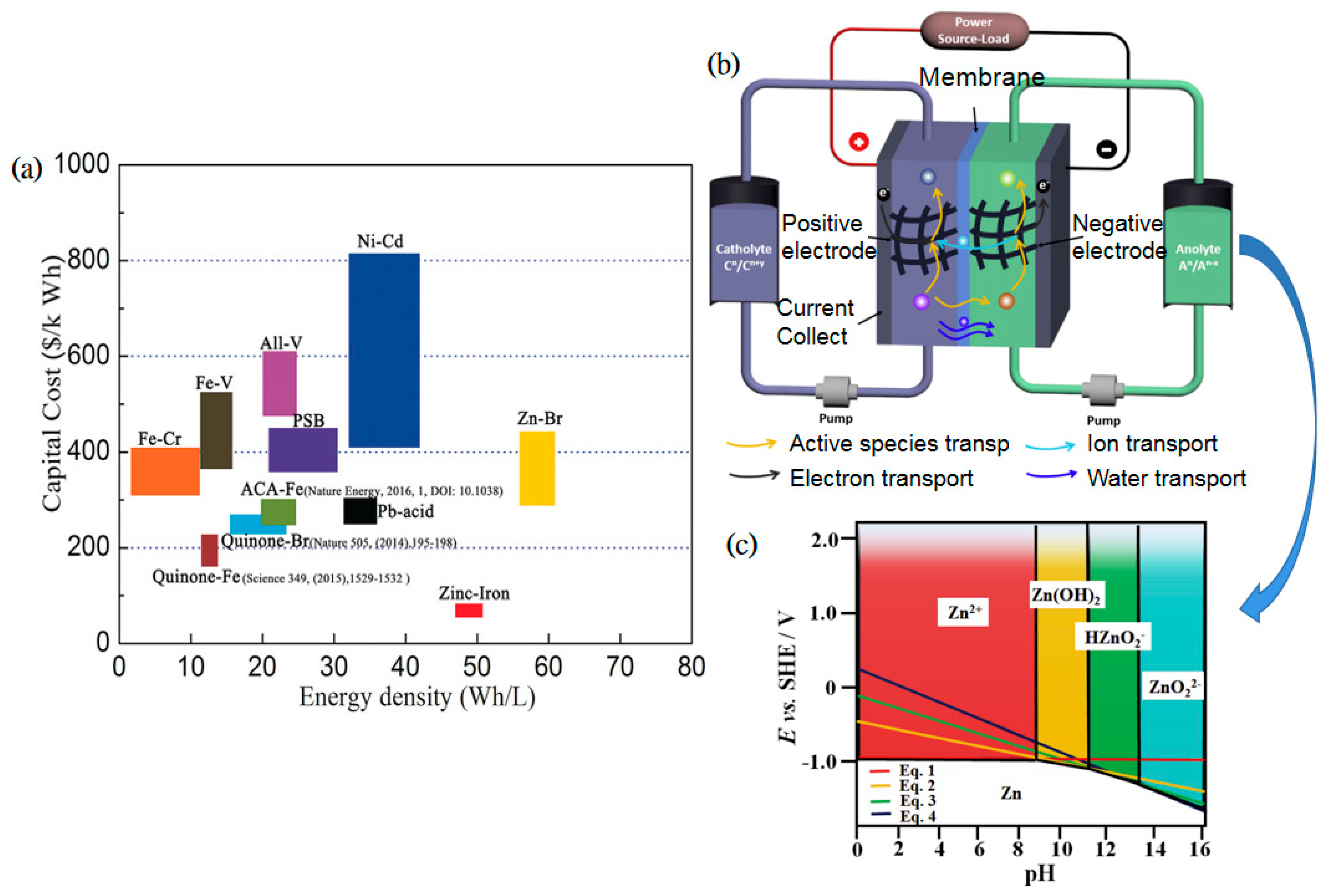
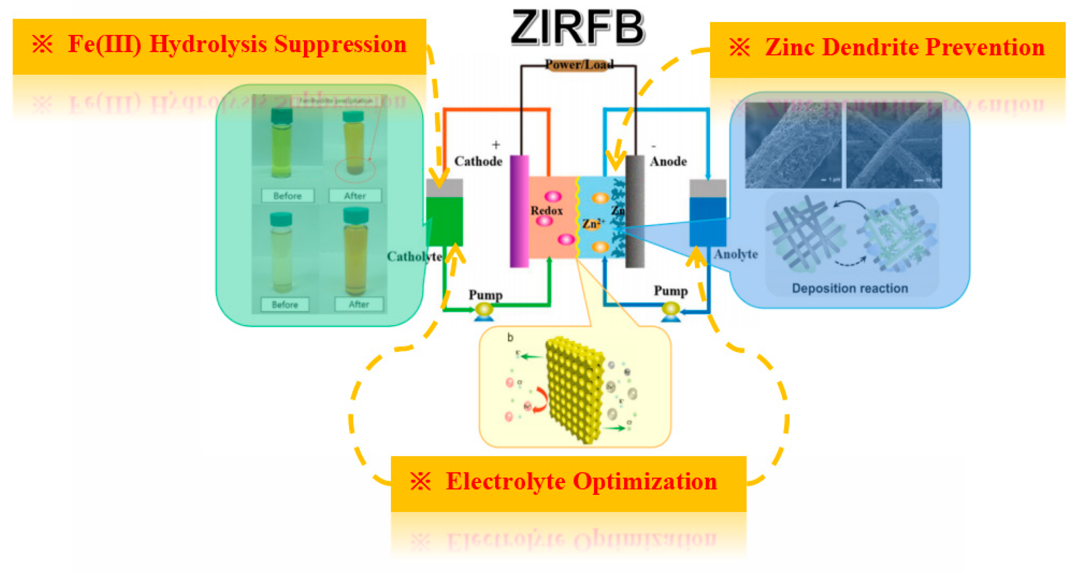
2.1. The Basic Principle of ZIRFB

ZIRFB has the general characteristics of RFBs. That is to say, the ZIRFBs mainly use the changes in the redox state of active substances in the solutions on both sides of the Fe-based cathode and Zn-based anode to realize the charge–discharge process. As can be seen in Figure 1b, a ZIRFB is mainly composed of a stack and two electrolyte storage tanks [45]. The electrolyte is stored in a storage tank outside the stack, and then is transported to the inside and outside of the stack by the pump. The redox reaction occurs at the electrodes, and the reactive species flow back to the external storage tank with the electrolyte. The cathode and anode are separated by a separator/membrane, which can optionally allow the supporting electrolyte to pass through to maintain electrolyte balance. The separator/membrane not only separates the half-cells and avoids the cross-mixing of active species, but also provides the required ionic conductivity accompanied by the electrons transfer during the charge–discharge process.
Conventional zinc–ion batteries typically fail after 500 cycles in deep discharge operation mode. The breakdown is typically caused by the anode, mainly due to the deformation of the anode related to the inhomogeneous distribution of current on the Zn electrode and the zinc dendrite caused by the concentration polarization [48,49,50]. For ZIRFBs, during cycling, the diffusion layer becomes significantly thinner, which minimizes the concentration polarization caused by electrolyte flow. The concentration polarization may dramatically restrain the growth of zinc dendrites while the battery is charging. The simultaneous flowing solutions enable the homogenous distribution of the current and eliminate the deformation of the Zn electrode as a result of the non-stratification of the solution.
For RFB systems, the working current density is a critical parameter. The higher operating current density typically enables a smaller size of the stack and reduces the system cost. The operating current density can be intimately linked to the kinetic reversibility and electrochemical activity of the redox pairs on the electrodes, and the ionic conductivity through the membrane. In terms of conventional liquid–liquid RFBs (with the whole electrochemically active components dissolved in the catholyte and anolyte during charge and discharge), most redox pairs exhibit fast kinetics and high reversibility on porous carbon electrodes, enabling these RFBs to operate under higher current densities, as shown in Table 2. Therefore, although the operating potential of conventional liquid–liquid RFB systems is typically lower than ZIRFBs, they can provide relatively higher output power in comparison with the ZIRFB system. In contrast, the ZIRFB system usually operates under a relatively low current density, owing to the limitations related to the Zn redox pair during the cycling operation.
Besides iron and zinc being the metals with the lowest cost (<USD 4 kg−1) and richest reserves in the Earth’s crust, compared to other ZBRFBs, the ferro- and ferricyanide are the most widely known iron complexes with high reversibility in alkaline solutions. The active species in the catholyte were ferri- and ferrocyanide in the form of precipitations obtained through crystallizers or when electrolytes were saturated. Despite the adoption of solid-state active species, in the 1M KOH solution, the solubility of potassium ferrocyanide can reach c.a. 0.5 M at 25 °C [67]. In the acidic ZIRFB system, the acetate buffer solution plays a vital role as it restrains the concentration of free H+ within a preferred range, which enables more proton transfers from the cathode to the anode. In addition, a higher acid concentration is preferred for the dynamics of the Fe2+/Fe3+ reactions. It is of great importance as well that carbon felt was adopted as the anode, upon which it has the disposition to be difficult for zinc deposition without the buffer solution [53]. Comparisons of the ZIRFB with other zinc-based RFBs have been further described in Table 3.

2.2. Wide pH Range

Metallic Zn can be electroplated in four various ways with different forms of reactants in the solution depending on the pH from 0 to 16, as shown in Figure 1c [18]. The relevant reaction equations are as follows:
Z n 2 + + 2 e Z n · E e = 0.763 + 0.0295 log [ Z n 2 + ]
Z n ( O H ) 2 + 2 H + + 2 e Z n + 2 H 2 O E e = 0.439 0.0591 p H
H Z n O 2 + 3 H + + 2 e Z n + 2 H 2 O E e = 0.54 V 0.0886 pH + 0.0295 log [ H Z n O 2 ]
Z n O 2 2 + 4 H + + 2 e Z n + 2 H 2 O E e = 0.441 V 0.1182 pH + 0.0295 log [ Z n O 2 2 ]
Unlike other RFBs, the electrolyte of ZIRFB can work in a wide pH range. A higher pH value is conducive to the dissolution and deposition of metallic Zn, despite that the Fe2+/Fe3+ redox couple tends to precipitate more easily at high pH. Hence, the appropriate pH range is very important. According to the difference in electrolyte acidity and alkalinity, ZIRFBs are normally divided into three types: alkaline, acidic, and neutral ZIRFBs (Table 2).

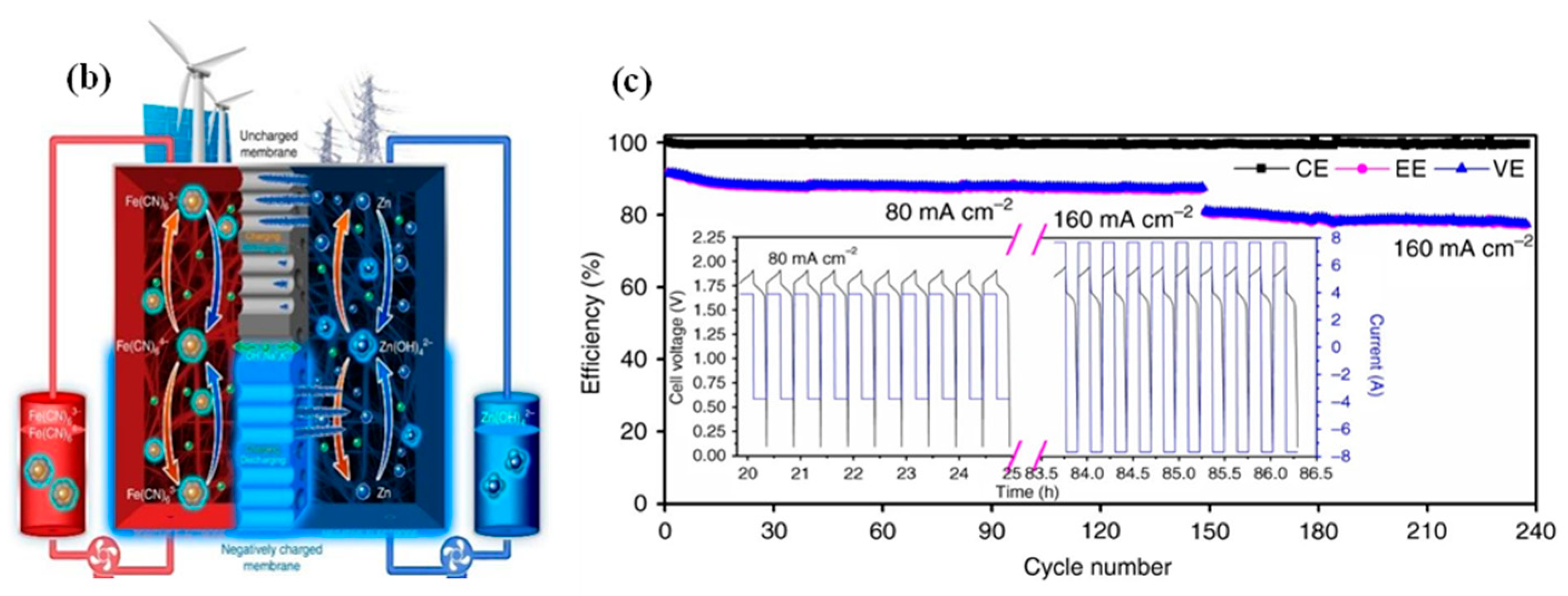
2.2.1. Alkaline ZIRFB
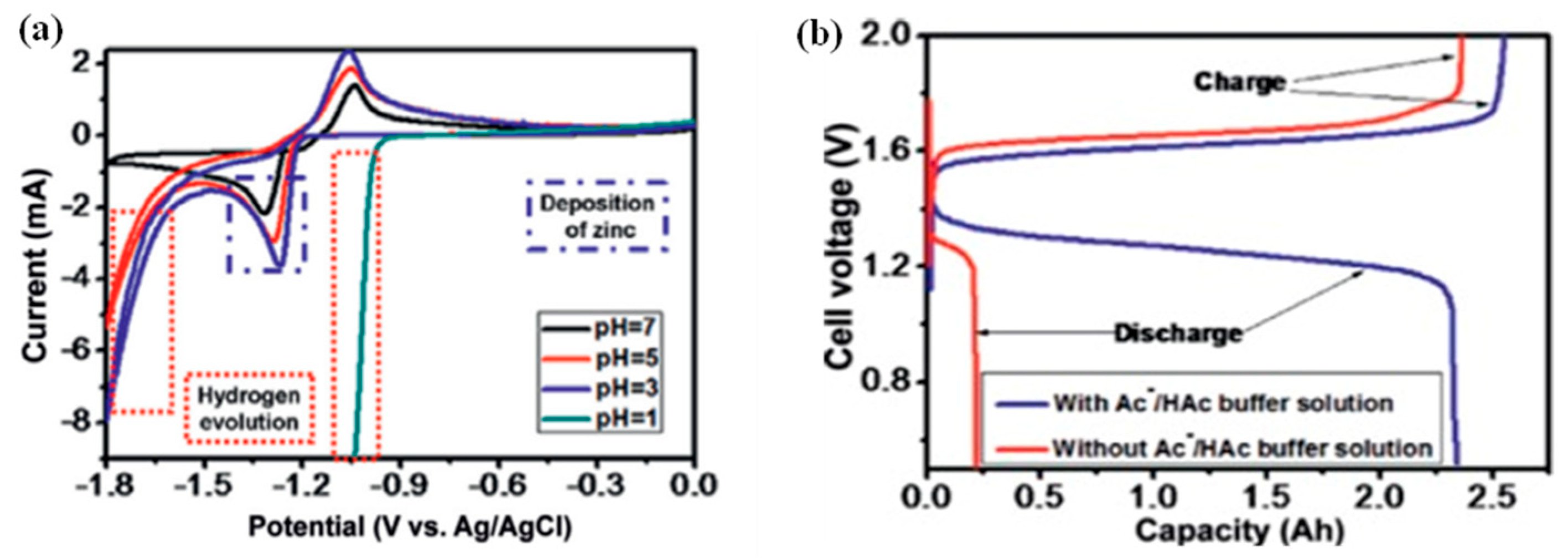
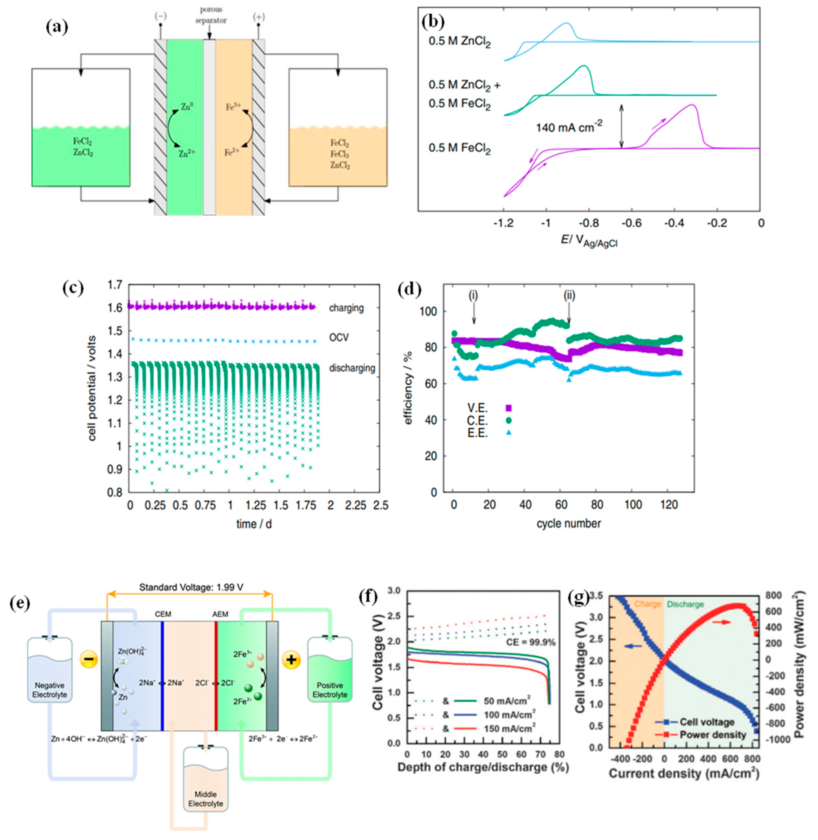
In alkaline ZIRFB, zinc and ferricyanide are used as active substances in the anolyte and catholyte, respectively [51]. The system possesses the electrolyte with relatively low cost and high open-circuit voltage (OCV) of 1.74 V. In the discharge state, the anode side is transformed from Zn to zincate solution (alkaline), while the cathode side ferrocyanide is formed from the previous ferricyanide. When charging, it is the opposite process, which is a reversible reaction compared to the discharge process. However, the cycle performance of the ZIRFB is poor due to the issue of zinc dendrites in the alkaline medium.
In 1979, G. B. Adams et al. first proposed the concept of alkaline ZIRFB in a patent [73]. The ZIRFB in this patent employs a cationic exchange membrane (CEM) to separate the active species on both sides. The CEM with high resistance makes the operating current density of the RFB low (cell resistance at 35 °C was 0.42 Ω). Additionally, another restriction of such an alkaline system is that the redox couple [Fe(CN)6]3/[Fe(CN)6]4 has very low solubility (5N). Ultimately, the alkaline ZIRFBs have not been in fast development due to the low power density and high cost of ion-exchange membranes.

2.2.2. Acidic ZIRFB

Compared with the solubility of ferricyanide in an alkaline medium, Fe2+/Fe3+ is the more ideal redox couple. Aqueous iron ions have a higher solubility and faster kinetics in an acidic medium, even on uncatalyzed carbon electrodes. Fe2+/Fe3+ is regarded as the safest and cheapest redox couple in the possible reactions for a positive electrode. Therefore, in theory, the acidic ZIRFB (Ecell = 1.53 V) can have a higher energy density [54]. However, in the acidic ZIRFB, the excessive acidity of the solution will affect the deposition of zinc and the hydrolysis of the Fe2+/Fe3+ pair, thus, the hydrogen evolution reaction (HER) is prone to occur. For an acidic system with HAc/NaAc as the buffer solution to keep the pH value of the negative electrolyte between 2–6, a high CE (coulombic/current efficiency) can be realized [53].

2.2.3. Neutral ZIRFB
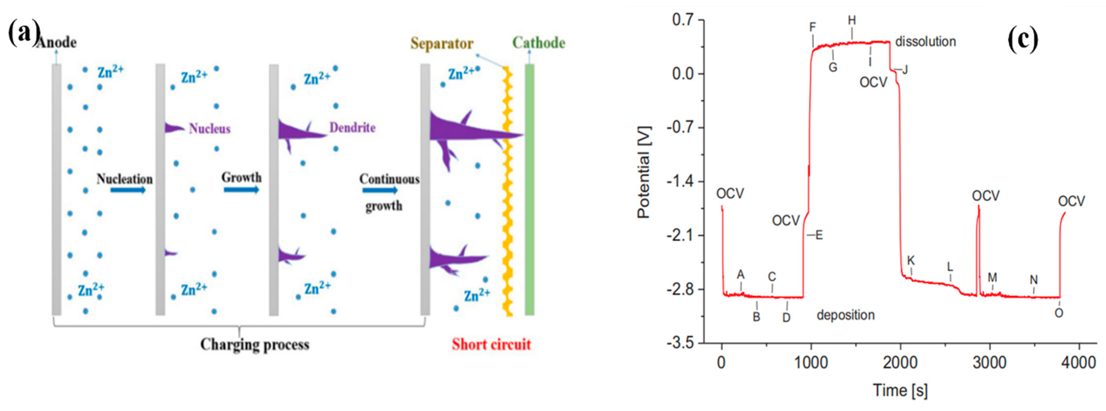
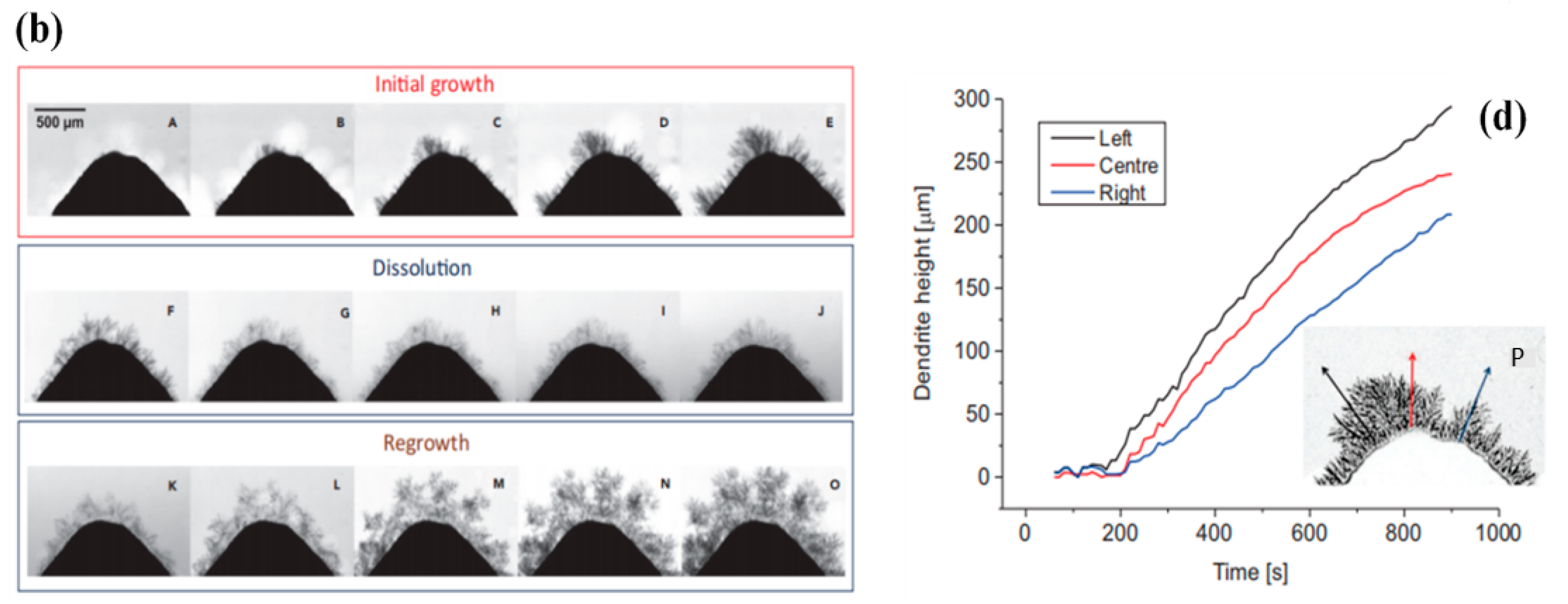
Compared with alkaline and acidic systems, the neutral ZIRFB system (Ecell = 1.43 V) is mild and non-corrosive, which has lower requirements for the membrane/separator and other components [44]. The neutral ZIRFB has a lower battery cost than the other two systems, to a certain extent. Nevertheless, regarding the neutral ZIRFB system, it also has to be taken into account that the hydrolysis of Fen+ ions may lead to the decline of battery cycle performance, which is one of the primary challenges for this type of battery.
An innovative complex system extended the range of neutral ZIRFB, which is based on a double membrane and a triple-electrolyte design [55]. The aim of the design of the double membrane was to realize the application of iron in the acidic solution and zinc in the basic solution environment at the same time. This configuration may facilitate the application of redox couples with various ion charges, together with supporting electrolytes with various pH values.

2.3. Zinc Dendrites

In comparison to other battery systems, for instance, lead-based and lithium-based batteries, the capacity/energy/power of the liquid–liquid RFBs can be designed independently [45,74,75]. In fact, the ZIRFB is a kind of “half-RFB”. In the electrode reaction, the iron-based active substance on the cathode side is always present in ionic form, while the zinc-based active substance on the anode side is under the plating–stripping process of zinc. This indicates that the power and capacity of the ZIRFBs are not devised flexibly in comparison with the liquid–liquid RFB because the capacity of the ZIRFB is restricted by the surface area of the electrode during the plating–stripping process [36].
The essential problem during the plating-stripping transversion is that the zinc dendrites mainly formed during battery charging. The existence of zinc dendrites can easily lead to problems such as a reduction in battery coulombic efficiency (CE) and capacity, and the shortening of battery life. In severe cases, it will impale the separator/membrane and lead to a battery short-circuit, as shown in Figure 2a [51,76]. In Figure 2b, the formation, dissolution, and regrowth of Zn dendrites have been made an operando investigation by the synchrotron X-ray computed tomography (SXCT) [77]. Figure 2c,d presents the corresponding chronopotentiometry data and growth curves of each dendrite at various positions of the Zn anode tip [77].
The primary reason is that Zn dendrites are more grievous when the operating current density is high. Under higher current densities, the concentration of zincate or Znn+ in the electrode interface area is extremely low, as the transfer rate of zincate or zinc ions in the electrolyte is obviously slower compared to the reaction rate on the electrode. This may bring about severe concentration polarization [36]. Furthermore, the diffusion of zincate/Znn+ tends to realize on the protrusions of the electrode compared to the flat surface, making it easier for zincate or zinc ions to undergo a plating process on the protrusions, and further results in the generation of Zn dendrites. Due to the presence of severe zinc dendrites at high operating current densities, ZIRFB usually operates at relatively lower current densities. Considering the ZIRFB system with high potential, finding an effective approach to tackle the problem of zinc dendrites, in order to enable the system to operate at higher current densities, may significantly promote such a system application. Yao et al. established the two-dimensional growth model of zinc dendrites to simulate the evolution process of zinc dendrites [78]. The numerical simulations described the zinc dendrite morphology (Figure 3a), the distribution of ion concentration (OH, Zn(OH)42) (Figure 3b,c), and electric potential (Figure 3d) at different charging times. The results provide an important reference for the inhibition of zinc dendrites in the alkaline environment. The authors also gave some approaches to control dendrites by adjusting the anisotropy intensity, increasing the electrolyte flow rate, and decreasing the current density.

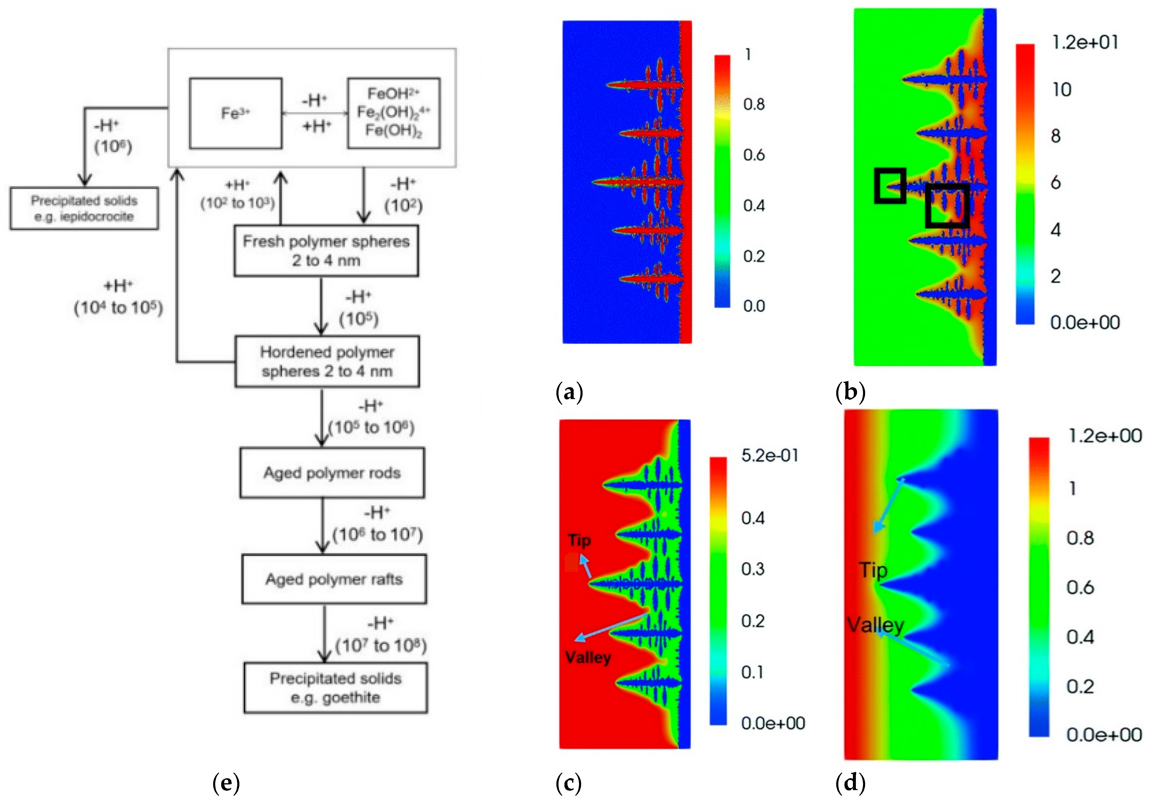
2.4. Fe(III) Hydrolysis

The hydrolytic reactions of Fe3+ are much stronger than those of Fe2+ and, consequently, hydrolysis occurs at a much lower pH. There are few reliable investigations of the hydrolytic reactions of Fe2+ because of both the low solubility and its propensity to be oxidised to Fe3+, which can greatly interfere with the ability to measure Fe2+ hydrolysis reactions. There have been several investigations that have examined the hydrolytic reactions of Fe3+, particularly that of the monomeric species, FeOH2+. It is surprising, therefore, to find that a substantial amount of conjecture remains which concerns the stability of the Fe3+ hydrolytic species and phases [80]. The hydrolysis reaction of Fe3+ can be described by Reactions (5)–(7) [80]. Similar to standard hydrolysis reactions, the interaction of Fe3+ with water takes place in several stages. Firstly, the iron cation reacts with water.
Fe3+ + HOH → FeOH2+ + H+
The resulting product will continue to bind to another water molecule.
FeOH2+ + HOH ↔ Fe(OH)2+ + H+
In the final stage,
Fe(OH)2+ + HOH ↔ Fe(OH)30 + H+
Flynn Jr. further summarized the hydrolysis processes in Fe(III) solutions at 25 °C, as shown in Figure 3e [80]. De Bruyn et al. briefly examined the hydrolysis processes in Fe(III) solutions at 90 °C [81]. The decrease in the polymer lifetime was observed with increasing temperature, so there was precipitation rather than soluble polymers conducted by titrations at 90 °C.
It should be noted that the hydrolysis of Fe3+ is reversible. Kinetics plays a vital role in iron chemistry, especially in the precipitation and dissolution of its solid phase in a water system. The hydrolysis process mainly takes place at pH > 4.5, and Fe3+ may precipitate as ferric hydroxide. Hence, the hydrolysis of iron is more likely to occur in neutral ZIRFBs. Poor coagulation may appear in the pH range between 7 and 8.5. The ferric ion hydrolyses to form hydrates and an acid. Enough alkalinity must be present to combine with the acid and maintain a suitable pH for good coagulation. Unlike Al(OH)3, ferric hydroxide does not redissolve in alkaline solutions, so there is no particular upper pH limit for ferric coagulation.

3. Research Status of Several Key Problems in ZIRFBs

According to the characteristics of ZIRFBs, the key problems need to be improved including Fe(III) hydrolysis suppression and zinc dendrite prevention, which address the electrode, membrane, and electrolyte optimization, correspondingly. The research hotspot is summarized in Figure 4, and the specific status is discussed in the following section.

3.1. Zinc Dendrite Prevention

At present, the suppression of zinc dendrites in ZIRFBs has mainly improved and optimized from the aspects of the electrode, membrane, and electrolyte.

3.1.1. The 3D Electrode

The electrode is the place where zinc deposition occurs, and the structure and physical–chemical characteristics of the electrode have a critical influence on zinc plating/stripping (Z-P/S). The three-dimensional (3D) porous carbon felts (CF) possess a high specific surface area and porosity, they can provide more sufficient spaces for Z-P/S, effectively inhibit zinc dendrites and aggregation, and ensure excellent cycle stability and rate performance [51,53]. Wang et al. claimed that a relatively lower potential delay (under 50 mV) after 350 cycles at 1 C has been achieved by adopting graphite fiber as the framework for Zn metal anodes in hybrid aqueous batteries [85]. The study from Zeng et al. demonstrated that the flexible three-dimensional carbon nanotubes (CNTs) framework built as the Z-P/S falsework may realize the robust zinc anode without dendrites [86].
Yuan et al. investigated the influences of zinc plates and CF on zinc dendrites and battery performance in alkaline ZIRFBs [51]. As shown in Figure 5a,b, the phenomena of an uneven zinc deposition and zinc dendrites are clearly observed on the zinc plate [51]. Due to a poor electronic conduction between the Zn plate and the deposited metallic Zn, some ions of Zn(OH)42− are permanently plated during the charging process. The deposited metallic Zn on the Zn plate is peeled off when the discharge process takes place, and it ultimately results in the deformation and corrosion of the Zn electrode. The zinc deposited on the CF electrode is relatively uniform in Figure 5c–h [51]. Typically, the electrode with strong adsorption ability and a high specific surface area is projected to demonstrate high enough electrochemical activity. The limited surface area will restrain the mass transfer, hence, the resistance enhances as a result of the size exclusion effect [87]. A high specific surface area from the CF electrode is not only beneficial to abate the polarization further, but also to decrease the internal interface resistance between the electrode and the deposited metallic Zn greatly. Moreover, the deposited metallic Zn on the CF electrode is also porous, which is more conducive to the diffusion of OH. Finally, under 80 mA cm−2, the EE in the kilowatt stack of ZIRFBs composed of the CF electrode can reach 84.05% (Figure 5i), which is significantly higher than that of the ZIRFB (78.52%) composed of the Zn plate as the electrode (Figure 5j) [51].
Chen et al. reported a transient 2D mathematical model to investigate the porous electrode in alkaline ZIRFBs for the first time [88]. The outcomes indicate that the thicker the electrodes and the higher the electrode porosity, the better the performance of the battery, as shown in Figure 6a,b [88]. With an asymmetric structure of a 7 mm thick anode and 10 mm thick cathode, when the electrode porosity is 98%, the EE, CE, and the utilization rate of the battery can reach 92.84%, 99.18%, and 98.62%, respectively, which are dramatically beyond that of the conventional alkaline ZIRFBs. The species distribution of the battery adopting the optimization of the porous electrode and flow rate were much more uniform than the initial design, as shown in Figure 6c,d. It provides a theoretical basis for improving the design of alkaline ZIRFBs. Beck et al. presented a 3D model of a porous electrode to generate architected electrodes, which decreased power loss more than the bulk electrodes, owing to porosity distribution optimization (see Figure 6e) [89]. The power efficiency of framework scaling up from 4 cm2 to 64 cm2 was reduced by 12.3% using the electrode with variable porosity, but by 40.3% using the electrode with uniform porosity.

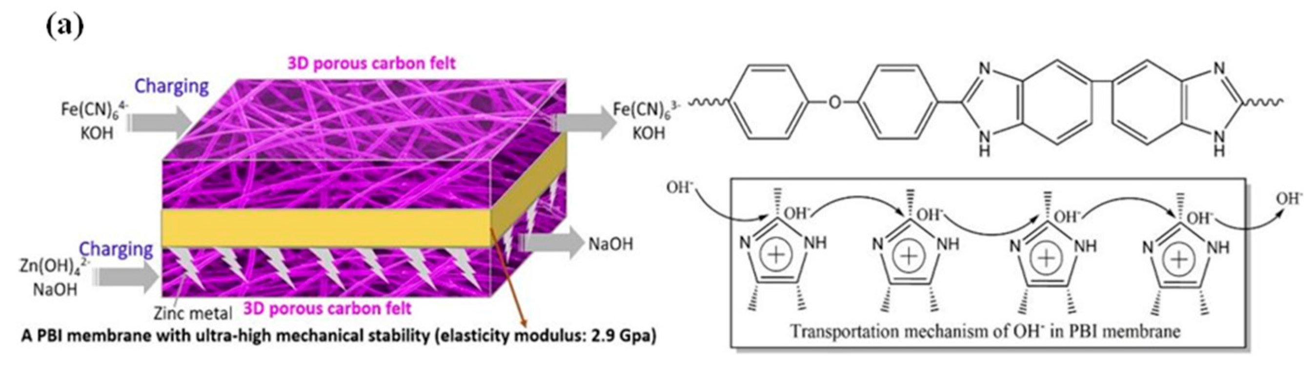
3.1.2. Improving Membrane/Separator

The membrane/separator is a critical material in RFBs as well, mainly influencing the RFB performance of the battery to a great extent, especially the CE and capacity retention. The membrane/separator divides the negative and positive half-cells to refrain from battery short circuits. Meanwhile, the membrane provides ion transportation pathways to make a conductive circuit to optionally enable H+ or specific ions to pass through, avoiding the crossover between the catholyte and anolyte. To achieve a higher battery, CE requires a higher ionic selectivity of the membrane. Hence, the ideal ion-selective membranes for RFBs should satisfy the following requirements: excellent mechanical properties, high cycle stability, good ionic conductivity and selectivity, and low active species crossover and self-discharge rate. For ZIRFBs, the only concerned metallic ions which may permeate through the membranes and lead to capacity fade are Fen+ and Zn2+. The radius of Fen+ is between 63–92 pm, which is much smaller than that of Zn2+ (139 pm). Hence, the crossover of Fen+ takes place much easier than Zn2+. It was reported that the permeability of the Fen+ ion through Nafion was 5.5 × 10⁻⁵ cm2/min, which was 18.9~20.7 times higher than that of the vanadium ion (2.9 × 10⁻⁶ cm2/min). For the modification and improvement of membranes for RFB applications, inorganic–organic hybrid membranes and polymer blending composite membranes are widely used to reduce the undesired permeation of metallic ions and improve the ion selectivity of IEMs (ion-exchange membranes) [6,75]. Originally, the Dupont Nafion membranes were extensively adopted in ZBRFBs. However, their high expense limited their large-scale applications [90]. As a result, for the sake of the promotion of ZIRFB development, scholars have devised novel membranes that are appropriate for the ZIRFB system.
The main hazard of zinc dendrites is to pierce through the membrane/separator and result in the battery short circuit. To avoid zinc dendrites from piercing the membrane/separator, membranes with high mechanical strength can be selected, such as the PBI (polybenzimidazole) membrane [51]. The PBI membrane with heterocyclic rings may ensure the rapid transportation of OH-, as shown in Figure 7a [36,51,91]. Concurrently, the PBI membrane owns strong mechanical stability and can resist zinc dendrites well, thus, ensuring the long-term cycling stability of alkaline ZIRFBs. At the same time, the use of porous ion-conducting membranes instead of traditional IEMs solves the problem of an increased internal resistance of the membrane due to iron ion pollution, and improves the conductivity of ions from the neutral medium through the membrane, which greatly improves the performance and stability of neutral ZIRFBs. More importantly, the cost-effective porous separator adopted reduced the cost of ZIRFB to below USD 50 per kWh, which is the minimum among the reported values up to now. Compared with other RFB systems, this system demonstrates good application prospects at a lower cost, and this work has important guiding significance for the research and exploitation of novel generation RFBs. The membrane can also be modified. Yuan et al. prepared a nanoporous separator that possesses negative charges in the pore surface and wall [52]. With this separator, the deposition of zincate ions is induced from the separator to the CF framework by the mutual repulsion between the pore surface/walls of the separator and the zincate ions Zn(OH)42−, as shown in Figure 7b [52]. Hence, even if Zn dendrites are formed, their growth direction is through the back of the separator, and it avoids the fracture of the separator and the short-circuit phenomenon of the ZIRFB. By employing this kind of negatively charged nanoporous membrane, there are still no zinc dendrites at 80–160 mA cm−2 for 240 cycles (Figure 7c). It has been found that the critical superiority in the ZIRFB with anion exchange membranes is that no dendrite growth has been observed on zinc electrodes during the long-term charge–discharge cycles, which was a significant drawback for the previously reported zinc-based RFBs with cation exchange membranes [92].
Just as other RFBs usually adopt non-fluorine membranes to replace expensive perfluorosulfonic acid membranes, such membrane materials can also be employed on neutral ZIRFBs [93,94]. Chang et al. designed a cost-effective potassium-form sulfonated polyether ether ketone (SPEEK-K) membrane by a solution casting method for a neutral ZIRFB, with the battery demonstrating excellent performance [95]. In detail, the prepared pristine SPEEK membrane is soaked in 1 mol L−1 KOH to obtain the SPEEK-K type membrane in potassium form, as shown in Figure 8a [95]. Under 40 mA cm−2, the EE and CE exceed 78% and 95%, respectively, which indicates that the SPEEK-K membrane may remarkably inhibit the permeation of the active substances due to repulsion effects. Therefore, the open-circuit potential (OCP) curve of the SPEEK-K membrane can last ca. 21 h at 0.5 V, and is 6 h longer than that of Nafion 117 (N117) (Figure 8b) [95]. Moreover, the discharge capacity of the ZIRFB assembled with N117 is 16.4% lower than that of the SPEEK-K membrane in Figure 8c [95]. The cost of the N117 is much higher than that of the SPEEK-based membrane by around 13-fold. Therefore, it is very competitive to employ a SPEEK-based membrane for ZIRFB applications due to the scale cost.
Besides IEMs, researchers have also attempted to employ non-ionic membranes (n-IEMs) for alkaline ZIRFBs. Chen et al. prepared a cost-effective n-IEM based on poly (ether sulfone) (PES) with high alkali resistance and chemical stability [96]. The n-IEM is prepared with bifunctional polyethene glycol (PEG) as additives and PES as the substrate. Figure 8d–f demonstrate the cross-sectional morphology of the n-IEM with different PEG contents remaining of 50 wt% (P50), 52 wt% (P52), and 55 wt% (P55), respectively [96]. Figure 8g explains the effect of PEG: (i) the alkalized-ether functional groups are beneficial to conduct charge balance ions; (ii) partially dissolving in water helps to form nano-pores in the matrix [96]. Therefore, the ZIRFB assembled with the P52 membrane in Figure 8h exhibits a CE of 99.26% and an EE of 86.81% under 80 mA cm−2 [96]. After immersing the obtained membranes in NaOH (6 mol L−1) for 8 days at 50 °C, the ZIRFB can still operate stably under 80 mA cm−2 for over 120 cycles, indicating a high alkali resistance of the obtained membranes. The results verify that the n-IEM is prospective for alkaline ZIRFBs as well.
Designing or improving the battery configuration is also used to keep the zinc dendrites away from the membrane or to avoid direct contact between the membrane and the anode. Recently, Higashi et al. designed a reverse electroplating structure, which can be used in zinc half-cells [97]. In detail, a traditional zinc metal foil electrode is used for facing the copper working electrode directly. The zinc metal foil acts as both counter and reference electrodes. During the zinc deposition in the traditional frontside-depositing configuration (Figure 9a), zinc dendrites grow along the zinc reference electrode, resulting in the short-circuit of the RFB [97]. However, in the new configuration (Figure 9b), the ‘front’ surface of the copper foil still faces the zinc metal electrode, and the backside-depositing of zinc is achieved by plating an insulating layer on the edges [97]. The small dendrites (Figure 9c) from the conventional frontside-plating configuration might osmosis slowly, but they still lead to the short-circuit due to the larger size during growing [97]. In the backside-plating configuration, during the zinc plate, zinc ions in the solution move towards the edge and are coated on the open back surface of copper foil. Thus, only polyhedral Zn deposits can be observed throughout the back surface of copper in Figure 9d, which do not lead to an electrical short due to the dendrites forming in the backside-plating configuration [97]. The short circuit caused by zinc dendrites can be avoided and the long-term cycling can be realized, which is demonstrated in Figure 9e [97]. This approach may also bring reference and guidance for future ZIRFB structure design.

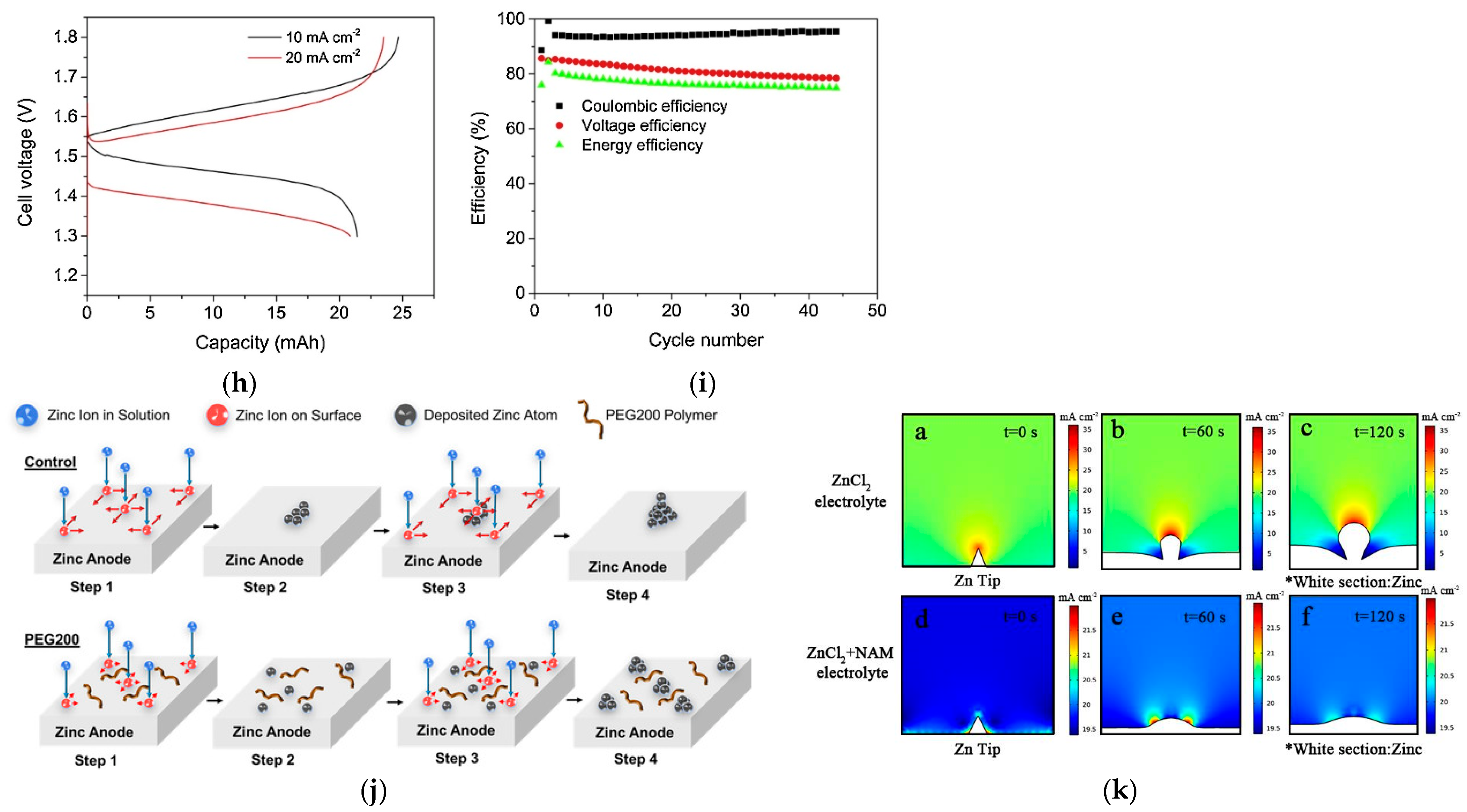
3.1.3. Adding Additives to the Electrolyte

The electrolyte is the source that affects the generation and growth of zinc dendrites. Therefore, the employment of additives into the catholyte/anolyte is a common method to suppress zinc dendrites by direct intervention in the formation of crystal nuclei. Additives can be mainly divided into three categories: metal ions, organic molecules, and polymers.
Metallic ions may influence Zn nucleation, and thus, affect the growing process. Therefore, a compact and homogeneous Zn deposit layer is obtained (e.g., SnO in Figure 10a) [98]. Zhang et al. reported that the aqueous CaCl2 solution containing NH4Cl is appropriate to be a supporting electrolyte [99]. Severe Zn dendrites are detected by SEM in 0.1 M ZnCl2 solution, as shown in Figure 10b. Meanwhile, bulk Zn metal is detected with 1 M NH4Cl as the supporting electrolytes, which is demonstrated in Figure 10c. The cyclic voltammogram (CV) curves in Figure 10d show the redox peaks sharpen obviously in the presence of NH4Cl and independent of the amounts of NH4Cl, meaning that the nucleation hysteresis decreases significantly. It can be confirmed that the addition of NH4Cl may promote Z-P/S significantly. When the CaCl2-supporting electrolyte without NH4Cl was employed, a smaller size of zinc dendrites compared to Figure 10b is reported in Figure 10e. However, no prominent Zn dendrite, but only bulk Zn with random holes, is detected in the CaCl2/H2O (3.5 m) solution with 0.5 M NH4Cl (Figure 10f). The CV curves in Figure 10g are analogous to those in aqueous NH4Cl solutions, but the redox peak currents enhance with the addition of NH4Cl. Therefore, for Z-P/S, a preferable supporting electrolyte has been an aqueous CaCl2 and NH4Cl solution. The charge–discharge curves under various current densities in Figure 10h demonstrate a clear plateau with an average voltage of 1.5 V. As shown in Figure 10i, the CE and EE reach 94% and 75% at 20 mA cm−2, respectively.
Organic molecules and polymers inhibit the Zn plating on protruding sections and promote the growth and nucleation of Zn on dents by electrostatic shielding and/or steric effects (e.g., polyethylene glycol, PEG in Figure 10j) [100]. The numerical simulations of neutral ZnCl2 anolyte, in Figure 10k, further verified an electrostatic shield to regulate the electric field by employing nicotinamide (NAM) as a cost-effective additive, which was proposed by Yang et al. [35].

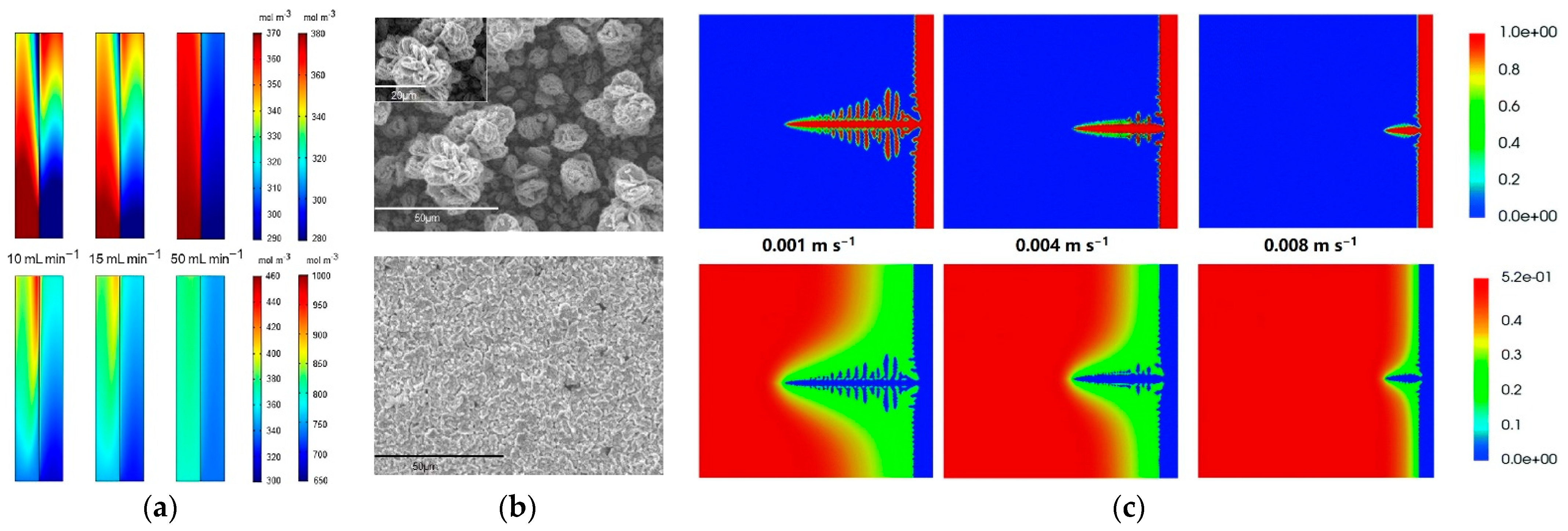
3.1.4. Flow Field Regulation

The electrolyte flow acts a vital role in Zn dendrites, not only owing to changing the gradient distribution of zinc ions, but also reshaping the orientation of dendritic growth. When electrolyte flow velocity is 50 mL min−1, as shown in Figure 11a, the species concentration distribution is uniformly obtained by numerical simulation [87]. Additionally, in Figure 11b, it is very clear that two different zinc-depositing morphologies can be observed under the conditions of the quiescent electrolyte and the flowing electrolyte [101]. A higher flow rate of the electrolyte may enhance the transport velocity of Zn2+ which accelerates the diffusion process on the electrode accessory surface and the mass-transfer process in the bulk electrolyte, thus, finally reducing the Zn2+ concentration gradients and constraining the formation and growth of dendrites. Furthermore, a relatively high flow rate results in mitigating dendritic growth, as the formed dendrites are washed away directly by the electrolyte [17]. Figure 11c shows the simulation results, which displays zinc dendrite morphology and the concentration of Zn(OH)42- ions at different electrolyte flow rates at a certain charging time. The higher the electrolyte flow rate is, the greater the dendrite inhibition will be [78]. Nevertheless, the higher flow rate may reduce the power and energy efficiency of the battery because the reaction of active species is inadequate.
It has been reported that compared to a conventional flow-by mode, the combination of flow-by and flow-through fields leads to significantly higher CE and EE, since part of the flow going through the porous electrode reduced the ohm loss and promoted the effective surface area. Such a design with a component of flow in the direction of the current feeder can enhance the flow distribution in hybrid flow batteries and restrain the blockage of the mass/ion transport pathway. In addition, it can also reduce potential loss and overpotential. Dendrite formation is likely mitigated by the promoted mass transfer, which could enable operations at higher current densities without the operational issues that may take place with traditional flow-by designs [102].

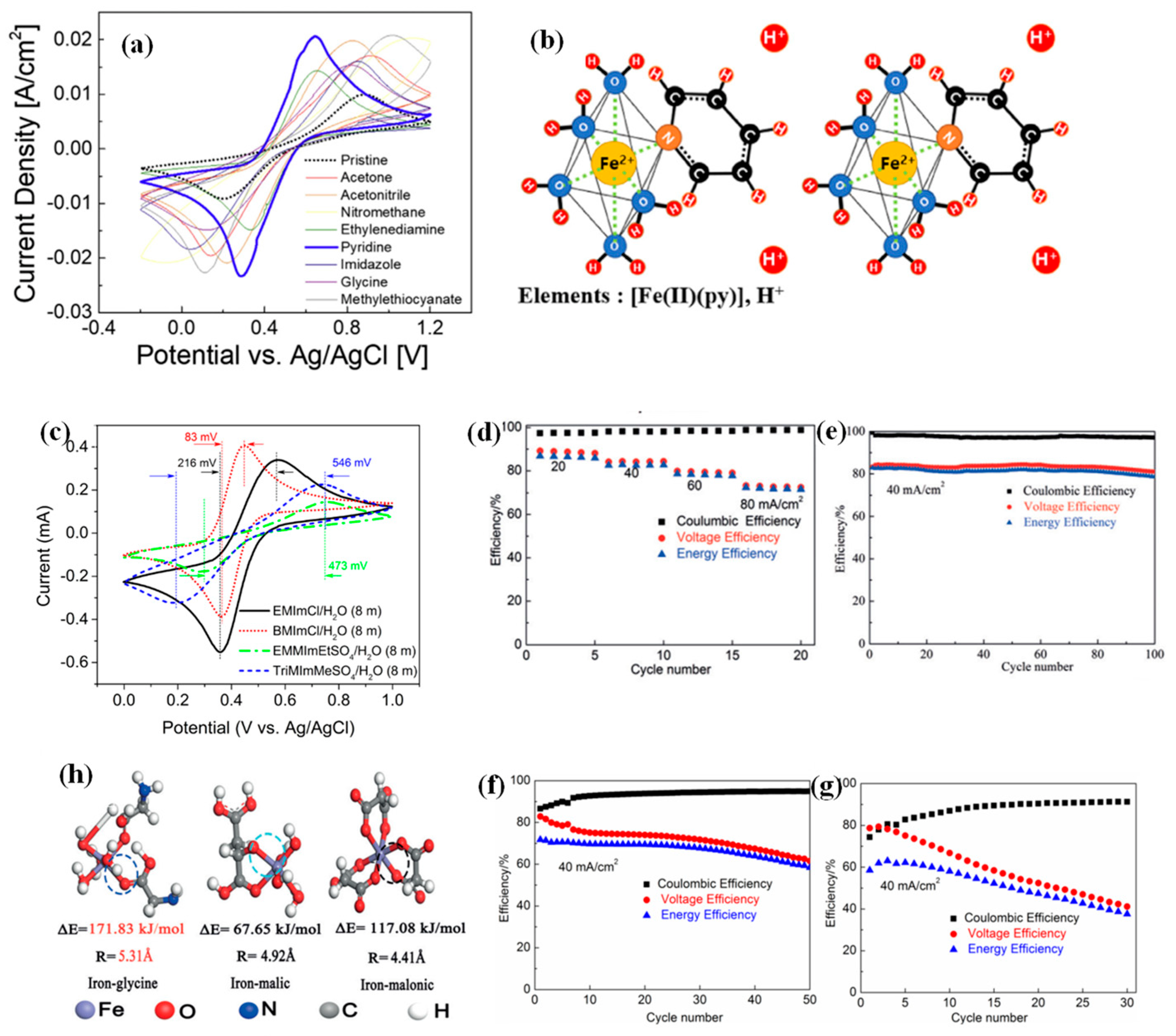
3.2. Fe(III) Hydrolysis Suppression

Both Fe2+ and Fe3+ have hydrolytic reactions in an aqueous solution. It has been reported that the hydrolysis product of iron ions will combine with the sulfonic group in the membrane to increase membrane resistance [103]. The hydrolytic reactions of Fe3+ are much stronger than those of Fe2+ and, consequently, occur at a much lower pH [104]. However, the hydrolysis of Fe3+ is easier to be suppressed in a hydrochloric acid environment [99,105].
In the catholyte of acidic ZIRFBs, polymerization takes place more seriously during the Fe2+ oxidation reaction, and ferrihydrite precipitation takes place during the Fe3+ hydrolysis process. The polymerization and hydrolysis reactions are rapidly promoted by enhancing H+/OH ions formed due to water electrolysis. To address this issue, seven types of Fe2+-complexing ligands are tested and reported, but some issues remain if we consider the binding stability and electrochemical performance of the Fe2+-ligand complex [82]. It can be concluded that a novel Fe2+-pyridine complexation in the catholyte has been presented for acidic ZIRFBs with a long cycle life and high performance over other Fe2+-complexing ligands. In comparison to other complexing ligands, the Fe2+-complexation with pyridine presents the highest electrochemical activity and reversibility, as shown in Figure 12a [82]. The pyridine initially coordinated to Fe2+ generates a much stronger bond, even though the pH is below 2 (molar ratio: Mpy = MFe, Figure 12b), and it results in the best electrochemical performances, including enhanced electron transfer and reaction kinetics [82]. For the first cycle, ‘the pyridine’ displayed a slight discharge capacity decay (only 2.9%) as a complexing ligand agent, in comparison with ‘the pristine’, which showed an enormous loss of 89.4% as a result of ferrihydrite precipitation. These outcomings demonstrate that the pyridine can not only restrain ferrihydrite during long-term cycling, but also promote the reversibility and electrochemical stability of the Fe2+/Fe3+ redox pairs.
Zhang et al. used 1-butyl-3-methylimidazolium chloride (BMImCl) to adjust the redox activity of Fen+ in acidic ZIRFBs [99]. The redox behavior of the Fe species is obviously enhanced in BMImCl solutions compared with other ionic solutions, as demonstrated in Figure 12c [99]. The diffusion coefficients of Fe3+ (DFe3+) and Fe2+ (DFe2+) are calculated after the background currents subtraction in Table 4, respectively [106]. The results show that diffusion in BMImCl is slightly easier than in the other ligands.
Three kinds of additives with various chain lengths in neutral ZIRFBs were investigated to validate the mechanism of coordination with the iron ions, that is glycine, malic acid and malonic acid. The battery’s performance with the additive is shown in Figure 12d–g [44]. Compared with malic acid and malonic acid, the battery with glycine showed higher CE, voltage efficiency (VE), and longer performance stability. The reasons have been shown in Figure 12h [44]. The optimization strategy is based on the iron-based species form complexes with higher bonding energy, which can improve the solubility and suppress the iron hydrolysis. In detail, the bonding energy of iron–glycine is much higher than iron–malonic and iron–malic acid, which indicates that glycine as the complexing agent can inhibit iron ionic hydrolysis more efficiently. Moreover, the radius of iron–glycine is also much larger than that of the above complexes, revealing that adopting glycine can realize a higher CE and a much lower permeation rate [44].

3.3. Electrolyte Optimization

3.3.1. Concentration and Additives

By optimizing the composition of the electrolyte, Yuan et al. made the concentration of the Fe(CN)63−/Fe(CN)64− redox couples achieve 1 mol L−1, far exceeding the previously reported concentration (0.4 mol L−1) [51]. The high concentration of active redox couples enables the system with a high-energy density. The battery can realize 500 cycles of charge–discharge cycling under 80 and 160 mA cm−2, and still maintain an EE over 80% and CE over 99% at 160 mA cm−2. The above-mentioned results verified the outstanding stability of this system. Most important of all, the functionality of this work is further verified by assembling a kW battery stack at a capital cost of less than USD 90 per kWh.
In alkaline ZIRFBs, the electrolytes act a vital role in resolving the reliability and EE of the system. The migration of water through the membrane is a vital parameter affecting the ZIRFB performance. It has been confirmed by Liu et al. that the cause of water transfer in alkaline ZIRFB is the synergistic effect of the electric field, various ionic strengths of anolyte and catholyte, and concentration gradient [83]. To tackle the problem of water transfer, a series of additives were tested and studied. The results demonstrate that all the additives studied can inhibit water transfer, as the ionic strength gap and osmotic pressure between the anolyte and catholyte are reduced. In addition, due to the increase in electrode polarizability, organic additives (glucose) will reduce the battery performance, while inorganic additives (Na2SO4) have no significant effect on the battery performance. In detail, an alkaline ZIRFB adopting Na2SO4 as an additive in the anolyte demonstrates a CE of ~99% and VE of ~88% during 120 cycles at 80 mA cm−2, as well as excellent effects of inhibiting the water transfer phenomenon.
ZIRFBs also suffered from water migration. During the redox reaction process, significant differences in ionic strength and concentration gradient for the catholyte and anolyte may occur, thus, making the RFB suffer from water migration and then reducing its reliability and performance of the RFB. Therefore, strategies such as optimizing the ingredient of electrolytes or adding additives to anolyte to balance/reduce the differences in electrolytes have been valid methods to alleviate the problem of water migration [46,83].

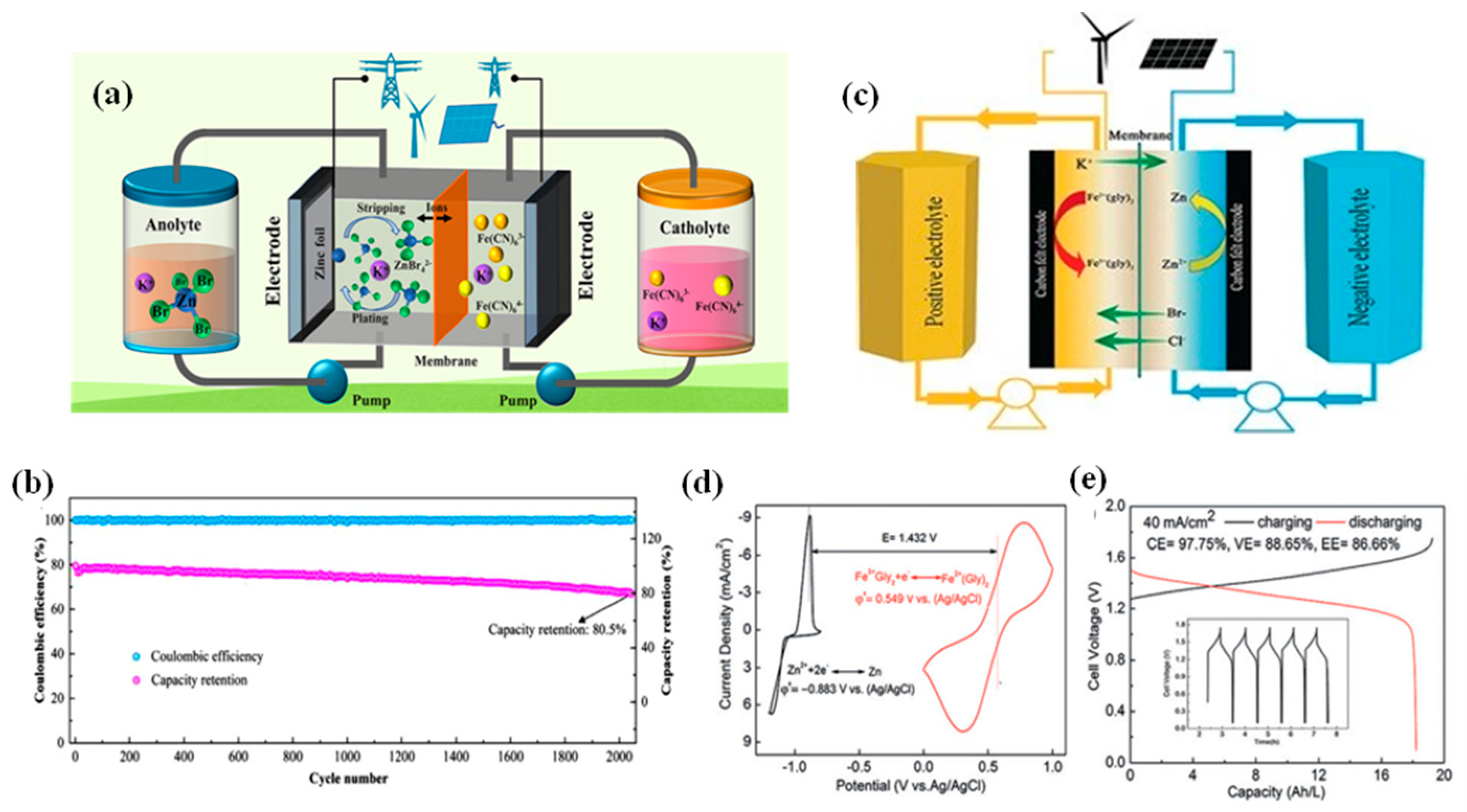
3.3.2. Zinc–Bromide Complexation

To ensure the long-term operation stability of neutral ZIRFBs, Yang et al. proposed the use of Br- ions to stabilize Zn2+ through complexation interactions in the neutral electrolytes (Figure 13a) [56]. The results of cyclic voltammetry indicate that the redox reversibility has been significantly enhanced between Zn2+ and Zn. To tackle the issue of the sluggish kinetics of the coordination interaction between Br and Zn2+, ZnBr2 as the electrolyte additive was directly selected to boost the process of complexation. By employing active K3Fe(CN)6 in the catholyte and modified species in the anolyte, the proposed neutral ZIRFB demonstrates excellent efficiencies and cycle stability (without obvious capacity decay) during 2000 cycles (356 h) (Figure 13b) [56].
Adopting FeCl2/ZnBr2 as the redox couple in the catholyte and anolyte, Xie et al. introduced glycine as a chelating agent in the catholyte (Figure 13c,d) [44]. Between 20 and 80 mA cm−2, zinc plating does not tend to be homogeneous, and the morphology gradually turns to non-uniform. However, no severe formation of Zn dendrites is observed even under a high current density (80 mA cm−2). At 40 mA cm−2, the EE can reach 86.66% (Figure 13e) [44]. The concentration of active species in the system can reach 2 mol L−1, and its volume energy density can reach 56 Wh L−1.

3.3.3. pH

For ZIRFBs, plate electrodes or porous CFs are generally adopted for Z-P/S. During charging, zinc ions or zincate ions are continuously converted to zinc metal, and then, finally, are completely plated on the electrode. Once the deposition is finished on the electrode completely, no further electroplating will be carried out. Further charging will lead to a sharp increase in the charge potential, thus, resulting in the irreversible HER in the negative half-cell.
Xie et al. reported an acidic ZIRFB, which employs Fe2+/Fe3+ and Zn/Zn2+ as the redox couples of the catholyte and anolyte [53]. In particular, the HAc/NaAc buffer solution and H2SO4 are used as the supporting electrolyte for the anolyte and catholyte, respectively. The CV curves in Figure 14a present the HER can be markedly restrained by keeping the pH of ZnSO4 solution in the range of 2–7. However, the acid medium is beneficial for the kinetics of the cathode electrode reaction and the ferric ion hydrolysis suppression. When HAc/NaAc is present in the anolyte, the pH can be maintained between 2.0 and 6.0, and a large amount of H+ ions enter the anolyte through the IEM from the catholyte. Within this pH range, the HER on the anode can be effectively inhibited and significant discharge capacity promotion can be observed for the ZIRFB with the buffer solution, as shown in Figure 14b [53]. Meanwhile, the HAc/NaAc buffer solution is also considered to be the reason to explain why no zinc dendrite phenomenon was observed. The ZIRFB achieves 50 charge-discharge cycles and maintains an EE of 71.1% under 30 mA cm−2. Under the above conditions, the battery also runs for 202 cycles, but with a severe decrease in capacity. The reason can be attributed to the cross-contamination of Zn/Fe ions passing through the IEM during repeated charge–discharge cycles, which also resulted in the loss of CE.
The HER results from the corrosion of Zn in alkaline solutions. The corrosion of Zn is the main cause of the self-discharge of secondary alkaline Zn-based batteries. The corrosion reactions are: [107]
Zn + OH − 2e → ZnO+ + H2O φo = −1.245 V
H2O + 2e ↔ 2OH + H2 ↑ φo = −0.828 V
Liu et al. investigated the effect of several inorganic and organic additives on water migration in alkaline ZIRFBs [83]. Although all these additives are proved to be effective to suppress water migration, the organic additive, such as xylitol, sorbitol, and mannitol with several hydroxyl groups, can increase the alkalinity of the electrolyte, which in turn, accelerates the corrosion rate of zinc metal and further aggravates the HER of the battery.

3.3.4. Mix System

Fe–Cr RFB in the mixed electrolyte was first invented to tackle the cross-contamination issue [13]. Hybrid RFBs, such as Zn–Fe, all-Fe, Sn–Fe, have been widely explored in order to get rid of the bondage of high-cost membrane materials. Zhou et al. reported an Sn–Fe RFB, employed SnCl2 and FeCl2 as both an anolyte and catholyte, and delivered 78.5% of EE and 0.96‰ per cycle of the capacity decay rate at 200 mA cm−2 [108]. At present, a long lifetime and a high-power density of Zn–Fe RFBs are achieved through additional operation and structural design.
Selverston et al. investigated the use of mixed electrolytes in a weakly acidic electrolyte for ZIRFBs. The feasibility of ZIRFBs with mixed-mode (Zn/Zn2+, Fe2+/Fe3+) is shown in Figure 15a [54]. The lower system cost is not only contributed by the porous separators, but the lower conductivity is also led by the iron ions conversion in lightly acidic iron chloride solutions. The presence of zinc ions has no significant effect on the electrochemical reaction of Fe2+/Fe3+ on the positive side. Under limited conditions, the zinc plating–stripping process on the negative electrode is similar to that of a normal zinc electrode (Figure 15b) [38]. The authors declared that the reason for the anomalous co-deposition on the negative side is the formation of a Zn/Fe solid solution. They further investigated the iron deposition/dissolution behavior by the Zn/Fe molar ratio, zinc mass transfer, and effects of pH in the cyclic voltammetry curves. They concluded that the anomalous phenomenon occurs only at lower Zn/Fe molar ratios and mass rates, while pH values (pH = 1, 3) have no obvious influence on the experimental results. The flow battery has been operated continuously for 10 days and 127 cycles, and the showed OCP of the first two days is maintained at 1.5 V (Figure 15c,d) [54]. There were also some necessary measures to maintain the stability of the mixed-electrolyte battery system, such as increasing the negative pressure to balance the electrolyte between positive and negative (Figure 15d(i)), and adding the electrolytes to the iron complex (Figure 15d(ii)).
Another mixed electrolyte system has been presented by Gong et al., as shown in Figure 15e [55]. They designed a new type of acid–alkaline combined ZIRFB, in which the two redox pairs of Zn(OH)42+/Zn in NaOH solution and Fe3+/Fe2+ in HCl solution can simultaneously satisfy a low electrolyte cost and a high effective discharge cell voltage. The key to achieving both acid and base in one ZIRFB is replacing a traditional single-separator with a double-separator battery structure, which adds another neutral electrolyte chamber as the buffer solution. The serious challenges mainly come from cell resistance, such as ohmic resistance and concentration-polarization resistance. Optimization measures are mainly taken by the electrolyte, for example, the ions of Na+ and Cl- with smaller diffusion coefficients, and the middle electrolyte with a thinner thickness. Finally, this type of ZIRFB demonstrated an extremely high CE of 99.9%, regardless of current densities, thus, showing an excellent separation of two redox couples as a result of the double-membrane cell configuration (Figure 15f) [55]. The power density of the battery can reach 676 mW cm−2 at 70% of the state of charge (SOC) (Figure 15g), and the investment cost is less than USD 100 per kWh, which is far below the 2023 target (USD 150 per kWh) set by the U.S. Department of Energy, thus, providing a great opportunity for the development of ZIRFBs [55].

4. Conclusions and Outlook

To make electricity-storage systems economically viable, the US Department of Energy has set a system capital cost target of USD 150 per kW h by 2023. The most developed VRFBs currently have a system capital cost around ∼USD 300–USD 800 per kW h. ZIRFBs not only demonstrate a high-power density (e.g., 676 mW cm−2), but they also offer a potential system capital cost of less than USD 100 per kWh, which highlights the significance of investigating such systems [55]. Therefore, the ZIRFB possesses the superiorities of low electrolyte cost, intrinsic safety, and wide pH range, which has become one of the important directions of new RFB technology.
In recent years, ZIRFBs have been improved by zinc dendrite prevention, Fe(III) hydrolysis suppression, and electrolyte optimization, as summarized in Table 5 and Figure 16. It is not difficult to see that while improving battery performance, various improvement methods still have certain shortcomings, especially in terms of long-term durability and the current density range of batteries, which still face many challenges. Hence, the issues of ZIRFBs have not been solved completely to meet the commercialization. In-depth research, because of the primary issues, is still needed to further understand the influencing factors and seek appropriate solutions:
(i)
The zinc dendrites are still the core challenges of ZIRFBs, especially in alkaline ZIRFBs, since they may lead to the short-circuit and reduction in the battery lifetime. The advanced materials (electrolytes, electrodes, and membranes) and interface reactions are still expected to change the growth mode of zinc dendrites from the root. The volume or space of the anode often faces to the zinc dendrites directly. Therefore, considering how to use the available space or volume to achieve the homogeneous and thicker Zn deposition layer on the surface of the electrode can be vital for the prevention of zinc dendrites. In addition, it is necessary to further clarify the electrochemical behaviors deposited on the various electrodes in multiple electrolytes to supply technical support for the realization of a dense and homogeneous zinc layer. This is also alleviated through the optimization of battery structure and other key materials.
(ii)
The membrane material is one of the effective means to improve the performance of ZIRFB. The design and manufacture of high-performance membranes are the top priority. The perfluorinated CEM is, presently, the most widely adopted membrane in the RFB system (suitable for acidic RFBs). However, ZIRFB systems are usually in alkaline and neutral mediums, since zinc metal is unstable in acidic solutions. While anion exchange membranes will degrade in an alkaline medium, dense membranes demonstrate a relatively high surface resistance in the neutral medium as well. Porous membranes are considered to be one of the best choices at present. Furthermore, the generation and accumulation of zinc dendrites may pierce the membrane and lead to a short circuit. Therefore, the research and development of membrane materials with good mechanical properties, especially puncture-resistant and self-recovery capabilities, is a top priority. Innovative polymers, through molecular design, are still essential to make membranes with high performance for ZIRFB applications.
(iii)
The optimization of the supporting electrolyte and complexing agent is still the key to solving the problem of ferric iron hydrolysis. In this process, the influence of electrolyte source cannot be ignored. The supply of raw materials mainly comes from iron ore and copper ore. It should be noted that iron and copper may be associated with some special minerals, therefore, this kind of mineral is an ideal source of raw material supply for ZIRFB. Furthermore, in situ characterization techniques need to be used to investigate the evolution of catalysts and electrode reaction kinetics during electrocatalytic redox processes. The acid ZIRFB system may be a way to solve iron hydrolysis, but the current density of the acid system is very low, which is difficult to adapt to the application scenario of large-scale energy storage and the future development needs of RFB.
(iv)
Electrolyte optimization is combined with simulation and battery structure. It is important to play the role of simulation in the theoretical prediction of the characteristics and performance of more ZIRFBs, which would boost the compatibility between the component and battery. Designing/developing physical models that are in line with reality have a guiding role in the design and operation of reliable battery systems. It is notable that the optimization also needs to take the cell design and battery operation into consideration to ensure device reliability. Meanwhile, the research process about ZIRFBs should pay attention to environmental protection and the comprehensive cost.
(v)
Cost-effective ZIRFBs still realize cost reductions by focusing primarily on the ion exchange membrane. The price of non-fluorinated separators will undoubtedly be significantly lower than that of perfluorosulfonic acid membranes; in addition, the puncture-resistant separator reduces the possibility of short circuits and avoids frequent separator replacement by increasing the durability of the separator, which will also help the cost reduction in the ZIRFB system.
Recently, a research group led by Prof. Li Xianfeng from the Dalian Institute of Chemical Physics of the Chinese Academy of Sciences (CAS) developed a 10 kW alkaline ZIRFB system for field demonstrations. Additionally, it was installed and operated in the plant of Baodi Goldsun Co., Ltd. in Yantai, Shandong province, China (106). The system is matched with 13 kilowatts of photovoltaics to form an intelligent micro-grid, which adopts a combined mode of on-grid and off-grid to achieve peak power consumption, new energy consumption, and uninterrupted power supply for important loads. The field-tested demonstration system achieved an EE of 78.7%. The successful operation of the ZIRFB demonstration system lays the foundation for its future engineering and industrial development. We believe that strengthening in engineering development of ZIRFBs will accelerate the transformation of technological achievements to MW, and even, GW.

Abbreviations

RFBsredox flow batteries
ZIRFBszinc–iron redox flow batteries
ZBRFBzinc-based RFB
VRFBvanadium RFB
R.T.room temperature
OCVopen-circuit voltage
OCPopen-circuit potential
CEMcationic exchange membrane
IEMion exchange membrane
n-IEMsnon-ionic membranes
PESpoly (ether sulfone)
PEGpolyethene glycol
SPEEK-Ksulfonated polyether ether ketone
PBIpolybenzimidazole
BMImCl1-butyl-3-methylimidazolium chloride
CFcarbon felts
Z-P/Szinc plating/stripping
CVcyclic voltammogram
EEenergy efficiency
CEcurrent efficiency
VEvoltage efficiency
HERhydrogen evolution reaction
SOCstate of charge
MCmicroporous carbon
THEEDN, N, N′ N′-Tetra(2- hydroxyethyl) ethylenediamine

Author Contributions

Conceptualization, C.S. and H.Z.; formal analysis, C.S. and H.Z.; resources, C.S.; data curation, H.Z.; writing—original draft preparation, C.S. and H.Z.; writing—review and editing, M.G.; visualization, H.Z.; supervision, H.Z. and M.G.; project administration, H.Z.; funding acquisition, H.Z. All authors have read and agreed to the published version of the manuscript.

Funding

This work was financially supported and funded by the Doctoral Start-up Foundation of Liaoning Province (No. 2021-BS-242), the Excellent Talent Training Program of the University of Science and Technology Liaoning (No. 2019RC04).

Institutional Review Board Statement

Not applicable.

Informed Consent Statement

Not applicable.

Data Availability Statement

Not applicable.

Conflicts of Interest

Authors declare no conflicts of interest.

References

  1. Pagliaro, M. Renewable Energy Systems: Enhanced Resilience, Lower Costs. Energy Technol. 2019, 7, 1900791. [Google Scholar] [CrossRef]
  2. Ahmadi, M.H.; Ghazvini, M.; Alhuyi Nazari, M.; Ahmadi, M.A.; Pourfayaz, F.; Lorenzini, G.; Ming, T. Renewable energy harvesting with the application of nanotechnology: A review. Int. J. Energy Res. 2019, 43, 1387–1410. [Google Scholar] [CrossRef]
  3. Pagliaro, M.; Meneguzzo, F. Distributed Generation from Renewable Energy Sources: Ending Energy Poverty across the World. Energy Technol. 2020, 8, 2000126. [Google Scholar] [CrossRef]
  4. Fernandez-Marchante, C.M.; Millán, M.; Medina-Santos, J.I.; Lobato, J. Environmental and Preliminary Cost Assessments of Redox Flow Batteries for Renewable Energy Storage. Energy Technol. 2020, 8, 1900914. [Google Scholar] [CrossRef]
  5. Zhang, C.; Wei, Y.-L.; Cao, P.-F.; Lin, M.-C. Energy storage system: Current studies on batteries and power condition system. Renew. Sustain. Energy Rev. 2018, 82, 3091–3106. [Google Scholar] [CrossRef]
  6. Sun, C.; Negro, E.; Vezzù, K.; Pagot, G.; Cavinato, G.; Nale, A.; Herve Bang, Y.; Di Noto, V. Hybrid inorganic-organic proton-conducting membranes based on SPEEK doped with WO3 nanoparticles for application in vanadium redox flow batteries. Electrochim. Acta 2019, 309, 311–325. [Google Scholar] [CrossRef]
  7. Pal, D.; Chakraborty, S.; Chattopadhyay, S. Recent Progress in Al-, K-, and Zn-Ion Batteries: Experimental and Theoretical Viewpoints. Energy Technol. 2021, 9, 2100382. [Google Scholar] [CrossRef]
  8. Hu, Y.; Sun, D.; Luo, B.; Wang, L. Recent Progress and Future Trends of Aluminum Batteries. Energy Technol. 2019, 7, 86–106. [Google Scholar] [CrossRef] [Green Version]
  9. Zhang, H.; Sun, C. Cost-effective iron-based aqueous redox flow batteries for large-scale energy storage application: A review. J. Power Sources 2021, 493, 229445. [Google Scholar] [CrossRef]
  10. Horowitz, Y.; Schmidt, C.; Yoon, D.-H.; Riegger, L.M.; Katzenmeier, L.; Bosch, G.M.; Noked, M.; Ein-Eli, Y.; Janek, J.; Zeier, W.G.; et al. Between Liquid and All Solid: A Prospect on Electrolyte Future in Lithium-Ion Batteries for Electric Vehicles. Energy Technol. 2020, 8, 2000580. [Google Scholar] [CrossRef]
  11. Zhang, H.; Lu, W.; Li, X. Progress and Perspectives of Flow Battery Technologies. Electrochem. Energy Rev. 2019, 2, 492–506. [Google Scholar] [CrossRef]
  12. Ye, J.; Xia, L.; Wu, C.; Ding, M.; Jia, C.; Wang, Q. Redox targeting-based flow batteries. J. Phys. D Appl. Phys. 2019, 52, 443001. [Google Scholar] [CrossRef]
  13. Sun, C.; Zhang, H. Review of the Development of First-Generation Redox Flow Batteries: Iron-Chromium System. ChemSusChem 2021, 15, e202101798. [Google Scholar] [CrossRef] [PubMed]
  14. Esan, O.C.; Shi, X.; Pan, Z.; Huo, X.; An, L.; Zhao, T.S. Modeling and Simulation of Flow Batteries. Adv. Energy Mater. 2020, 10, 2000758. [Google Scholar] [CrossRef]
  15. Kim, K.J.; Park, M.-S.S.; Kim, Y.-J.J.; Kim, J.H.; Dou, S.X.; Skyllas-Kazacos, M. A technology review of electrodes and reaction mechanisms in vanadium redox flow batteries. J. Mater. Chem. A 2015, 3, 16913–16933. [Google Scholar] [CrossRef]
  16. Arenas, L.F.; Loh, A.; Trudgeon, D.P.; Li, X.; de León, C.P.; Walsh, F.C. The characteristics and performance of hybrid redox flow batteries with zinc negative electrodes for energy storage. Renew. Sustain. Energy Rev. 2018, 90, 992–1016. [Google Scholar] [CrossRef] [Green Version]
  17. Xu, Z.; Fan, Q.; Li, Y.; Wang, J.; Lund, P.D. Review of zinc dendrite formation in zinc bromine redox flow battery. Renew. Sustain. Energy Rev. 2020, 127, 109838. [Google Scholar] [CrossRef]
  18. Khor, A.; Leung, P.; Mohamed, M.R.; Flox, C.; Xu, Q.; An, L.; Wills, R.G.A.; Morante, J.R.; Shah, A.A. Review of zinc-based hybrid flow batteries: From fundamentals to applications. Mater. Today Energy 2018, 8, 80–108. [Google Scholar] [CrossRef]
  19. Li, Z.; Weng, G.; Zou, Q.; Cong, G.; Lu, Y.-C. A high-energy and low-cost polysulfide/iodide redox flow battery. Nano Energy 2016, 30, 283–292. [Google Scholar] [CrossRef]
  20. Qin, Y.; Li, X.; Liu, W. High-performance aqueous polysulfide-iodide flow battery realized by an efficient bifunctional catalyst based on copper sulfide. Mater. Today Energy 2021, 21, 100746. [Google Scholar] [CrossRef]
  21. Huskinson, B.; Marshak, M.; Suh, C.; Er, S.; Gerhardt, M.; Galvin, C.J.; Chen, X.; Aspuru-Guzik, A.; Gordon, R.G.; Aziz, M.J. A metal-free organic–inorganic aqueous flow battery. Nature 2014, 505, 195–198. [Google Scholar] [CrossRef] [PubMed]
  22. Chen, Q.; Gerhardt, M.R.; Hartle, L.; Aziz, M.J. A Quinone-Bromide Flow Battery with 1 W/cm2 Power Density. J. Electrochem. Soc. 2015, 163, A5010–A5013. [Google Scholar] [CrossRef] [Green Version]
  23. Ulaganathan, M.; Aravindan, V.; Yan, Q.; Madhavi, S.; Skyllas-Kazacos, M.; Lim, T.M. Recent Advancements in All-Vanadium Redox Flow Batteries. Adv. Mater. Interfaces 2016, 3, 1500309. [Google Scholar] [CrossRef]
  24. Jiang, B.; Wu, L.; Yu, L.; Qiu, X.; Xi, J. A comparative study of Nafion series membranes for vanadium redox flow batteries. J. Membr. Sci. 2016, 510, 18–26. [Google Scholar] [CrossRef]
  25. Jiang, H.; Shyy, W.; Wu, M.; Zhang, R.; Zhao, T. A bi-porous graphite felt electrode with enhanced surface area and catalytic activity for vanadium redox flow batteries. Appl. Energy 2019, 233–234, 105–113. [Google Scholar] [CrossRef]
  26. Lu, W.; Yuan, Z.; Zhao, Y.; Li, X.; Zhang, H.; Vankelecom, I.F.J. High-performance porous uncharged membranes for vanadium flow battery applications created by tuning cohesive and swelling forces. Energy Environ. Sci. 2016, 9, 2319–2325. [Google Scholar] [CrossRef]
  27. Song, Y.; Li, X.; Yan, C.; Tang, A. Uncovering ionic conductivity impact towards high power vanadium flow battery design and operation. J. Power Sources 2020, 480, 229141. [Google Scholar] [CrossRef]
  28. Song, Y.; Li, X.; Xiong, J.; Yang, L.; Pan, G.; Yan, C.; Tang, A. Electrolyte transfer mechanism and optimization strategy for vanadium flow batteries adopting a Nafion membrane. J. Power Sources 2020, 449, 227503. [Google Scholar] [CrossRef]
  29. Li, T.; Xing, F.; Liu, T.; Sun, J.; Shi, D.; Zhang, H.; Li, X. Cost, performance prediction and optimization of a vanadium flow battery by machine-learning. Energy Environ. Sci. 2020, 13, 4353–4361. [Google Scholar] [CrossRef]
  30. Lv, Y.; Li, Y.; Han, C.; Chen, J.; He, Z.; Zhu, J.; Dai, L.; Meng, W.; Wang, L. Application of porous biomass carbon materials in vanadium redox flow battery. J. Colloid Interface Sci. 2020, 566, 434–443. [Google Scholar] [CrossRef]
  31. Sun, C.; Vezzù, K.; Pagot, G.; Nale, A.; Bang, Y.H.; Pace, G.; Negro, E.; Gambaro, C.; Meda, L.; Zawodzinski, T.A.; et al. Elucidation of the interplay between vanadium species and charge-discharge processes in VRFBs by Raman spectroscopy. Electrochim. Acta 2019, 318, 913–921. [Google Scholar] [CrossRef]
  32. Zeng, Y.; Zhao, T.; An, L.; Zhou, X.; Wei, L. A comparative study of all-vanadium and iron-chromium redox flow batteries for large-scale energy storage. J. Power Sources 2015, 300, 438–443. [Google Scholar] [CrossRef]
  33. Ye, J.; Yuan, D.; Ding, M.; Long, Y.; Long, T.; Sun, L.; Jia, C. A cost-effective nafion/lignin composite membrane with low vanadium ion permeation for high performance vanadium redox flow battery. J. Power Sources 2021, 482, 229023. [Google Scholar] [CrossRef]
  34. Jiang, Y.; Liu, Z.; Lv, Y.; Tang, A.; Dai, L.; Wang, L.; He, Z. Perovskite enables high performance vanadium redox flow battery. Chem. Eng. J. 2022, 443, 136341. [Google Scholar] [CrossRef]
  35. Yang, J.; Yan, H.; Hao, H.; Song, Y.; Li, Y.; Liu, Q.; Tang, A. Synergetic Modulation on Solvation Structure and Electrode Interface Enables a Highly Reversible Zinc Anode for Zinc–Iron Flow Batteries. ACS Energy Lett. 2022, 7, 2331–2339. [Google Scholar] [CrossRef]
  36. Yuan, Z.; Yin, Y.; Xie, C.; Zhang, H.; Yao, Y.; Li, X. Advanced Materials for Zinc-Based Flow Battery: Development and Challenge. Adv. Mater. 2019, 31, 1902025. [Google Scholar] [CrossRef]
  37. McBreen, J. Rechargeable zinc batteries. J. Electroanal. Chem. Interfacial Electrochem. 1984, 168, 415–432. [Google Scholar] [CrossRef]
  38. Yang, S.; Xue, X.; Dai, C.; Liu, X.; Yin, Q.; Lian, J.; Zhao, Y.; Bu, Y.; Li, G. Zinc-iron bimetallic-nitrogen doped porous carbon microspheres as efficient oxygen reduction electrocatalyst for zinc-air batteries. Appl. Surf. Sci. 2021, 546, 148934. [Google Scholar] [CrossRef]
  39. Sun, W.; Wang, F.; Zhang, B.; Zhang, M.; Küpers, V.; Ji, X.; Theile, C.; Bieker, P.; Xu, K.; Wang, C.; et al. Winter, A rechargeable zinc-air battery based on zinc peroxide chemistry. Science 2021, 371, 46–51. [Google Scholar] [CrossRef]
  40. Han, J.; Bao, H.; Wang, J.-Q.; Zheng, L.; Sun, S.; Wang, Z.L.; Sun, C. 3D N-doped ordered mesoporous carbon supported single-atom Fe-N-C catalysts with superior performance for oxygen reduction reaction and zinc-air battery. Appl. Catal. B: Environ. 2021, 280, 119411. [Google Scholar] [CrossRef]
  41. Logeshwaran, N.; Ramakrishnan, S.; Chandrasekaran, S.S.; Vinothkannan, M.; Kim, A.R.; Sengodan, S.; Velusamy, D.B.; Varadhan, P.; He, J.-H.; Yoo, D.J. An efficient and durable trifunctional electrocatalyst for zinc–air batteries driven overall water splitting. Appl. Catal. B: Environ. 2021, 297, 120405. [Google Scholar] [CrossRef]
  42. Cui, T.; Wang, Y.-P.; Ye, T.; Wu, J.; Chen, Z.; Li, J.; Lei, Y.; Wang, D.; Li, Y. Engineering Dual Single-Atom Sites on 2D Ultrathin N-doped Carbon Nanosheets Attaining Ultra-Low-Temperature Zinc-Air Battery. Angew. Chem. Int. Ed. 2022, 61, e202115219. [Google Scholar] [CrossRef]
  43. Amini, K.; Pritzker, M.D. A two-dimensional transient model for a zinc-cerium redox flow battery validated by extensive experimental data. J. Power Sources 2021, 506, 230237. [Google Scholar] [CrossRef]
  44. Xie, C.; Duan, Y.; Xu, W.; Zhang, H.; Li, X. A Low-Cost Neutral Zinc–Iron Flow Battery with High Energy Density for Stationary Energy Storage. Angew. Chem. Int. Ed. 2017, 56, 14953–14957. [Google Scholar] [CrossRef] [PubMed]
  45. Zhou, X.; Zhao, T.; An, L.; Zeng, Y.; Wei, L. Critical transport issues for improving the performance of aqueous redox flow batteries. J. Power Sources 2017, 339, 1–12. [Google Scholar] [CrossRef]
  46. Zhi, L.; Yuan, Z.; Li, X. Recent development and prospect of membranes for alkaline zinc-iron flow battery. Adv. Membr. 2022, 2, 100029. [Google Scholar] [CrossRef]
  47. Wang, G.; Zou, H.; Zhu, X.; Ding, M.; Jia, C. Recent progress in zinc-based redox flow batteries: A review. J. Phys. D Appl. Phys. 2021, 55, 163001. [Google Scholar] [CrossRef]
  48. Yi, J.; Liang, P.; Liu, X.; Wu, K.; Liu, Y.; Wang, Y.; Xia, Y.; Zhang, J. Challenges, mitigation strategies and perspectives in development of zinc-electrode materials and fabrication for rechargeable zinc–air batteries. Energy Environ. Sci. 2018, 11, 3075–3095. [Google Scholar] [CrossRef] [Green Version]
  49. Wu, K.; Huang, J.; Yi, J.; Liu, X.; Liu, Y.; Wang, Y.; Zhang, J.; Xia, Y. Recent Advances in Polymer Electrolytes for Zinc Ion Batteries: Mechanisms, Properties, and Perspectives. Adv. Energy Mater. 2020, 10, 1903977. [Google Scholar] [CrossRef]
  50. Cui, J.; Guo, Z.; Yi, J.; Liu, X.; Wu, K.; Liang, P.; Li, Q.; Liu, Y.; Wang, Y.; Xia, Y.; et al. Organic Cathode Materials for Rechargeable Zinc Batteries: Mechanisms, Challenges, and Perspectives. ChemSusChem 2020, 13, 2160–2185. [Google Scholar] [CrossRef]
  51. Yuan, Z.; Duan, Y.; Liu, T.; Zhang, H.; Li, X. Toward a Low-Cost Alkaline Zinc-Iron Flow Battery with a Polybenzimidazole Custom Membrane for Stationary Energy Storage. iScience 2018, 3, 40–49. [Google Scholar] [CrossRef] [PubMed] [Green Version]
  52. Yuan, Z.; Liu, X.; Xu, W.; Duan, Y.; Zhang, H.; Li, X. Negatively charged nanoporous membrane for a dendrite-free alkaline zinc-based flow battery with long cycle life. Nat. Commun. 2018, 9, 3731. [Google Scholar] [CrossRef] [Green Version]
  53. Xie, Z.; Su, Q.; Shi, A.; Yang, B.; Liu, B.; Chen, J.; Zhou, X.; Cai, D.; Yang, L. High performance of zinc-ferrum redox flow battery with Ac−/HAc buffer solution. J. Energy Chem. 2016, 25, 495–499. [Google Scholar] [CrossRef]
  54. Selverston, S.; Savinell, R.F.; Wainright, J.S. Zinc-Iron Flow Batteries with Common Electrolyte. J. Electrochem. Soc. 2017, 164, A1069–A1075. [Google Scholar] [CrossRef]
  55. Gong, K.; Ma, X.; Conforti, K.M.; Kuttler, K.J.; Grunewald, J.B.; Yeager, K.L.; Bazant, M.Z.; Gu, S.; Yan, Y. A zinc–iron redox-flow battery under $100 per kW h of system capital cost. Energy Environ. Sci. 2015, 8, 2941–2945. [Google Scholar] [CrossRef] [Green Version]
  56. Yang, M.; Xu, Z.; Xiang, W.; Xu, H.; Ding, M.; Li, L.; Tang, A.; Gao, R.; Zhou, G.; Jia, C. High performance and long cycle life neutral zinc-iron flow batteries enabled by zinc-bromide complexation. Energy Storage Mater. 2022, 44, 433–440. [Google Scholar] [CrossRef]
  57. Zhou, X.L.; Zeng, Y.K.; Zhu, X.B.; Wei, L.; Zhao, T.S. A high-performance dual-scale porous electrode for vanadium redox flow batteries. J. Power Sources 2016, 325, 329–336. [Google Scholar] [CrossRef]
  58. Jiang, H.; Sun, J.; Wei, L.; Wu, M.; Shyy, W.; Zhao, T. A high power density and long cycle life vanadium redox flow battery. Energy Storage Mater. 2020, 24, 529–540. [Google Scholar] [CrossRef]
  59. Zeng, Y.; Zhao, T.; Zhou, X.; Zeng, L.; Wei, L. The effects of design parameters on the charge-discharge performance of iron-chromium redox flow batteries. Appl. Energy 2016, 182, 204–209. [Google Scholar] [CrossRef]
  60. Waters, S.E.; Robb, B.H.; Marshak, M.P. Effect of Chelation on Iron–Chromium Redox Flow Batteries. ACS Energy Lett. 2020, 5, 1758–1762. [Google Scholar] [CrossRef]
  61. Wang, W.; Kim, S.; Chen, B.; Nie, Z.; Zhang, J.; Xia, G.-G.; Li, L.; Yang, Z. A new redox flow battery using Fe/V redox couples in chloride supporting electrolyte. Energy Environ. Sci. 2011, 4, 4068–4073. [Google Scholar] [CrossRef]
  62. Souentie, S.; Amr, I.; Alsuhaibani, A.; Almazroei, E.; Hammad, A.D. Temperature, charging current and state of charge effects on iron-vanadium flow batteries operation. Appl. Energy 2017, 206, 568–576. [Google Scholar] [CrossRef]
  63. Gong, K.; Xu, F.; Grunewald, J.B.; Ma, X.; Zhao, Y.; Gu, S.; Yan, Y. All-Soluble All-Iron Aqueous Redox-Flow Battery. ACS Energy Lett. 2016, 1, 89–93. [Google Scholar] [CrossRef]
  64. Lin, K.; Chen, Q.; Gerhardt, M.R.; Tong, L.; Kim, S.B.; Eisenach, L.; Valle, A.W.; Hardee, D.; Gordon, R.G.; Aziz, M.J.; et al. Marshak, Alkaline quinone flow battery. Science 2015, 349, 1529–1532. [Google Scholar] [CrossRef] [Green Version]
  65. Kwabi, D.G.; Lin, K.; Ji, Y.; Kerr, E.F.; Goulet, M.-A.; De Porcellinis, D.; Tabor, D.P.; Pollack, D.A.; Aspuru-Guzik, A.; Gordon, R.G.; et al. Alkaline Quinone Flow Battery with Long Lifetime at pH 12. Joule 2018, 2, 1894–1906. [Google Scholar] [CrossRef]
  66. Janoschka, T.; Martin, N.; Martin, U.; Friebe, C.; Morgenstern, S.; Hiller, H.; Hager, M.D.; Schubert, U.S. An aqueous, polymer-based redox-flow battery using non-corrosive, safe, and low-cost materials. Nature 2015, 527, 78–81. [Google Scholar] [CrossRef]
  67. Yang, M.; Han, W.; Selman, J.R. A Cycling Performance Model for the Zinc/Ferricyanide Battery. Chin. J. Chem. Eng. 1989, 4, 93–114. [Google Scholar]
  68. Wu, M.C.; Zhao, T.S.; Wei, L.; Jiang, H.R.; Zhang, R.H. Improved electrolyte for zinc-bromine flow batteries. J. Power Sources 2018, 384, 232–239. [Google Scholar] [CrossRef]
  69. Mousavi, M.; Jiang, G.; Zhang, J.; Kashkooli, A.G.; Dou, H.; Silva, C.J.; Cano, Z.P.; Niu, Y.; Yu, A.; Chen, Z. Decoupled low-cost ammonium-based electrolyte design for highly stable zinc–iodine redox flow batteries. Energy Storage Mater. 2020, 32, 465–476. [Google Scholar] [CrossRef]
  70. Leung, P.; Ponce-De-León, C.; Low, C.; Walsh, F. Zinc deposition and dissolution in methanesulfonic acid onto a carbon composite electrode as the negative electrode reactions in a hybrid redox flow battery. Electrochim. Acta 2011, 56, 6536–6546. [Google Scholar] [CrossRef]
  71. Cheng, Y.; Zhang, H.; Lai, Q.; Li, X.; Shi, D.; Zhang, L. A high power density single flow zinc–nickel battery with three-dimensional porous negative electrode. J. Power Sources 2013, 241, 196–202. [Google Scholar] [CrossRef]
  72. Parker, J.F.; Chervin, C.N.; Nelson, E.S.; Rolison, D.R.; Long, J.W. Wiring zinc in three dimensions re-writes battery performance—Dendrite-free cycling. Energy Environ. Sci. 2014, 7, 1117–1124. [Google Scholar] [CrossRef]
  73. Adams, G.B. Electrically Rechargeable Battery. US-4180623-A U.S. Patent 25 December 1979. [Google Scholar]
  74. Li, L.; Kim, S.; Wang, W.; Vijayakumar, M.; Nie, Z.; Chen, B.; Zhang, J.; Xia, G.; Hu, J.; Graff, G.; et al. A Stable Vanadium Redox-Flow Battery with High Energy Density for Large-Scale Energy Storage. Adv. Energy Mater. 2011, 1, 394–400. [Google Scholar] [CrossRef]
  75. Sun, C.; Negro, E.; Nale, A.; Pagot, G.; Vezzù, K.; Zawodzinski, T.A.; Meda, L.; Gambaro, C.; Di Noto, V. An efficient barrier toward vanadium crossover in redox flow batteries: The bilayer [Nafion/(WO3)x] hybrid inorganic-organic membrane. Electrochim. Acta 2021, 378, 138133. [Google Scholar] [CrossRef]
  76. Guo, L.; Guo, H.; Huang, H.; Tao, S.; Cheng, Y. Inhibition of Zinc Dendrites in Zinc-Based Flow Batteries. Front. Chem. 2020, 8, 557. [Google Scholar] [CrossRef] [PubMed]
  77. Yufit, V.; Tariq, F.; Eastwood, D.S.; Biton, M.; Wu, B.; Lee, P.D.; Brandon, N.P. Operando Visualization and Multi-scale Tomography Studies of Dendrite Formation and Dissolution in Zinc Batteries. Joule 2019, 3, 485–502. [Google Scholar] [CrossRef] [Green Version]
  78. Yao, S.; Kan, X.; Zhou, R.; Ding, X.; Xiao, M.; Cheng, J. Simulation of dendritic growth of a zinc anode in a zinc–nickel single flow battery using the phase field-lattice Boltzmann method. New J. Chem. 2021, 45, 1838–1852. [Google Scholar] [CrossRef]
  79. Flynn, C.M. Hydrolysis of inorganic iron(III) salts. Chem. Rev. 1984, 84, 31–41. [Google Scholar] [CrossRef]
  80. Byrne, R.H.; Yao, W.; Luo, Y.-R.; Wang, B. The dependence of FeIII hydrolysis on ionic strength in NaCl solutions. Mar. Chem. 2005, 97, 34–48. [Google Scholar] [CrossRef]
  81. Dousma, J.; De Bruyn, P. Hydrolysis-precipitation studies of iron solutions. I. Model for hydrolysis and precipitation from Fe(III) nitrate solutions. J. Colloid Interface Sci. 1976, 56, 527–539. [Google Scholar] [CrossRef]
  82. Kim, Y.; Yun, D.; Jeon, J. Performance improvement of aqueous zinc-iron flow batteries through organic ligand complexation of Fe(II)/Fe(III). Electrochim. Acta 2020, 354, 136691. [Google Scholar] [CrossRef]
  83. Liu, X.; Zhang, H.; Duan, Y.; Yuan, Z.; Li, X. Effect of Electrolyte Additives on the Water Transfer Behavior for Alkaline Zinc–Iron Flow Batteries. ACS Appl. Mater. Interfaces 2020, 12, 51573–51580. [Google Scholar] [CrossRef] [PubMed]
  84. Shi, Y.; Wang, Z.; Yao, Y.; Wang, W.; Lu, Y.-C. High-areal-capacity conversion type iron-based hybrid redox flow batteries. Energy Environ. Sci. 2021, 14, 6329–6337. [Google Scholar] [CrossRef]
  85. Wang, L.-P.; Li, N.-W.; Wang, T.-S.; Yin, Y.-X.; Guo, Y.-G.; Wang, C.-R. Conductive graphite fiber as a stable host for zinc metal anodes. Electrochim. Acta 2017, 244, 172–177. [Google Scholar] [CrossRef]
  86. Zeng, Y.; Zhang, X.; Qin, R.; Liu, X.; Fang, P.; Zheng, D.; Tong, Y.; Lu, X. Dendrite-Free Zinc Deposition Induced by Multifunctional CNT Frameworks for Stable Flexible Zn-Ion Batteries. Adv. Mater. 2019, 31, 1903675. [Google Scholar] [CrossRef] [PubMed]
  87. Zhang, L.; Zhang, H.; Lai, Q.; Li, X.; Cheng, Y. Development of carbon coated membrane for zinc/bromine flow battery with high power density. J. Power Sources 2013, 227, 41–47. [Google Scholar] [CrossRef]
  88. Chen, Z.; Yu, W.; Liu, Y.; Zeng, Y.; He, Q.; Tan, P.; Ni, M. Mathematical modeling and numerical analysis of alkaline zinc-iron flow batteries for energy storage applications. Chem. Eng. J. 2021, 405, 126684. [Google Scholar] [CrossRef]
  89. Beck, V.A.; Wong, J.J.; Jekel, C.F.; Tortorelli, D.A.; Baker, S.E.; Duoss, E.B.; Worsley, M.A. Computational design of microarchitected porous electrodes for redox flow batteries. J. Power Sources 2021, 512, 230453. [Google Scholar] [CrossRef]
  90. Sun, C.-Y.; Zhang, H. Investigation of Nafion series membranes on the performance of iron-chromium redox flow battery. Int. J. Energy Res. 2019, 43, 8739–8752. [Google Scholar] [CrossRef]
  91. Nawn, G.; Pace, G.; Lavina, S.; Vezzù, K.; Negro, E.; Bertasi, F.; Polizzi, S.; Di Noto, V. Interplay between Composition, Structure, and Properties of New H3PO4-Doped PBI4N–HfO2 Nanocomposite Membranes for High-Temperature Proton Exchange Membrane Fuel Cells. Macromolecules 2015, 48, 15–27. [Google Scholar] [CrossRef]
  92. Jeena, C.B.; Elsa, P.J.; Moly, P.P.; Ambily, K.J.; Joy, V.T. A dendrite free Zn-Fe hybrid redox flow battery for renewable energy storage. Energy Storage 2022, 4, e275. [Google Scholar] [CrossRef]
  93. Mu, D.; Yu, L.; Liu, L.; Xi, J. Rice Paper Reinforced Sulfonated Poly(ether ether ketone) as Low-Cost Membrane for Vanadium Flow Batteries. ACS Sustain. Chem. Eng. 2017, 5, 2437–2444. [Google Scholar] [CrossRef]
  94. Zhang, Y.; Wang, H.; Qian, P.; Zhou, Y.; Shi, J.; Shi, H. Sulfonated poly(ether ether ketone)/amine-functionalized graphene oxide hybrid membrane with various chain lengths for vanadium redox flow battery: A comparative study. J. Membr. Sci. 2020, 610, 118232. [Google Scholar] [CrossRef]
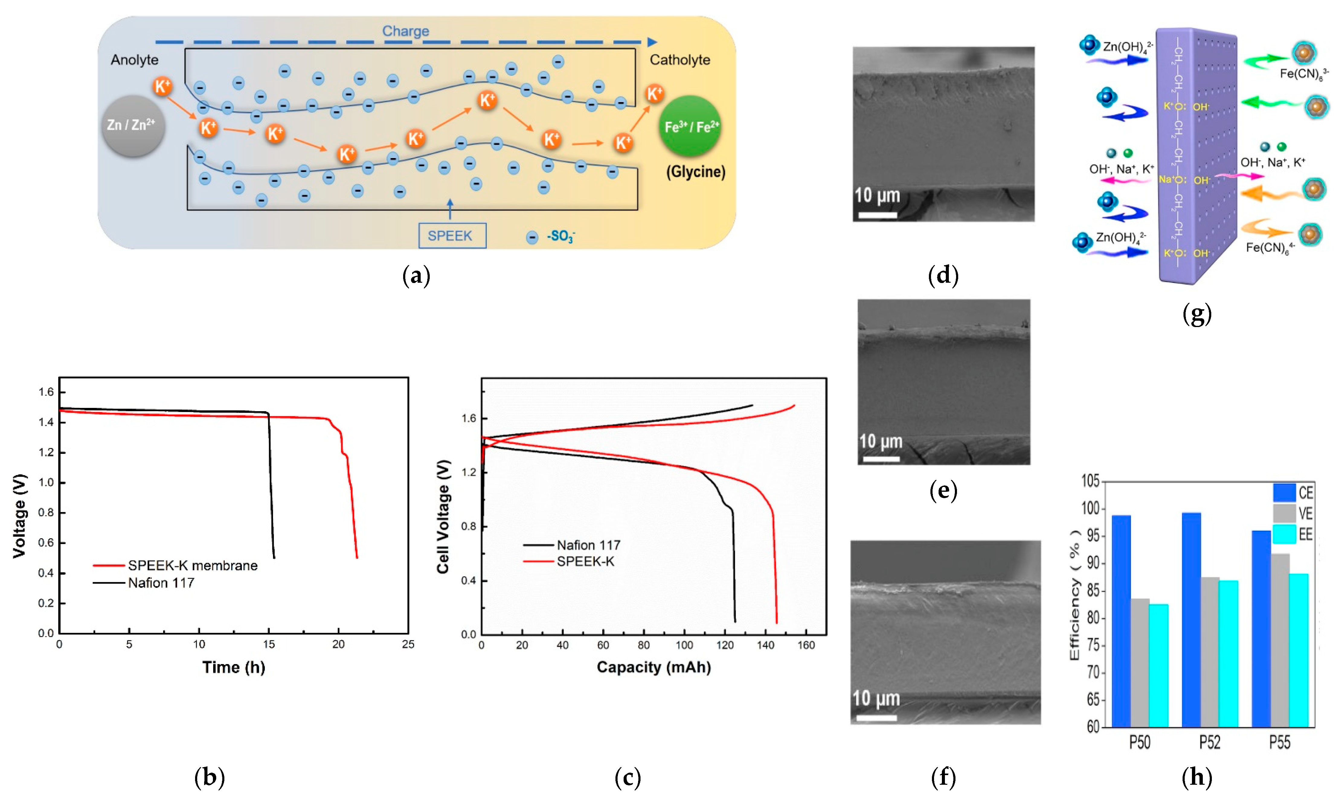
  95. Chang, S.; Ye, J.; Zhou, W.; Wu, C.; Ding, M.; Long, Y.; Cheng, Y.; Jia, C. A low-cost SPEEK-K type membrane for neutral aqueous zinc-iron redox flow battery. Surf. Coat. Technol. 2019, 358, 190–194. [Google Scholar] [CrossRef]
  96. Chen, D.; Kang, C.; Duan, W.; Yuan, Z.; Li, X. A non-ionic membrane with high performance for alkaline zinc-iron flow battery. J. Membr. Sci. 2021, 618, 118585. [Google Scholar] [CrossRef]
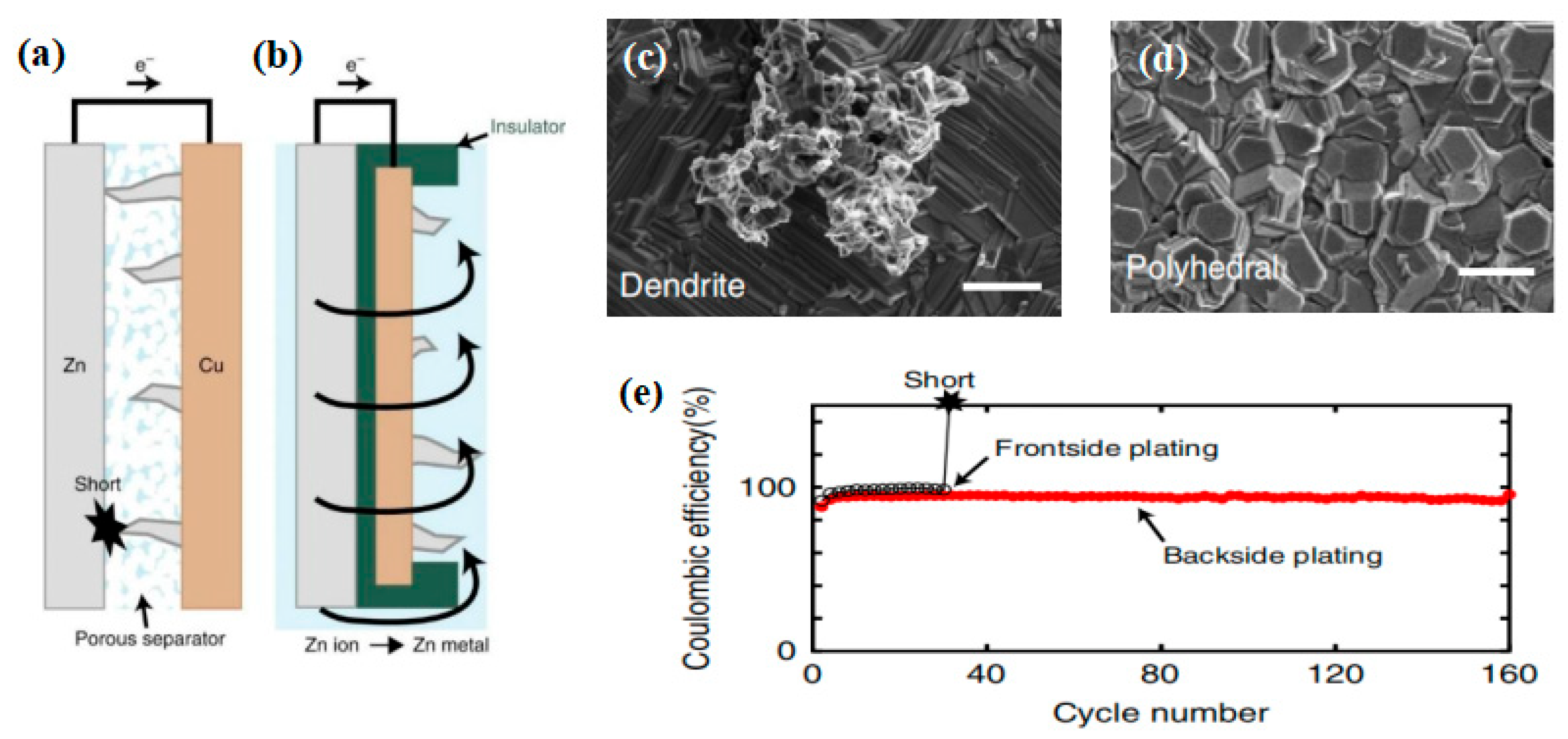
  97. Higashi, S.; Lee, S.W.; Lee, J.S.; Takechi, K.; Cui, Y. Avoiding short circuits from zinc metal dendrites in anode by backside-plating configuration. Nat. Commun. 2016, 7, 11801. [Google Scholar] [CrossRef] [Green Version]
  98. Kim, H.-I.; Shin, H.-C. SnO additive for dendritic growth suppression of electrolytic zinc. J. Alloy. Compd. 2015, 645, 7–10. [Google Scholar] [CrossRef]
  99. Zhang, Y.; Henkensmeier, D.; Kim, S.; Hempelmann, R.; Chen, R. Enhanced reaction kinetics of an aqueous Zn–Fe hybrid flow battery by optimizing the supporting electrolytes. J. Energy Storage 2019, 25, 100883. [Google Scholar] [CrossRef]
  100. Mitha, A.; Yazdi, A.Z.; Ahmed, M.; Chen, P. Surface Adsorption of Polyethylene Glycol to Suppress Dendrite Formation on Zinc Anodes in Rechargeable Aqueous Batteries. ChemElectroChem 2018, 5, 2409–2418. [Google Scholar] [CrossRef]
  101. Wang, K.; Pei, P.; Ma, Z.; Xu, H.; Li, P.; Wang, X. Morphology control of zinc regeneration for zinc–air fuel cell and battery. J. Power Sources 2014, 271, 65–75. [Google Scholar] [CrossRef]
  102. ShakeriHosseinabad, F.; Daemi, S.R.; Momodu, D.; Brett, D.J.L.; Shearing, P.R.; Roberts, E.P.L. Influence of Flow Field Design on Zinc Deposition and Performance in a Zinc-Iodide Flow Battery. ACS Appl. Mater. Interfaces 2021, 13, 41563–41572. [Google Scholar] [CrossRef] [PubMed]
  103. Yuan, Z.; Li, X. Ion conducting membranes for aqueous flow battery systems. Chemical Communications 2018, 54, 7570–7588. [Google Scholar] [CrossRef] [PubMed]
  104. Brown, P.L.; Ekberg, C. First Transition Series Metals. Hydrolys. Met. Ions 2016, 499–716. [Google Scholar]
  105. Huang, Q.; Wang, Q. Next-Generation, High-Energy-Density Redox Flow Batteries. ChemPlusChem 2015, 80, 312–322. [Google Scholar] [CrossRef]
  106. Hawthorne, K.L.; Wainright, J.S.; Savinell, R.F. Studies of Iron-Ligand Complexes for an All-Iron Flow Battery Application. J. Electrochem. Soc. 2014, 161, A1662–A1671. [Google Scholar] [CrossRef]
  107. Yuan, Y.F.; Tu, J.P.; Wu, H.M.; Wang, S.F.; Zhang, W.K.; Huang, H. Effects of stannous ions on the electrochemical performance of the alkaline zinc electrode. J. Appl. Electrochem. 2007, 37, 249–253. [Google Scholar] [CrossRef]
  108. Zhou, X.; Lin, L.; Lv, Y.; Zhang, X.; Wu, Q. A Sn-Fe flow battery with excellent rate and cycle performance. J. Power Sources 2018, 404, 89–95. [Google Scholar] [CrossRef]
  109. Zhang, C.; Guo, L.; Deng, C.; Huang, H.; Cheng, Y. Semi-solid reactive interfaces based on ZnO@C core-shell materials for zinc-iron flow batteries. Chem. Eng. Sci. 2022, 250, 117402. [Google Scholar] [CrossRef]
  110. Chu, F.; Guo, L.; Wang, S.; Cheng, Y. Semi-solid zinc slurry with abundant electron-ion transfer interfaces for aqueous zinc-based flow batteries. J. Power Sources 2022, 535, 231442. [Google Scholar] [CrossRef]
  111. Zhi, L.; Li, T.; Liu, X.; Yuan, Z.; Li, X. Functional complexed zincate ions enable dendrite-free long cycle alkaline zinc-based flow batteries. Nano Energy 2022, 102, 107697. [Google Scholar] [CrossRef]
  112. Wang, G.; Zou, H.; Xu, Z.; Tang, A.; Zhong, F.; Zhu, X.; Qin, C.; Ding, M.; You, W.; Jia, C. Unlocking the solubility limit of ferrocyanide for high energy density redox flow batteries. Mater. Today Energy 2022, 28, 101061. [Google Scholar] [CrossRef]
Figure 1. (a) Comparison of ZIRFB with the rest of RFB systems in line with energy density and cost; reproduced with permission from [44]. Copyright 2017, John Wiley and Sons. (b) A schematic diagram of an RFB; reproduced with permission from [45]. Copyright 2017, Elsevier. (c) The Pourbaix diagram of Zn species in aqueous solution with various pH values. Reproduced with permission from [18]. Copyright 2018, Elsevier.
Batteries 08 00202 g001
Figure 2. (a) Diagrammatic sketch of the growth and nucleation processes of Zn dendrites; reproduced under terms of the CC-BY license [76]. Copyright 2020, Frontiers. (b) The growth and dissolution of Zn dendrite at various points of time corresponding to (c); (c) chronopotentiometric curve of the zinc plating–stripping process according to the radiography measurements; (d) growth curves at three positions by probing the growth of the dendrite directly. Reproduced with permission from [77]. Copyright 2019, Elsevier.
Batteries 08 00202 g002aBatteries 08 00202 g002b
Figure 3. The simulation of zinc dendrite morphology (a), the distribution of ion concentration (b): OH, (c): Zn(OH)42−, and electric potential (d) at the same charging moment. Reproduced with permission from [78]. Copyright 2021, Royal Society of Chemistry. (e) Hydrolysis processes in Fe(III) solutions (numbers in parentheses give reaction times (s) at 25 °C). Reproduced with permission from [79]. Copyright 1984, American Chemical Society.
Batteries 08 00202 g003
Figure 4. Several key problems in a ZIRFB. Reproduced with permission from [44]. Copyright 2017, John Wiley and Sons. Reproduced with permission from [76]. Copyright 2020, Frontiers. Reproduced with permission from [82]. Copyright 2020, WILEY. Reproduced with permission. Reproduced with permission from [83]. Copyright 2020, American Chemical Society. Reproduced with permission from [84]. Copyright 2021, RSC Publishing.
Batteries 08 00202 g004
Figure 5. (a,b) The optical image of the zinc plate electrode (cross-section view) after charging (a) and discharging (b); (ch) morphologies of the carbon felt electrode after charging (ce) and discharging (fh) (magnified SEM images in (e,h)); (i,j) charge–discharge curve of the alkaline ZIRFB at 80 mA cm−2 with a carbon felt electrode (i) or with a zinc plate electrode (j). Reproduced with permission from [51]. Copyright 2018, Elsevier.
Batteries 08 00202 g005
Figure 6. Charge–discharge voltage profiles with different electrode porosity (a) and electrode thicknesses (b); comparison of performance between the various designs: the species distribution at a 50 percent stage of Zn(OH)42− (left side) and Fe(CN)63− (right side) during charge (c), and Zn(OH)42− (left side) and Fe(CN)64− (right side) during discharge (d). Reproduced with permission from [88]. Copyright 2021, Elsevier. (e) The total power loss including hydraulic losses (blue), electric transport losses (red), and internal electric losses (yellow) for the bulk electrode (left) and the optimized electrode (right). Reproduced with permission from [89]. Copyright 2021, Elsevier.
Batteries 08 00202 g006
Figure 7. (a) Schematic of ZIRFBs adopting a 3D porous CF and PBI membrane with excellent mechanical strength, and the transport principle of hydroxyl ions in the membrane; reproduced with permission from [51]. Copyright 2018, Elsevier. (b) Zn accumulation/dendrite of the ZIRFB when adopting the uncharged (up) and the negatively charged (down) porous membrane; (c) cycle performance for an alkaline ZIRFB between 80 and 160 mA cm−2 for 240 cycles; insets: charge–discharge profiles. Reproduced under terms of the CC-BY license [52]. Copyright 2018, Springer Nature.
Batteries 08 00202 g007aBatteries 08 00202 g007b
Figure 8. (a) Schematic illustration of ZIRFBs employing the SPEEK-K membrane; (b) the OCP curves of the single-cell with SPEEK-K and N117 membrane; (c) the second cycle charge–discharge curves of SPEEK-K and N117 membrane at 40 mA cm−2; reproduced with permission from [95]. Copyright 2019, Elsevier. Cross-section morphologies of P50 (d), P52 (e), and P55 (f); (g) schematic illustration of a non-ionic membrane in a ZIRFB; (h) the efficiencies of ZIRFBs assembled with various membranes in (df) under 80 mA cm−2. Reproduced with permission from [96]. Copyright 2021, Elsevier.
Batteries 08 00202 g008
Figure 9. Schematic illustration: (a) frontside-plating configuration and (b) backside-plating configuration; SEM image (scale bars, 2 mm) of Cu substrate surface from the (c) frontside-plating and (d) backside-plating configurations after 20 cycles; (e) the cell stability curves compared the front with backside configurations (20 mA cm−2). Reproduced under terms of the CC-BY license [97]. Copyright 2016, Springer Nature.
Batteries 08 00202 g009
Figure 10. (a) SEM images of the Zn electro-deposits obtained at 40 mA cm−2 and in the electrolyte comprising 3 × 10⁻³ M SnO; reproduced with permission from [98]. Copyright 2015, Elsevier; SEM images of the Zn metal after charge–discharge cycling with various supporting electrolytes: (b) deionized water, (c) NH4Cl (1.0 M), (e) CaCl2/H2O (3.5 m), (f) CaCl2/H2O (3.5 m) + NH4Cl (0.5 M); CV curves of ZnCl2 (10 mM) + NH4Cl (x M, x = 0, 0.2, 0.5, 1.0), (d) and CaCl2/H2O (3.5 m) + NH4Cl (x M, x = 0, 0.2, 0.5, 1.0) (g); (h) Charge/discharge cell performance; (i) battery efficiencies at 20 mA cm−2. Reproduced with permission from [99]. Copyright 2019, Elsevier. (j) Schematics of PEG200 electrolytes effecting on Z-P/S process; reproduced with permission from [100]. Copyright 2018, John Wiley and Sons; (k) numerical simulations of the Zn2+ flux distribution at different deposition times. Reproduced with permission from [35]. Copyright 2022, American Chemical Society.
Batteries 08 00202 g010aBatteries 08 00202 g010b
Figure 11. (a) The species distribution at different flow rates at the 50% stage during charge (up: left side is Zn(OH)42−, right side is Fe(CN)63−) and discharge (down: left side is Zn(OH)42−, right side is Fe(CN)64−). Reproduced with permission from [87]. Copyright 2021, Elsevier; (b) deposited zinc morphologies in weight 40% KOH with 1 M zinc oxide with electric quantity for 10 min at the current density of 100 mA cm−2: quiescent electrolyte (up) and flowing electrolyte (down). Reproduced with permission from [101]. Copyright 2014, Elsevier; (c) dendrite morphology (up) and Zn(OH)42− concentration distribution (down) diagram at different flow rates (0.001 m·s-1, 0.004 m·s-1, 0.008 m·s-1). Reproduced with permission from [78]. Copyright 2021, Royal Society of Chemistry.
Batteries 08 00202 g011
Figure 12. (a) CV curves comparison of Fe2+ complexing ligands at the scanning rate of 30 mV s−1 (20 cycles average); (b) Fe2+-pyridine complex forms as a result of the molar ratio when pH < 2; reproduced with permission from [82]. Copyright 2020, Elsevier. (c) CV curves of 50 mM FeCl2 in different aqueous ionic liquid solutions; reproduced with permission from [99]. Copyright 2019, Elsevier. Cycling performance of the battery with glycine (d,e), malic acid (f), malonic acid (g); (h) theoretical calculations of radii and bond energies. Reproduced with permission from [44]. Copyright 2017, John Wiley and Sons.
Batteries 08 00202 g012
Figure 13. (a) Representation of the neutral ZIRFB (Catholyte: K3Fe(CN)6 + KBr; Anolyte: ZnBr2 + KBr); (b) cycling performance of neutral ZIRFB at 30 mA cm−2; reproduced with permission from [56]. Copyright 2022, Elsevier. (c) Representation of the neutral ZIRFB adopted FeCl2/ZnBr2 as the redox couples; (d) CV curves of the electrolyte on the graphite electrode at 10 mV s−1; (e) charge–discharge curve at 40 mA cm−2. Reproduced with permission from [44]. Copyright 2017, John Wiley and Sons.
Batteries 08 00202 g013
Figure 14. (a) CV curves of Zn/Zn2+ on graphite electrode; (b) the ZIRFB performance with and without HAc/NaAc buffer. Reproduced with permission from [53]. Copyright 2016, Elsevier.
Batteries 08 00202 g014
Figure 15. (a) Schematic of an acidic ZIRFB with mixed electrolytes; (b) CV curves for three Zn/Fe ratios (titanium substrate, pH = 1); (c) cell potential change during testing time; (d) VE, CE, and EE changes during continuous charge–discharge cycling (T = 25 °C). Reproduced under terms of the CC-BY license [54]. Copyright 2017, IOP Publishing. (e) Schematic of the acid-base mixed ZIRFB; (f) Charge–discharge tests (SOC = 75%). The dash lines and solid lines represent the charging process and the discharging process, respectively; (g) cell polarization curves (SOC = 70%). Reproduced under terms of the CC-BY license [55]. Copyright 2015, Royal Society of Chemistry (RSC Publishing).
Batteries 08 00202 g015
Figure 16. The comparison with potential approaches in terms of efficiencies and current density.
Batteries 08 00202 g016
Table 1. Comparison of VRFBs and ZBRFBs.
RFBCharacteristicEnergy Density/Wh L−1EE/%Life CycleRef.
VRFBsBoth active materials used in catholytes and anolytes are vanadium species, and they exhibit good durability and reversibility, suitable for long-term energy storage.15–2582.7 (120 mA/cm2)1000[33]
76.3 (300 mA/cm2)500[34]
ZBRFBsThere are a wide range of catholyte/anolyte sources, and the advantages of low-cost zinc species are significant. The operating environment can be classified as acidic, neutral and alkaline, thus, having a wide pH range.>5087.6 (200 mA/cm2)500[35]
Table 2. The comparison of the ZIRFB system with conventional liquid–liquid RFB systems.
Types of RFB SystemsPotential/VOperating Current Density/mA cm−2Operating Temperature/°CPeak Power Density/mW cm−2Refs.
Alkaline zinc/iron1.7435–160R.T.1056[51,52]
Acidic zinc/iron1.5325–1502537.8[53,54,55]
Neutral zinc/iron1.4320–80R.T.273[44,56]
All-vanadium1.2610–50025–302780[29,57,58]
Iron–chromium1.1840–48055–65216[59,60]
Iron–vanadium1.0250R.T.≈50[61,62]
All-iron1.3440R.T.160[63]
Polysulfide/iodide1.055–37R.T.84.6[19,20]
Quinone/bromide0.89200–50020–451000[21,22]
Quinone/iron1.20100R.T.240[64,65]
Polymer-based1.1020–2825-[66]
R.T. = room temperature.
Table 3. The difference in various zinc-based RFBs.
Zinc-Based RFBCharacteristicsRef.
Zn–Fe (Alkaline)Ecell (in theory)/V1.74
Advantage• High OCV;
• Long-term cycling;
• Cost-effective porous separator/membrane high current density.
Disadvantage• Zinc dendrites;
• High separator/membrane resistance;
• Low solubility of ferrocyanide.
CatholytesFe(CN)64−↔Fe(CN)63− + e E (vs. Hg/HgO) = +0.33 V
AnolytesZn(OH)42− + 2e↔Zn + 4OH E (vs. Hg/HgO) = −1.41 V
ElectrodeCarbon felts[52]
MembraneA nanoporous poly (ether sulfone)/sulfonated poly (ether ether ketone) (PES/SPEEK) membrane
PerformanceEE ≈ 91.92% (40 mA cm−2, 240 cycles)
Zn–Fe (Acidic)Ecell (in theory)/V1.53
Advantage• High solubility of iron ions;
• Fast kinetics of Fe2+/Fe3+.
Disadvantage• Zinc dendrites;
• Hydrogen evolution.
CatholytesFe2+↔Fe3+ + e E (vs. SHE) = +0.77 V
AnolytesZn2+ + 2e↔Zn E (vs. SHE) = −0.76 V
ElectrodeGraphite plate[54]
MembraneDaramic 175
PerformanceEE ≈ 68% (25 mA cm−2, 127 cycles)
Zn–Fe (Neutral)Ecell (in theory)/V1.43
Advantage• Low cost.
Disadvantage• Zinc dendrites.
• Fen+ hydrolysis.
CatholytesFe(Glycine)22+↔Fe(Glycine)23+ + e E (vs. Ag/AgCl) = +0.55 V
AnolytesZn2+ + 2e↔Zn E (vs. Ag/AgCl) = −0.88 V
ElectrodeCarbon felts[35]
MembraneA perfluorinated sulfonic acid membrane
PerformanceEE ≈ 87.6% (200 mA cm−2, 500 cycles)
Zn–Br2 (Neutral)Ecell (in theory)/V1.84
Advantage• Low cost;
• High-energy density.
Disadvantage• Zinc dendrites;
• Environmental risk;
• Slow reaction kinetics.
CatholytesZnBr2
AnolytesZnBr2
ElectrodeGraphite felts[68]
MembraneNafion 212
PerformanceEE ≈ 75% (40 mA cm−2, 50 cycles)
Zn–I2 (Neutral)Ecell (in theory)/V1.37
Advantage• High-energy density.
Disadvantage• Zinc dendrites;
• The instability of the catholyte.
CatholytesZnI2/NH4I
AnolytesZnCl2
ElectrodeGraphite felts[69]
MembraneNafion 115
PerformanceEE ≈ 80% (10 mA cm−2, 2500 cycles)
Zn–Ce (Acidic)Ecell (in theory)/V2.4
Advantage• High OCV;
• High-energy density.
Disadvantage• Zinc dendrites;
• Low solubility of Ce3+/Ce4+ species.
CatholytesCe(CH3SO3)3
AnolytesZn(CH3SO3)2
ElectrodeCarbon polyvinyl-ester composite[70]
MembraneNafion 117
PerformanceEE ≈ 73% (50 mA cm−2)
Zn–Ni (Alkaline)Ecell (in theory)/V1.71
Advantage• High-energy density;
• Low cost.
Disadvantage• Poor kinetics;
• Low-energy density;
• Oxygen evolution.
CatholytesNi(OH)2
AnolytesZnO
ElectrodeNickel-based[71]
Membrane-
PerformanceEE ≈ 80.1% (80 mA cm−2, 200 cycles)
Zn–Air (Alkaline)Ecell (in theory)/V>1.6
Advantage• The extensive global reserves of Zn;
• Non-flammable electrolytes.
Disadvantage• Zn dissolution/precipitation;
• Slow reaction kinetics.
Catholytes-
AnolytesK2[Zn(OH)4]
Electrode3D-wired Zn electrodes[72]
MembraneAn aqueous-compatible separator
PerformanceSpecific capacity ≈ 694 ± 20 mAh·gZn−1 (24 mA cm−2)
Table 4. The diffusion coefficients of Fe3+ (DFe3+) and Fe2+ (DFe2+) in different solutions.
Active AgentDFe3+ (×10−6)/cm2 s−1DFe2+ (×10−6)/cm2 s−1
BMImCl6.395.53
Glycine2.904.08
Malic acid1.904.20
Malonic acid3.803.20
Xylitol0.273.20
Table 5. The comparison with potential approaches.
Batter.Potential ApproachesAdvantagesDisadvantagesCurrent Density/mA cm−2CyclesEE/%Peak Power Density/mW cm−2Refs.
Alkaline ZIRFBCarbon felt electrode, PBI membraneZinc dendrite prevention, low costPBI membrane has lower conductivity than Nafion80–160>15082.78 (160 mA cm−2)≈250[51]
Carbon felt electrode, PES/SPEEK membraneZinc dendrite preventionThe long-term durability of the SPEEK-based membrane requires further verification80–1609078.76 (160 mA cm−2)1050 (1040 mA cm−2)[92]
Semi-solid anodes:graphite felt and ZnO@MC slurryZinc dendrite preventionLimited current density range5–1546074.8 (10 mA cm−2)-[109]
zinc slurry anodesZinc dendrite preventionLimited current density range10–406578 (40 mA cm−2)-[110]
Carbon felt electrode, SPEEK-K membraneLow costThe long-term durability of the SPEEK-based membrane requires further verification10–603078 (40 mA cm−2)-[95]
SPEEK-PES-PEG membraneCost-effectiveThe long-term durability of the SPEEK-based membrane requires further verification80–18012084.44 (80 mA cm−2)987 (920 mA cm−2)[96]
Electrolyte additive: Na2SO4, PBI membraneSuppress water migrationAggravates HER with the increased alkalinity of the electrolyte8012088 (80 mA cm−2)-[83]
A THEED additiveZinc dendrite prevention, suppresses water migrationThe additives are corrosive and irritants8016085 (80 mA cm−2)-[111]
K4Fe(CN)6 in NaOH solution, Nafion-Na+ membraneImproves solubilityAlthough the combination of cyanide ion and iron in the molecule is firm, potassium ferrocyanide still has certain toxicity50–500760088.1 (100 mA cm−2)656.81 (100 mA cm−2)[112]
Neutral ZIRFBElectrolyte additive:nicotinamideCost-effective, non-toxicLimited current density range10–5040070 (50 mA cm−2)185 (300 mA cm−2)[35]
Electrolyte additive: glycine, PBI membraneLow cost, alleviates hydrolysisPBI membrane has lower conductivity
than Nafion
20–8010086.66 (40 mA cm−2)-[44]
Supporting electrolyte: KBr, additive in the anolyte: ZnBr2Improves the Zn/Zn2+ redox reversibility, low chemical costComplex composition and not environmentally friendly due to the usage of bromide10–120200086.7 (30 mA cm−2)273 (376 mA cm−2)[44,56]
Acid ZIRFBFe(II)-pyridine complex solutionSuppression of ferrihydrite formationLimited current density range2010076.82 (20 mA cm−2)-[82]
HAc/NaAc in the negative electrolyteHER-suppressed, zinc dendrite preventionMembrane with high selectivity, efficiency decay of full-life cell performance (200 cycles)305071.1 (30 mA cm−2)37.8 (30 mA cm−2)[53]
Hybird ZIRFBMixed ZnCl2-FeCl2 electrolytes in mildly acidic chlorideCrossover-tolerant and microporous separatorsA pressure imbalance leading a gradual transfer of fluid from positive to negative2512768 (25 mA cm−2)-[54]
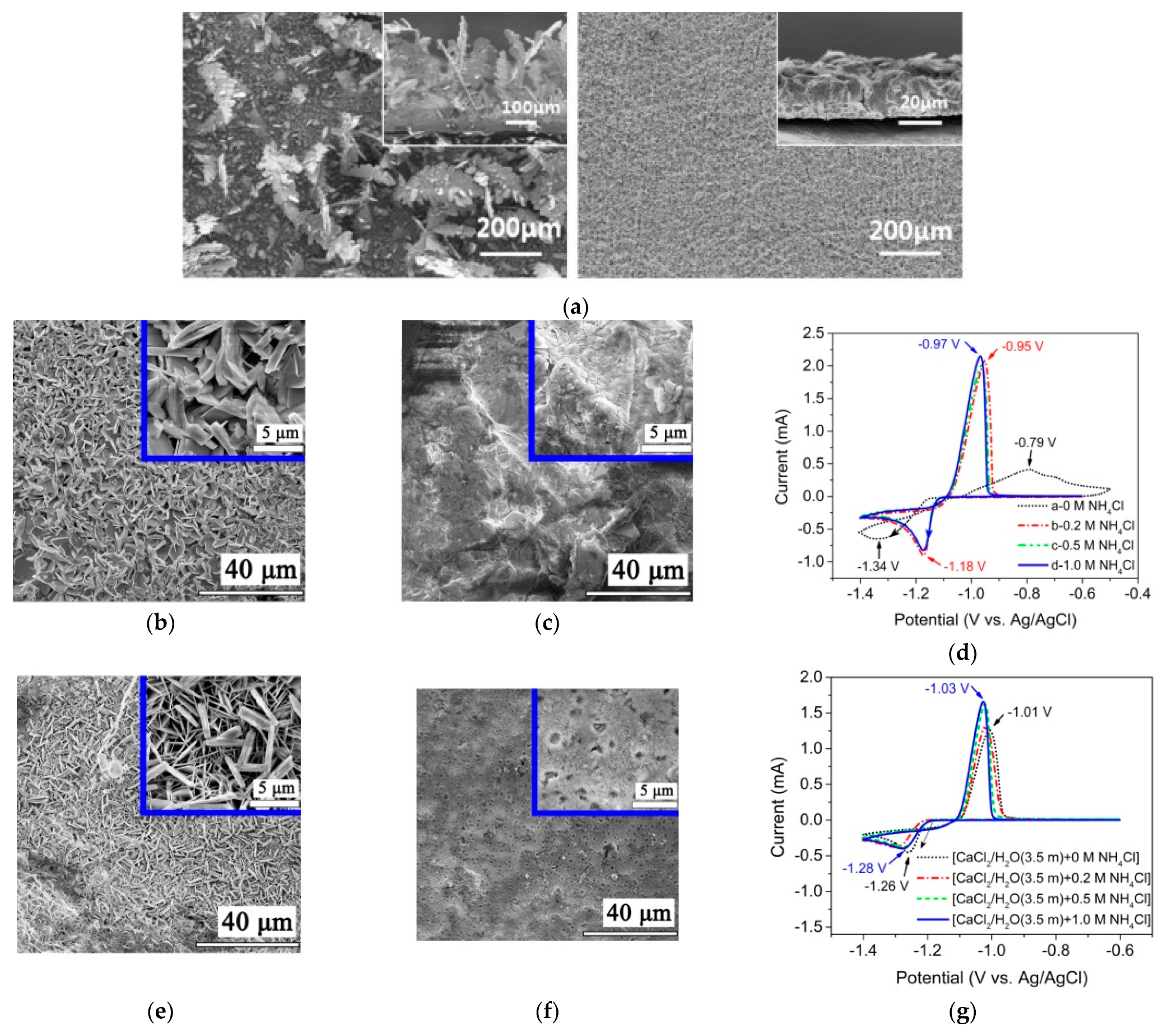
Fe species in BMImCl/H2O (8 m) with HCl (1 M) as catholyte, Zn species inCaCl2/H2O (3.5 m) with NH4Cl (0.5 M) as anolyteEnhances the redox activitiesLimited current density range10, 2015080 (20 mA cm−2)-[99]
A double-membrane designLow system capital cost, high OCV, facile kineticsComplex system design and long-term durability requires further verification50–1502075.9 (20 mA cm−2)676 (660 mA cm−2)[55]
Publisher’s Note: MDPI stays neutral with regard to jurisdictional claims in published maps and institutional affiliations.

