

Review of Thermal Management Strategies for Cylindrical Lithium-Ion Battery Packs

Abstract
:1. Introduction
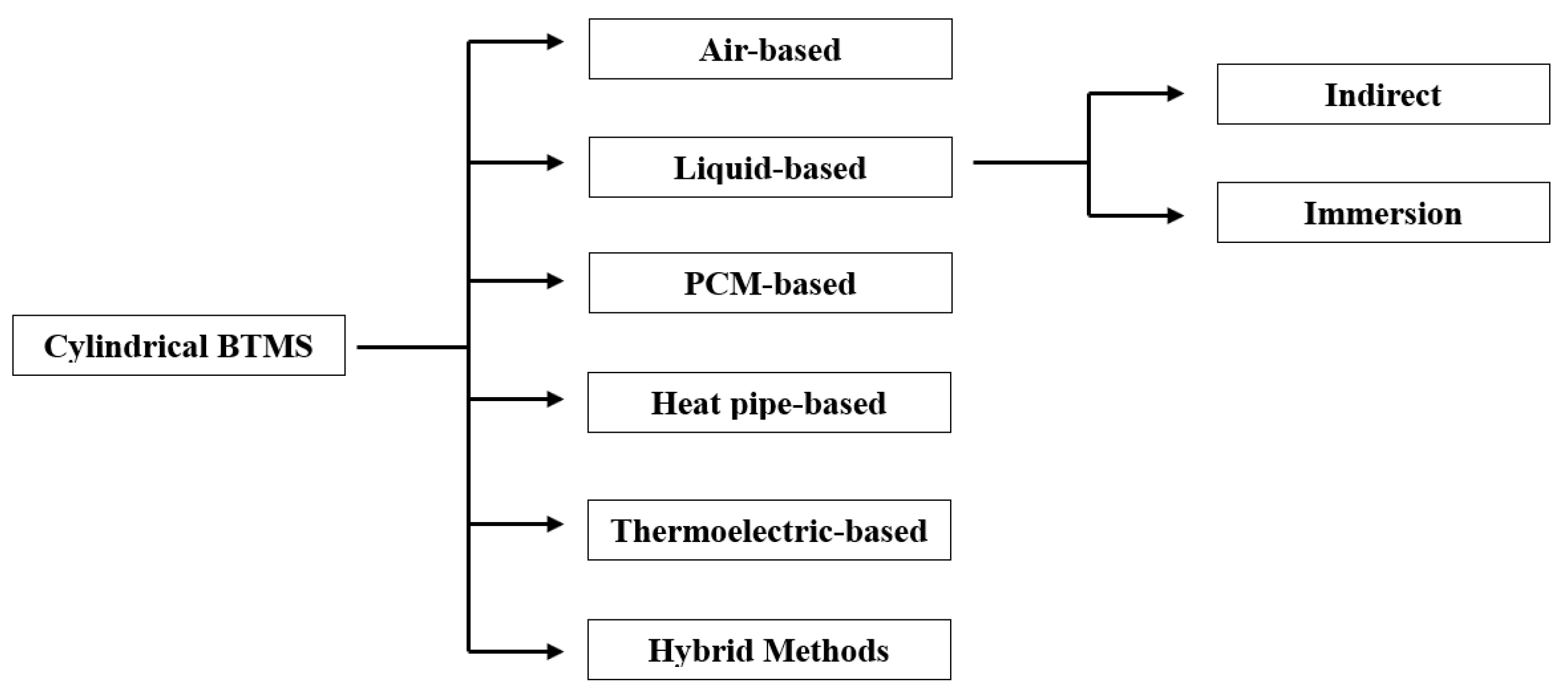
2. Battery Thermal Management Systems (BTMS)
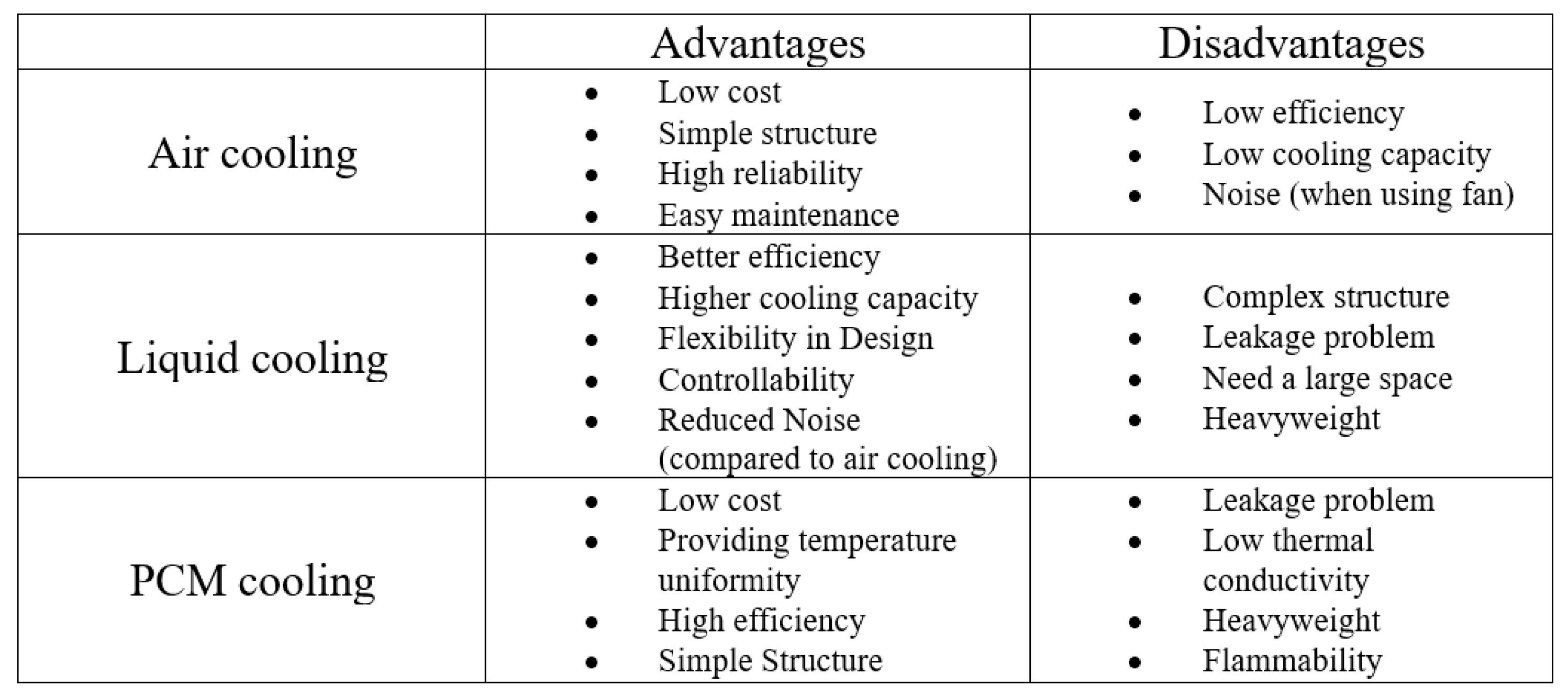
2.1. Air-Cooled BTMS
2.2. Liquid-Cooled BTMS
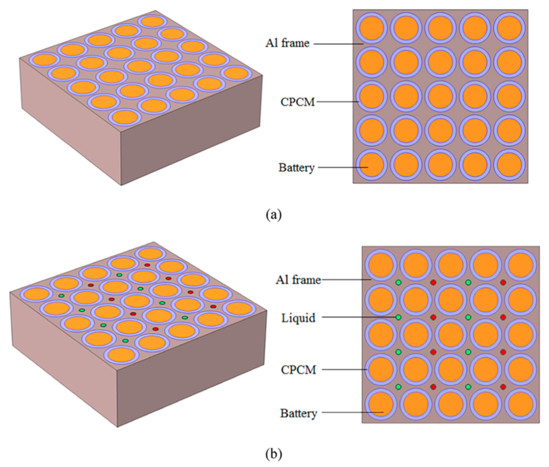
2.3. PCM-Cooled and PCM-Fin BTMS
2.4. Hybrid BTMS
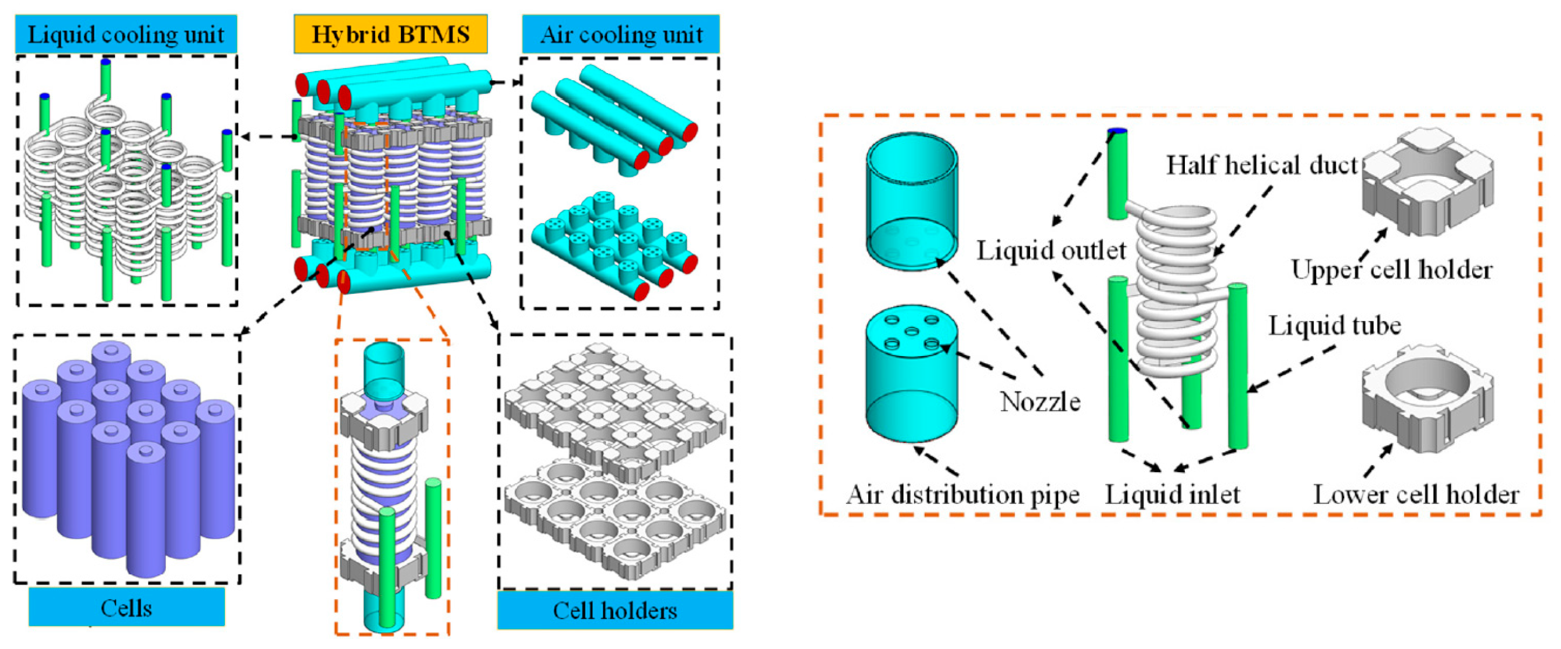
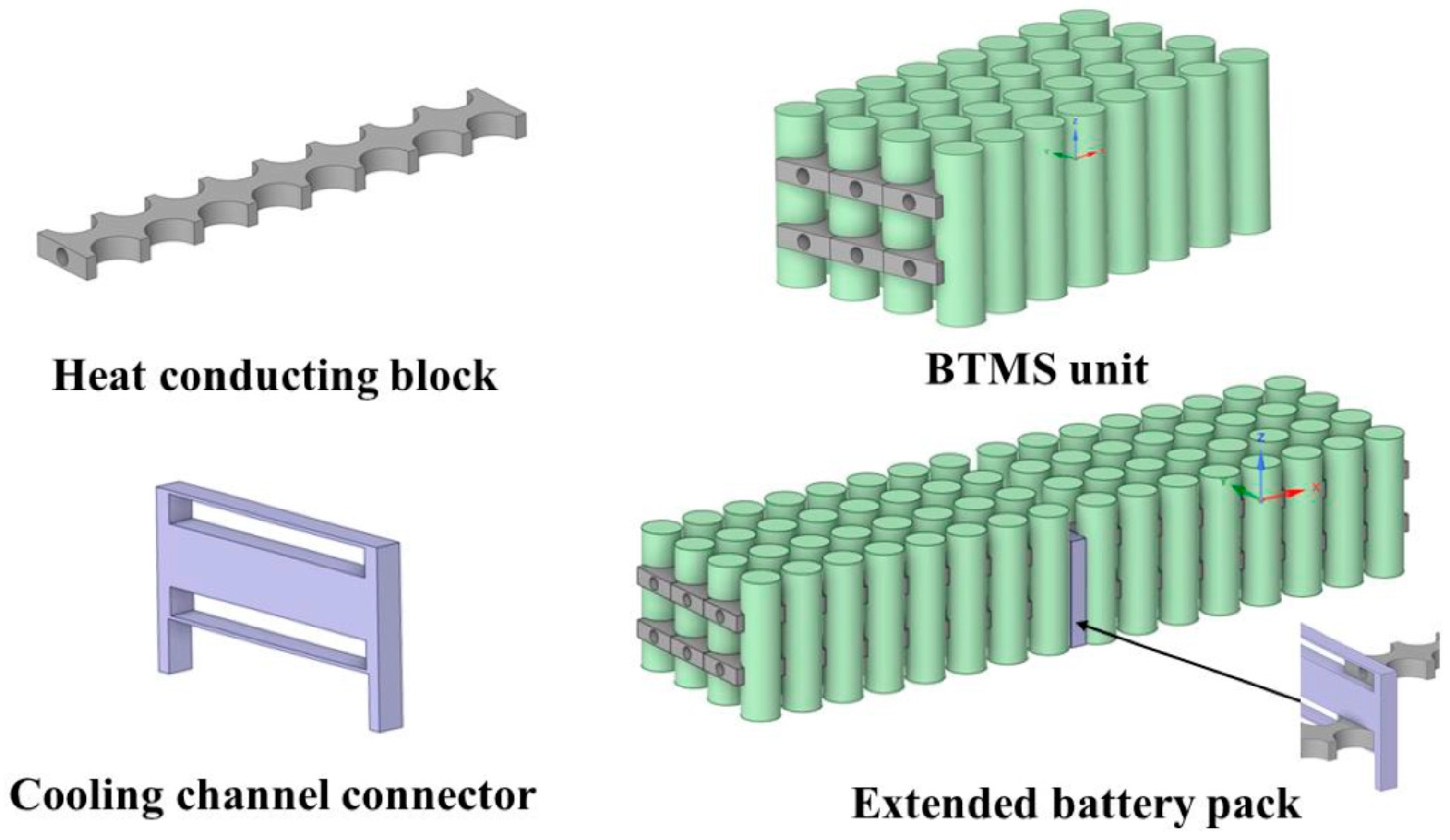
2.4.1. Combining Air Cooling and Liquid Cooling
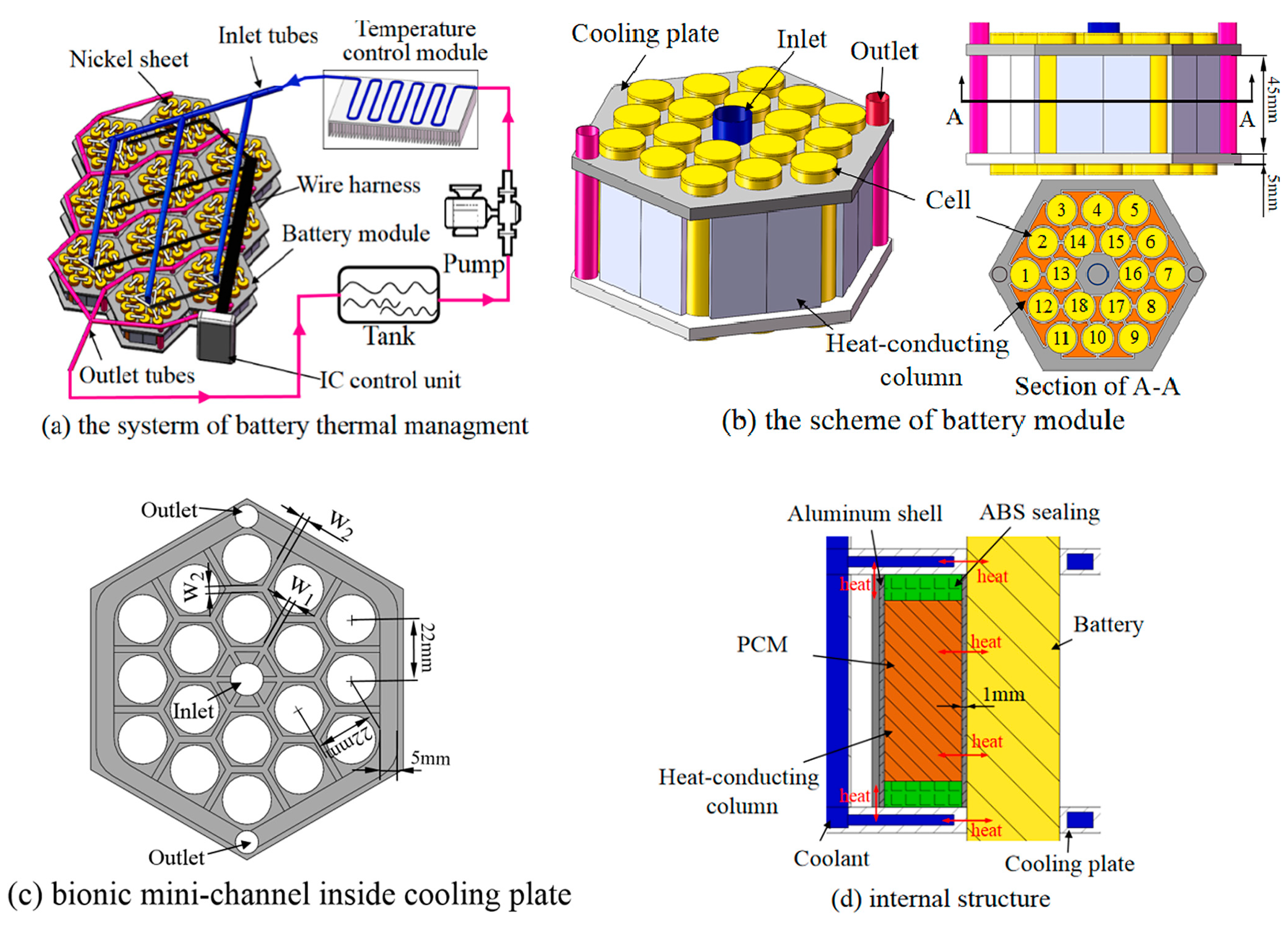
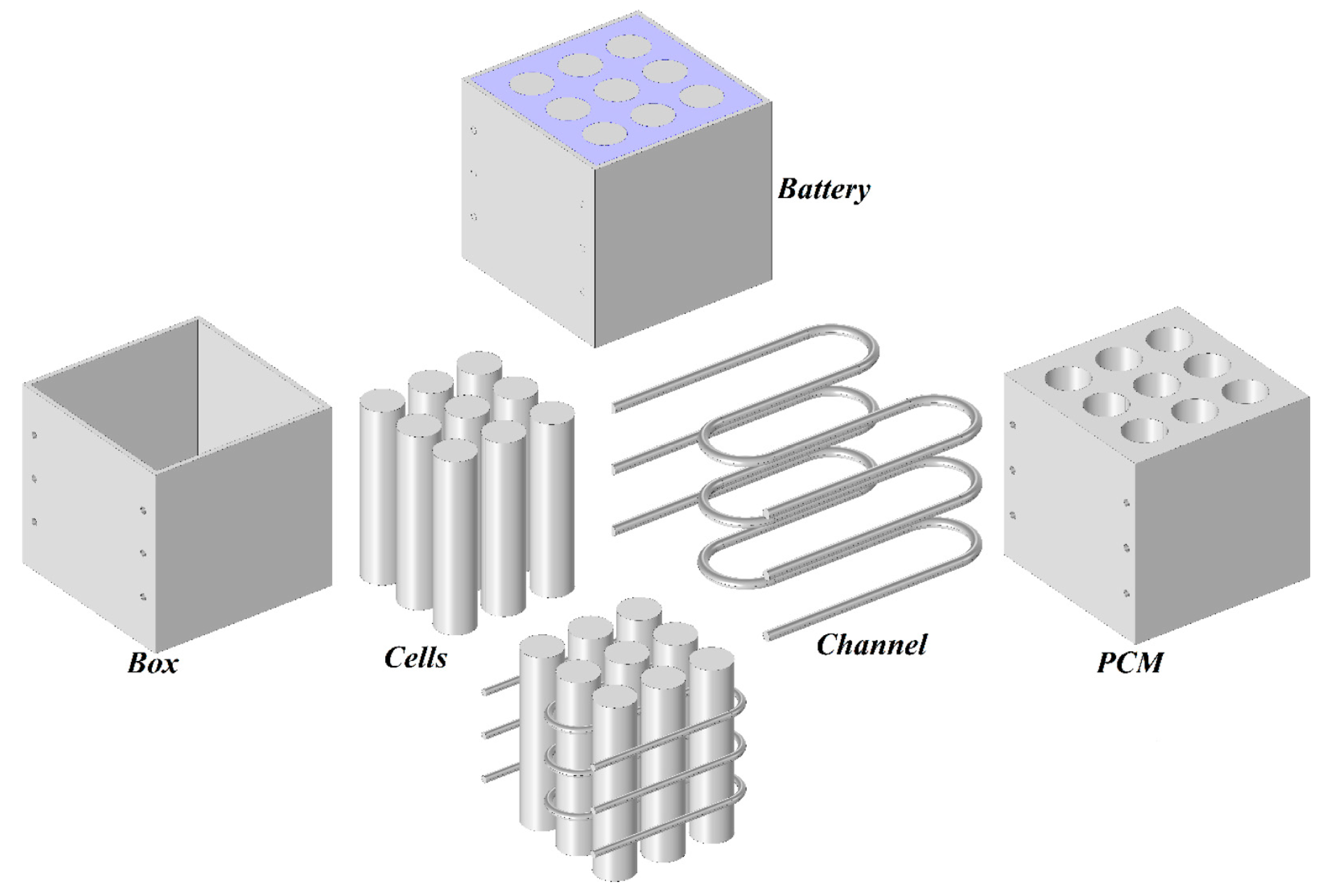
2.4.2. Combining PCM Cooling and Liquid Cooling
2.4.3. Combining Liquid Cooling and Heat Pipe
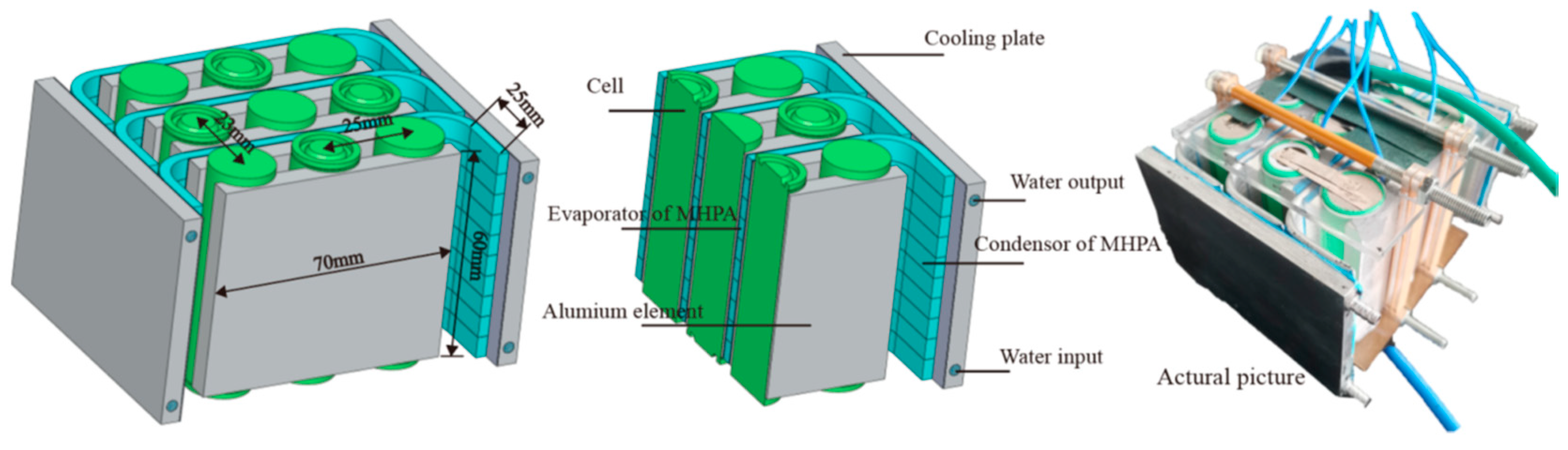
2.4.4. Combining PCM Cooling and Heat Pipes
3. Conclusions and Future Prospective
Author Contributions
Funding
Data Availability Statement
Acknowledgments
Conflicts of Interest
Appendix A

| Reference | Method | Type | Number | Load | Arrangement | Flow Regime | Airflow | Tmax (K) | ∆T (K) | Main Focus | Other Objectives |
|---|---|---|---|---|---|---|---|---|---|---|---|
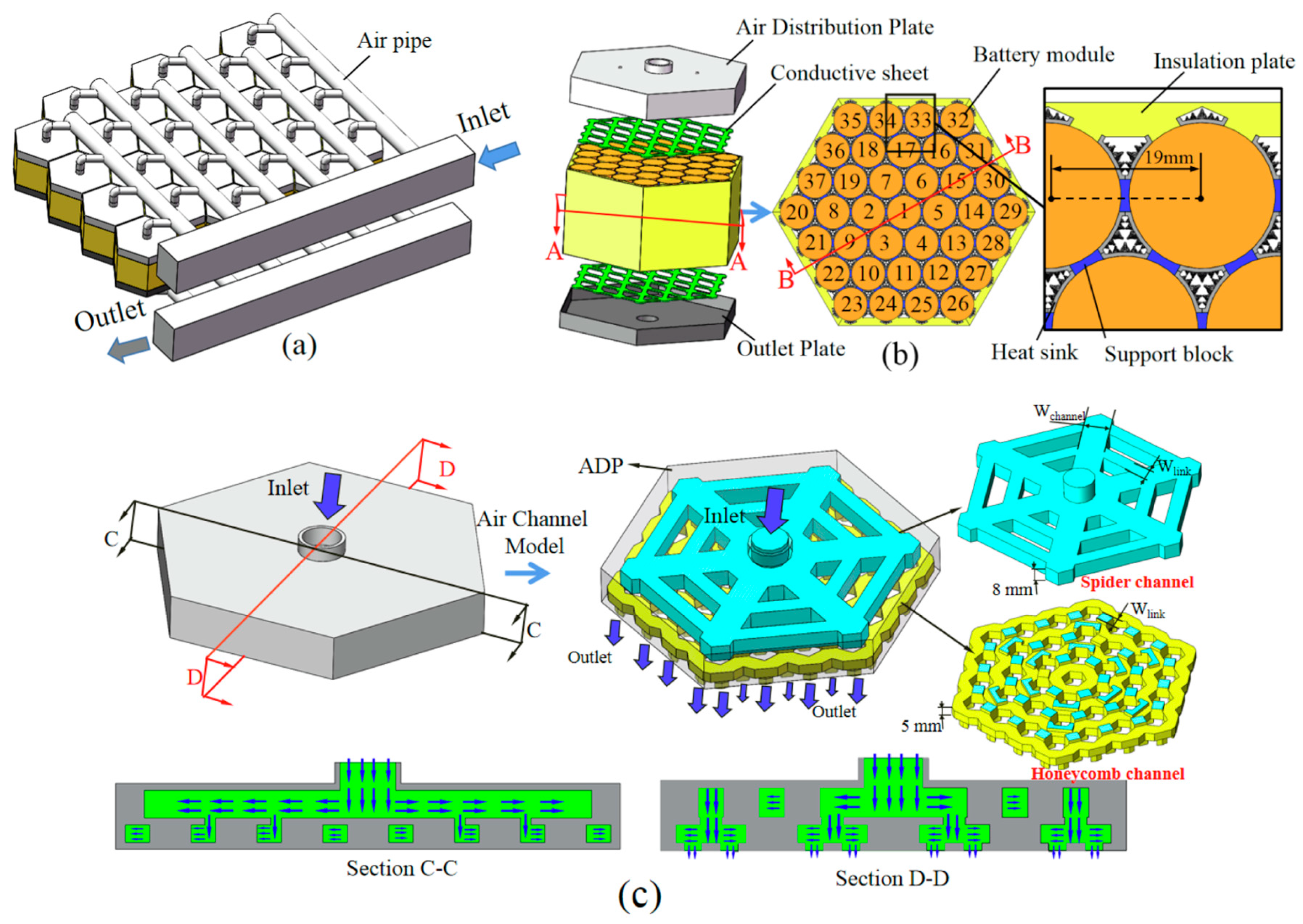
| Yang et al. [10] | Exp-Num | 18650 | 37 | 3 | Hexagonal | Turbulent | 8–12 m/s | 311 | 1.7 | Air distribution plate | Structure parameters |
| Zhou et al. [36] | Exp-Num | 18650 | 9 | 3–5 | Aligned | Laminar | 48 L/min | 305.7 | 3 | Air distribution pipe | Inlet pressure, discharge rate |
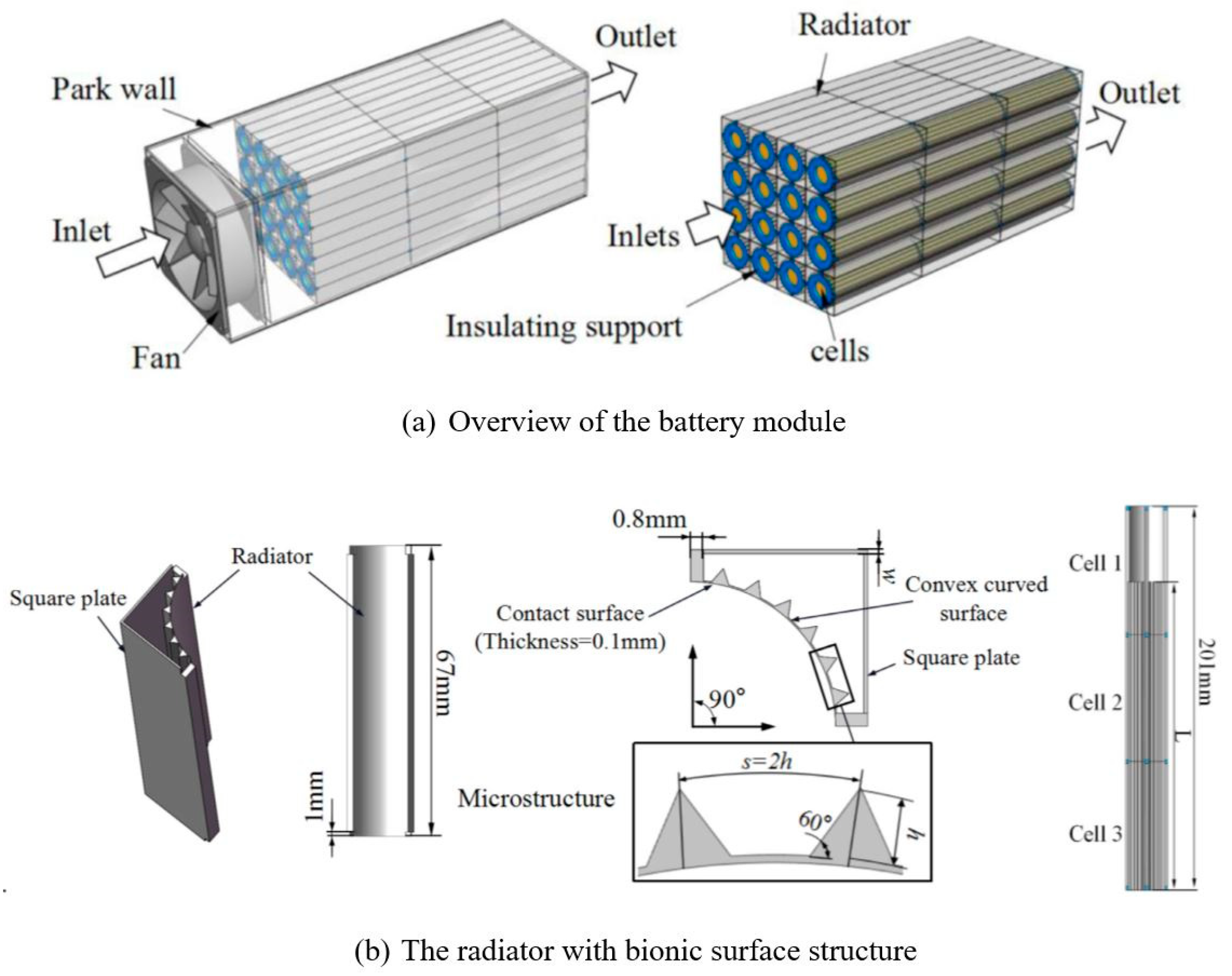
| Yang et al. [35] | Exp-Num | 18650 | 1 | 3 | - | Laminar | 0.1–1.5 m/s | 308 | 5 | Optimization, bionic surface structure | Structure parameter, inlet velocity |
| Zhou et al. [90] | Exp-Num | 18650 | 1 | 5 | - | Laminar | 0.1–1 m/s | 310.191 | 1.978 | Optimization, honeycomb cooling structure | Structure parameter |
| Hasan et al. [91] | Num | 18650 | 52 | N.M | Staggered | Turbulent | Re = 1.5–3 × 10⁴ | 324 | 3.5 | Turbulence intensity | Reynolds number |
| Zhao et al. [92] | Num | 18650, 26650, 42110 | 24 | 5 | Aligned | Turbulent | 0.1–10 m/s | 307 | 4 | Gap spacing, environment temperatures | |
| Li et al. [93] | Exp-Num | N.M | 32 | N.M | Aligned | Laminar | 0.02–20 m/s | 310 | 3.5 | ||
| Kummitha et al. [38] | Num | 32700 | 9 | 5 | Aligned | Turbulent | N.M | 301.5 | 0.26 | Cell holders’ jacket fins | |
| Hai et al. [94] | Num | N.M | 50 | N.M | Aligned | Re = 400 | 301 | 0.93 | Structure parameter | ||
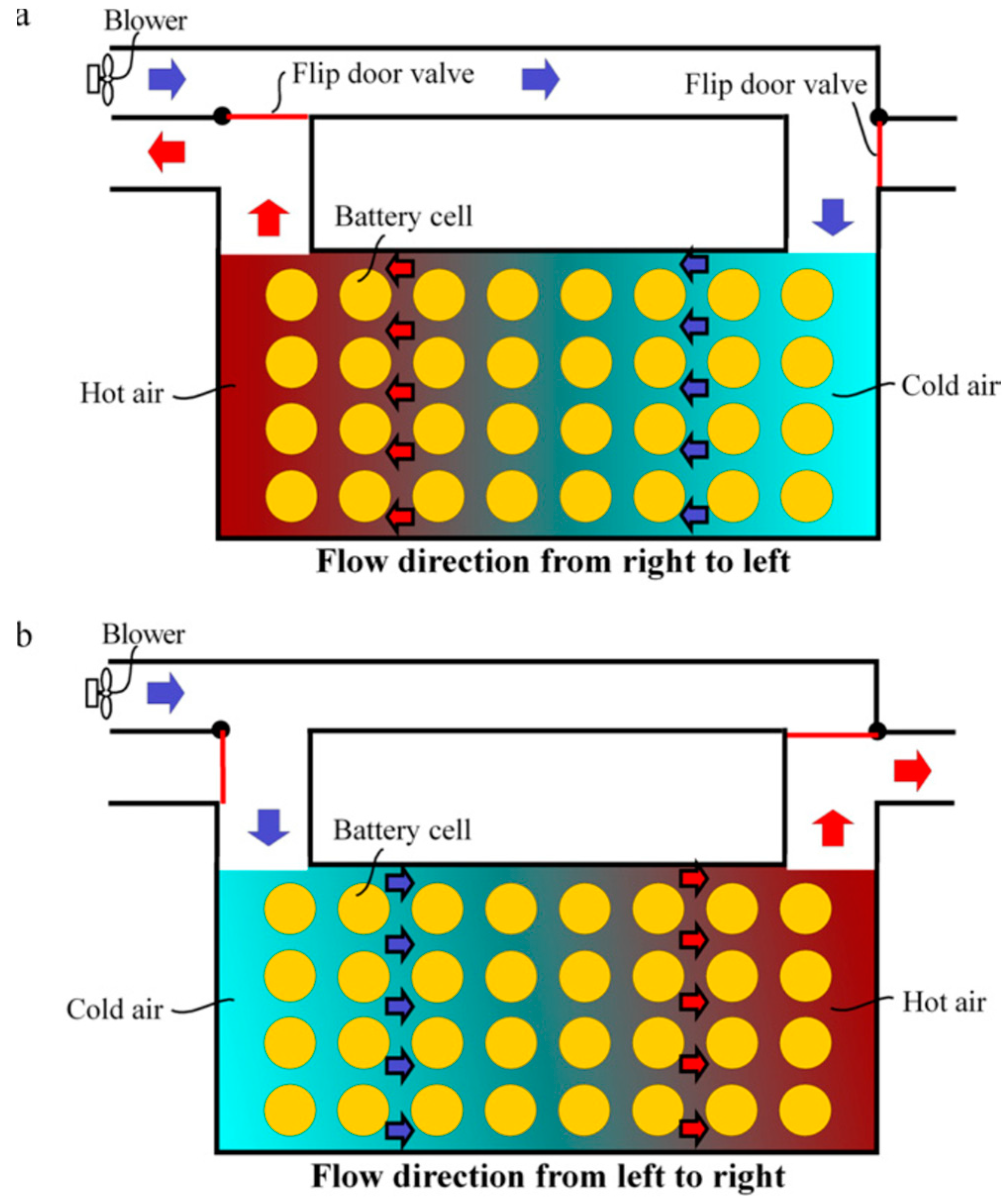
| Mahamud et al. [43] | Num | N.M | 8 | 1–10 | Aligned | Turbulent | 1 m/s | 303 | 4 | Reciprocating flow | Reciprocation period, cell spacing, coolant flow rate |
| Lu et al. [39] | Num | 18650 | 14 | 0.5 | Stagger-arranged | Laminar | 10−4 kg/s | 303.6 | 10.5 | Channel size, inlet and outlet locations, channel length | |
| Ji et al. [40] | Exp-Num | 18650 | 16 | 0.6–2 | Aligned | Laminar | 0.001 m/s | 307 | 2.7 | Optimization | Structure parameters |
| Wang et al. [44] | Num | 18650 | 24 | 1.5 | Aligned | Turbulent | 2–5 m/s | 304.5 | 0.97 | Optimization | Structure parameters |
| Li et al. [95] | Exp-Num | 21700 | 1 | 0.5 | - | N.M | 300 | Optimization | |||
| Saechan et al. [96] | Num | 18650 | 40 | 0.5–2 | Aligned | Turbulent | 1 m/s | 315 | 5.2 | Structure parameters | |
| Ruhani et al. [97] | Num | 18650 | 9 | 1 | Aligned | Laminar | Re = 80–140 | Reyolds number | |||
| Kausthubharam et al. [41] | Num | 18650 | 36 | 1.4 | Aligned | Laminar | 0.1–1 m/s | 304.2 | 0.4 | Thermal interface material | Structural and operational parameters on |
| Xun et al. [98] | Num | 18650 | 20 | 2 | Aligned | Laminar | N.M | 319 | 5 | Number of cooling channels, channel size | |
| Zhao et al. [99] | Num | 18650 | 71 | 5 | Stagger-arranged | Laminar | 0.1 m/s | 310 | 0.7 | Multiple short channels | Structural and operational parameters on |
| Yang et al. [100] | Exp-Num | 18650 | 8 | 1–4 | Aligned | Turbulent | 0.87–1.03 m/s | 305 | 2.1 | Structure parameters | |
| Fan et al. [101] | Num | 18650 | 32 | 0.6–4 | Aligned, staggered, and cross | Laminar—Turbulent | 0.1–10 m/s | 305 | 1.4 | Discharge rate, inlet temperature, energy efficiency | |
| Cen et al. [102] | Exp-Num | 18650 | 1 | 0.5–1.5 | - | N.M | N.M | 305 | 1.5 | ||
| E et al. [103] | Exp-Num | 18650 | 60 | 0.5–1 | Aligned | Laminar | 2 m/s | 307.2 | 2.4 | Structure parameters | |
| Chen et al. [104] | Num | 18650 | 50 | Laminar | 309.2 | ||||||
| Hai et al. [105] | Num | 18650 | 16 | N.M | Aligned | Laminar | 0.08–0.15 m/s | 307.8 | N.M | Structure parameters | |
| Wang et al. [106] | Num | 18650 | 25 | 1–3 | Aligned | 1 m/s | 303 | N.M | |||
| Shahid et al. [107] | Exp-Num | 18650 | 32 | 2 | Aligned | Turbulent | N.M | 301 | 1.1 | Structure parameters | |
| Zhang et al. [108] | Num | 18650 | 25 | 3 | Aligned | Turbulent | 2.89 × 10⁻³ kg/s | 308.8 | 1.493 | Structure parameters | |
| Hasan et al. [109] | Num | N.M | 30 | N.M | Aligned | Turbulent | Re = 15,000–30,000 | 303 | N.M | Optimization | |
| Yang et al. [110] | Num | N.M | 6 | N.M | Aligned—staggered | Turbulent | 0.01326 m3/s | 304.4 | N.M | Optimization | Structure parameters |
| Shahid et al. [111] | Exp-Num | 18650 | 32 | Aligned | Turbulent | 2–32 m/s | 301.2 | 4.09 | Vortex generators | ||
| Peng et al. [112] | Exp-Num | 18560 | 20 | 2 | Aligned | Laminar | 1 m/s | 301.8 | N.M | ||
| Hai et al. [113] | Num | 18650 | 16 | N.M | Aligned—non-aligned | N.M | 0.03–0.09 m/s | 311 | N.M | ||
| Marambio et al. [114] | Num-Exp | N.M | 25–30 | 1 | Aligned | N.M | 2, 2.5 m/s | 309 | N.M | Predicting the surface temperature | |
| Qin et al. [115] | Num-Exp | 18650 | 4 | 1–4 | Aligned | Laminar | 321.2 | 4.5 | Internal finned structure | ||
| Shahid et al. [111] | Num-Exp | 18650 | 32 | 2 | Aligned | 6 m/s | 301.2 | 4.1 | |||
| Saw et al. [116] | Num | 38120 | 24 | 3 | Aligned | 30 g/s | 308.8 | 4 | |||
| Yu et al. [117] | Num-Exp | 18650 | 66 | 0.5 | Staggered | 0.8 m/s | 309.1 | 2.8 | |||
| Wang et al. [118] | Num-Exp | N.M | 30 | 1 | Aligned | 8 m/s | 55 | 17.6 | |||
| Wang et al. [37] | Num-Exp | N.M | 24 | 1 | Aligned | 1 m/s | 306.7 | 2.9 |
| Reference | Method | Type | Number | Load | Coolant | Inlet Flow | Tmax (K) | ∆T (K) | Main Focus | Other Objective |
|---|---|---|---|---|---|---|---|---|---|---|
| Lai et al. [58] | Num | 18650 | 1 | 5 | Water | 10−4 kg/s | 313 | 4.3137 | Weight, thermal conductive structure (TCS) | Mass flow rate, inner diameter, contact surface height, contact surface angle |
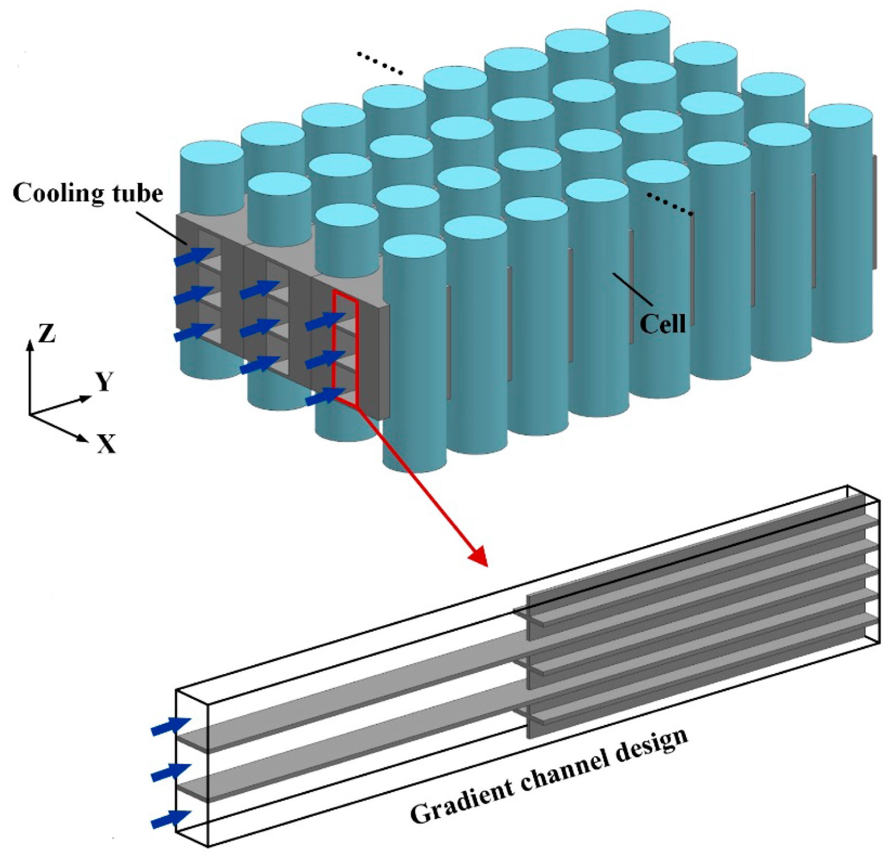
| Gao et al. [48] | Exp-Num | 18650 | 16 | 2 | Water | 360 mL/min | 310.03 | 1.96 | Gradient channel | Flow direction, number of channel segments, segment lengths, inlet flow rate |
| Yates et al. [49] | Num | 18650 | 4 | 5 | Water | 5 × 10⁻⁵ kg/s | 313 | 3.15 | Geometric modification | Channel number, hole diameter, mass flow rate, inlet locations |
| Li et al. [50] | Num | 18650 | 20 | 1–4 | Water | 10−3 kg/s | 303.26 | 1.984 | Geometric modification | Inlet velocity, flow direction, channel cross-section shapes, battery spacing, pressure drop |
| Xia et al. [51] | Num | N.M | 1 | Not mentioned | Water | Not mentioned | 322.95 | 2.38 | Fractal tree-like channels | Pressure drop |
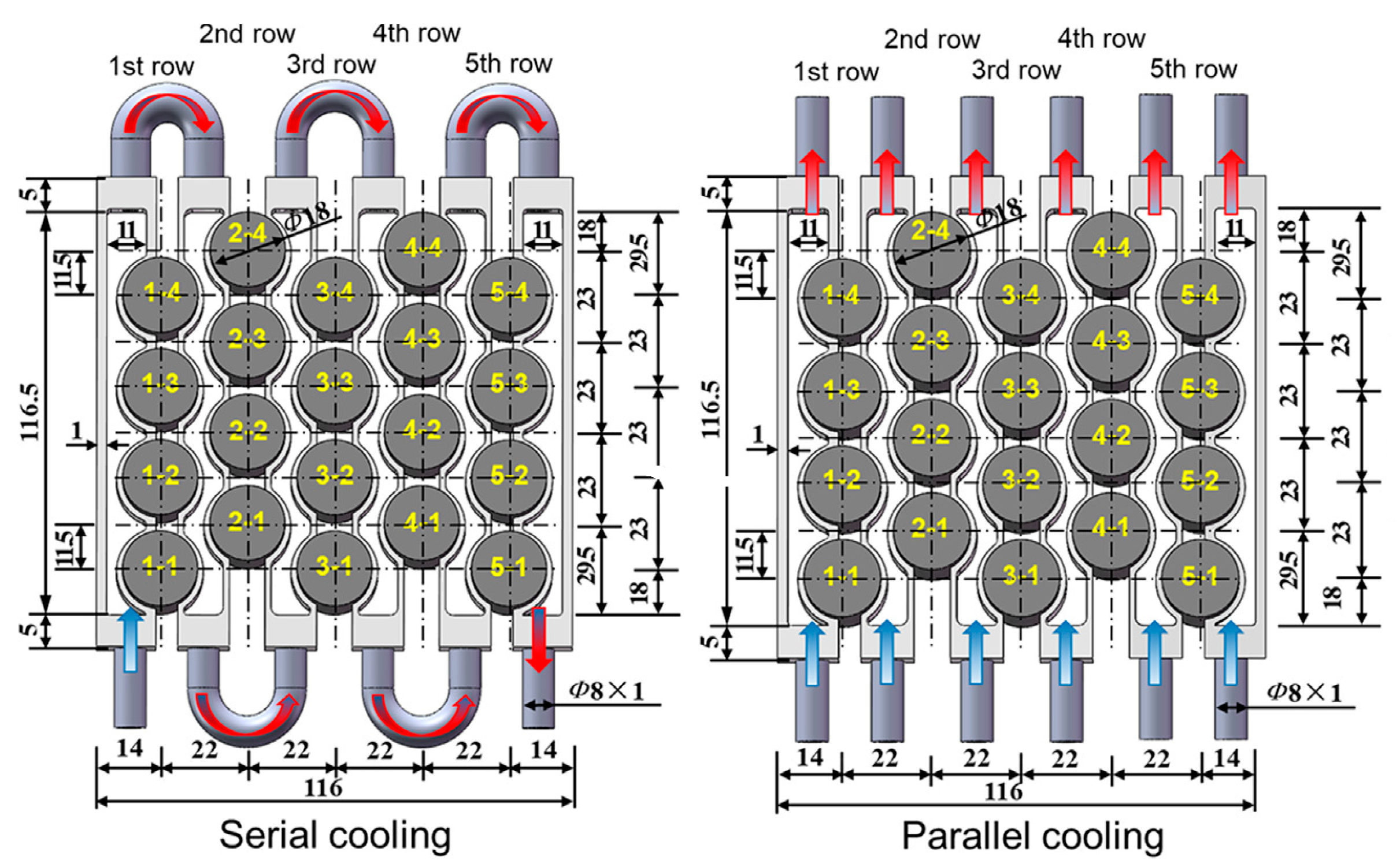
| Wang et al. [52] | Exp-Num | 18650 | 20 | 3 | Water | 80 mL/min | 308.89 | 4.17 | Cooling mode (serial cooling and parallel cooling) | Flow rate, flow direction |
| Kim et al. [53] | Exp-Num | 18650 | 36 | 2–10 | Water | 0.016 kg/s | 323.15 | N.M | Two different types of cold plates | |
| Xie et al. [67] | Num | 18650 | 48 | 2 | Water | 0.2 m/s | 304.01 | 4.99 | Adding baffles | Number, height, and position of baffles |
| Sun et al. [119] | Num | 21700 | 1 | 4 | Water and ethylene glycol | 7.95 × 10⁻² | 306.44 | 1.0605 | Different channel structures | Channel diameter, inlet velocity |
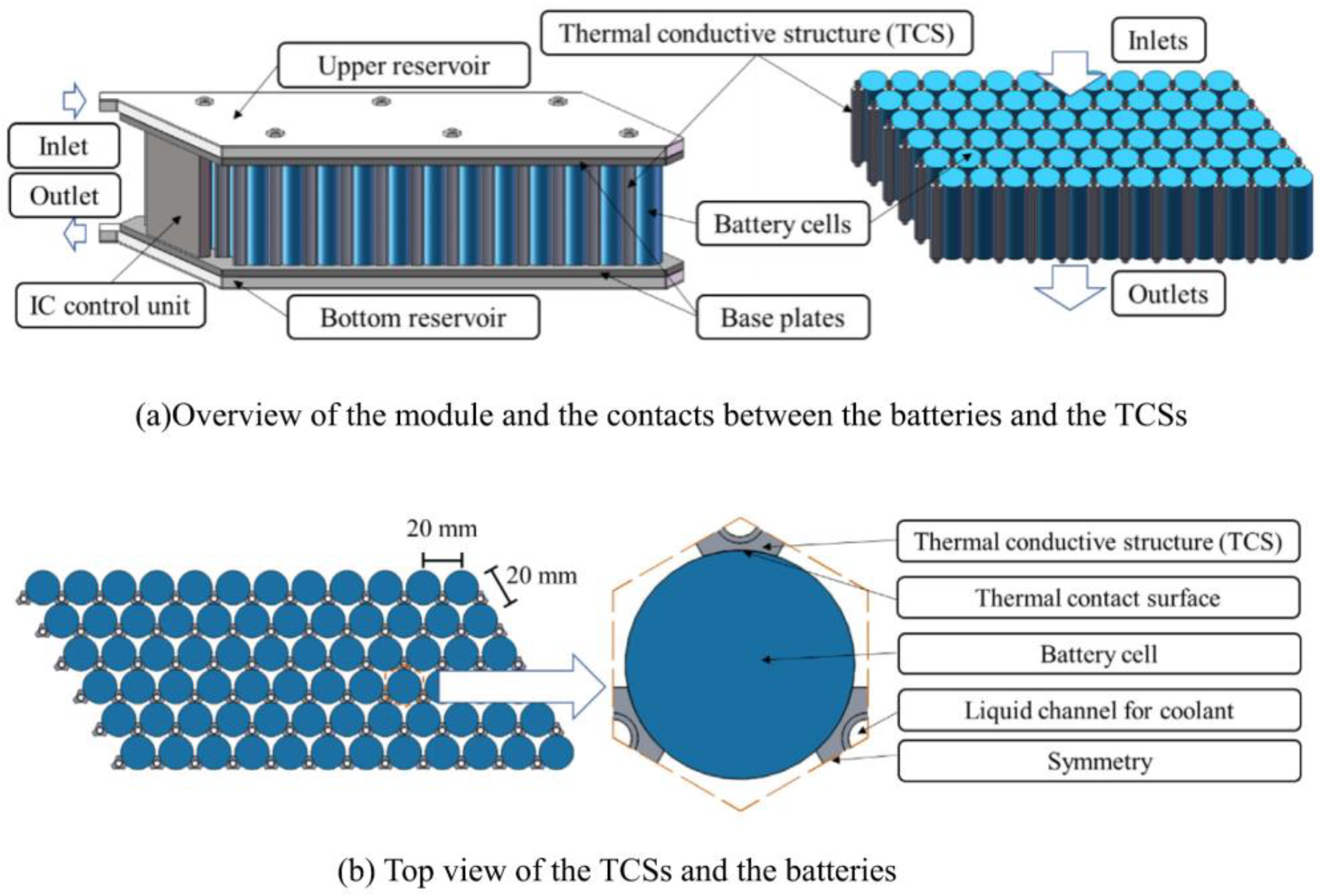
| Sheng et al. [54] | Exp-Num | 21700 | 7 | 1–2 | Water | 10−4 L/s | 309.73 | 1.05 | Cellular liquid cooling jacket | Flow rate, channel dimension |
| Chang et al. [120] | Exp-Num | 18650 | 2 | 0.5 | Water and ethylene glycol | 0.65 L/min | 308.15 | 1.67 | Reciprocating liquid flow | Flow rate, ambient temperature |
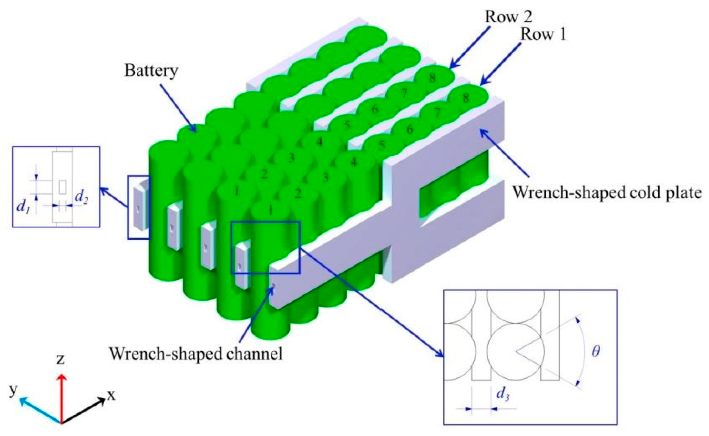
| Xu et al. [55] | Num | 18650 | 32 | 1–3 | Water | 0.1 m/s | 30.3.2 | 3.69 | Wrench-shaped | Bifurcation position, pressure drop |
| Sarchami et al. [63] | Exp-Num | 18650 | 6 | 5 | Alumina nanofluid | 10–120 mL/min | 305.13 | 2.01 | Copper sheath | C-rate, alumina nanoparticle concentration, inflow velocity, stair channel geometry |
| Dong et al. [121] | Num | 18650 | 1 | 5 | Water | 1.94 × 10⁻³ kg/s | 305.51 | 6.98 | Double helix structure | Mass flow rate, helix groove pitch, flow diameter |
| Zhao et al. [99] | Num | 18650 | 71 | 5 | 50% water + 50% methanol | 0.1 m/s | 309.9 | 2.2 | Geometric modification | |
| Xiong et al. [60] | Num | 26650 | 1 | 0.5–2 | Water | 0.4 g/s | 302.972 | 3.858 | Bionic flow channel structure | Channel height, channel length, mass flow rate |
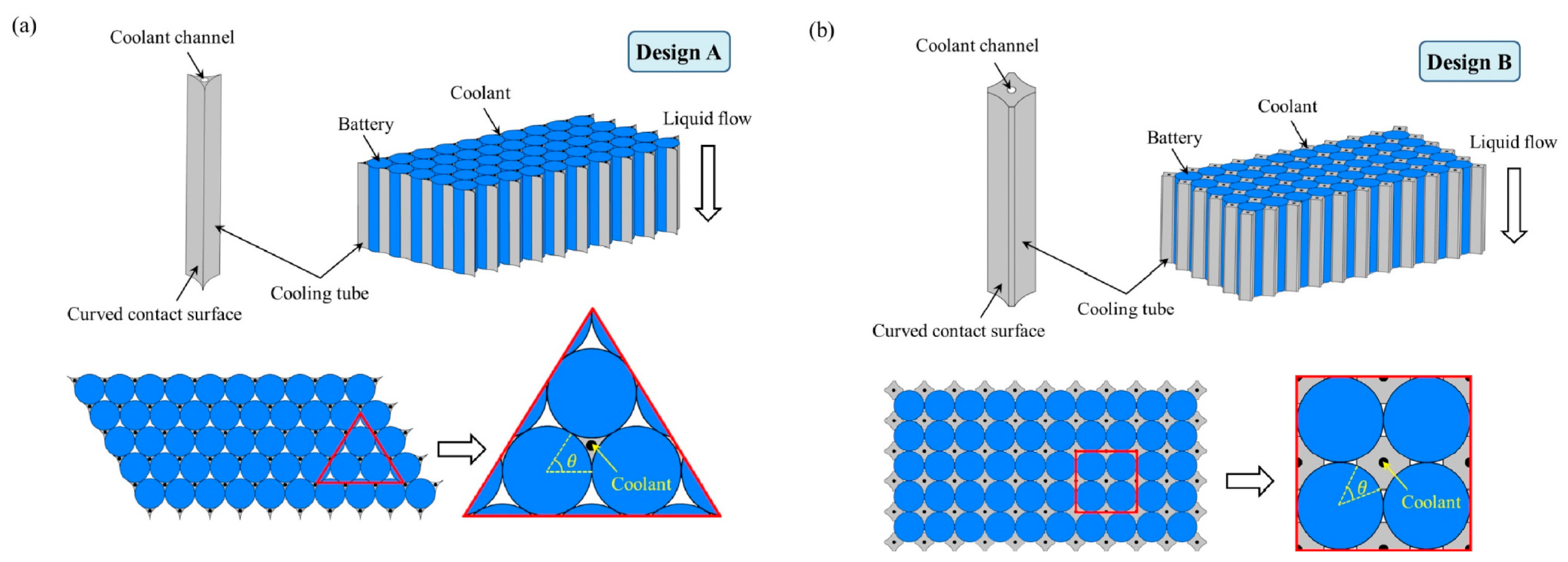
| Shan et al. [59] | Num | 18650 | 10–30 | 2 | Water | 0.02 m/s | 300.47 | 2.09 | Lightweight design | Diameter of the coolant channel, contact surface angle, flow direction layout |
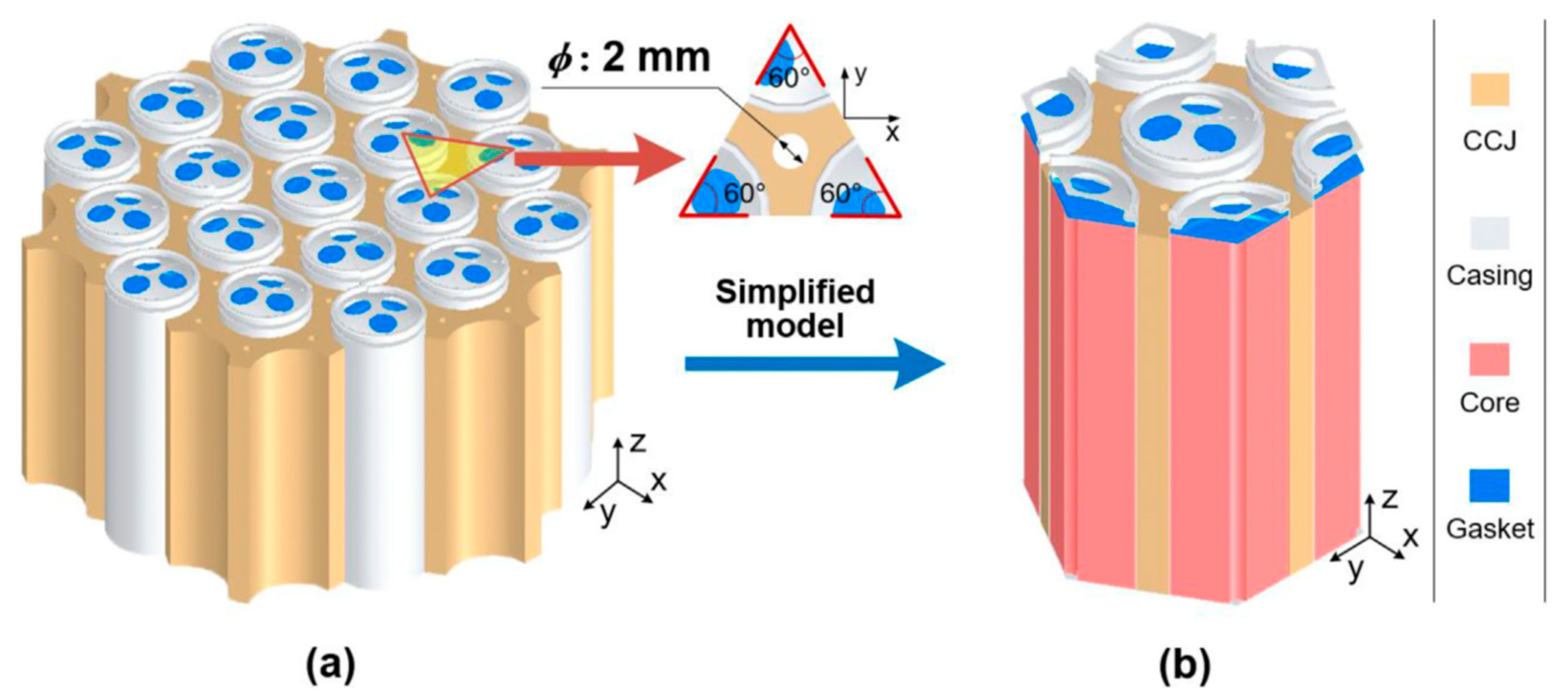
| Liang et al. [61] | Num | 18650 | 5 | 3 | Water | 6 × 10⁻⁷ m3/s | 313.116 | 4.339 | Lightweight design, lower power consumption | Flow rate, inlet water temperature, number of components |
| Tete et al. [57] | Num | 18650 | 25 | 0.5–5 | Water | 0.01 m/s | 301.15 | 0.12 | Cell casings | Discharge rate |
| Tousi et al. [62] | Num | 18650 21700 | 12 | 1–2 | DI-water and AgO nanofluid | 0.2–0.28 m/s | 306.65 | 0.67 | Using nanofluid | Pressure drop, flow rate, nanoparticle volume fraction, discharge C-rate |
| Li et al. [122] | Num | 18650 | 40 | 3 | Water | 0.03–0.3 m/s | 302.4 | 2.88 | Comparing serpentine channel and the U-shaped channel, optimization | Pressure drop |
| Wang et al. [66] | Num | 18650 | 90 | 5 | Water | 0.2–0.5 m/s | 302.15 | 3.3 | Optimization | Inlet velocity, channel number, contact angle |
| Liu et al. [123] | Num | 18650 | 24 | 3, 5 | Water and liquid metal | 0.5 m/s | 311.85 | 3.3 | Liquid metal | Pumping power, flow velocity, structure |
| Yao et al. [124] | Exp-Num | 18650 | 18 | 3 | Water | N.M | 311.75 | 1.9 | Bionic spider web channel | Discharge rates, fluid flow arrangements, Reynolds number |
| Zeng et al. [64] | Exp-Num | 18650 | 32 | 1–6 | Water | 0.5 m/s | 303.83 | 0.739 | Reciprocating flow | Velocity, reciprocating period |
| Zhao et al. [125] | Num | 18650 | 71 | 0.5–5 | Water | 0.5 m/s | 308.15 | 1 | C-rate, flow rate, interfacing area | |
| Esmaeili et al. [126] | Num | 18650 | 16 | 2 | Water | 0.00399 kg/s | 301.4 | 0.78 | Twisted tapes | Twist pitches, twisted tape edges, intensified ratios |
| Zhou et al. [127] | Num | 18650 | 9 | 5 | Water | 3 × 10⁻⁴ kg/s | 303.65 | 4.6 | Half-helical duct | Mass flow rate, pitch and number of ducts, flow direction, duct diameter |
| Rao et al. [128] | Num | 18650 | 24 | 3 | Water | 0.05–0.3 m/s | 302.6 | 2.7 | Contact surface | Block length, inlet velocity |
| Zhao et al. [129] | Num | 42110 | 1 | N.M | Water | 10−3 kg/s | 300 | 1.2 | Geometric modification | Mini-channel quantity, flow rate, flow direction |
| Huang et al. [130] | Exp-Num | 18650 | 48 | 1–5 | Water | 1–8 × 10⁻³ kg/s | 304 | Hysteresis time | Discharge rate, flow rate, heat transfer coefficient | |
| Hasan et al. [131] | Num | 18650 | 52 | N.M | SiO2-water, Al2O3 water, ZnO water, CuO water Nanofluid | 313 | Using nanofluid | Different Reynolds number, pumping power | ||
| Bohacek et al. [132] | Exp-Num | 18650 | 96 | 1 | Water | 0.1–0.7 L/min | 308 | 4.6 | Optimization | Flow rate |
| Ma et al. [65] | Num | 2 | 1 | Water | 0.1–1 m/s | 305 | 2 | Optimization | ||
| Lv et al. [133] | Exp-Num | 21700 | 25 | 1–3 | Water | 0.44 m/s | 310.8 | 4 | Spacing | |
| Liu et al. [56] | Num | 26650 | 25 | 1.3 | Water | 0.025–0.4 m/s | 308.1 | 2.25 | Geometric modification | Flow velocity, tube diameter |
| An et al. [134] | Exp | 18650 | 8 | 1.4 | Water | 0.05–0.35 | 308.15 | 0.7 | Increasing contact surface | High-temperature environment, SOC of the battery module |
| Reference | Method | Type | Number | Load | PCM Composite | Melting Point (K) | Thermal Conductivity (W/(m·K)) | Tmax (K) | ∆T (K) | Main Focus |
|---|---|---|---|---|---|---|---|---|---|---|
| Idi et al. [76] | Exp-Num | 18650 | 1 | 1–4.5 | Paraffin aluminum foam | 300.15–331.15 | 0.15–0.2 | 300 | 1.5 | |
| Lamrani et al. [135] | Num | 21700 | 24 | 3 | RT-31, RT-35 HC, A-32H | 300–309 | 0.2–0.22 | 305 | 3 | |
| Kermani et al. [78] | Num | 18650 | 15 | 2–10 | Chloride hexahydrate (CaCl2·6H2O) and paraffin wax | 302–309 | 0.18–1.008 | 303 | 2 | Optimization, thermophysical properties of the PCM, rate of charge/discharge |
| Zhou et al. [75] | Num | 18650 | 1 | 2 | n-octadecane | 301.15 | 0.152 | 332.36 | 1.89 | Mechanical vibration frequency, vibration amplitude |
| Karimi et al. [136] | Exp | 18650 | 1 | Paraffin mixture | 312–318 | 0.22 | 309 | 3 | Nanoparticles | |
| Lv et al. [137] | Exp | 18650 | 24 | 1, 2.5, 3.5 | Paraffin, expandable graphite, low-density polyethylene | 317–323 | 0.16–0.38 | 321 | 3.9 | |
| Khaboshan et al. [70] | Num | 18650 | 1 | 3 | n-eicosane PCM and metal foam | 309.55 | 0.423 | 310.6 | Fin shapes | |
| Chen et al. [72] | Num | 18650 | 1 | 0.5–1.7 | Paraffin with alkane chain | 0.358 | 315 | Number of fins | ||
| Bias et al. [138] | Exp-Num | 18650 | 1 | 3 | Paraffin with alkane | 314.9 | 1.5 | |||
| Mansir et al. [73] | Num | 18650 | 3 | 2.4 | Paraffin | 0.358 | Fin arrangement | |||
| Liu et al. [139] | Num | 18650 | 1 | 1–3 | Paraffin wax | 311.15 | 0.2 | 314 | 1.48 | Ambient temperature, fin shape |
| Qi et al. [74] | Num | 18650 | 1 | 1–4 | Paraffin wax | 325 | Optimization, fin structure | |||
| Li et al. [79] | Num | 18650 | 4 | Expanded graphite (eg)/paraffin (pa) | 317 | 2.9 | Optimization, mass of PCM | |||
| Wang et al. [140] | Num | 18650 | 21 | 302 | 311 | |||||
| Sun et al. [71] | Num | 18650 | 1 | Paraffin wax | 313–317 | 0.2 | Fin structure |
| Reference | Method | Type | Number | Load | Cooling Method | Flow Regime | Tmax (K) | ∆T (K) | Main Focus | |
|---|---|---|---|---|---|---|---|---|---|---|
| Yang et al. [83] | Exp-Num | 18650 | 18 | 2–4 | Liquid cooling | PCM | Laminar | 312 | 3.5 | Structure parameters, working parameters, and conditions |
| Zhou et al. [81] | Exp-Num | 18650 | 1 | 4 | Liquid cooling | Air cooling | Turbulent | 303 | 2 | Different schemes, inlet velocity, contact resistance |
| Xin et al. [82] | Exp-Num | 18650 | 32 | 3 | Liquid cooling | Air cooling | Laminar | 303.9 | 0.58 | Heat-conducting blocks, mass flow rate |
| Angani et al. [80] | Exp-Num | 21700 | 54 | 1, 1.25 | Liquid cooling | Air cooling | Laminar | 305 | 1.4 | Structure parameters, airflow |
| Wang et al. [141] | Num | 18650 | 48 | Liquid cooling | Gas cooling | Turbulent | 316.5 | Airflow, turbulence intensity | ||
| Chen et al. [142] | Exp-Num | 18650 | 24 | 4 | Liquid cooling | PCM | Laminar | 319.7 | 2.9 | Mass flow rate |
| Behi et al. [143] | Exp-Num | 18650 | 24 | 1.5 | Heat pipe | Air cooling | Laminar | 310.2 | ||
| Kong et al. [144] | Exp-Num | 21700 | 6 | 3 | Liquid cooling | PCM | Laminar | 307 | Cell-to-cell spacing, channel number, coolant velocity | |
| Jiang et al. [145] | Num | 9 | Liquid cooling | PCM | 308 | |||||
| Khan et al. [146] | Num | 18650 | 1 | 3 | Air cooling | PCM | Laminar | 303 | Heat transfer coefficient, melting PCM content | |
| Jilte et al. [147] | Num | 18650 | 1 | 5 | Liquid cooling | PCM | 307.53 | Nanoparticle concentration, structure parameters, melting behavior | ||
| Almehmadi et al. [148] | Num | 18650 | 1 | Air cooling | PCM | Laminar | 304 | Flow rate, PCM location | ||
| Zeng et al. [88] | Exp-Num | 18650 | 9 | 1.3 | Liquid cooling | Heat pipe | 314.18 | 2.16 | Optimization, design parameters | |
| Mashayekhi et al. [149] | Exp-Num | 18650 | 1 | 1–4 | Liquid cooling | PCM | 308 | 0.9 | Nanofluid, power consumption, flow rate | |
| Tian et al. [150] | Num | 18650 | 9 | Air cooling | PCM | 303 | Cost of electricity consumption | |||
| Gholami Zadeh et al. [151] | Num | 18650 | 12 | 5 | Liquid cooling | PCM | 318.1 | 3.60 | Aging analysis | |
| Shahid et al. [152] | Exp-Num | 18650 | 9 | 1–7 | Liquid cooling | PCM | Laminar | 302.5 | 1.8 | |
| Wang et al. [153] | Exp | 18650 | 40 | 2 | Heat pipe | PCM | 320.8 | 2.5 | ||
| Zhao et al. [154] | Exp | 18650 | 12 | 5 | Heat pipe | PCM | 320 | 5 | ||
| Weng et al. [155] | Exp-Num | 18650 | 1 | 1–4 | Air cooling | PCM | 303.6 | 1.6 | ||
| Faizan et al. [156] | Exp-Num | 18650 | 1 | 0.2–2 | Liquid cooling | PCM | Laminar | 307 | 1.6 | |
| Cao et al. [86] | Exp-Num | 18650 | 20 | 3 | Liquid cooling | PCM | Laminar | 315 | 1.2 | Mass fraction of PCMs |
| Chavan et al. [157] | Exp-Num | 18650 | 4 | 1 | Liquid cooling | Heat pipe | 311.4 | |||
| An et al. [87] | Num | 18650 | 25 | 3 | Air cooling | PCM | Laminar | 319.4 | 2 | Mass fraction of PCM, channel layout |
| Peng et al. [89] | Num | 18650 | 4 | 0.5–2 | Heat pipe | PCM | 308 | 1 | PCM properties | |
| Zhao et al. [158] | Exp-Num | 18650 | 40 | 0.96–1.92 | Air cooling | PCM | Turbulent | 312.53 | 4.70 | Optimization, PCM properties |
| Li et al. [159] | Exp-Num | 18650 | 40 | 2–4 | Liquid cooling | Air cooling | Turbulent | 314 | 2 | Optimization, flow direction |
| Bamdezh et al. [160] | Num | 18650 | 1 | 3 | Liquid cooling | PCM | Laminar | 304 | 2.7 | |
| Jiang et al. [161] | Num | 18650 | 9 | 1 | Liquid cooling | PCM | Laminar | 322 | Nanoparticles | |
| Qi et al. [162] | Num | 18650 | 9 | Air cooling | PCM | Laminar | 305 | |||
| Lee et al. [163] | Num | 18650 | 1 | Air cooling | PCM | 303 | ||||
| Akkurt et al. [164] | Num | 21700 | 3 | 3–4 | Air cooling | PCM | Laminar | 304 | ||
| Xin et al. [85] | Num | 18650 | 25 | 5 | Liquid cooling | PCM | Laminar | 318.4 | 3.49 | PCM properties |
| Al-Rashed [84] | Num | 9 | Liquid cooling | PCM | Laminar | 312 | Optimization | |||
| Cao et al. [165] | Num | 18650 | 40 | 1–4 | Liquid cooling | PCM | Laminar | 313 | 5 | Delayed cooling |
| Junwei et al. [166] | Exp | 18650 | 15 | 1–6 | Liquid cooling | PCM | 310.28 | 3.75 | ||
References
- Ahmed, A.A.; Nazzal, M.A.; Darras, B.M.; Deiab, I.M. Global Warming Potential, Water Footprint, and Energy Demand of Shared Autonomous Electric Vehicles Incorporating Circular Economy Practices. Sustain. Prod. Consum. 2023, 36, 449–462. [Google Scholar] [CrossRef]
- Halkos, G.E.; Gkampoura, E.C. Reviewing Usage, Potentials, and Limitations of Renewable Energy Sources. Energies 2020, 13, 2906. [Google Scholar] [CrossRef]
- Behabtu, H.A.; Messagie, M.; Coosemans, T.; Berecibar, M.; Fante, K.A.; Kebede, A.A.; Van Mierlo, J. A Review of Energy Storage Technologies’ Application Potentials in Renewable Energy Sources Grid Integration. Sustainability 2020, 12, 10511. [Google Scholar] [CrossRef]
- Kebede, A.A.; Kalogiannis, T.; Van Mierlo, J.; Berecibar, M. A Comprehensive Review of Stationary Energy Storage Devices for Large Scale Renewable Energy Sources Grid Integration. Renew. Sustain. Energy Rev. 2022, 159, 112213. [Google Scholar] [CrossRef]
- Chombo, P.V.; Laoonual, Y. A Review of Safety Strategies of a Li-Ion Battery. J. Power Sources 2020, 478, 228649. [Google Scholar] [CrossRef]
- Simon, P.; Gogotsi, Y. Perspectives for Electrochemical Capacitors and Related Devices. Nat. Mater. 2020, 19, 1151–1163. [Google Scholar] [CrossRef]
- Yang, L.; Nik-Ghazali, N.N.; Ali, M.A.H.; Chong, W.T.; Yang, Z.; Liu, H. A Review on Thermal Management in Proton Exchange Membrane Fuel Cells: Temperature Distribution and Control. Renew. Sustain. Energy Rev. 2023, 187, 113737. [Google Scholar] [CrossRef]
- Sun, X.; Zhang, Y.; Zhang, Y.; Wang, L.; Wang, K. Summary of Health-State Estimation of Lithium-Ion Batteries Based on Electrochemical Impedance Spectroscopy. Energies 2023, 16, 5682. [Google Scholar] [CrossRef]
- Zhang, X.; Li, Z.; Luo, L.; Fan, Y.; Du, Z. A Review on Thermal Management of Lithium-Ion Batteries for Electric Vehicles. Energy 2022, 238, 121652. [Google Scholar] [CrossRef]
- Yang, W.; Zhou, F.; Chen, X.; Li, K.; Shen, J. Thermal Performance of Honeycomb-Type Cylindrical Lithium-Ion Battery Pack with Air Distribution Plate and Bionic Heat Sinks. Appl. Therm. Eng. 2023, 218, 119299. [Google Scholar] [CrossRef]
- Mousavi, S.; Zadehkabir, A.; Siavashi, M.; Yang, X. An Improved Hybrid Thermal Management System for Prismatic Li-Ion Batteries Integrated with Mini-Channel and Phase Change Materials. Appl. Energy 2023, 334, 120643. [Google Scholar] [CrossRef]
- Ham, S.H.; Jang, D.S.; Lee, M.; Jang, Y.; Kim, Y. Effective Thermal Management of Pouch-Type Lithium-Ion Batteries Using Tab-Cooling Method Involving Highly Conductive Ceramics. Appl. Therm. Eng. 2023, 220, 119790. [Google Scholar] [CrossRef]
- Liu, C.; Shen, W.; Liu, X.; Chen, Y.; Ding, C.; Huang, Q. Research on Thermal Runaway Process of 18650 Cylindrical Lithium-Ion Batteries with Different Cathodes Using Cone Calorimetry. J. Energy Storage 2023, 64, 107175. [Google Scholar] [CrossRef]
- Kim, E.; Song, J.; Dzakpasu, C.B.; Kim, D.; Lim, J.; Kim, D.; Park, S.; Lee, H.; Kwon, T.S.; Lee, Y.M. Degradation Behavior of 21700 Cylindrical Lithium-Ion Battery Cells during Overdischarge Cycling at Low Temperatures. J. Energy Storage 2023, 72, 108627. [Google Scholar] [CrossRef]
- Sharma, D.K.; Prabhakar, A. A Review on Air Cooled and Air Centric Hybrid Thermal Management Techniques for Li-Ion Battery Packs in Electric Vehicles. J. Energy Storage 2021, 41, 102885. [Google Scholar] [CrossRef]
- Talele, V.; Patil, M.S.; Panchal, S.; Fraser, R.; Fowler, M. Battery Thermal Runaway Propagation Time Delay Strategy Using Phase Change Material Integrated with Pyro Block Lining: Dual Functionality Battery Thermal Design. J. Energy Storage 2023, 65, 107253. [Google Scholar] [CrossRef]
- Liu, X.; Ai, W.; Naylor Marlow, M.; Patel, Y.; Wu, B. The Effect of Cell-to-Cell Variations and Thermal Gradients on the Performance and Degradation of Lithium-Ion Battery Packs. Appl. Energy 2019, 248, 489–499. [Google Scholar] [CrossRef]
- Troxler, Y.; Wu, B.; Marinescu, M.; Yufit, V.; Patel, Y.; Marquis, A.J.; Brandon, N.P.; Offer, G.J. The Effect of Thermal Gradients on the Performance of Lithium-Ion Batteries. J. Power Sources 2014, 247, 1018–1025. [Google Scholar] [CrossRef]
- Song, Z.; Yang, N.; Lin, X.; Pinto Delgado, F.; Hofmann, H.; Sun, J. Progression of Cell-to-Cell Variation within Battery Modules under Different Cooling Structures. Appl. Energy 2022, 312, 118836. [Google Scholar] [CrossRef]
- Raijmakers, L.H.J.; Danilov, D.L.; Eichel, R.A.; Notten, P.H.L. A Review on Various Temperature-Indication Methods for Li-Ion Batteries. Appl. Energy 2019, 240, 918–945. [Google Scholar] [CrossRef]
- Jinasena, A.; Spitthoff, L.; Wahl, M.S.; Lamb, J.J.; Shearing, P.R.; Strømman, A.H.; Burheim, O.S. Online Internal Temperature Sensors in Lithium-Ion Batteries: State-of-the-Art and Future Trends. Front. Chem. Eng. 2022, 4, 804704. [Google Scholar] [CrossRef]
- Zheng, Y.; Che, Y.; Hu, X.; Sui, X.; Stroe, D.I.; Teodorescu, R. Thermal State Monitoring of Lithium-Ion Batteries: Progress, Challenges, and Opportunities. Prog. Energy Combust. Sci. 2024, 100, 101120. [Google Scholar] [CrossRef]
- Zhang, J.; Wu, B.; Li, Z.; Huang, J. Simultaneous Estimation of Thermal Parameters for Large-Format Laminated Lithium-Ion Batteries. J. Power Sources 2014, 259, 106–116. [Google Scholar] [CrossRef]
- Drake, S.J.; Wetz, D.A.; Ostanek, J.K.; Miller, S.P.; Heinzel, J.M.; Jain, A. Measurement of Anisotropic Thermophysical Properties of Cylindrical Li-Ion Cells. J. Power Sources 2014, 252, 298–304. [Google Scholar] [CrossRef]
- Zeng, Y.; Chalise, D.; Lubner, S.D.; Kaur, S.; Prasher, R.S. A Review of Thermal Physics and Management inside Lithium-Ion Batteries for High Energy Density and Fast Charging. Energy Storage Mater. 2021, 41, 264–288. [Google Scholar] [CrossRef]
- Kumar, R.; Goel, V. A Study on Thermal Management System of Lithium-Ion Batteries for Electrical Vehicles: A Critical Review. J. Energy Storage 2023, 71, 108025. [Google Scholar] [CrossRef]
- Gan, Y.; Wang, J.; Liang, J.; Huang, Z.; Hu, M. Development of Thermal Equivalent Circuit Model of Heat Pipe-Based Thermal Management System for a Battery Module with Cylindrical Cells. Appl. Therm. Eng. 2020, 164, 114523. [Google Scholar] [CrossRef]
- Feng, L.; Zhou, S.; Li, Y.; Wang, Y.; Zhao, Q.; Luo, C.; Wang, G.; Yan, K. Experimental Investigation of Thermal and Strain Management for Lithium-Ion Battery Pack in Heat Pipe Cooling. J. Energy Storage 2018, 16, 84–92. [Google Scholar] [CrossRef]
- Liu, W.; Jia, Z.; Luo, Y.; Xie, W.; Deng, T. Experimental Investigation on Thermal Management of Cylindrical Li-Ion Battery Pack Based on Vapor Chamber Combined with Fin Structure. Appl. Therm. Eng. 2019, 162, 114272. [Google Scholar] [CrossRef]
- Alihosseini, A.; Shafaee, M. Experimental Study and Numerical Simulation of a Lithium-Ion Battery Thermal Management System Using a Heat Pipe. J. Energy Storage 2021, 39, 102616. [Google Scholar] [CrossRef]
- Wang, J.; Gan, Y.; Liang, J.; Tan, M.; Li, Y. Sensitivity Analysis of Factors Influencing a Heat Pipe-Based Thermal Management System for a Battery Module with Cylindrical Cells. Appl. Therm. Eng. 2019, 151, 475–485. [Google Scholar] [CrossRef]
- Li, Y.; Bai, M.; Zhou, Z.; Lv, J.; Hu, C.; Gao, L.; Peng, C.; Li, Y.; Li, Y.; Song, Y. Experimental Study of Liquid Immersion Cooling for Different Cylindrical Lithium-Ion Batteries under Rapid Charging Conditions. Therm. Sci. Eng. Prog. 2023, 37, 101569. [Google Scholar] [CrossRef]
- Liu, Y.; Aldan, G.; Huang, X.; Hao, M. Single-Phase Static Immersion Cooling for Cylindrical Lithium-Ion Battery Module. Appl. Therm. Eng. 2023, 233, 121184. [Google Scholar] [CrossRef]
- Song, W.; Bai, F.; Chen, M.; Lin, S.; Feng, Z.; Li, Y. Thermal Management of Standby Battery for Outdoor Base Station Based on the Semiconductor Thermoelectric Device and Phase Change Materials. Appl. Therm. Eng. 2018, 137, 203–217. [Google Scholar] [CrossRef]
- Yang, W.; Zhou, F.; Zhou, H.; Liu, Y. Thermal Performance of Axial Air Cooling System with Bionic Surface Structure for Cylindrical Lithium-Ion Battery Module. Int. J. Heat Mass Transf. 2020, 161, 120307. [Google Scholar] [CrossRef]
- Zhou, H.; Zhou, F.; Xu, L.; Kong, J.; Yang, Q. Thermal Performance of Cylindrical Lithium-Ion Battery Thermal Management System Based on Air Distribution Pipe. Int. J. Heat Mass Transf. 2019, 131, 984–998. [Google Scholar] [CrossRef]
- Wang, T.; Tseng, K.J.; Zhao, J.; Wei, Z. Thermal Investigation of Lithium-Ion Battery Module with Different Cell Arrangement Structures and Forced Air-Cooling Strategies. Appl. Energy 2014, 134, 229–238. [Google Scholar] [CrossRef]
- Kummitha, O.R. Thermal Cooling of Li-Ion Cylindrical Cells Battery Module with Baffles Arrangement for Airflow Cooling Numerical Analysis. J. Energy Storage 2023, 59, 106474. [Google Scholar] [CrossRef]
- Lu, Z.; Yu, X.; Wei, L.; Qiu, Y.; Zhang, L.; Meng, X.; Jin, L. Parametric Study of Forced Air Cooling Strategy for Lithium-Ion Battery Pack with Staggered Arrangement. Appl. Therm. Eng. 2018, 136, 28–40. [Google Scholar] [CrossRef]
- Ji, C.; Wang, B.; Wang, S.; Pan, S.; Wang, D.; Qi, P.; Zhang, K. Optimization on Uniformity of Lithium-Ion Cylindrical Battery Module by Different Arrangement Strategy. Appl. Therm. Eng. 2019, 157, 113683. [Google Scholar] [CrossRef]
- Koorata, P.K.; Chandrasekaran, N. Numerical Investigation of Cooling Performance of a Novel Air-Cooled Thermal Management System for Cylindrical Li-Ion Battery Module. Appl. Therm. Eng. 2021, 193, 116961. [Google Scholar] [CrossRef]
- Lee, N.; Choi, J.; Lee, J.; Shin, D.; Um, S. Prognostic Analysis of Thermal Interface Material Effects on Anisotropic Heat Transfer Characteristics and State of Health of a 21700 Cylindrical Lithium-Ion Battery Module. J. Energy Storage 2023, 72, 108594. [Google Scholar] [CrossRef]
- Mahamud, R.; Park, C. Reciprocating Air Flow for Li-Ion Battery Thermal Management to Improve Temperature Uniformity. J. Power Sources 2011, 196, 5685–5696. [Google Scholar] [CrossRef]
- Wang, Y.; Liu, B.; Han, P.; Hao, C.; Li, S.; You, Z.; Wang, M. Optimization of an Air-Based Thermal Management System for Lithium-Ion Battery Packs. J. Energy Storage 2021, 44, 103314. [Google Scholar] [CrossRef]
- Jaliliantabar, F.; Mamat, R.; Kumarasamy, S. Prediction of Lithium-Ion Battery Temperature in Different Operating Conditions Equipped with Passive Battery Thermal Management System by Artificial Neural Networks. Mater. Today Proc. 2022, 48, 1796–1804. [Google Scholar] [CrossRef]
- Li, A.; Yuen, A.C.Y.; Wang, W.; Chen, T.B.Y.; Lai, C.S.; Yang, W.; Wu, W.; Chan, Q.N.; Kook, S.; Yeoh, G.H. Integration of Computational Fluid Dynamics and Artificial Neural Network for Optimization Design of Battery Thermal Management System. Batteries 2022, 8, 69. [Google Scholar] [CrossRef]
- Wang, Y.; Chen, X.; Li, C.; Yu, Y.; Zhou, G.; Wang, C.Y.; Zhao, W. Temperature Prediction of Lithium-Ion Battery Based on Artificial Neural Network Model. Appl. Therm. Eng. 2023, 228, 120482. [Google Scholar] [CrossRef]
- Gao, R.; Fan, Z.; Liu, S. A Gradient Channel-Based Novel Design of Liquid-Cooled Battery Thermal Management System for Thermal Uniformity Improvement. J. Energy Storage 2022, 48, 104014. [Google Scholar] [CrossRef]
- Yates, M.; Akrami, M.; Javadi, A.A. Analysing the Performance of Liquid Cooling Designs in Cylindrical Lithium-Ion Batteries. J. Energy Storage 2021, 33, 100913. [Google Scholar] [CrossRef]
- Li, W.; Garg, A.; Wang, N.; Gao, L.; Le Phung, M.L.; Tran, V.M. Computational Fluid Dynamics-Based Numerical Analysis for Studying the Effect of Mini-Channel Cooling Plate, Flow Characteristics, and Battery Arrangement for Cylindrical Lithium-Ion Battery Pack. J. Electrochem. Energy Convers. Storage 2022, 19, 041003. [Google Scholar] [CrossRef]
- Xia, C.; Fu, J.; Lai, J.; Yao, X.; Chen, Z. Conjugate Heat Transfer in Fractal Tree-like Channels Network Heat Sink for High-Speed Motorized Spindle Cooling. Appl. Therm. Eng. 2015, 90, 1032–1042. [Google Scholar] [CrossRef]
- Wang, H.; Tao, T.; Xu, J.; Mei, X.; Liu, X.; Gou, P. Cooling Capacity of a Novel Modular Liquid-Cooled Battery Thermal Management System for Cylindrical Lithium Ion Batteries. Appl. Therm. Eng. 2020, 178, 115591. [Google Scholar] [CrossRef]
- Kim, B.R.; Nguyen, T.N.; Park, C.W. Cooling Performance of Thermal Management System for Lithium-Ion Batteries Using Two Types of Cold Plate: Experiment and MATLAB/Simulink-Simscape Simulation. Int. Commun. Heat Mass Transf. 2023, 145, 106816. [Google Scholar] [CrossRef]
- Sheng, L.; Zhang, H.; Su, L.; Zhang, Z.; Zhang, H.; Li, K.; Fang, Y.; Ye, W. Effect Analysis on Thermal Profile Management of a Cylindrical Lithium-Ion Battery Utilizing a Cellular Liquid Cooling Jacket. Energy 2021, 220, 119725. [Google Scholar] [CrossRef]
- Xu, Q.; Xie, Y.; Huang, Y.; Li, X.; Huang, H.; Bei, S.; Wang, H.; Zheng, K.; Wang, X.; Li, L. Enhancement of Thermal Management for Cylindrical Battery Module Based on a Novel Wrench-Shaped Design for the Cold Plate. Sustain. Energy Technol. Assess. 2023, 59, 103421. [Google Scholar] [CrossRef]
- Liu, Z.; Liu, X.; Meng, H.; Guo, L.; Zhang, Z. Numerical Analysis of the Thermal Performance of a Liquid Cooling Battery Module Based on the Gradient Ratio Flow Velocity and Gradient Increment Tube Diameter. Int. J. Heat Mass Transf. 2021, 175, 121338. [Google Scholar] [CrossRef]
- Tete, P.R.; Gupta, M.M.; Joshi, S.S. Numerical Investigation on Thermal Characteristics of a Liquid-Cooled Lithium-Ion Battery Pack with Cylindrical Cell Casings and a Square Duct. J. Energy Storage 2022, 48, 104041. [Google Scholar] [CrossRef]
- Lai, Y.; Wu, W.; Chen, K.; Wang, S.; Xin, C. A Compact and Lightweight Liquid-Cooled Thermal Management Solution for Cylindrical Lithium-Ion Power Battery Pack. Int. J. Heat Mass Transf. 2019, 144, 118581. [Google Scholar] [CrossRef]
- Shan, S.; Li, L.; Xu, Q.; Ling, L.; Xie, Y.; Wang, H.; Zheng, K.; Zhang, L.; Bei, S. Numerical Investigation of a Compact and Lightweight Thermal Management System with Axially Mounted Cooling Tubes for Cylindrical Lithium-Ion Battery Module. Energy 2023, 274, 127410. [Google Scholar] [CrossRef]
- Xiong, X.; Wang, Z.; Fan, Y.; Wang, H. Numerical Analysis of Cylindrical Lithium-Ion Battery Thermal Management System Based on Bionic Flow Channel Structure. Therm. Sci. Eng. Prog. 2023, 42, 101879. [Google Scholar] [CrossRef]
- Liang, G.; Li, J.; He, J.; Tian, J.; Chen, X.; Chen, L. Numerical Investigation on a Unitization-Based Thermal Management for Cylindrical Lithium-Ion Batteries. Energy Rep. 2022, 8, 4608–4621. [Google Scholar] [CrossRef]
- Tousi, M.; Sarchami, A.; Kiani, M.; Najafi, M.; Houshfar, E. Numerical Study of Novel Liquid-Cooled Thermal Management System for Cylindrical Li-Ion Battery Packs under High Discharge Rate Based on AgO Nanofluid and Copper Sheath. J. Energy Storage 2021, 41, 102910. [Google Scholar] [CrossRef]
- Sarchami, A.; Najafi, M.; Imam, A.; Houshfar, E. Experimental Study of Thermal Management System for Cylindrical Li-Ion Battery Pack Based on Nanofluid Cooling and Copper Sheath. Int. J. Therm. Sci. 2021, 171, 107244. [Google Scholar] [CrossRef]
- Zeng, W.; Ma, C.; Hu, S.; Li, S.; Zhang, Y. The Performance Investigation and Optimization of Reciprocating Flow Applied for Liquid-Cooling-Based Battery Thermal Management System. Energy Convers. Manag. 2023, 292, 117378. [Google Scholar] [CrossRef]
- Ma, Y.; Mou, H.; Zhao, H. Cooling Optimization Strategy for Lithium-Ion Batteries Based on Triple-Step Nonlinear Method. Energy 2020, 201, 117678. [Google Scholar] [CrossRef]
- Wang, Y.; Zhang, G.; Yang, X. Optimization of Liquid Cooling Technology for Cylindrical Power Battery Module. Appl. Therm. Eng. 2019, 162, 114200. [Google Scholar] [CrossRef]
- Xie, L.; Huang, Y.; Lai, H. Coupled Prediction Model of Liquid-Cooling Based Thermal Management System for Cylindrical Lithium-Ion Module. Appl. Therm. Eng. 2020, 178, 115599. [Google Scholar] [CrossRef]
- Talele, V.; Patil, M.S.; Panchal, S.; Fraser, R.; Fowler, M.; Gunti, S.R. Novel Metallic Separator Coupled Composite Phase Change Material Passive Thermal Design for Large Format Prismatic Battery Pack. J. Energy Storage 2023, 58, 106336. [Google Scholar] [CrossRef]
- Talele, V.; Zhao, P. Effect of Nano-Enhanced Phase Change Material on the Thermal Management of a 18650 NMC Battery Pack. J. Energy Storage 2023, 64, 107068. [Google Scholar] [CrossRef]
- Najafi Khaboshan, H.; Jaliliantabar, F.; Adam Abdullah, A.; Panchal, S. Improving the Cooling Performance of Cylindrical Lithium-Ion Battery Using Three Passive Methods in a Battery Thermal Management System. Appl. Therm. Eng. 2023, 227, 120320. [Google Scholar] [CrossRef]
- Sun, Z.; Fan, R.; Yan, F.; Zhou, T.; Zheng, N. Thermal Management of the Lithium-Ion Battery by the Composite PCM-Fin Structures. Int. J. Heat Mass Transf. 2019, 145, 118739. [Google Scholar] [CrossRef]
- Chen, H.; Abidi, A.; Hussein, A.K.; Younis, O.; Degani, M.; Heidarshenas, B. Investigation of the Use of Extended Surfaces in Paraffin Wax Phase Change Material in Thermal Management of a Cylindrical Lithium-Ion Battery: Applicable in the Aerospace Industry. J. Energy Storage 2022, 45, 103685. [Google Scholar] [CrossRef]
- Mansir, I.B.; Sinaga, N.; Farouk, N.; Aljaghtham, M.; Diyoke, C.; Nguyen, D.D. Numerical Simulation of Dimensions and Arrangement of Triangular Fins Mounted on Cylindrical Lithium-Ion Batteries in Passive Thermal Management. J. Energy Storage 2022, 50, 104392. [Google Scholar] [CrossRef]
- Qi, X.; Sidi, M.O.; Tlili, I.; Ibrahim, T.K.; Elkotb, M.A.; El-Shorbagy, M.A.; Li, Z. Optimization and Sensitivity Analysis of Extended Surfaces during Melting and Freezing of Phase Changing Materials in Cylindrical Lithium-Ion Battery Cooling. J. Energy Storage 2022, 51, 104545. [Google Scholar] [CrossRef]
- Zhou, Z.; Chen, S.; Luo, M.; Du, W.; Wu, Y.; Yu, Y. Effect of Mechanical Vibration on Phase Change Material Based Thermal Management System for a Cylindrical Lithium-Ion Battery at High Ambient Temperature and High Discharge Rate. Int. J. Heat Mass Transf. 2023, 211, 124255. [Google Scholar] [CrossRef]
- El Idi, M.M.; Karkri, M.; Abdou Tankari, M. A Passive Thermal Management System of Li-Ion Batteries Using PCM Composites: Experimental and Numerical Investigations. Int. J. Heat Mass Transf. 2021, 169, 120894. [Google Scholar] [CrossRef]
- Sazvar, B.; Moqtaderi, H. A Numerical Study on the Capacity Improvement of Cylindrical Battery Cooling Systems Using Nano-Enhanced Phase Change Material and Axisymmetric Stepped Fins. J. Energy Storage 2023, 62, 106833. [Google Scholar] [CrossRef]
- Ranjbar Kermani, J.; Mahlouji Taheri, M.; Shafii, M.B.; Moosavi, A. Analytical Solution, Optimization and Design of a Phase Change Cooling Pack for Cylindrical Lithium-Ion Batteries. Appl. Therm. Eng. 2023, 232, 120963. [Google Scholar] [CrossRef]
- Li, Y.; Du, Y.; Xu, T.; Wu, H.; Zhou, X.; Ling, Z.; Zhang, Z. Optimization of Thermal Management System for Li-Ion Batteries Using Phase Change Material. Appl. Therm. Eng. 2018, 131, 766–778. [Google Scholar] [CrossRef]
- Angani, A.; Kim, H.W.; Hwang, M.H.; Kim, E.; Kim, K.M.; Cha, H.R. A Comparison between Zig-Zag Plated Hybrid Parallel Pipe and Liquid Cooling Battery Thermal Management Systems for Lithium-Ion Battery Module. Appl. Therm. Eng. 2023, 219, 119599. [Google Scholar] [CrossRef]
- Zhou, H.; Niu, J.; Guo, X.; Xu, L.; Song, Z.; Yin, X. Thermal Performance of a Hybrid Thermal Management System Based on the Half Helical Coil Coupled with Air Jet Cooling for Cylindrical Lithium-Ion Battery. Appl. Therm. Eng. 2023, 225, 120231. [Google Scholar] [CrossRef]
- Xin, S.; Wang, C.; Xi, H. Thermal Management Scheme and Optimization of Cylindrical Lithium-Ion Battery Pack Based on Air Cooling and Liquid Cooling. Appl. Therm. Eng. 2023, 224, 120100. [Google Scholar] [CrossRef]
- Yang, W.; Zhou, F.; Liu, Y.; Xu, S.; Chen, X. Thermal Performance of Honeycomb-like Battery Thermal Management System with Bionic Liquid Mini-Channel and Phase Change Materials for Cylindrical Lithium-Ion Battery. Appl. Therm. Eng. 2021, 188, 116649. [Google Scholar] [CrossRef]
- Al-Rashed, A.A.A.A. Thermal Management of Lithium-Ion Batteries with Simultaneous Use of Hybrid Nanofluid and Nano-Enhanced Phase Change Material: A Numerical Study. J. Energy Storage 2022, 46, 103730. [Google Scholar] [CrossRef]
- Xin, Q.; Xiao, J.; Yang, T.; Zhang, H.; Long, X. Thermal Management of Lithium-Ion Batteries under High Ambient Temperature and Rapid Discharging Using Composite PCM and Liquid Cooling. Appl. Therm. Eng. 2022, 210, 118230. [Google Scholar] [CrossRef]
- Cao, J.; Luo, M.; Fang, X.; Ling, Z.; Zhang, Z. Liquid Cooling with Phase Change Materials for Cylindrical Li-Ion Batteries: An Experimental and Numerical Study. Energy 2020, 191, 116565. [Google Scholar] [CrossRef]
- An, Z.; Chen, X.; Zhao, L.; Gao, Z. Numerical Investigation on Integrated Thermal Management for a Lithium-Ion Battery Module with a Composite Phase Change Material and Liquid Cooling. Appl. Therm. Eng. 2019, 163, 114345. [Google Scholar] [CrossRef]
- Zeng, W.; Niu, Y.; Li, S.; Hu, S.; Mao, B.; Zhang, Y. Cooling Performance and Optimization of a New Hybrid Thermal Management System of Cylindrical Battery. Appl. Therm. Eng. 2022, 217, 119171. [Google Scholar] [CrossRef]
- Peng, P.; Wang, Y.; Jiang, F. Numerical Study of PCM Thermal Behavior of a Novel PCM-Heat Pipe Combined System for Li-Ion Battery Thermal Management. Appl. Therm. Eng. 2022, 209, 118293. [Google Scholar] [CrossRef]
- Zhou, J.; Zhang, S.; Yang, H.; Dong, F. Thermal Performance of a Novel Honeycomb Cooling System for Cylindrical Lithium-Ion Batteries. Heat Transf. Eng. 2023, 1–17. [Google Scholar] [CrossRef]
- Hasan, H.A.; Togun, H.; Abed, A.M.; Biswas, N.; Mohammed, H.I. Thermal Performance Assessment for an Array of Cylindrical Lithium-Ion Battery Cells Using an Air-Cooling System. Appl. Energy 2023, 346, 121354. [Google Scholar] [CrossRef]
- Zhao, J.; Rao, Z.; Huo, Y.; Liu, X.; Li, Y. Thermal Management of Cylindrical Power Battery Module for Extending the Life of New Energy Electric Vehicles. Appl. Therm. Eng. 2015, 85, 33–43. [Google Scholar] [CrossRef]
- Li, X.; He, F.; Ma, L. Thermal Management of Cylindrical Batteries Investigated Using Wind Tunnel Testing and Computational Fluid Dynamics Simulation. J. Power Sources 2013, 238, 395–402. [Google Scholar] [CrossRef]
- Hai, T.; Abidi, A.; Sajadi, S.M.; Zain, J.M.; Malekshah, E.H.; Aybar, H. Simultaneous Cooling of Plate and Cylindrical Batteries in an Air-Cooled Lithium Battery Thermal Management System, by Changing the Distances of the Batteries from Each Other and the Pack Wall. J. Taiwan Inst. Chem. Eng. 2023, 148, 104931. [Google Scholar] [CrossRef]
- Li, S.; Kirkaldy, N.; Zhang, C.; Gopalakrishnan, K.; Amietszajew, T.; Diaz, L.B.; Barreras, J.V.; Shams, M.; Hua, X.; Patel, Y.; et al. Optimal Cell Tab Design and Cooling Strategy for Cylindrical Lithium-Ion Batteries. J. Power Sources 2021, 492, 229594. [Google Scholar] [CrossRef]
- Saechan, P.; Dhuchakallaya, I. Numerical Study on the Air-Cooled Thermal Management of Lithium-Ion Battery Pack for Electrical Vehicles. Energy Rep. 2022, 8, 1264–1270. [Google Scholar] [CrossRef]
- Ruhani, B.; Abidi, A.; Hussein, A.K.; Younis, O.; Degani, M.; Sharifpur, M. Numerical Simulation of the Effect of Battery Distance and Inlet and Outlet Length on the Cooling of Cylindrical Lithium-Ion Batteries and Overall Performance of Thermal Management System. J. Energy Storage 2022, 45, 103714. [Google Scholar] [CrossRef]
- Xun, J.; Liu, R.; Jiao, K. Numerical and Analytical Modeling of Lithium Ion Battery Thermal Behaviors with Different Cooling Designs. J. Power Sources 2013, 233, 47–61. [Google Scholar] [CrossRef]
- Zhao, C.; Sousa, A.C.M.; Jiang, F. Minimization of Thermal Non-Uniformity in Lithium-Ion Battery Pack Cooled by Channeled Liquid Flow. Int. J. Heat Mass Transf. 2019, 129, 660–670. [Google Scholar] [CrossRef]
- Yang, T.; Yang, N.; Zhang, X.; Li, G. Investigation of the Thermal Performance of Axial-Flow Air Cooling for the Lithium-Ion Battery Pack. Int. J. Therm. Sci. 2016, 108, 132–144. [Google Scholar] [CrossRef]
- Fan, Y.; Bao, Y.; Ling, C.; Chu, Y.; Tan, X.; Yang, S. Experimental Study on the Thermal Management Performance of Air Cooling for High Energy Density Cylindrical Lithium-Ion Batteries. Appl. Therm. Eng. 2019, 155, 96–109. [Google Scholar] [CrossRef]
- Cen, J.; Li, Z.; Jiang, F. Experimental Investigation on Using the Electric Vehicle Air Conditioning System for Lithium-Ion Battery Thermal Management. Energy Sustain. Dev. 2018, 45, 88–95. [Google Scholar] [CrossRef]
- Jiaqiang, E.; Yue, M.; Chen, J.; Zhu, H.; Deng, Y.; Zhu, Y.; Zhang, F.; Wen, M.; Zhang, B.; Kang, S. Effects of the Different Air Cooling Strategies on Cooling Performance of a Lithium-Ion Battery Module with Baffle. Appl. Therm. Eng. 2018, 144, 231–241. [Google Scholar] [CrossRef]
- Chen, H.; Abidi, A.; Mohammad Sajadi, S.; Yuan, Y.; Aybar, H.; Heidarshenas, B. Effect of Splitter Damper on Airflow Conduction for Thermal Management of a Lithium-Ion Battery Cooling System with Plate and Cylindrical Batteries. J. Taiwan Inst. Chem. Eng. 2023, 148, 104853. [Google Scholar] [CrossRef]
- Hai, T.; Said, N.M.; Cheraghian, G.; Zhou, J.; Malekshah, E.H.; Sharifpur, M. Effect of Air Inlet and Outlet Cross Sections on the Cooling System of Cylindrical Lithium Battery with Segmental Arrangement Utilized in Electric Vehicles. J. Power Sources 2023, 553, 232222. [Google Scholar] [CrossRef]
- Wang, T.; Tseng, K.J.; Zhao, J. Development of Efficient Air-Cooling Strategies for Lithium-Ion Battery Module Based on Empirical Heat Source Model. Appl. Therm. Eng. 2015, 90, 521–529. [Google Scholar] [CrossRef]
- Shahid, S.; Agelin-Chaab, M. Development and Analysis of a Technique to Improve Air-Cooling and Temperature Uniformity in a Battery Pack for Cylindrical Batteries. Therm. Sci. Eng. Prog. 2018, 5, 351–363. [Google Scholar] [CrossRef]
- Zhang, F.; Wang, P.; Yi, M. Design Optimization of Forced Air-Cooled Lithium-Ion Battery Module Based on Multi-Vents. J. Energy Storage 2021, 40, 102781. [Google Scholar] [CrossRef]
- Hasan, H.A.; Togun, H.; Mohammed, H.I.; Abed, A.M.; Homod, R.Z. CFD Simulation of Effect Spacing between Lithium-Ion Batteries by Using Flow Air inside the Cooling Pack. J. Energy Storage 2023, 72, 108631. [Google Scholar] [CrossRef]
- Yang, N.; Zhang, X.; Li, G.; Hua, D. Assessment of the Forced Air-Cooling Performance for Cylindrical Lithium-Ion Battery Packs: A Comparative Analysis between Aligned and Staggered Cell Arrangements. Appl. Therm. Eng. 2015, 80, 55–65. [Google Scholar] [CrossRef]
- Shahid, S.; Agelin-Chaab, M. Analysis of Cooling Effectiveness and Temperature Uniformity in a Battery Pack for Cylindrical Batteries. Energies 2017, 10, 1157. [Google Scholar] [CrossRef]
- Peng, X.; Cui, X.; Liao, X.; Garg, A. A Thermal Investigation and Optimization of an Air-Cooled Lithium-Ion Battery Pack. Energies 2020, 13, 2956. [Google Scholar] [CrossRef]
- Hai, T.; Abidi, A.; Abed, A.M.; Zhou, J.; Malekshah, E.H.; Aybar, H. Three-Dimensional Numerical Study of the Effect of an Air-Cooled System on Thermal Management of a Cylindrical Lithium-Ion Battery Pack with Two Different Arrangements of Battery Cells. J. Power Sources 2022, 550, 232117. [Google Scholar] [CrossRef]
- Reyes-Marambio, J.; Moser, F.; Gana, F.; Severino, B.; Calderón-Muñoz, W.R.; Palma-Behnke, R.; Estevez, P.A.; Orchard, M.; Cortés, M. A Fractal Time Thermal Model for Predicting the Surface Temperature of Air-Cooled Cylindrical Li-Ion Cells Based on Experimental Measurements. J. Power Sources 2016, 306, 636–645. [Google Scholar] [CrossRef]
- Qin, P.; Liao, M.; Mei, W.; Sun, J.; Wang, Q. The Experimental and Numerical Investigation on a Hybrid Battery Thermal Management System Based on Forced-Air Convection and Internal Finned Structure. Appl. Therm. Eng. 2021, 195, 117212. [Google Scholar] [CrossRef]
- Saw, L.H.; Ye, Y.; Tay, A.A.O.; Chong, W.T.; Kuan, S.H.; Yew, M.C. Computational Fluid Dynamic and Thermal Analysis of Lithium-Ion Battery Pack with Air Cooling. Appl. Energy 2016, 177, 783–792. [Google Scholar] [CrossRef]
- Yu, X.; Lu, Z.; Zhang, L.; Wei, L.; Cui, X.; Jin, L. Experimental Study on Transient Thermal Characteristics of Stagger-Arranged Lithium-Ion Battery Pack with Air Cooling Strategy. Int. J. Heat Mass Transf. 2019, 143, 118576. [Google Scholar] [CrossRef]
- Wang, Y.W.; Jiang, J.M.; Chung, Y.H.; Chen, W.C.; Shu, C.M. Forced-Air Cooling System for Large-Scale Lithium-Ion Battery Modules during Charge and Discharge Processes. J. Therm. Anal. Calorim. 2019, 135, 2891–2901. [Google Scholar] [CrossRef]
- Sun, Y.; Bai, R.; Ma, J. Development and Analysis of a New Cylindrical Lithium-Ion Battery Thermal Management System. Chin. J. Mech. Eng. 2022, 35, 1–15. [Google Scholar] [CrossRef]
- Chang, G.; Cui, X.; Li, Y.; Ji, Y. Effects of Reciprocating Liquid Flow Battery Thermal Management System on Thermal Characteristics and Uniformity of Large Lithium-Ion Battery Pack. Int. J. Energy Res. 2020, 44, 6383–6395. [Google Scholar] [CrossRef]
- Dong, F.; Cheng, Z.; Zhu, J.; Song, D.; Ni, J. Investigation and Optimization on Cooling Performance of a Novel Double Helix Structure for Cylindrical Lithium-Ion Batteries. Appl. Therm. Eng. 2021, 189, 116758. [Google Scholar] [CrossRef]
- Li, W.; Garg, A.; Xiao, M.; Gao, L. Optimization for Liquid Cooling Cylindrical Battery Thermal Management System Based on Gaussian Process Model. Therm. Sci. Eng. Appl. 2021, 13, 021015. [Google Scholar] [CrossRef]
- Liu, Z.; Wang, H.; Yang, C.; Zhao, J. Simulation Study of Lithium-Ion Battery Thermal Management System Based on a Variable Flow Velocity Method with Liquid Metal. Appl. Therm. Eng. 2020, 179, 115578. [Google Scholar] [CrossRef]
- Yao, F.; Guan, X.; Yang, M.; Wen, C. Study on Liquid Cooling Heat Dissipation of Li-Ion Battery Pack Based on Bionic Cobweb Channel. J. Energy Storage 2023, 68, 107588. [Google Scholar] [CrossRef]
- Zhao, C.; Cao, W.; Dong, T.; Jiang, F. Thermal Behavior Study of Discharging/Charging Cylindrical Lithium-Ion Battery Module Cooled by Channeled Liquid Flow. Int. J. Heat Mass Transf. 2018, 120, 751–762. [Google Scholar] [CrossRef]
- Esmaeili, Z.; Khoshvaght-Aliabadi, M. Thermal Management and Temperature Uniformity Enhancement of Cylindrical Lithium-Ion Battery Pack Based on Liquid Cooling Equipped with Twisted Tapes. J. Taiwan Inst. Chem. Eng. 2023, 148, 104671. [Google Scholar] [CrossRef]
- Zhou, H.; Zhou, F.; Zhang, Q.; Wang, Q.; Song, Z. Thermal Management of Cylindrical Lithium-Ion Battery Based on a Liquid Cooling Method with Half-Helical Duct. Appl. Therm. Eng. 2019, 162, 114257. [Google Scholar] [CrossRef]
- Rao, Z.; Qian, Z.; Kuang, Y.; Li, Y. Thermal Performance of Liquid Cooling Based Thermal Management System for Cylindrical Lithium-Ion Battery Module with Variable Contact Surface. Appl. Therm. Eng. 2017, 123, 1514–1522. [Google Scholar] [CrossRef]
- Zhao, J.; Rao, Z.; Li, Y. Thermal Performance of Mini-Channel Liquid Cooled Cylinder Based Battery Thermal Management for Cylindrical Lithium-Ion Power Battery. Energy Convers. Manag. 2015, 103, 157–165. [Google Scholar] [CrossRef]
- Huang, Y.; Wang, S.; Lu, Y.; Huang, R.; Yu, X. Study on a Liquid Cooled Battery Thermal Management System Pertaining to the Transient Regime. Appl. Therm. Eng. 2020, 180, 115793. [Google Scholar] [CrossRef]
- Hasan, H.A.; Togun, H.; Abed, A.M.; Qasem, N.A.A.; Abderrahmane, A.; Guedri, K.; Eldin, S.M. Numerical Investigation on Cooling Cylindrical Lithium-Ion-Battery by Using Different Types of Nanofluids in an Innovative Cooling System. Case Stud. Therm. Eng. 2023, 49, 103097. [Google Scholar] [CrossRef]
- Bohacek, J.; Raudensky, M.; Karimi-Sibaki, E. Polymeric Hollow Fibers: Uniform Temperature of Li-Ion Cells in Battery Modules. Appl. Therm. Eng. 2019, 159, 113940. [Google Scholar] [CrossRef]
- Lv, Y.; Zhou, D.; Yang, X.; Liu, X.; Li, X.; Zhang, G. Experimental Investigation on a Novel Liquid-Cooling Strategy by Coupling with Graphene-Modified Silica Gel for the Thermal Management of Cylindrical Battery. Appl. Therm. Eng. 2019, 159, 113885. [Google Scholar] [CrossRef]
- An, Z.; Li, D.; Zhang, C.; Luo, Y.; Zhang, J. Behaviours of Thermal Management System with Micro Channels for Cylindrical Lithium-Ion Cells under Fuzzy-PID Control Strategy. Appl. Therm. Eng. 2023, 233, 121089. [Google Scholar] [CrossRef]
- Lamrani, B.; Lebrouhi, B.E.; Khattari, Y.; Kousksou, T. A Simplified Thermal Model for a Lithium-Ion Battery Pack with Phase Change Material Thermal Management System. J. Energy Storage 2021, 44, 103377. [Google Scholar] [CrossRef]
- Karimi, G.; Azizi, M.; Babapoor, A. Experimental Study of a Cylindrical Lithium Ion Battery Thermal Management Using Phase Change Material Composites. J. Energy Storage 2016, 8, 168–174. [Google Scholar] [CrossRef]
- Lv, Y.; Yang, X.; Li, X.; Zhang, G.; Wang, Z.; Yang, C. Experimental Study on a Novel Battery Thermal Management Technology Based on Low Density Polyethylene-Enhanced Composite Phase Change Materials Coupled with Low Fins. Appl. Energy 2016, 178, 376–382. [Google Scholar] [CrossRef]
- Bais, A.R.; Subhedhar, D.G.; Joshi, N.C.; Panchal, S. Numerical Investigation on Thermal Management System for Lithium Ion Battery Using Phase Change Material. Mater. Today Proc. 2022, 66, 1726–1733. [Google Scholar] [CrossRef]
- Liu, J.; Ma, Q.; Li, X. Numerical Simulation of the Combination of Novel Spiral Fin and Phase Change Material for Cylindrical Lithium-Ion Batteries in Passive Thermal Management. Energies 2022, 15, 8847. [Google Scholar] [CrossRef]
- Wang, Z.; Liu, Y.; Mahmoud, M.Z. Simultaneous Application of Active and Passive Methods in Cooling of a Cylindrical Lithium-Ion Battery by Changing the Size of the Elliptical Cavity Filled with Nano Phase Change Materials. J. Energy Storage 2022, 50, 104693. [Google Scholar] [CrossRef]
- Wang, S.; Li, Y.; Li, Y.Z.; Mao, Y.; Zhang, Y.; Guo, W.; Zhong, M. A Forced Gas Cooling Circle Packaging with Liquid Cooling Plate for the Thermal Management of Li-Ion Batteries under Space Environment. Appl. Therm. Eng. 2017, 123, 929–939. [Google Scholar] [CrossRef]
- Chen, X.; Zhou, F.; Yang, W.; Gui, Y.; Zhang, Y. A Hybrid Thermal Management System with Liquid Cooling and Composite Phase Change Materials Containing Various Expanded Graphite Contents for Cylindrical Lithium-Ion Batteries. Appl. Therm. Eng. 2022, 200, 117702. [Google Scholar] [CrossRef]
- Behi, H.; Karimi, D.; Behi, M.; Ghanbarpour, M.; Jaguemont, J.; Sokkeh, M.A.; Gandoman, F.H.; Berecibar, M.; Van Mierlo, J. A New Concept of Thermal Management System in Li-Ion Battery Using Air Cooling and Heat Pipe for Electric Vehicles. Appl. Therm. Eng. 2020, 174, 115280. [Google Scholar] [CrossRef]
- Kong, D.; Peng, R.; Ping, P.; Du, J.; Chen, G.; Wen, J. A Novel Battery Thermal Management System Coupling with PCM and Optimized Controllable Liquid Cooling for Different Ambient Temperatures. Energy Convers. Manag. 2020, 204, 112280. [Google Scholar] [CrossRef]
- Jiang, Y.; Wang, X.; Mahmoud, M.Z.; Elkotb, M.A.; Baloo, L.; Li, Z.; Heidarshenas, B. A Study of Nanoparticle Shape in Water/Alumina/Boehmite Nanofluid Flow in the Thermal Management of a Lithium-Ion Battery under the Presence of Phase-Change Materials. J. Power Sources 2022, 539, 231522. [Google Scholar] [CrossRef]
- Khan, M.N.; Dhahad, H.A.; Alamri, S.; Anqi, A.E.; Sharma, K.; Mehrez, S.; Shamseldin, M.A.; Ibrahim, B.F. Air Cooled Lithium-Ion Battery with Cylindrical Cell in Phase Change Material Filled Cavity of Different Shapes. J. Energy Storage 2022, 50, 104573. [Google Scholar] [CrossRef]
- Jilte, R.; Afzal, A.; Ağbulut, Ü.; Shaik, S.; Khan, S.A.; Linul, E.; Asif, M. Battery Thermal Management of a Novel Helical Channeled Cylindrical Li-Ion Battery with Nanofluid and Hybrid Nanoparticle-Enhanced Phase Change Material. Int. J. Heat Mass Transf. 2023, 216, 124547. [Google Scholar] [CrossRef]
- Almehmadi, F.A.; Alqaed, S.; Mustafa, J.; Jamil, B.; Sharifpur, M.; Cheraghian, G. Combining an Active Method and a Passive Method in Cooling Lithium-Ion Batteries and Using the Generated Heat in Heating a Residential Unit. J. Energy Storage 2022, 49, 104181. [Google Scholar] [CrossRef]
- Mashayekhi, M.; Houshfar, E.; Ashjaee, M. Development of Hybrid Cooling Method with PCM and Al2O3 Nanofluid in Aluminium Minichannels Using Heat Source Model of Li-Ion Batteries. Appl. Therm. Eng. 2020, 178, 115543. [Google Scholar] [CrossRef]
- Tian, M.W.; Abed, A.M.; Yan, S.R.; Sajadi, S.M.; Mahmoud, M.Z.; Aybar, H.; Smaisim, G.F. Economic Cost and Numerical Evaluation of Cooling of a Cylindrical Lithium-Ion Battery Pack Using Air and Phase Change Materials. J. Energy Storage 2022, 52, 104925. [Google Scholar] [CrossRef]
- Zadeh, P.G.; Gholamalizadeh, E.; Wang, Y.; Chung, J.D. Electrochemical Modeling of a Thermal Management System for Cylindrical Lithium-Ion Battery Pack Considering Battery Capacity Fade. Case Stud. Therm. Eng. 2022, 32, 101878. [Google Scholar] [CrossRef]
- Shahid, S.; Agelin-Chaab, M. Experimental and Numerical Analysis of a Hybrid Thermal Management Concept at Different Discharge Rates for a Cylindrical Li-Ion Battery Module. Batteries 2023, 9, 474. [Google Scholar] [CrossRef]
- Wang, Y.; Peng, P.; Cao, W.; Dong, T.; Zheng, Y.; Lei, B.; Shi, Y.; Jiang, F. Experimental Study on a Novel Compact Cooling System for Cylindrical Lithium-Ion Battery Module. Appl. Therm. Eng. 2020, 180, 115772. [Google Scholar] [CrossRef]
- Zhao, J.; Lv, P.; Rao, Z. Experimental Study on the Thermal Management Performance of Phase Change Material Coupled with Heat Pipe for Cylindrical Power Battery Pack. Exp. Therm. Fluid Sci. 2017, 82, 182–188. [Google Scholar] [CrossRef]
- Weng, J.; He, Y.; Ouyang, D.; Yang, X.; Chen, M.; Cui, S.; Zhang, G.; Yuen, R.K.K.; Wang, J. Honeycomb-Inspired Design of a Thermal Management Module and Its Mitigation Effect on Thermal Runaway Propagation. Appl. Therm. Eng. 2021, 195, 117147. [Google Scholar] [CrossRef]
- Faizan, M.; Pati, S.; Randive, P. Implications of Novel Cold Plate Design with Hybrid Cooling on Thermal Management of Fast Discharging Lithium-Ion Battery. J. Energy Storage 2022, 53, 105051. [Google Scholar] [CrossRef]
- Chavan, U.; Prajapati, O.; Hujare, P. Lithium Ion Battery Thermal Management by Using Coupled Heat Pipe and Liquid Cold Plate. Mater. Today Proc. 2023, 80, 382–388. [Google Scholar] [CrossRef]
- Zhao, R.; Gu, J.; Liu, J. Optimization of a Phase Change Material Based Internal Cooling System for Cylindrical Li-Ion Battery Pack and a Hybrid Cooling Design. Energy 2017, 135, 811–822. [Google Scholar] [CrossRef]
- Li, M.; Liu, F.; Han, B.; Guo, J.; Xu, Y. Research on Temperature Control Performance of Battery Thermal Management System Composited with Multi-Channel Parallel Liquid Cooling and Air Cooling. Ionics 2021, 27, 2685–2695. [Google Scholar] [CrossRef]
- Bamdezh, M.A.; Molaeimanesh, G.R.; Zanganeh, S. Role of Foam Anisotropy Used in the Phase-Change Composite Material for the Hybrid Thermal Management System of Lithium-Ion Battery. J. Energy Storage 2020, 32, 101778. [Google Scholar] [CrossRef]
- Jiang, Y.; Smaisim, G.F.; Mahmoud, M.Z.; Li, Z.; Aybar, H.; Abed, A.M. Simultaneous Numerical Investigation of the Passive Use of Phase-Change Materials and the Active Use of a Nanofluid inside a Rectangular Duct in the Thermal Management of Lithium-Ion Batteries. J. Power Sources 2022, 541, 231610. [Google Scholar] [CrossRef]
- Qi, X.; Sajadi, S.M.; Mahmoud, M.Z.; Li, Z.; Shamseldin, M.A.; Aybar, H. Study of Circular, Horizontal and Vertical Elliptical Enclosures Filled with Phase Change Material in Thermal Management of Lithium-Ion Batteries in an Air-Cooled System. J. Energy Storage 2022, 53, 105041. [Google Scholar] [CrossRef]
- Lee, J.; Abidi, A.; Mohammad Sajadi, S.; El-Shafay, A.S.; Degani, M.; Sharifpur, M. Study of the Effect of the Aspect Ratio of a Cylindrical Lithium-Ion Battery Enclosure in an Air-Cooled Thermal Management System. J. Energy Storage 2022, 45, 103684. [Google Scholar] [CrossRef]
- Akkurt, N.; Aghakhani, S.; Mahmoud, M.Z.; Tag El Din, E.S.M. The Influence of Battery Distance on a Hybrid Air-Cooled Cylindrical Lithium-Ion Battery Phase Change Material Thermal Management System for Storing Solar Energy. J. Energy Storage 2022, 52, 104873. [Google Scholar] [CrossRef]
- Cao, J.; Ling, Z.; Fang, X.; Zhang, Z. Delayed Liquid Cooling Strategy with Phase Change Material to Achieve High Temperature Uniformity of Li-Ion Battery under High-Rate Discharge. J. Power Sources 2020, 450, 227673. [Google Scholar] [CrossRef]
- Li, J.; Zhang, H. Thermal Characteristics of Power Battery Module with Composite Phase Change Material and External Liquid Cooling. Int. J. Heat Mass Transf. 2020, 156, 119820. [Google Scholar] [CrossRef]


Disclaimer/Publisher’s Note: The statements, opinions and data contained in all publications are solely those of the individual author(s) and contributor(s) and not of MDPI and/or the editor(s). MDPI and/or the editor(s) disclaim responsibility for any injury to people or property resulting from any ideas, methods, instructions or products referred to in the content. |
© 2024 by the authors. Licensee MDPI, Basel, Switzerland. This article is an open access article distributed under the terms and conditions of the Creative Commons Attribution (CC BY) license (https://creativecommons.org/licenses/by/4.0/).
Share and Cite
Ahmadian-Elmi, M.; Zhao, P. Review of Thermal Management Strategies for Cylindrical Lithium-Ion Battery Packs. Batteries 2024, 10, 50. https://doi.org/10.3390/batteries10020050
Ahmadian-Elmi M, Zhao P. Review of Thermal Management Strategies for Cylindrical Lithium-Ion Battery Packs. Batteries. 2024; 10(2):50. https://doi.org/10.3390/batteries10020050
Chicago/Turabian StyleAhmadian-Elmi, Mohammad, and Peng Zhao. 2024. "Review of Thermal Management Strategies for Cylindrical Lithium-Ion Battery Packs" Batteries 10, no. 2: 50. https://doi.org/10.3390/batteries10020050