Article

Continuous Reactive-Roll-to-Roll Growth of Carbon Nanotubes for Fog Water Harvesting Applications

1
Plasma Processing Laboratory, Department of Chemical Engineering, McGill University, Montreal, QC H3A 0C5, Canada
2
Department of Chemical Engineering, Polytechnique Montréal, Montreal, QC H3C 3A7, Canada
3
Awn Nanotech Inc., Montreal, QC H4R 2T3, Canada
*
Author to whom correspondence should be addressed.
Submission received: 17 November 2023 / Revised: 12 December 2023 / Accepted: 22 December 2023 / Published: 9 January 2024
(This article belongs to the Collection Novel Applications of Carbon Nanotube-Based Materials)

Abstract

:
A simple method is presented for the continuous generation of carbon nanotube forests stably anchored on stainless-steel surfaces using a reactive-roll-to-roll (RR2R) configuration. No addition of catalyst nanoparticles is required for the CNT-forest generation; the stainless-steel substrate itself is tuned to generate the catalytic growth sites. The process enables very large surfaces covered with CNT forests to have individual CNT roots anchored to the metallic ground through primary bonds. Fog water harvesting is demonstrated and tested as one potential application using long CNT-covered wires. The RR2R is performed in the gas phase; no solution processing of CNT suspensions is used, contrary to usual R2R CNT-based technologies. Full or partial CNT-forest coverage provides tuning of the ratio and shape of hydrophobic and hydrophilic zones on the surface. This enables the optimization of fog water harvesters for droplet capture through the hydrophobic CNT forest and water removal from the hydrophilic SS surface. Water recovery tests using small harp-type harvesters with CNT-forest generate water capture of up to 2.2 g/cm2·h under ultrasound-generated fog flow. The strong CNT root anchoring on the stainless-steel surfaces provides opportunities for (i) robustness and easy transport of the composite structure and (ii) chemical functionalization and/or nanoparticle decoration of the structures, and it opens the road for a series of applications on large-scale surfaces, including fog harvesting.

Graphical Abstract

1. Introduction

Water scarcity has now become a critical issue, demanding urgent measures. Climate changes resulting in rainfall pattern anomalies have triggered prolonged droughts in certain regions [1,2,3].
Traditional freshwater sources are rapidly being depleted, and the demand has increased for new technologies that draw upon alternative water sources. Such sources are, for example, seawater, used domestic and city water, rainwater, and atmospheric water, including orographically induced fog and air humidity harvesting [4,5].
The selection of a water harvesting method strongly depends on the local weather conditions, geography, and population density of the arid region. This article focuses on areas with a propensity for fog formation, mainly near coasts or mountains [6]. In arid regions located near the sea, desalination is often positioned as the sole viable alternative [6,7,8,9,10,11,12]. Desalination also leads to a significant production of ecologically damaging brine waste, which must be managed [9]. However, in their United Nations Food and Agricultural Org. report, Beltran and Koo-Oshima indicate that a minimum community size—for example, at least 5000 people—is required for the economic viability of water desalination technologies [13,14]. Conversely, a large amount of water is available in the atmosphere, even in the most arid locations, in the form of water vapor (i.e., humidity) and atmospheric suspended liquid water droplets. It is estimated that up to 13,000 km3 of water is stored in the atmosphere [15]. With climate change increasing the atmospheric temperature, this storage is bound to increase. While refrigeration or sorbent technologies may be exploited to capture atmospheric humidity [16,17,18], small communities in coastal areas, mountain environments, and even arid regions adjacent to areas with a propensity for fog formation may consider fog harvesting as a salient low-cost capital and operating alternative. Robert et al. have identified 47 arid locations in 22 countries where fog water harvesting via vegetation or artificial collectors provides possible alternatives [1,2,6]. Various efforts in the literature focused on wettability gradient architectures inspired by nature through imitation of living organisms who survive in harsh environments owing to wettability patterns [19]. These architectures are fascinating and yield high water collection rates [20,21,22], with a recorded value of 5.3 g/cm2·h obtained by Yu et al. [20]. However, they involve complicated fabrication techniques, which are significantly difficult to scale up for practical outdoor implementations [23,24,25]. Artificial fog water harvesters are based on various materials and geometries of grids or wires oriented perpendicular to the fog-containing airflow. The present paper introduces a new concept based on carbon nanotube (CNT) composite structures as another means of atmospheric water extraction. Two specific characteristics are to be optimized for optimum water recovery: the ability to capture the water micro droplets and efficient drainage of the water captured using the collector [26,27,28,29,30]. This imposes three conditions on the collector: (1) very large surfaces for water collection, (2) simultaneous hydrophilic properties for capture, and (3) hydrophobic material properties for water removal. Carbon nanotubes (CNTs) provide an interesting opportunity to generate an inherently hydrophobic surface that is not based on coatings or surfactants. Also, this material can readily be chemically functionalized [31], for example for providing partial or complete hydrophilic properties or other specific chemical interactions. The present paper demonstrates that the technique of “Direct-Growth” CNT forest [32] applied to fine and very long continuous wires of stainless steel (SS) provides the required hydrophilic/hydrophobic conditions for fog water harvesting applications. The Direct-Growth terminology used here is to emphasize that no external catalyst nanoparticles are being added to the CNT generation process. More importantly, in the context of having carbon nanotube-based structures enabling the very large surface areas required, this paper demonstrates a new scheme of reactive-roll-to-roll (RR2R) CNT Direct-Growth process able to generate large surface areas for water collection devices or other applications. The “reactive” terminology is introduced here as a means of differentiating the metallurgical reaction and transformation (essentially a eutectic-like transformation) occurring between the bare substrate and the reactive carbon-containing gas. It particularly highlights that no external catalyst or other fluid transport is involved. Hordy et al. demonstrated that such a catalyst-free growth process is characterized by a strong anchoring of the CNT structures to the stainless-steel (SS) support [33]. For example, ultrasonic harvesting of the CNT forests showed the CNT “trees” being cut above the surface, leaving only CNT “trunks” remaining on the surface. Such strong anchoring at the base of the CNTs in the forest is an important advantage in the context of fog harvesting devices, allowing them to maintain hydrophobicity over extended periods. It is to be noted that a continuous CNT growth process was previously demonstrated by Arcila-Velez et al. [34] in a roll-to-roll (R2R) configuration. This process involved a ferrocene-xylene liquid injection floating catalyst technique using a syringe pump, providing, in this way, the catalyst nanoparticles deposited on the moving aluminum foil substrate. They were able to demonstrate continuous synthesis of CNT by moving the aluminum foil substrate at a velocity of 0.5 cm/min. However, such a scheme involving a liquid injection floating catalyst cannot be applied to the present fog harvesting application or to a very large number of other potential applications. For example, the ferrocene–xylene floating catalyst may hinder further scale-up, increase costs and safety issues, and limit access to chemical functionalization. However, the most important limitations are (a) the very strong reduction in the CNT anchorage on the substrate surface, (b) a lack of control over the orientation of the CNT structures and surface patterning ability, and (c) the surface contamination induced by the floating catalyst injected, which interacts with the ability to design the hydrophobic/hydrophilic surface patterning. Defeating the requirement of a strong CNT root anchorage to the surface is a key point for enabling durable atmospheric-based applications. Such anchorage also provides the means of a general vertical growth of the CNT forest over the surface, a geometry that is beneficial for fog harvesting as well as many other applications. The requirement of a simple, passive, cost-effective, one-step process to generate very large surface areas for water capture systems is also of prime importance. In this article, the reactive-roll-to-roll (RR2R) direct growth process is demonstrated without the requirement of adding an external catalyst and the accompanying fluid-based distribution process. This RR2R process intrinsically provides strong primary metallic bonds linking each individual CNT “tree” to its stainless-steel substrate “ground”.
Other R2R technologies for large CNT surface generation were also demonstrated by Rashid et al. [35], Zhang et al. [36] and Li et al. [37] for various applications. These technologies are dye-based technologies for making paper-like and surface-aligned CNT deposition. Such technologies do not have the characteristics enabling fog harvesting, for example, the strength, strong anchorage, orientation, and hydrophilic/hydrophobic control necessary for fog harvesting applications and other potential applications discussed in the present paper.
This paper first provides background information on the basic requirements necessary for fog harvesters in order to justify the engineering choices being made. The methodology and results for CNT forest generation on SS wires in a continuous RR2R configuration aiming for large and low-cost surfaces for fog harvesting applications are then presented. Finally, preliminary tests of the resulting fog harvesters generated using this new RR2R CNT-based technology are presented and compared to the literature results.

2. Fog Harvester Basics and Requirements

A fog harvesting system typically uses a physical barrier for fog micro droplet impaction, placed orthogonally to the trajectory of the incoming fog, and a water collector. The design of the fog harvester needs to be optimized for two important steps: droplet capture and drainage. The parameters controlling these two processes are affected by the geometry of the harvester and its surface affinity for water. Although harvesters vary in geometries, the meshed or grid-type architecture finds widespread utilization primarily because of its ease of design and scalability. Shi et al. described some of the requirements for the collection efficiency of fog collectors, illustrated in Figure 1 [30]. Two droplet dynamics dictate the distance between the threads of the grid, the objective being here to avoid local “clogging” where droplets do not drain away sufficiently quickly, thereby hindering further capture. Fine-meshed harvesters suffer from droplet plugging inside the pores (Figure 1a), inducing, for example, poor water removal and recovery efficiency, whereas coarse-meshed systems are unable to efficiently capture micro droplets and result in important losses of the water droplets made available in the fog (Figure 1b). The passive drainage of the grid is governed by gravity; water recovery following droplet capture is reduced in the grid architecture by the horizontal threads running perpendicular to the drainage pathway. One alternative architecture employs an array of vertical wires perpendicular to the airflow, referred to as fog harvester harps (FHH), as shown in Figure 1c,d. As indicated by Shi et al., such geometry very strongly reduces both problems of droplet plugging and drainage [30].
Besides morphology, the hydrophilic/hydrophobic character of the threads forming the fog harvester is of primary importance for the efficiency of water capture. While a hydrophilic surface is optimal for droplet capture as it maintains the water on the surface [22,28], it will, however, not readily release the water towards the drain. On the contrary, drainage is facilitated by hydrophobic surfaces. Bio-mimicking surfaces [24] with gradient wettability have been extensively studied [25,26], although complex fabrication methods and complicated geometries limit their scale-up potential for practical applications.
While hydrophobic or super-hydrophobic conformal coatings could provide solutions to fog droplet capture and drainage, the durability of these coatings over prolonged periods in atmospheric and solar radiation conditions is a key problem [27,29]. The challenge also remains of enabling combined hydrophilic water capture together with hydrophobic drainage pathways on the harvester wires in order to optimize these two opposite physical processes. The 1-dimensional nanostructures of CNTs are hydrophobic; Li et al. measured a contact angle of (158.5 ± 1.5)° between CNT and water [37]. In the present Direct-Growth method on SS, the CNT forest surface also exhibits a hydrophobic character with a measured contact angle of 125° ± 2 with water. In contrast, the SS surface is intrinsically hydrophilic. A combined structure of CNT forest patches supported by SS has thus a potential for mixing hydrophilic and hydrophobic regions. Water droplets first meet the CNT forest upon arriving on the water harvester, but the presence of well-dispersed hydrophilic regions may be helpful for optimizing both water micro droplet capture and enabling some drainage pathways for optimal water harvesting.

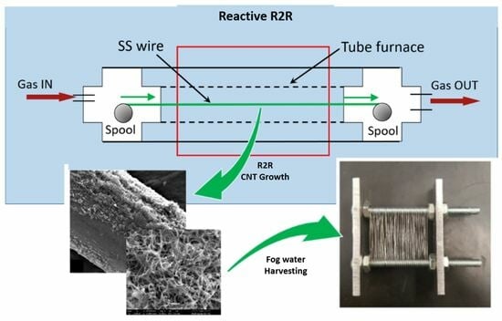
3. Generation of a CNT-on-SS Wire Structure in a Continuous RR2R Process

The proposed solution scheme enables the durability of the coating and allows the generation of very large surfaces for fog droplet capture. This last point is a key requirement for fog harvesters and also forms a new proposal for enabling very large surface areas of CNT-based forest structures for other applications. Our solution scheme follows the Direct-Growth process of CNT forests generated on SS wires using thermal chemical vapor deposition (th-CVD), as developed by Baddour et al. in 2009 [32]. The specificity of this particular technique largely simplifies the synthesis process for scale-up and is compatible with large surface area requirements. More importantly, it enables strong anchoring of the CNTs on the SS support in order to maintain hydrophobicity over time [33]. In order to help optimize both the capture and the removal of water droplets, the structure to be generated would also benefit from the inclusion of both hydrophilic and hydrophobic regions. This can readily be obtained in the Direct-Growth process through control of the scale of the forest patches.
Chemical vapor deposition (CVD) techniques are often used to generate forests of CNT on a surface. These technologies are generally based on the use of metal catalyst nanoparticles acting essentially as templates for extracting the dissolved carbon in an eutectic-like transformation. The size of the nanoparticle is important, with diameters roughly below the 50–60 nm range being necessary for generating multi-wall nanotubes (MWNT). The th-CVD method based on a tube furnace is chosen in this work for its simplicity, particularly for applications requiring important scale-up. As discussed in the Introduction, this procedure typically involves the addition of catalyst nanoparticles in the synthesis process, the most common materials being Fe, Ni, and Co. However, the Direct-Growth method eliminates the requirement for this external catalyst by generating surface topography defects that are equal or smaller to the 50–60 nm size range (Figure 2). These defects are intrinsically part of the material surface and, in particular, are not nanoparticles added to the surface. Such defects are achieved via mild acid etching of the surface and/or surface material recrystallization. The etching and/or material recrystallization processes are used for generating the nanoscale topography and are adjusted to the specific surfaces of the stainless-steel (SS) substrate. It is important to note that every SS substrate geometry chosen, for example, fine wires in the present application, has gone through various thermal and forming operations during the original bulk and final material fabrication processes. These operations, and particularly the drawing operation used to fabricate the wires to be used in the present process, modify the grain structure and surface topography of the material. This results in the necessity of adjusting the mild acid pre-treatment recipe and recrystallization stage for generating nanoscale defects when changing the SS material geometry, such as wire diameter or flat planar structures. A cleaning step followed by mild acid etching typically forms the very simple preparation steps for growing CNT forests on SS wires through the Direct-Growth approach, i.e., no catalyst nanoparticles are to be added for generating the dense CNT structures. Well-anchored forests of nanotubes are readily grown with a strong adherence to the SS surface. Such forests were shown to be available for chemical or plasma functionalization and possibly ultrasonic dispersion if required for nanofluid generation [34]. As stated in the Introduction, ultrasonic harvesting of the forests shows CNT trunks still present on the surface after the harvesting step, indicating the strong anchorage effect of using nanoscale surface defects instead of deposited catalyst nanoparticles.
Herein, we adapt the Baddour protocol, a batch process, to operate under continuous RR2R processing, demonstrating a simple method for catalyst-free continuous CNT-forest growth. This method maintains CNT anchoring to the surface to form a forest-like structure, providing good physical and chemical access to the CNT structures, with the inter-tree distance essentially controlled with the nanoscale surface topography generated. The resulting structure forms a CNT forest on SS that can be manipulated for various applications and physical/chemical surface modifications.

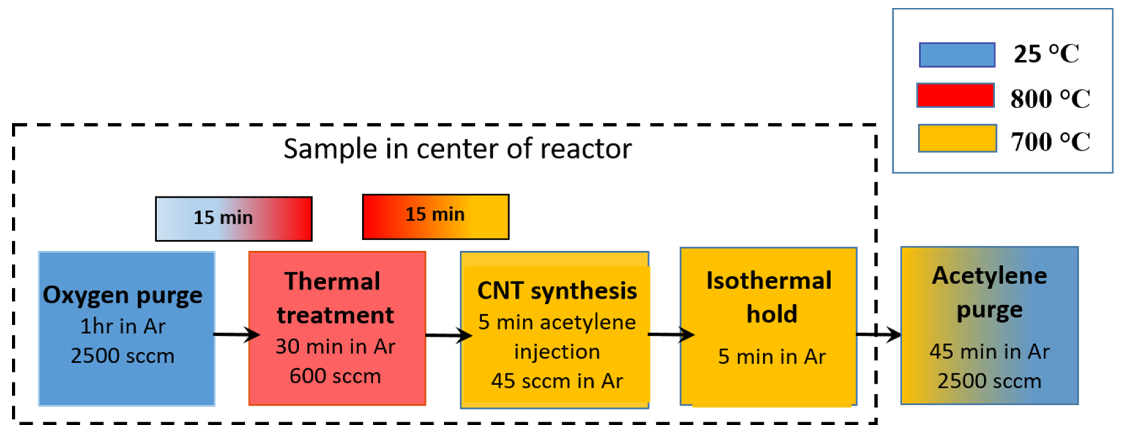
Methodology for Dynamic RR2R MWCNT Growth

The substrates employed are stainless-steel wires (SS 304; D = 0.18mm, (McMaster-Carr, Elmhurst, IL, USA). The wires are first cleaned with acetone (Fisher Scientific Co., Ottawa, ON, Canada) for 10 min in an ultrasonic bath (Branson 2510 Ultrasonic Cleaner, Vaughan, ON, Canada). Etching allowed for surface roughness generation through immersion in HCl for 2 min (37%, ACS reagent, Sigma-Aldrich, Oakville, ON, Canada). This is followed by ultrasonic cleaning in a deionized water bath for 10 min. The preparation steps based on acid etching and thermal recrystallization aim to generate nanoscale surface defects, i.e., bumps that are inherently part of the SS structure and not added nanoparticles. Hence, etching times tend to vary with wire diameter, as their initial fabrication process results in different grain sizes and morphologies. Following the etching and cleaning steps, the wire samples go through a last preparation step consisting of recrystallization of the material for 30 min at 800 C under an Ar atmosphere (furnace details provided below). This last step provides the nanoscale bumpy surface morphology necessary to trigger CNT growth from the bulk surface.
The thermal treatment for CNT forest generation is conducted in a tubular furnace (Figure 3) having an RR2R configuration with wire spools located outside and on each side of the furnace (Lindberg/Blue M, HTF 55322A series, Riverside, MI, USA) in manipulation chambers (MDC Precision LLC, Hayward, CA, USA). The reactor used was a quartz tube (OD = 58 mm; ID = 52 mm; and L = 1.2 m) mounted in the tubular furnace, and the SS wire was suspended and fed along the central axis of the quartz tube. Argon and acetylene are introduced to the reactor at 68.9 kPa via a 6.35 mm ceramic tube and are exhausted via a larger 63.5 mm tube in order to prevent gas recirculation at the outlet and the possible generation of contaminants. An oxygen analyzer (Series 2000, Alpha Omega Instruments, Houston, TX, USA) is installed at the exit of the system for monitoring and safety purposes. Modeling of the oxygen concentration was also accomplished using the COMSOL Multiphysics software (COMSOL Inc, Burlington, MA, USA), this indicated that an initial argon purging during a period of 40 min provided safe operating conditions.
The velocity of the wire used in the RR2R configuration ranged from 0 m/s (simulating static/batch conditions) to 9.32 × 10⁻⁴ m/s (or 5.6 cm/min). A stepper motor (Pololu Tic T834, 3 V, 1.7 A, 400 steps, Arduino controller) was used with a rotary movement feedthrough (MDC Vacuum) in the downstream chamber to drive the wire.
For control purposes, the same wire pre-treatment steps and CNT growth protocol were also repeated in batch static experiments, with the entire wire being loosely rolled up and supported in a ceramic boat in the center of the furnace rather than suspended and fed along the furnace’s central axis. These static experiments provided the bottom line for evaluating preliminary synthesis temperatures and the duration of the growth steps for the SS wires. Figure 4 presents a summary of the various treatment steps in the oven during these static experiments.
Another substrate geometry was also carried out in static mode using stainless-steel grids of a mesh size of 400, following the methodology developed by Baddour et al. [32] and Hordy et al. [33]. The interest in such geometry is that it mimics the grid pattern of many fog harvesters and extrapolates the RR2R process to other geometries.

4. Experimental Results

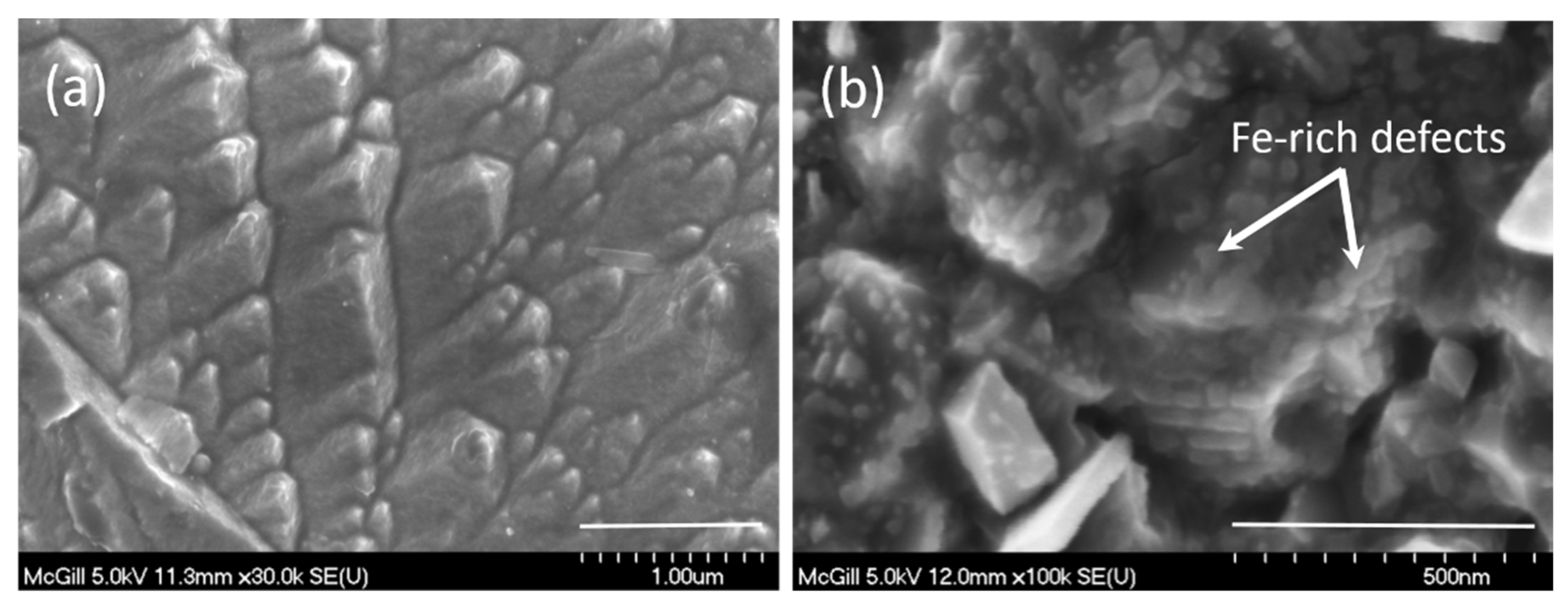
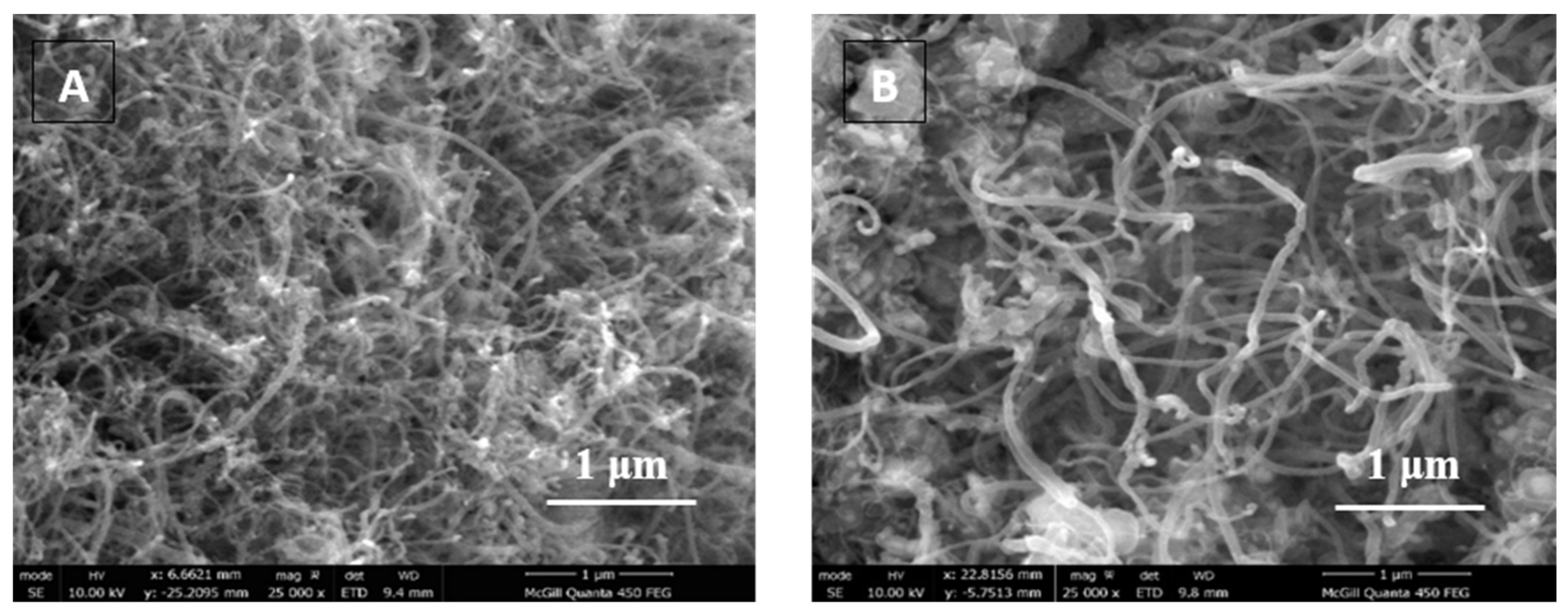
4.1. CNT Static Growth on SS Wires

Static growth of CNTs was first carried out on long (up to 6 m) stainless-steel wires using the described th-CVD method. Other samples without HCl pre-treatment were also produced for CNT growth. The various samples were placed on a quartz boat in the middle of the furnace, and a heat pre-treatment was conducted at 850 °C for 30 min. As indicated in Section 3, this high-temperature sequence corresponds to the recrystallization stage of SS for generating nano-scale defects at the surface of the metal. After this initial heat treatment, the furnace temperature was set to 775 °C and purged for 5 min under a 2500 sccm Ar flow to remove oxygen (O2) from the quartz tube. Once the O2 level reaches a value below 0.5% on the O2 analyzer, C2H2 is introduced at a flow rate of 45 sccm for 5 min, during which time Ar flow is reduced to 600 sccm. After 5 min of C2H2 injection, the sample remained inside the reactor for an additional 5 min under 600 sccm Ar. This corresponds to the growth phase of the CNTs. The reactor was subsequently purged with Ar at 2500 sccm for 45 min to remove C2H2 remnants, and the furnace was shut down. Upon the furnace reaching room temperature, these static-growth samples covered with CNT are removed.

4.2. CNT Static Growth on SS Grids

To enable a comparison of the harp fog harvesting geometry (constructed using very long CNT-covered wires) to the traditional meshed fog harvesting geometry, a series of CNT-covered SS 316 grids with a mesh size of 400 were also produced. The same cleaning step was used based on sonication in acetone for 10 min. Following the Hordy et al. protocol, acid pre-treatment is not required for the growth of CNTs on the SS 316 grids [31]. This follows mesh wires of 30 μm in diameter being formed through an extensive extrusion process, generating nanoscale grain defects. In comparison, the wires used for generating the fog harvester harps have a much larger diameter of 180 μm and are subjected to much less deformation in the extrusion process, generating a need for acid etching to create nanoscale defects. The cleaned and air-dried SS grids were subsequently introduced inside the furnace set at 725 °C, and the same procedure previously described was carried out. The SS grids, before and after the CNT-forest growth, are shown in Figure 5.

4.3. Transition from Static to Moving Wire

A series of tests were required to enable the tuning of the CNT growth when changing from static conditions in the furnace, as described in Section 4.1 and Section 4.2, to a moving wire located all along the furnace tube axis. Both the thermal history of a given section of the wire and the time scales of contact with the carbon precursor gas are inherently modified from the original CNT growth protocol. In the original Baddour et al. protocol (see Figure 4), the samples are located in the central zone of the furnace with the highest temperature and first go through an initial period of heating in Ar for nanodefect generation. This is followed by the acetylene/argon carbon loading sequence of the surface, and typically a 5 min growth period of the CNT in argon. In a continuous RR2R mode, both the initial and final Ar steps need to be eliminated, leaving only a uniform C2H2/Ar flow during the process. The axial temperature profile is crucial for achieving good growth conditions in RR2R mode, as it is a combination of temperature profile and wire velocity that enables proper carbon loading and CNT growth. Figure 6 shows typical temperature profiles in the furnace when using two different temperature set points.
Axial temperature profiles were measured in the furnace, together with modeled estimations of the convective and conductive heat fluxes to and within the wire. Static tests (i.e., wire velocity = 0) in the RR2R wire geometry (i.e., wire in the central axis of the furnace) for CNT growth were also made to adjust the CNT growth temperature. These thermal calculations and tests resulted in a requirement for increasing by 25 °C (i.e., to 725 °C) the temperature set point for generating good CNT forest growth in these static tests. Such a temperature increase essentially compensates for the axial heat losses within the metallic wire. Figure 7 shows the typical CNT-forest growth obtained on the wire in RR2R static conditions for two C2H2 flow durations and Ar growth periods. Figure 7 shows that two different growth time scales could achieve good CNT-forest growth in static conditions. In the case of Figure 7B, eliminating the isothermal waiting period with Ar flow from the original protocol (see Figure 4) did not affect the possibility of growing CNT forests. This agrees with the original Baddour et al. tests indicating the “growth period” is, in fact, very fast and does not require an extensive waiting time under Argon.
Temperature measurements along the tube axis indicate the reacting area (T > 650 °C) is roughly equivalent to the length of the heating element of the furnace. Two wire speeds are chosen for demonstrating CNT generation in a dynamic RR2R configuration: 5.6 cm/min representing a residence time of 5 min in the reactive nucleation/growth zone (NGZ) as used in the static Baddour-based protocol and 2.8 cm/min representing a residence time of 10 min in the same NGZ. The NGZ here essentially corresponds to the space between the (b) and (c) boundaries indicated in Figure 6. Figure 8 provides a series of SEM results for these RR2R-dynamic CNT growths.
Figure 8a shows the bare SS wire following the pre-treatment sequence (etching and recrystallization) before insertion in the RR2R furnace. Figure 8b shows a CNT growth pattern in static conditions when no acid etching is made, while Figure 8c is under similar conditions but with acid pre-treatment. Two patterns can readily be observed on the SS wire. Figure 8b first shows large CNT growth sections aligned with the wire-forming extrusion lines (see Figure 8a) and important no-growth zones with the same alignment. The pattern of Figure 8c is different by showing well-mixed small islands of CNT growth that tend to be isolated from each other. Figure 8d–f are dynamic growth sequences under two different wire speeds, respectively 5 min (Figure 8d,e) and 10 min (Figure 8f) in the NGZ. Figure 8d is a close-up of the local CNT forest pattern seen in Figure 8e, where similar CNT islands indicate CNT structures in the order of one to a few micrometers in length and the presence of some amorphous carbon structures (Figure 8f). All the above 8a–f, i.e., including the dynamic growth samples d–f, are generated using the standard furnace temperature protocol of 700 °C. Figure 8g,h follow a similar time sequence of 5 min in the GZ as used for samples d and e, but with a furnace temperature increased to 725 °C to compensate for the heat losses along the wire. Figure 8g clearly shows a cleaner growth pattern with longer CNT structures, fewer defects, and less amorphous carbon compared to Figure 8d,f. This clearly indicates that a moving SS surface in an RR2R protocol can readily be tuned for continuous CNT-forest growth using similar sample preparation processes. The pattern in Figure 8h also shows dense growth zones adjacent to low-density growth, both of which are aligned with the surface defects generated by the extrusion forming of the wire, as observed in the static case of Figure 8b. In other words, dynamic RR2R CNT-forest growth can readily replicate static CNT-forest generation structures.
It is important to note that growth patterns, as seen in Figure 8, are extremely interesting in the context of fog harvesting. Remembering that the micro-physics of fog harvesting requires a hybrid structure showing both hydrophilic and hydrophobic regions in order to enable the capture (hydrophilic regions, SS surface) and the efficient removal (hydrophobic regions, CNT forest) of the water droplets. In this context, full CNT coverage of the SS wire seems a priori not to be desired. The RR2R results of Figure 8 provide a basic template for enabling the testing of SS/CNT gradient wettability in harp fog harvesters.

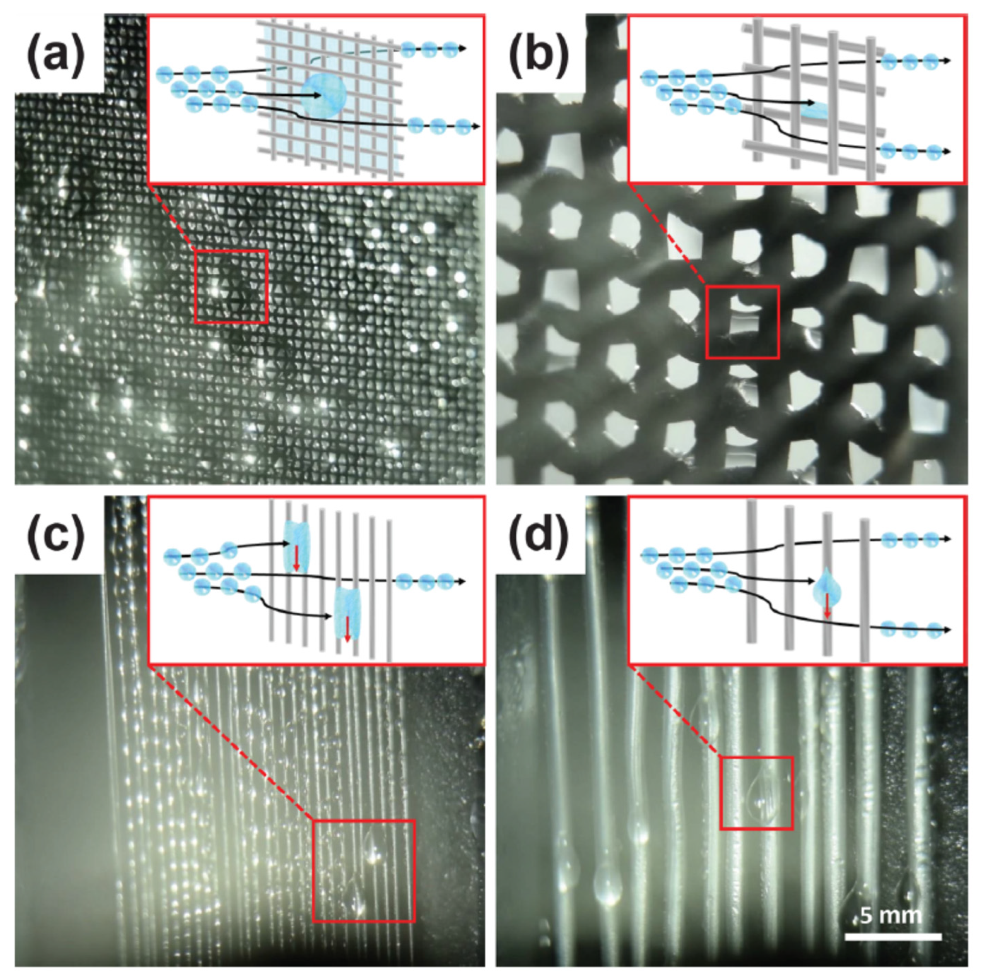
5. Fog Harvesting Experiments

In our experiments, the samples in Figure 8b,c,e,h are examples of wire surfaces where hydrophobic CNT forests and hydrophilic SS are present in unison; these are being used for the harp-based fog harvesting tests. Wires with complete CNT-forest coverage were also utilized to fabricate purely hydrophobic harps, as well as bare SS wires with no CNT present, such as in Figure 8a.

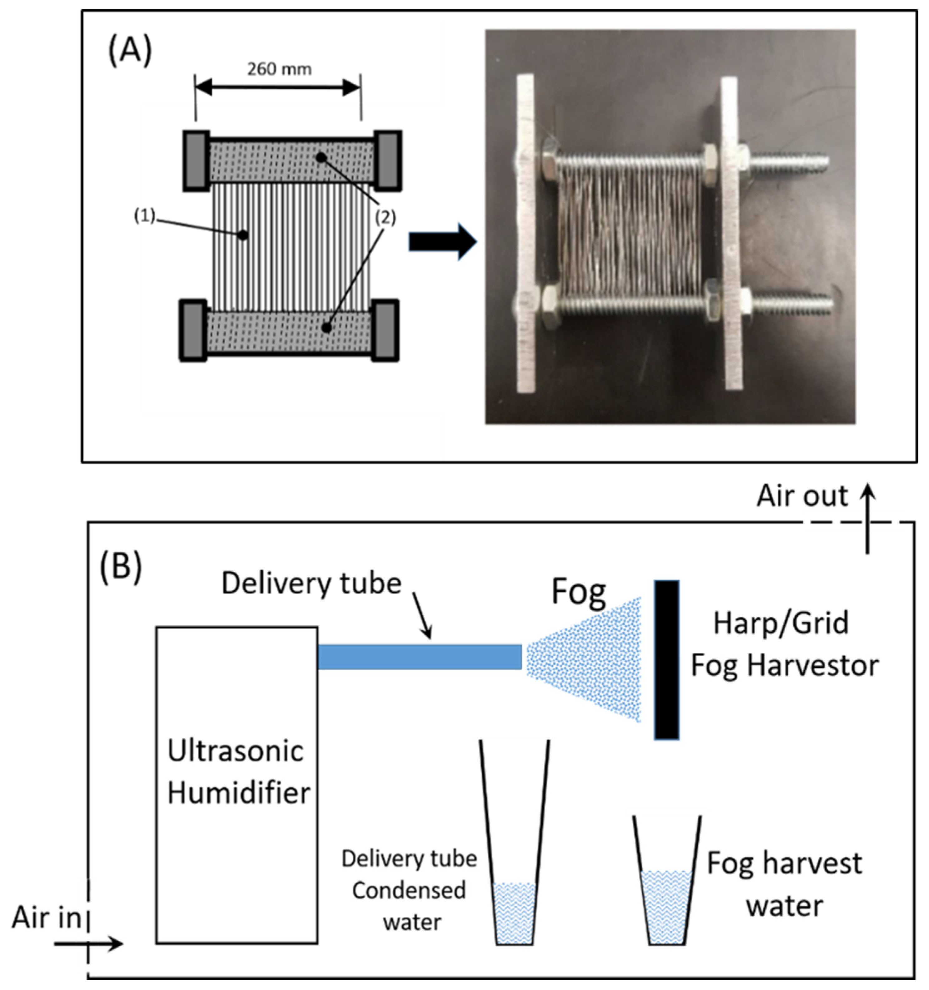
5.1. Fog Harvesting Setup

A small and simple harp-type fog harvester was assembled to enable a proof-of-concept of the continuous SS/CNT wire for fog harvesting. No detailed parametric study or optimization process is made here, the objective being to verify the potential for water collection on such a structure. The structure is made using two SS screws of 10–32 thread type, supported by two SS metal plates (60 × 20 mm), all together forming the framework for the harp harvester (Figure 9). Long SS wires of 180 μm diameter and around 3 m in length, with or without CNT-forest coverage from the RR2R process, were wired vertically and parallel to one another using the top and bottom SS screw threads as a guide and held under tension. The pitch of 800 µm, in other words, the distance between two adjacent wire surfaces, was previously optimized in a study by Alessio et al. in which harps were assembled with pitches ranging from 400 to 1400 µm. This harp configuration, as well as bare SS grids and SS-CNT grids, were installed on a supporting frame and used for the various fog harvesting tests.
The fog harvesting experiments were conducted in a closed compartment constructed of clear acrylic glass (Figure 9B). An exhaust line was attached to the top surface of the overall container to minimize water droplet condensation that may interfere with the measurements. The fog was generated using an ultrasonic humidifier (Crane, model no. 5301BB, 45 W, Itasca, IL, USA) and transported using a transparent flexible tube, directing the fog towards the harp assembly. The ultrasonic humidifier consists of piezoelectric ceramic discs that oscillate at ultrasonic frequencies of around 1–2 MHz [38] and generate water microdroplets of 1–5 µm in size [39,40], corresponding to the size range of natural fog microdroplets [41,42]. The grids or harp samples were held in position at a distance of 6 cm from the fog transport tube outlet and held perpendicular to the fog stream [30].
The water was collected in a graduated beaker placed directly beneath the sample and weighed to evaluate the total amount of water collected. For any given test, the exact volume of water that contributed to the fog generation from the humidifier was measured, together with the water lost via condensation in the delivery tube. The value of the water removed from the fog generator and condensation before reaching the harvester is then used to measure the exact amount of fog that is transported on the sample surface. The volumetric flow rate at the fog outlet was 3.26 ± 0.09 (std) cc/min, and the volumetric flow rate at the surface of the fog harvester was evaluated to be 1.44 ± 0.26 cc/min. Water collection was assessed after a pre-specified volume of water was emptied from the ultrasonic humidifier, and collection efficiency was evaluated based on both the collection time and surface area of the fog harvesters, as shown in Equation (1).
m collected g c m 2 · h = Weight of water after experiment Active surface area Experiment duration
The ambient temperature and the relative humidity were monitored at all times during the fog harvesting experiments and the data collection. The ambient temperature in the fog setup was maintained in the range between 19.5 °C and 21 °C, and the relative humidity ranged between 32 and 46% for all experiments. No substantial differences were observed in tests made under these varying ambient conditions of temperature and humidity. In particular, the change in ambient humidity outside of the fog harvester unit is believed to have little influence on the large amount of fog water mass delivered to the harp/grid harvester.

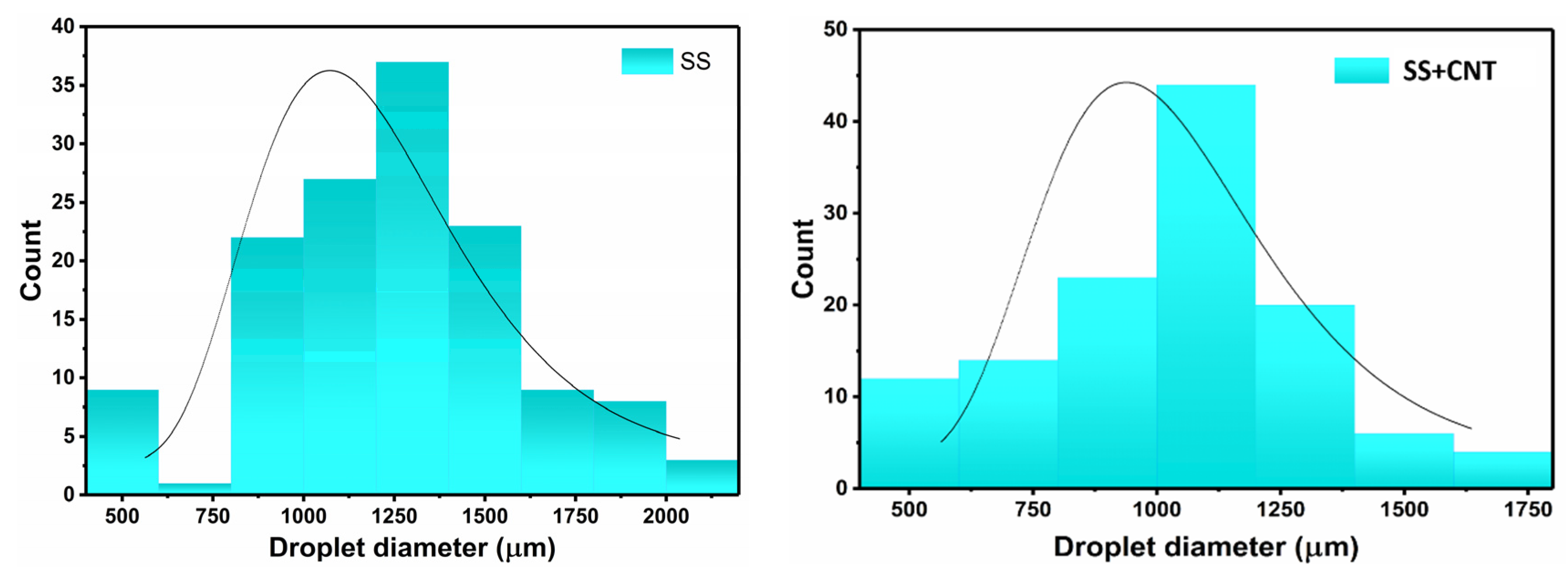
5.2. Fog Harvesting Results

Fog capture tests were first made on individual isolated vertical wires with the goal of measuring the respective time needed for droplet coalescence and fall on bare SS wires and CNT-covered SS wires, respectively. For the same fog-laden air flux, coalesced droplets on bare SS wires dropped along the wire after 340 s, while CNT-covered SS wires showed coalescence and dropped after only 151 s. Rapid coalescence and droplet fall are advantageous for fog-based water capture. The droplet size distribution observed on the SS harp is provided in Figure 10. A droplet diameter typically reaching 1250 ± 250 μm is observed upon sliding down the harp wire.
When subjected to the fog, the bare SS harp without CNT-forest coverage recorded water collection rates of typically around 1.3 g/cm2·h, while the covered and partly covered CNT-forest-coated harp registered rates going up to 2.2 g/cm2·h (Figure 11). This increase in water collection rate is expected to be generated by the rapid shedding of water microdroplets in the CNT-covered harp. On hydrophobic CNT-covered wires, the water microdroplets coalesce to form large clamshell-like shapes [43]. The gravitational forces from the vertical harp design assist the droplets in overcoming the adhesive forces, retaining them to the wire, and hence getting easily collected. Moreover, the CNT forest-like structure provided a larger surface area, presenting additional sites for water droplets to adhere. Although still at a preliminary study level, it is interesting to see in Figure 11 the gradual improvement in water collection when going from (i) pure SS wires to (ii) CNT with gradient wettability wires and to (iii) fully CNT-covered wires. There is also a striking difference in water collection efficiency when comparing the above results to both the SS and CNT-covered grid systems. This follows very well the concept elaborated by Shi and co-workers [31], who introduced the harp configuration by eliminating the transverse wires in the grids. Various harp designs with multiple stages have been suggested following their research. However, the majority of the water harvesting investigations focused on SS, aluminum wires, and polymer-based materials sometimes coated with aluminum [1,24,29], with the highest reported water collection rates close to 3 g/cm2·h.
As indicated above, the scope of our work was not to optimize water harvesting through a multi-parameter study but to shed light on the impact of CNT forest-like structures and surface wettability on water capture and to provide a demonstration that gradient wettability surfaces can readily be generated using known carbon nanotube generation protocols. Surprisingly and contrary to our initial expectations on the benefits of gradient wettability for water removal, the highest collection rate of 2.2 g/cm2·h corresponds to a case where full coverage of CNT forest is observed on the wire. The value of 2.2 g/cm2·h is slightly lower than the highest achieved results of Shi et al. [30], who reached 3 g/cm2·h on harp-based systems, and still further away from nature-inspired architectures, reaching up to 5.3 g/cm2·h, as stated in the Introduction. The present approach, however, enables the production and control for generating wettability gradients on a surface at the microscopic level; this is made in a relatively simple way and yet easily scalable through the RR2R process. It is an approach where the inherent hydrophilicity of the SS substrate has been exploited, while th-CVD-grown CNT forests have been utilized for their hydrophobicity and seem to strongly enhance water collection.
From a geometric configuration point of view, harp-based harvesters exhibited clear superiority to grid-based systems, with the SS grid collection rate limited to 0.14 g/cm2·h (Figure 11 for grid systems). While this can be improved to ~0.26 g/cm2·h by coating the grids with CNTs, the CNT-covered harp-based harvester performed ~8 times better than the CNT-covered grid harvester and ~15 times better than the bare SS grid harvester. The primary reason for the superior performance of harp-based harvesters is the absence of orthogonal wires that are present in grids, allowing the water droplets to slide down the wires effortlessly. Furthermore, clogging and pinning of water droplets inside the grids hinder fog flow by blocking the preferential pathway of fog [30].
As indicated by Schemenauer et al. [44], it is also important to note that the size and geometry of the fog harvester have a strong effect on the water recovery yields. For example, Schemenauer et al. indicate that the yields of the harvester vary between the center and the sides of large fog harvesters because of their influence on the airflow pattern. Small lab-scale experiments, as made in the present study, mainly provide standardized values for comparative studies on the structure and properties of the collecting device material. By no means can such studies be extrapolated to very large fog collection devices.
In addition to achieving good water collection rates in harp-based fog harvesters, long-term durability is also a critical issue that needs to be addressed. Preliminary durability tests were carried out on the CNT-based harp over a relatively short period of 12 days. The results indicated that no statistically significant change in efficiency could be observed over this time scale for the CNT-covered harp fog harvester. The durability measurements were carried out under laboratory conditions, and the stability of the CNT-based harps in an outdoor climatic condition needs to be further evaluated. As a reminder, the Direct-Growth technique of CNT-forest on SS provides a strong anchorage of the CNT roots onto the metal substrate. Hordy et al. demonstrated a preparation technique for nanofluids using 3 h of sonication of the CNT forest on SS grids in water [31]. As indicated earlier, such harsh harvesting of the CNT forest results in leaving the SS surface covered with CNT “trunks”. Their observations from surface morphological characterizations indicated that the CNTs were only harvested from slightly above the SS surface and not extracted from the CNT-SS interface. This observation provides a good insight into the excellent anchorage and durability of the SS-CNT structures based on the primary bonds at the CNT-metal carbide interface.

6. Discussion

Besides the present fog harvester application, other technologies may also find of interest the ability to grow forests of CNT on very large surfaces, particularly considering the strong root anchoring of this forest on its ground. A series of potential applications already exist and are limited in our capacity to produce large surfaces with well-anchored CNT forests. To name a few, the RR2R process developed here on wires can easily be transferred to grid ribbons for enhanced nanofluid volume preparation. CNT-based stable nanofluids require oxygen functionalization, which is very easily achieved when using a plasma treatment on a well-anchored CNT forest, followed by ultrasonic sonication for dispersion in the fluid [31]. Other applications of anchored CNT forest surfaces could be (i) for enhancing heat transfer to the surface in fluid-based systems, (ii) for enhancing catalytic reactions with added catalyst nanoparticles on the CNT forest [45], (iii) for providing better radiation capture, for example, in heat recovery/transport of high-power solar-based power plants [46], (iv) for enhanced heat absorption and recovery from hot surfaces or better heat dissipation through radiative cooling, (v) for enhanced separation processes, for example in the capture of nanoparticles in gaseous or fluidic systems [47], and (vi) for improved super-capacitor electrodes [48]. All the above examples require both the strong anchorage of the CNT forests and the possibility of generating large CNT-covered surfaces for enhanced efficiency of the specific application. The RR2R process presented here provides a solution for many technological challenges.

7. Conclusions

We present here a continuous in-line CNT-forest growth process using a reactive-roll-to-roll (RR2R) technique based on the Direct-Growth method, providing a strong anchoring of the CNT structures on the substrate. A simple thermal-CVD method is used in the RR2R geometry, strongly minimizing the cost of such anchored forest-like structures. The etching and recrystallization pre-treatments enable a nanoscale topography on the surface, which acts as CNT growth sites that are inherently part of the substrate. This eliminates the requirement for catalytic nanoparticles and ensures the CNT roots are very strongly attached to the stainless-steel “ground”. This process provides important scaling for very long CNT-covered wires produced in a continuous RR2R configuration. It also opens the road to the fabrication of very large CNT-covered surfaces. The scale-up of well-anchored CNT forest generation and functionalized CNT forests should strongly reduce the cost of these structures as well as enable a series of new applications.
A practical demonstration of the new process and material structure developed is also applied here to an environmental problem linked to atmospheric water harvesting. Long wires covered with a CNT forest are made using the RR2R process and evaluated as potential fog water harvesting devices for specific regions of the world. Interestingly, the RR2R process also brings the possibility to tune regions of the wire into hydrophobic CNT-forest regions and hydrophilic stainless-steel surface regions of various geometry. Such tuning capability is believed to help the process of optimizing fog water recovery. With the objective of verifying the potential of water collection in such a structure, long CNT-covered stainless-steel wires were winded in a vertical parallel “harp-type” array for fog droplet collection. A systematic investigation was carried out on different fog harvesters made using the RR2R process, each having different CNT coverage and two different geometries, namely the harp-type arrangement and grid-type structures. Although no optimization process was made, the water collection efficiency of the CNT-forest harp system exhibited a nearly two-fold increase in comparison to the bare SS harp fog harvesters. Such preliminary tests indicated water recovery yields of 2.2 g/cm2·h. The enhanced water capture of the CNT-covered harps is attributed to their increased surface area and hydrophobicity, enabling a faster removal of the water droplets. It is believed, however, that fine-tuning the size and geometry of the hydrophilic and hydrophobic regions, respectively, could enable optimization for increasing water capture efficiency. As indicated by Schemenauer [45], it is important to note that the size and geometry of the fog harvester have a strong effect on the water recovery yields. For example, Schemenauer indicates that the yields of the harvester vary between the center and the sides of large fog harvesters because of their influence on the airflow pattern. Small lab-scale experiments, as made in the present study, mainly provide standardized values for comparative studies on the structure and properties of the collecting device. Durability tests carried out over 12 days indicated that MWCNT harp fog harvesters retained their initial water collection efficiency. The results establish fog harvesters based on wires covered by CNTs in a harp configuration as a promising and stable solution for future fog harvesting systems.
The benefits of an RR2R generation, particularly for fog harvesting applications, can be summarized as follows:
  • The direct growth technique uses a material-specific design for generating nanoscale surface roughness patterns for CNT nucleation and growth and provides a CNT forest anchorage with primary bonds with the host surface. In other words, the CNT forest is inherently linked to strong anchorage to the SS surface;
  • No external catalyst, dye solution, slurry, or other deposition technique is required; it is the stainless-steel substrate itself that is acting as the CNT growth and anchoring site;
  • The simple catalyst-free RR2R technique continuously generates reliably very long CNT-covered wires able to generate the very large collecting surfaces required, together with a CNT forest oriented in a direction perpendicular to the surface;
  • The CNT-covered wires intrinsically provide a much larger surface area for atmospheric-suspended micro-droplet collection compared to bare wires. More importantly, both of the required local hydrophilic/hydrophobic properties needed for water capture and drainage are generated;
  • Finally, in view of possibly extending the RR2R technique to other applications requiring large surfaces and various geometries, it is to be noted that the Direct-Growth technique based on a relatively simple metallurgical surface transformation allows the possibility of various surface shapes and sizes, as was previously demonstrated by growth generated on particles, flat surfaces, and grids.

Author Contributions

Conceptualization and methodology: J.-L.M., J.O. and K.B.; Investigation and Validation: J.O., K.B., A.A., J.R.T. and J.-L.M.; Writing Original draft preparation: J.-L.M.; Writing, review and editing: J.-L.M. and J.R.T.; Resources: R.B. and J.R.T.; Supervision, funding acquisition and project administration: J.-L.M. and J.R.T. All authors have read and agreed to the published version of the manuscript.

Funding

This work was supported by the Natural Sciences and Engineering Research Council of Canada (NSERC), Grant number NSERC RGPIN-2018-04425.

Data Availability Statement

The data related to the present research can be found in the two Master of Engineering thesis related to the project, namely: (1) Jeanne Ouellet, Croissance de nanotubes de carbones en continu pour produire des harpes permettant de collecter les microgouttelettes d’eau du brouillard, Master of Applied Sciences, Chemical Engineering, Polytechnique Montreal, December 2020. (2) Alessio Aufoujal, Physical and chemical approaches for water micro-droplet capture, Master of Applied Sciences, Chemical Engineering, Polytechnique Montreal, April 2020.

Acknowledgments

The authors acknowledge the support of David Liu and Jesus Valdez Aguilar at the McGill Institute for Advanced Materials (MIAM) and the Facility of Electron Microscopy Research (FEMR) for helping with the microscopy techniques. We also acknowledge Frank Caporuscio, Ranjan Roy, Luciano Cushmich, and Andrew Golsztajn at the Chemical Engineering Department of McGill University for their technical support. Similarly, we acknowledge the technical support staff at Polytechnique Montreal, Chemical Engineering Department for their contributions on fog harvesting studies.

Conflicts of Interest

Author Richard Boudreault is the founder of the new startup company Awn Nanotech Inc. and declares no conflict of interest with the research presented in the present publication. The remaining authors declare that the research was conducted in the absence of any commercial or financial relationships that could be construed as a potential conflict of interest.

References

  1. Abdul-Wahab, S.; Lea, V. Reviewing fog water collection worldwide and in Oman. Int. J. Environ. Stud. 2008, 65, 487–500. [Google Scholar] [CrossRef]
  2. Schemenauer, R.; Fuenzalida, H.; Cereceda, P. A Neglected Water Resource: The Camanchaca of South America. Bull. Am. Meteorol. Soc. 1988, 69, 138–147. [Google Scholar] [CrossRef]
  3. Jarimi, R.; Powel, R.; Riffat, S. Review of sustainable methods for atmospheric water harvesting. Int. J. Low-Carbon Technol. 2020, 15, 253–276. [Google Scholar] [CrossRef]
  4. Klemm, O.; Schemenauer, R.S.; Lummerich, A.; Cereceda, P.; Marzol, V.; Corell, D.; Van Heerden, J.; Reinhard, D.; Gherezghiher, T.; Olivier, J.; et al. Fog as a Fresh-Water Ressource: Overview and Perspectives. AMBIO 2012, 41, 221–234. [Google Scholar] [CrossRef] [PubMed]
  5. Qadir, M.; Sharma, B.R.; Bruggeman, R.; Choukr-Allah, R.; Karajeh, F. Non-conventional water resources and opportunities for water augmentation to achieve food security in water scarce countries. Agric. Water Manag. 2007, 87, 2–22. [Google Scholar] [CrossRef]
  6. Schemenauer, R.S.; Cereceda, P. Fog-Water Collection in Arid Coastal Locations. Ambio 1991, 20, 303–308. [Google Scholar]
  7. Pangarkar, B.; Sane, M.; Guddad, M. Reverse Osmosis and Membrane Distillation for Desalination of Groundwater: A Review. ISRN Mater. Sci. 2011, 2011, 523124. [Google Scholar] [CrossRef]
  8. Zotalis, K.; Dialynas, E.; Mamassis, N.; Angelakis, A. Desalination technologies: Hellenic experience. Water 2014, 6, 1134–1150. [Google Scholar] [CrossRef]
  9. Jones, E.; Qadir, M.; Van Vliet, M.; Smakhtin, V.; Kang, S. The state of desalination and brine production: A global outlook. Sci. Total Environ. 2019, 657, 1343–1356. [Google Scholar] [CrossRef]
  10. Gude, V. Energy consumption and recovery in reverse osmosis. Desalination Water Treat. 2011, 36, 239–260. [Google Scholar] [CrossRef]
  11. Al-Karaghouli, A.; Kazmerski, L. Energy consumption and water production cost of conventional and renewable-energy-powered desalination processes. Renew. Sustain. Energy Rev. 2013, 24, 343–356. [Google Scholar] [CrossRef]
  12. Greenlee, L.; Lawler, D.; Freeman, B.; Marrot, B.; Moulin, P. Reverse osmosis desalination: Water sources, technology, and today’s challenges. Water Res. 2009, 43, 2317–2348. [Google Scholar] [CrossRef] [PubMed]
  13. Beltran, J.; Koo-Oshima, S. Water Desalinisation for Agricultural Applications; Food and Agriculture Organization of the United Nations: Rome, Italy, 2006. [Google Scholar]
  14. WHO. Technical Notes on Drinking-Water, Sanitation and Hygiene in Emergencies. Available online: https://cdn.who.int/media/docs/default-source/wash-documents/who-tn-09-how-much-water-is-needed.pdf?sfvrsn=1e876b2a_6 (accessed on 3 January 2024).
  15. Gleick, P.H. Water in Crisis—A Guide to the World’s Fresh Water Resources; Oxford University Press: Oxford, UK, 1993; pp. 13–24. [Google Scholar]
  16. Legrand, U.; Klassen, D.; Watson, S.; Aufoujal, A.; Nisol, B.; Boudreault, R.; Waters, K.; Meunier, J.L.; Girard-Lauriault, P.L.; Wertheimer, M.; et al. Nanoporous sponges as carbon-based sorbents for atmospheric water generation. Ind. Eng. Chem. Res. 2021, 60, 12923–12933. [Google Scholar] [CrossRef]
  17. Zhang, Y.; Tan, S. Best practices for solar water production technologies. Nat. Sustain. 2022, 5, 554–556. [Google Scholar] [CrossRef]
  18. Bai, H.; Wang, L.; Ju, J.; Sun, R.; Zheng, Y.; Jiang, L. Efficient Water Collection on Integrative Bioinspired Surfaces with Star-Shaped Wettability Patterns. Adv. Mater. 2014, 26, 5025–5030. [Google Scholar] [CrossRef]
  19. Shang, L. Bioinspired Multifunctional Spindle-Knotted Microfibers from Microfluidics. Small 2017, 14, 1600286. [Google Scholar] [CrossRef]
  20. Yu, Z.; Yun, F.F.; Wang, Y.; Yao, L.; Dou, S.; Liu, K.; Jiang, L.; Wang, X. Desert Beetle-Inspired Superwettable Patterned Surfaces for Water Harvesting. Small 2017, 13, 36. [Google Scholar] [CrossRef]
  21. Shi, W.; De Koninck, L.H.; Hart, B.J.; Kowalski, N.G.; Fugaro, A.P.; Van der Sloot, T.; Ott, R.S.; Kenedy, B.S.; Boreyko, J.B. Harps under Heavy Fog Conditions: Superior to Meshes but Prone to Tangling. ACS Appl. Mater. Interfaces 2020, 12, 48124–48132. [Google Scholar] [CrossRef]
  22. Lei, J.; Guo, Z. A fog-collecting surface mimicking the Namib beetle: Its water collection efficiency and influencing factors. Nanoscale 2020, 12, 6921–6936. [Google Scholar] [CrossRef]
  23. Wen, C.; Guo, H.; Bai, H.; Xu, T.; Liu, M.; Yang, J.; Zhu, Y.; Zhao, W.; Zhang, J.; Zhang, L. Beetle-Inspired Hierarchical Antibacterial Interface for Reliable Fog Harvesting. ACS Appl. Mater. Interfaces 2019, 11, 34330–34337. [Google Scholar] [CrossRef]
  24. Seo, D.; Lee, J.; Lee, C.; Nam, Y. The effects of surface wettability on the fog and dew moisture harvesting performance on tubular surfaces. Sci. Rep. 2016, 6, 24276. [Google Scholar] [CrossRef] [PubMed]
  25. Azad, M.; Ellerbrok, D.; Barthlott, W.; Koch, K. Fog collecting biomimetic surfaces: Influence of microstructure and wettability. Bioinspir. Biomim. 2015, 10, 016004. [Google Scholar] [CrossRef] [PubMed]
  26. Shi, W.; Van der Slot, T.; Hart, B.; Kennedy, B.; Boreyko, J. Harps Enable Water Harvesting under Light Fog Conditions. Adv. Sustain. Syst. 2020, 4, 2000040. [Google Scholar] [CrossRef]
  27. Park, K.; Chhatre, S.; Srinivasan, S.; Cohen, R.; Mckinley, G. Optimal Design of Permeable Fiber Network Structures for Fog Harvesting. Langmuir 2013, 29, 13269–13277. [Google Scholar] [CrossRef]
  28. Regalado, C.; Ritter, A. The design of an optimal fog water collector: A theoretical analysis. Atmos. Res. 2016, 178–179, 45–54. [Google Scholar] [CrossRef]
  29. de Dios Rivera, J. Aerodynamic collection efficiency of fog water collectors. Atmos. Res. 2011, 102, 335–342. [Google Scholar] [CrossRef]
  30. Shi, W.; Anderson, M.; Tulkoff, J.; Kennedy, B.; Boreyko, J. Fog Harvesting with Harps. ACS Appl. Mater. Interfaces 2018, 10, 11979–11986. [Google Scholar] [CrossRef]
  31. Hordy, N.; Coulombe, S.; Meunier, J.L. Plasma functionalization of carbon nanotubes for the synthesis of stable aqueous nanofluids and poly(vinyl alcohol) nanocomposites. Plasma Process. Polym. 2013, 10, 110–118. [Google Scholar] [CrossRef]
  32. Baddour, C.E.; Fadlallah, F.; Nasuhoglu, D.; Mitra, R.; Vandsburger, L.; Meunier, J.L. A simple thermal CVD method for carbon nanotube synthesis on stainless steel 304 without the addition of an external catalyst. Carbon 2009, 47, 313–318. [Google Scholar] [CrossRef]
  33. Hordy, N.; Mendoza-Gonzalez, N.Y.; Coulombe, S.; Meunier, J.-L. The effect of carbon input on the morphology and attachment of carbon nanotubes grown directly from stainless steel. Carbon 2013, 63, 348–357. [Google Scholar] [CrossRef]
  34. Arcila-Velez, M.R.; Zhu, J.; Childress, A.; Karakaya, M.; Podila, R.; Rao, A.M.; Roberts, M.E. Roll-to-roll synthesis of vertically aligned carbon nanotube electrodes for electrical double layer capacitors. Nano Energy 2014, 8, 9–16. [Google Scholar] [CrossRef]
  35. Rashid, T.; Liang, H.-L.; Taimur, M.; Chiodarelli, N.; Khawaja, H.A.; Edvardsen, K.; de Volder, M. Roll to roll coating of carbon nanotube films for electro thermal heating. Cold Reg. Sci. Technol. 2021, 182, 103210. [Google Scholar] [CrossRef]
  36. Zhang, S.; Leonhardt, B.E.; Nguyen, N.; Oluwalowo, A.; Jolowsky, C.; Hao, A.; Liang, R.; Park, J.G. Roll-to-roll continuous carbon nanotube sheets with high electrical conductivity. RSC Adv. 2018, 8, 12692–12700. [Google Scholar] [CrossRef] [PubMed]
  37. Li, P.; Lim, X.; Zhu, Y.; Yu, T.; Ong, C.K.; Shen, Z.; Wee, A.T.-S.; Sow, C.H. Tailoring Wettability Change on Aligned and Patterned Carbon Nanotube Films for Selective Assembly. J. Phys. Chem. B 2007, 111, 1672–1678. [Google Scholar] [CrossRef] [PubMed]
  38. Rodes, C.; Smith, T.; Crouse, R.; Ramachandran, G. Measurements of the Size Distribution of Aerosols Produced by Ultrasonic Humidification. Aerosol Sci. Technol. 1990, 13, 220–229. [Google Scholar] [CrossRef]
  39. Yule, A.; Al-Suleimani, Y. On droplet formation from capilary waves on a vibrating surface. Math. Phys. Eng. Sci. 1997, 456, 1069–1085. [Google Scholar] [CrossRef]
  40. Kooij, S.; Astefanei, A.; Corthals, G.; Bonn, D. Size distributions of droplets produced by ultrasonic nebulizers. Sci. Rep. 2019, 9, 6128. [Google Scholar] [CrossRef]
  41. Ritter, A.; Guerra, C.; Water, J. Quantification of Fog Water Collection in Three Locations of Tenerife (Canary Islands). Water 2015, 7, 3306–3319. [Google Scholar] [CrossRef]
  42. Pérez-Diaz, J.L.; Ivanov, O.; Peshev, Z.; Alvarez-Valuenzuela, M.A.; Valiente-Blanco, I.; Evgenieva, T.; Dreischuh, T.; Gueorguiev, O.; Todorov, P.V.; Vaseashta, A. Fogs: Physical Basis, Characteristic Properties, and Impacts on the Environment and Human Health. Water 2017, 9, 807. [Google Scholar] [CrossRef]
  43. Luo, C.; Wang, X. Conditions for Barrel and Clam-Shell Liquid Drops to Move on Bio-inspired Conical Wires. Sci. Rep. 2017, 7, 9717. [Google Scholar] [CrossRef]
  44. Schemenauer, R.; Joe, P. The collection efficiency of a massive fog collector. Atmos. Res. 1989, 24, 53–69. [Google Scholar] [CrossRef]
  45. Pajootan, E.; Amin, S.; Omanovic, S.; Coulombe, S. Radio frenquency plasma-assisted pulsed laser deposited Pt/TiOxNy coatings on multiwalled carbon nanotubes as gas diffusion electrodes for the oxygen reduction reaction. Adv. Mater. Technol. June 2022, 7, 2200196. [Google Scholar] [CrossRef]
  46. Hordy, N.; Rabilloud, D.; Coulombe, S.; Meunier, J.L. A stable carbon nanotube nanofluid for latent heat-driven volumetric absorption solar heating applications. J. Nanomater. 2015, 2015, 850217. [Google Scholar] [CrossRef]
  47. Rao, L.; Reddy, N.; Coulombe, S.; Meunier, J.; Munz, R. Carbon nanotubes as nanoparticle collector. J. Nanoparticle Res. 2007, 9, 689–695. [Google Scholar] [CrossRef]
  48. Sridhar, D.; Meunier, J.L.; Omanovic, S. Directly grown carbon nano-fibers on nickel foam as binder-free long lasting supercapacitor electrodes. Mater. Chem. Phys. 2019, 223, 434–440. [Google Scholar] [CrossRef]
Figure 1. Droplet dynamic through (a) fine-meshed grid, (b) coarse-meshed grid, (c) fine harp, and (d) coarse harp [33]. Reprinted with permission from Shi W. et al. [30].
Carbon 10 00009 g001
Figure 2. (a): SS surface after 5-min etching in HCl acid, detailed surface structure, and scale bar of 1 μm. (b): Detailed SS surface structure after 5-min etching in HCl acid followed by 30 min recrystallization heat treatment at 850 °C and scale bar of 500 nm. Reprinted with permission from [32].
Carbon 10 00009 g002
Figure 3. (a) Schematic of the tube furnace showing the RR2R configuration with both spools and gas supply located outside of the hot zone of the furnace. The wire velocity over various tests varies from 0 (static) to a maximum speed of 9.32 × 10⁻⁴ m/s. (b) General view of the experimental setup used for the continuous RR2R CNT-forest generation. 1. C2H2 cylinder, 2. argon cylinder, 3. gas flowmeter, 4. gas inlet, 5. manipulation chambers, 6. tubular furnace, 7. temperature controller, 8. quartz tube, 9. stepping motor, 10. O2 analyzer, 11. motor controller, and 12. gas exit.
Carbon 10 00009 g003
Figure 4. Summary of the various processing steps for the growth of CNT forest structures on the SS wire in a typical static mode, with indication of the time scales and temperatures involved (see color code). These steps follow the initial material preparation steps based on acid etching and ultrasonic cleaning.
Carbon 10 00009 g004
Figure 5. SEM images of the two mesh surfaces employed for constructing the mesh fog harvester: (a) bare SS mesh, (b) CNT forest on the SS base mesh, (c) high-resolution image of the CNT forest on the SS + CNT forest mesh observed in (b).
Carbon 10 00009 g005
Figure 6. Temperature profile on the axis of the tubular reactor for two different temperature set points of the furnace. The dotted lines (a) and (d) represent the two extremities of the tube furnace, while dotted lines (b) and (c) correspond to the ends of the heating elements of the oven.
Carbon 10 00009 g006
Figure 7. SEM images of the CNT growth in static (Vwire = 0 m/s) RR2R geometry for two gas conditions: (A) 5 min C2H2 and 10 min Ar, (B) 10 min C2H2 and 0 min Ar.
Carbon 10 00009 g007
Figure 8. SEM micrograph examples of static and dynamic RR2R experiments. Wire speed in dynamic experiments indicated in both cm/min and in time (min) within the CNT nucleation/growth zone (NGZ). The (ac) sequence: (a): Bare SS wire before RR2R treatment. (b) Static experiment: No HCl pre-treatment, with recrystallization step, growth using 5 min C2H2 at 700 °C and 5 min in argon; partial growth leaving large zones of uncovered SS wire surface when using no acid surface treatment. (c) Static experiment: 2 min HCl pre-treatment, with other conditions same as in (b); well-dispersed and high-density islands of CNT coverage on the SS wire. (df) Dynamic growth sequences at 700 °C. (d,e): Wire speed of 5.59 cm/min (5 min in NGZ). (d) is an enlargement of the circle in (e); (f): wire speed of 2.8 cm/min (10 min in NGZ). (g,h) dynamic growth sequences at 725 °C: wire speed of 5.59 cm/min (5 min in NGZ).
Carbon 10 00009 g008
Figure 9. (A) Experimental harp-type fog harvester made of a SS wire (1) having ~3 m in length, with and without CNT-forest coverage, and two SS bolts (2) of type 10–32 pitch. (B) Fog harvester setup.
Carbon 10 00009 g009
Figure 10. Water droplet size distribution observed on the bare SS wires (left) and on SS wires with partial CNT coverage (right).
Carbon 10 00009 g010
Figure 11. Water collection rates for various harp-based fog harvesters and for harvesters based on a grid configuration.
Carbon 10 00009 g011
Disclaimer/Publisher’s Note: The statements, opinions and data contained in all publications are solely those of the individual author(s) and contributor(s) and not of MDPI and/or the editor(s). MDPI and/or the editor(s) disclaim responsibility for any injury to people or property resulting from any ideas, methods, instructions or products referred to in the content.

