Article

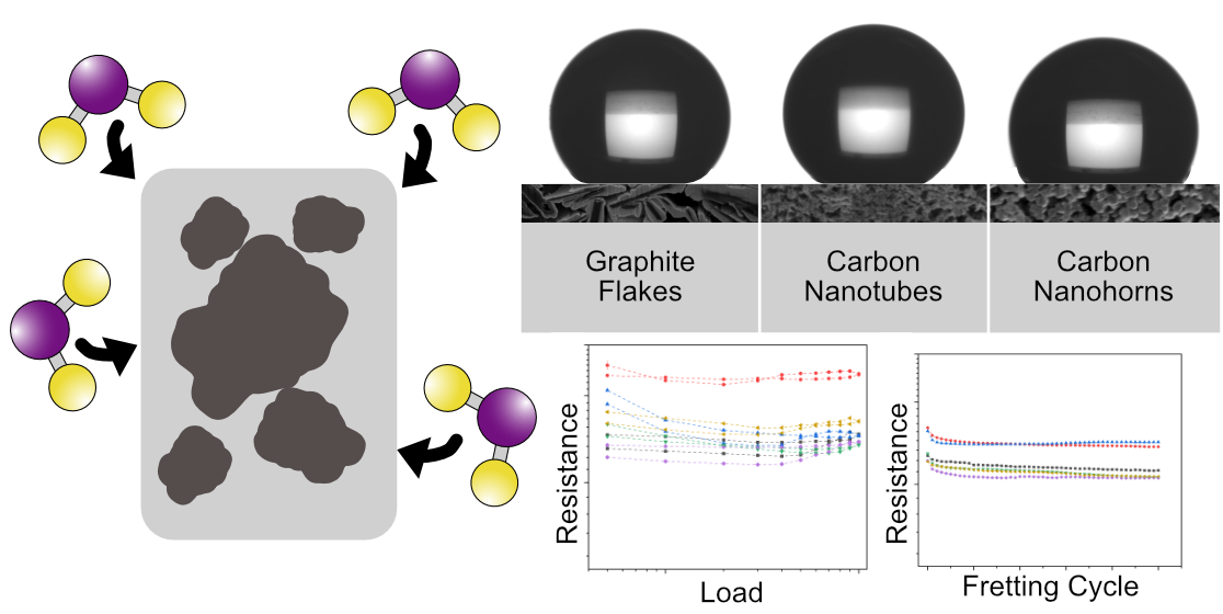
Comprehensive Study on Carbon-Coated Silver for Improved Tribo-Electrical and Wetting Performance

Department of Materials Science and Engineering, Saarland University, Campus D3.3, 66123 Saarbrücken, Germany
*
Author to whom correspondence should be addressed.
Submission received: 13 December 2023 / Revised: 18 January 2024 / Accepted: 1 February 2024 / Published: 4 February 2024

Abstract

:
The rise in electrification has considerably increased the demand for high-efficiency and durable electrical contact materials. Carbon nanoparticles (CNP) are a promising coating material due to their intrinsic transport properties (thus minimizing the impact on conductivity), their proven solid lubricity (potentially improving tribological performance), and their hydrophobic wetting behavior (potentially providing atmospheric protection). In this study, carbon nanotube and nanohorn coatings are produced via electrophoretic deposition on silver-plated surfaces, followed by tribo-electrical and wetting characterization. The proposed coatings do not negatively affect the conductivity of the substrate, showing resistance values on par with the uncoated reference. Tribo-electrical characterization revealed that the coatings reduce adhesive wear during fretting tests while maintaining stable and constant electrical contact resistance. Furthermore, CNP-coated surfaces show a hydrophobic wetting behavior toward water, with graphite and carbon nanotube (CNT) coatings approaching super-hydrophobicity. Prolonged exposure to water droplets during sessile drop tests caused a reduction in contact angle (CA) measurement; however, CNT coatings’ CA reduction after five minutes was only approximately 5°. Accordingly, CNP (specifically CNT) coatings show auspicious results for their application as wear and atmospheric protective barriers in electrical contacts.

Graphical Abstract

1. Introduction

Silver is very reputed as an electrical contact material not only due to its extraordinary conductivity but also due to its chemical stability. A key component in silver’s ubiquitous use in high-reliability connectors is that it does not oxidize. The lack of oxidation is advantageous since it precludes the formation of non-conductive or semi-conducting oxide films, as is the case with other commonly used contact materials (i.e., copper, tin, aluminum, etc.). Nonetheless, prolonged atmospheric exposure causes the formation of a semi-conductive silver sulfide (tarnishing) film—reaction shown in (1) [1,2,3,4,5,6,7,8,9,10,11,12]. Many methods have been developed to hinder or prevent this reaction, primarily in the form of protective coatings; however, alkanethiols have garnered the most widespread industrial adaptation [13,14,15,16]. The use of alkanethiols (e.g., hexadecanethiol and octadecanethiol, HDT and ODT, respectively) delays the formation of silver sulfide by saturating the silver surface with sulfhydryl groups. HDT and ODT consist of long chains of unsaturated oils where sulfhydryl groups bond with carbon terminals, thus allowing HDT and ODT to bond with transition metals. Sulfhydryl passivation forms Ag-S covalent bonds, forming a dense self-assembled monolayer, thus preventing atmospheric sulfur from reacting with the silver contact material by saturating the silver surface with the sulfur from the sulfhydryl groups [16]. However, the efficacy of these self-assembled monolayers is reliant on the orientation of the free-standing HDT or ODT tail. After the sulfhydryl group bonds with silver, the tail is free to rotate, allowing it to orient itself in an upstanding orderly position or lying on the silver surface in a disordered fashion. These monolayers are more efficient at preventing silver from tarnishing when the tails are oriented in an upstanding position due to increased thiol bonds with the substrate [16].
2 A g + S A g 2 S
Carbon nanoparticles (CNP) present a viable alternative to other passivation techniques which cannot only improve on the shortcomings of these techniques but could also present added advantages. Carbon nanostructures have excellent transport properties, a characteristic of utmost importance when dealing with electrical contact material [17,18,19,20,21,22]. Furthermore, nanocarbons present the advantage of outstanding lubricating capabilities, with extensive use as solid lubricants and lubricant oil additives [23,24,25,26,27,28,29,30,31,32].
Previous work carried out by Loyd et al. delineated the lubricating capabilities of graphite, graphene, and CNT specifically for their implementation in low-voltage and low-current applications [33]. Moreover, previous studies on CNP coatings over copper substrates have shown favorable results in terms of tribological and electrical performance, as well as for atmospheric protection due to the hydrophobic tendency of the CNP [34,35,36,37]. Therefore, it is the objective of this study to evaluate the impact, drawbacks, and advantages of CNP coatings on silver substrates. The CNP chosen for this analysis are carbon nanotubes (CNT) and carbon nanohorns (CNH), nanostructures that have shown the most promising results on copper substrates with regards to their effect on the system’s conductivity, as well as wear and atmospheric protection. However, since silver is used in demanding, high-reliability applications, and considering the significant financial investment that silver contacts incur, it is crucial to comprehensively understand the impact that CNP coatings could have on this outstanding conductor, as well as the benefits that could be gained from CNP-coated silver surfaces. In order to accurately appraise the feasibility of the proposed coatings, benchmarking samples were also evaluated. Accordingly, the CNT and CNH coatings were compared with a reference sample, a tarnished sample (i.e., a silver surface with a thin silver sulfide tarnishing film), and a sample coated with graphite flakes (GF). The proposed coatings were not only compared to a clean reference sample (optimal conductivity) but also to a tarnished sample (worsened conductivity) to gain complete insight into the performance of the CNT and CNH coatings within this conductivity spectrum. Furthermore, GF-coated samples serve as an industrially accepted benchmark (due to graphite’s solid lubricity and conductivity), which will better reflect on the feasibility and applicability of the proposed coatings.
Prior to characterization, all samples were chemically cleaned. The cleaned samples were subsequently tarnished or coated. The tarnishing process is a chemical process that involves subjecting the silver surfaces to a saturated sulfur atmosphere, thus rapidly generating a silver sulfide film on the sample’s surface. The coatings were produced via electrophoretic deposition (EPD). This method was chosen due to its simplicity, ease in controlling coating thicknesses, its ability to coat geometrically complex surfaces, as well as its scalability. All surfaces were tribo-electrically characterized via load-dependent electrical contact resistance (ECR) and static ECR development during fretting wear. Furthermore, roughness, coating thickness, and assessment of the fretting marks were carried out via confocal laser scanning microscopy (CLSM). The latter were additionally characterized via scanning electron microscopy (SEM) and energy dispersive X-ray spectroscopy (EDS) for extensive chemical analysis. Moreover, wetting behavior was characterized via sessile drop test using two different media: deionized water and a potassium sulfide-deionized water solution. These characterization techniques allow for an in-depth analysis of the impact on the system’s conductivity, as well as the potential wear and atmospheric protection provided by the CNP coatings in relation to the reference, tarnished, and GF-coated samples.

2. Materials and Methods

2.1. Sample Preparation

Three CNP coatings were the subject of this study (namely, GF, CNT, and CNH). The GF (Alfa Aesar GmbH, Kandel, Germany) have a median size between 7 and 10 µm a carbon purity of 99.8%. The CNT used were chemical vapor deposition-grown multi-walled CNT (Graphene Supermarket, New York, NY, USA). The as-received CNT have a length ranging from 10 to 15 µm, an outer diameter distribution between 50 and 85 nm, and a carbon purity over 94%. Furthermore, the CNH used are single-walled, dahlia-type nanostructures (Carbonium SRL, Brescia, Italy). These particles were produced without a catalyst by rapid condensation of carbon atoms, resulting in high carbon purity. Horn diameters range from 3 to 5 nm, with horn lengths from 30 to 50 nm and cluster diameters from 60 to 120 nm.
The substrates and reference material were silver-plated copper surfaces. A focused ion beam (FIB) cross-section was conducted (FEI Helios NanoLab600 Dual Beam Setup, Hillsboro, OR, USA) to determine the plating thickness. The cross-section revealed an average silver plating thickness of 4 µm, as well as a nickel interlayer between the silver and copper base material (see Figure S1). Due to the thinness of the silver plating, the samples were neither ground nor polished to avoid the removal of the plating material. Vickers hardness of the substrate was measured using a microhardness tester (Dura Scan 50, Struers Inc., Cleveland, OH, USA). A total of 35 indentations were carried out using a load of approximately 2 N and a holding time of 15 s. The imprints were optically observed using a 40× objective, resulting in an average hardness of 1.33 ± 0.04 GPa.
Accelerated corrosion (sulfidation) of the silver surfaces was carried out using the methodology proposed by Huo et al. [38]. This method consists of subjecting the silver surfaces to a saturated atmosphere of sulfur vapor. This methodology ensures a well-controlled and repeatable sulfur-rich atmosphere, which promotes and accelerates the formation of the silver sulfide tarnishing film. Therefore, an oversupply of sulfur powder (8 g) was placed in a ceramic container within a beaker. The vessel was covered with a watch glass and heated to 150 °C, thus evaporating the sulfur and saturating the atmosphere within the vessel. Thereupon the silver samples were placed inside the sulfur-rich atmosphere for 10 min. After the accelerated tarnishing process, the samples present a highly heterogeneous silver sulfide layer (see Figure S2). To ensure reproducibility, all tarnished samples used in this study were sulfurized simultaneously. Therefore, the degree to which the samples were tarnished did not significantly differ, thus guaranteeing similar behavior regardless of the sample that was used.
EPD was carried out at a constant voltage of 300 V (potentiostatic process) with an inter-electrode distance of 15 mm. Prior to the deposition process, the CNP must be dispersed in isopropyl alcohol by homogenization and ultrasound [35,36]. Triethylamine (C6H15N) was added to the colloid prior to dispersion. The use of this additive enhances the stability of the colloidal dispersion as well as providing the CNP with a superficial charge through the attachment of functional groups (i.e., positive charge, anodic deposition). The colloid, dispersion, and deposition parameters for all four sample types are detailed in Table S1 [35]. The four resulting coatings are a 10 min GF coating, a 5 min CNT coating, a 10 min CNT coating, and a 10 min CNH coating (henceforth GF10, CNT5, CNT10, and CNH10, respectively). To ensure consistent results, a fresh dispersion was prepared prior to each coating process. Consequently, the CNP’s concentration and dispersion quality of the colloid can also be considered constant. Although the use of other solvents (e.g., ethylene glycol) results in a more stable dispersion [39], isopropyl alcohol was chosen due to its lower viscosity. A solvent with lower viscosity will minimize viscous drag in the colloid, which will consequently minimize the CNP’s resistance toward electrophoresis, thus improving the deposition rate. Moreover, the lower vapor pressure of isopropyl alcohol guarantees fast and efficient drying of the coated samples after removal from the colloid.
Prior to EPD and accelerated tarnishing, the silver platelets were chemically cleaned to remove any passivating elements that were added (e.g., octadecanethiol) as a final step in the manufacturing process. The cleaning process consists of reducing the silver sulfide layer formed during passivation [40,41]. Removing any potential passivation elements on the samples’ surface ensures that maximum electrophoresis is achieved during EPD and that the accelerated tarnishing process is effective without requiring excessive exposure times. After chemical cleaning, the samples were thoroughly rinsed with deionized water, followed by ultrasonication in isopropyl alcohol for 5 min, thus removing potential residue from the cleaning process.

2.2. Characterization Techniques

The substrate, tarnished, and coated samples were micrographed via CLSM (OLS4100, Olympus, Tokyo, Japan). CLSM micrographs were acquired using 20× and 50× magnification and a laser wavelength of 405 nm. These micrographs were used to analyze the roughness of the samples (shown in Table 1) and coating thicknesses (shown in Table 2), as well as to qualitatively evaluate fretting marks on both electrodes. Furthermore, fretting marks were also micrographed via SEM (HeliosTM G4 PFIB CXe DualBeamTM Super FIB/SEM equipped with an energy dispersive X-ray spectroscopy detector EDAX Octane Elite Super, Thermo-Fisher Scientific, Eindhoven, The Netherlands) using ion conversion and electron (ICE) detector with an acceleration voltage of 5 kV. The same instrument was used to carry out chemical composition maps of the wear marks via EDS at an acceleration voltage of 15 kV. With this technique, a qualitative analysis of material transfer can be conducted. Furthermore, it can be used to determine if the wear resulting from the fretting tests was severe enough to reach the copper base material.
As the results from Table 2 show, the resulting coating thicknesses are relatively thin. Previous studies evaluating CNP-coated copper substrates using the same deposition technique produced considerably thicker coatings [35,37,42,43]. It was hypothesized that residue left behind by the chemical cleaning process might affect the conductivity of the silver samples, thus reducing the deposition rate of CNP onto their surfaces. To rule this possibility out, an as-received silver sample was coated—without prior cleaning—using the same parameters. The resulting coating thickness measured coincided with the samples that were chemically cleaned. The high roughness present in the silver samples could also play a role in the thinness of the coatings (260 nm against 10–20 nm in mirror-polished copper) since the electric field generated during EPD is concentrated at the asperities. The field’s concentration can thus disrupt and diminish the deposition rate of the CNP. However, this is unlikely to be the cause since it has been previously studied and reported that EPD has the capability to coat geometrically complex surfaces [44,45,46].
Wetting behavior was characterized by measuring the contact angle (CA) via sessile drop test using a drop shape analyzer (Krüss—DSA100B, Hamburg, Germany). A 3 µL droplet of deionized water and potassium sulfide (K2S) was placed onto the surfaces via a pipette. The volume of 3 µL suppresses gravitation distortion of the droplet’s shape and, at the same time, covers a sufficiently large area on the sample’s surface to even out topographical or chemical inhomogeneities [47,48]. The potassium sulfide solution consists of dissolving the compound in deionized water at a concentration of 3 wt.% at 23 °C (according to factory standard LK2070). Once each droplet was settled onto the sample’s surface, the CA was recorded by fitting its contour using an elliptical shape within the ADVANCE Software (version 1.14.3, Krüss, Germany). At least two droplets were measured per sample, measuring CA after 10, 30, 60, and 300 s. Measuring at different time intervals provides insight into the dynamic, time-resolved wetting performance of the surfaces in question and its reliance on the liquid media used during sessile drop test. All CA measurements were carried out at temperatures and humidity ranging from 19–20 °C and 24–26% RH, respectively.
Tribo-electrical characterization of the reference, tarnished, and CNP-coated samples was conducted using a custom testing rig [49]. Characterization was divided into two experimental methodologies: i.e., load-dependent ECR and ECR evolution during fretting test. Load-dependent ECR consisted of one loading and unloading cycle sourcing 100 mADC and measuring voltage drop between the electrodes (loading cycle: 0.5, 1, 2, 3, 4, 5, 6, 7, 8, 9, 10 N). This current level was chosen so that the measurement process does not cause microstructural modification of the contacting surfaces, thus affecting subsequent measurements (i.e., dry circuit conditions) [50]. In this loading range, a maximum Hertzian contact pressure of 230 and 623 MPa were achieved for 0.5 and 10 N, respectively. These values were determined using Hertzian contact theory for sphere-on-plane contact [51,52]. Fretting tests were carried out at a load of 1 N (maximum Hertzian contact pressure of 289 MPa), with an amplitude of 35 µm and an oscillation frequency of 8 Hz. A total of 5000 fretting cycles were conducted with periodic galvanostatic (100 mADC) ECR measurements carried out every 100 cycles (static ECR). All tribo-electrical tests were carried out using a Keithley 2400 source and a Keithley 2182a nanovoltmeter with a range of 0.1 V (Cleveland, OH, USA). In all cases, the voltage drop was recorded ten times and averaged, with each test being repeated at least three times to ensure reproducibility. Tribo-electrical characterization was conducted under ambient conditions, i.e., 21 ± 1 °C and 35 ± 5% RH. Since humidity plays an important role in the conductivity of CNT [44,53,54,55,56], all electrical measurements for each coating type were conducted on the same day. Therefore, errors in the measurements due to changes in atmospheric conditions were minimized.
The counter electrodes used for tribo-electrical characterization are silver-nickel core (AgNi0.15) and hard-gold-coated (AuCo0.2) rivets (Adam Bornbaum GmbH, Neuhausen, Germany). The hard-gold coating has an average thickness of 6.47 ± 0.18 µm. The rivets have a hemispherical head, with a mean radius of curvature at its tip of 4 mm, a root mean squared roughness of 0.26 µm (measured via CLSM), and a hardness of 1.38 ± 0.01 GPa (measured via Vickers microhardness). A new rivet was used for each measurement.

3. Results and Discussion

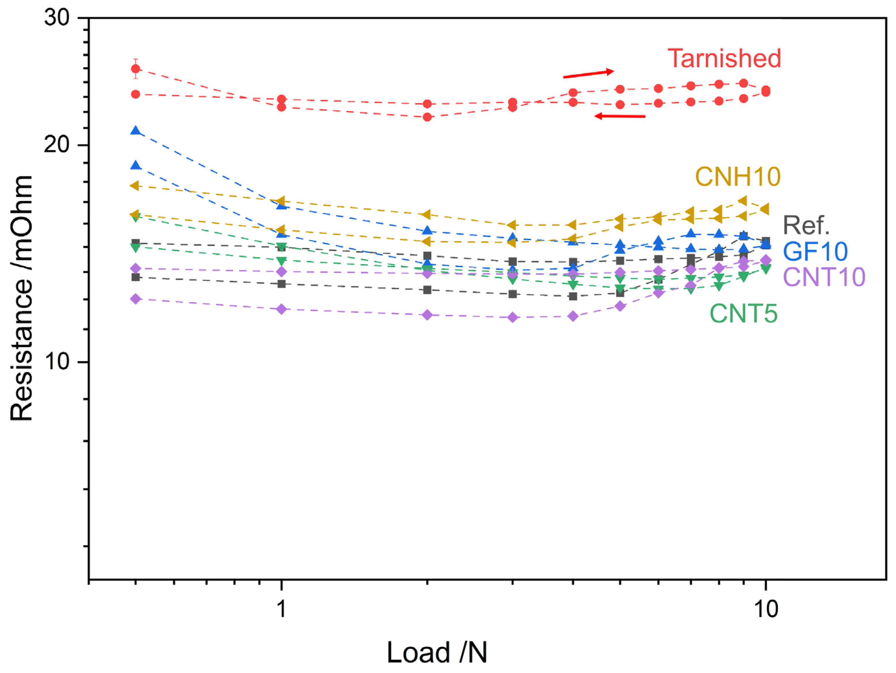
3.1. Load-Dependent ECR

Electrical characterization is an important component when considering coatings for electrical contacts since these layers play a pivotal role in the conductivity and overall efficiency of the connector. A key aspect that can be tailored during connector design is the contact load. Therefore, load-dependent ECR curves of the materials used provide crucial information for connector and connector housing design. The ECR curves for the reference, tarnished, and coated samples are shown in Figure 1. Immediately, it is clear that the tarnished sample stands out from the reference and coated samples. Throughout the loading range, the tarnished sample consistently shows ECR values above 20 mΩ, whereas the reference and coated samples show ECR values between 11 and 20 mΩ. It is interesting to highlight the variability in the ECR of the tarnished sample in the loading semi-cycle, whereas the ECR values are constant in the unloading semi-cycle. Between 0.5 N and 2 N, there is a sharp reduction in ECR. This is due to the puncturing of the silver sulfide tarnishing film by the counter electrode’s asperities [41,57]. However, as loads gradually increase (above 2 N), so does the ECR. The counter electrode’s geometry plays a role in this observation. As the load increases, the apparent contact diameter increases on account of the hemispherical shape of the rivets used. As the apparent contact area increases, so do the contacting sites between the counter electrode and the less-conductive (semi-conductive) tarnishing film, increasing the quasi-metallic contact [57,58]. The newly formed quasi-metallic contacts between the rivet’s lower asperities and the tarnished sample increase the predominance of the film resistance, thus playing a more crucial role in the overall electrical resistance of the system. For sufficiently high loads (from 4 N), however, the resistance of the film takes a less dominant role due to the puncturing of the film and well-established metallic contact between the counter electrode and the silver surface beneath the silver sulfide film. This results in the constant ECR measured from 4 N (in the loading semi-cycle) until the end of the measurement cycle. This behavior in the tarnished sample is solely caused by the puncturing of the tarnishing film since the sharp reduction in ECR is characteristic of this sample, with the clean silver sample not presenting this behavior. In other words, the asperities in contact with the silver sulfide film undergo additional constriction of the current, which is eased as the film is punctured by the individual asperities (between 0.5 and 2 N). The additional constriction of the current is a consequence of the higher resistivity of the tarnishing film compared with the resistivity of the bulk material. Between 2 N and 4 N, new quasi-metallic contacts are established between lower asperities and the tarnishing film, once again increasing constriction resistance’s dominance in the system. For loads above 4 N, most of the asperities have punctured the film, resulting in lower constriction resistance due to the current flowing from the counter electrode’s asperities toward the silver bulk material. Moreover, the current level used to measure ECR is sufficiently high to overcome the loss of ohmicity produced by not only the tarnishing film but also other contaminant films and the CNP coatings (current-dependent ECR curves shown in Figure S3).
The CNH coating shows the highest resistance among the coated samples, with the only exception being the GF coating at low loads. However, at 10 N, the ECR of CNH10 is only 2 mΩ higher than the reference sample at the same load. Therefore, the CNH coating does not significantly impact the electrical performance of the silver substrate. Nonetheless, the CNH coating is considerably thin (approximately 0.32 µm). Moreover, the CNH coating shows the most similarity in terms of ECR values between loading and unloading semi-cycle. This is due to the high elasticity of the coating, thus showing low electrical hysteresis. In this regard, the use of CNH coatings for electrical contacts could promote reproducible contact areas irrespective of the normal load applied while also mitigating topographic factors [48]. The high elasticity observed in CNH coatings is due to two factors: (1) the nanoparticles’ morphology and (2) the microporous network obtained by EPD. The former allows the CNT-like horns to deform inward from tip to base when undergoing compressive stress, thus enabling this nanostructure to return to its original shape after removing the compressive load (elastic restitution) [59]. This characteristic of the CNH justifies the low electrical hysteresis observed. The latter is a characteristic of the coatings obtained. The CNH coatings do not present large voids (as is the case with other CNP coatings) but rather a complex microporous network (see coating cross-section in [35]). This allows the voids to be rapidly closed during compaction with minimal CNH readjustment required, thus explaining the relatively constant ECR values measured during loading and unloading.
GF produces the thickest CNP coating; nonetheless, the resistance values are not severely impacted by the coating for loads above 1 N. Although the ECR values for the GF-coated sample are higher than the reference, the ECR coincide at 9 and 10 N. The CNT-coated samples, on the other hand, show exceptional electrical performance. The thinner CNT coating shows marginally higher ECR values than the reference sample; however, past 5 N CNT5 shows lower ECR. The thicker CNT coating outperformed the reference sample for the entire loading range, highlighting the promising potential of this coating type. The improved performance can be explained by two aspects: (1) the conductivity and (2) the elasticity of the CNT. These two aspects combined increase the real contact area between the counter electrode and the sample. The increased conductivity of the nanotubes, in conjunction with their elasticity, enables more pathways for electron motion between the two electrodes. In other words, although the apparent contact area may be the same, the highly elastic CNT coating increases the real contact area between the electrodes, thus reducing the ECR. Since CNT5 is thinner than CNT10, this phenomenon does not occur initially, thus requiring higher loads to establish an adequate electrical contact between the nanotubes and the counter electrode. Furthermore, the CNT tend to adhere to the counter electrode after loading, which also promotes lower electrical hysteresis and overall ECR (CLSM micrographs of counter electrodes post-ECR are shown in Figure S4).

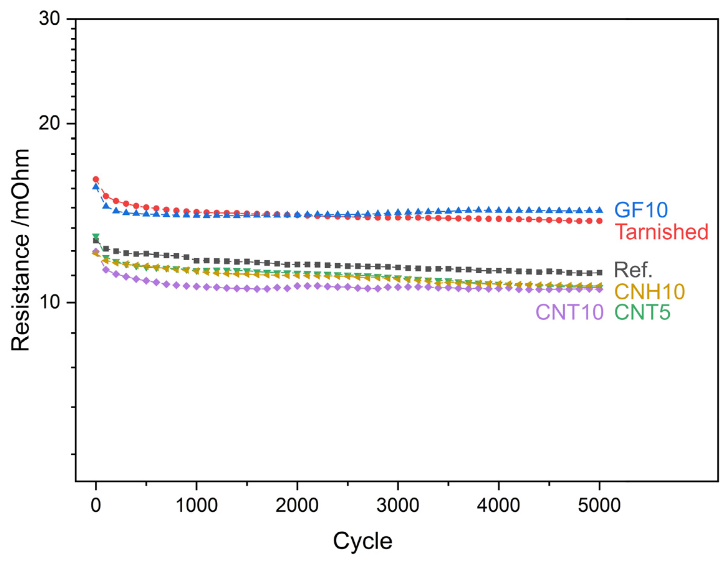
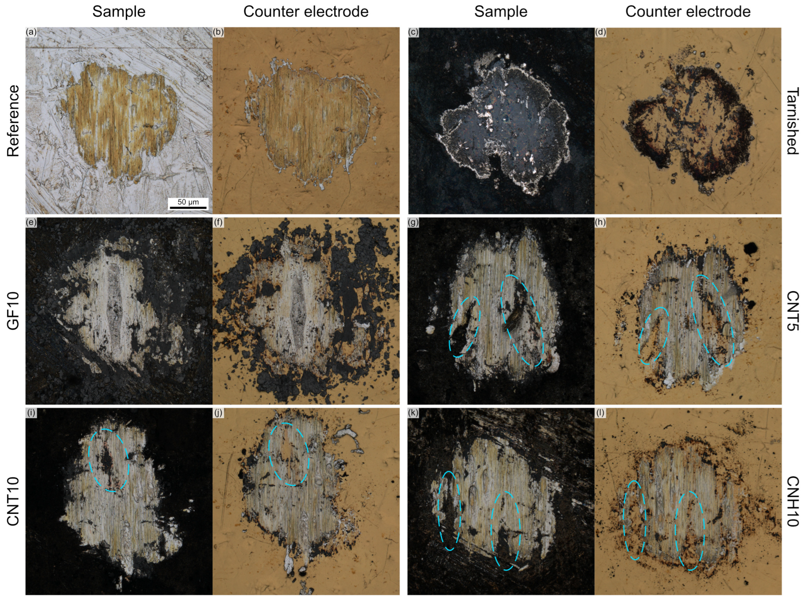
3.2. ECR Evolution during Fretting Test

Tribo-electrical characterization aims to determine the effectiveness of the proposed coatings at reducing wear with negligible influence on ECR. Consequently, tracking the evolution of ECR as fretting cycles progress is of utmost importance. The results are shown in Figure 2. The plot depicts that irrespective of the sample type, all samples showed higher ECR initially and a slight reduction as fretting cycles progressed. However, this was to be expected since prior to fretting, the ECR is a combination of the film resistance (contaminant film, tarnishing film, or the coating itself), constriction resistance, and bulk material resistance. After the fretting test begins, contaminant films are constantly being broken down. Therefore, the resistance after the initial fretting cycles is primarily due to constriction resistance and the bulk material’s resistance. Particularly in the case of the coated samples, the CNP are displaced due to the fretting motion, which reduces the amount of CNP present at the contacting site, thus marginally reducing ECR [42,43]. It is noteworthy to highlight, however, that the ECR values after the first few hundred fretting cycles are highly stable for all samples. In other words, there are no abrupt fluctuations in ECR due to fretting. This could be related to the fact that silver and gold do not form oxide films (as opposed to other metals, e.g., copper). It could also be related to the generation of a stable conductive carbonaceous tribofilm, which stabilizes the interface. Figure 2 exhibits that two distinct groupings took place. Namely, the tarnished and GF-coated samples present higher ECR during fretting than the reference, CNT, and CNH-coated samples. As was the case with load-dependent ECR (Figure 1), both CNT coatings outperformed the reference sample. CNT5 initially has a slightly higher ECR than the reference sample. However, after the first one hundred fretting cycles, it quickly falls below the values observed in the reference sample. CNT10, on the other hand, has a lower ECR throughout the measurement. The CNH coating, nonetheless, also outperformed the reference sample during fretting tests with an electrical performance similar to that of CNT5, albeit this could be caused by the heterogeneous nature of the EPD coatings and should not be over-interpreted.
Post-fretting micrographs of the marks left behind on the samples and counter electrodes are shown in Figure 3. In the reference sample, a considerable amount of material was transferred from the counter electrode toward the sample (Figure 3a), whereas marginal amounts of silver were transferred toward the counter electrode (Figure 3b). Silver debris is found primarily in the perimeter of the fretting marks and, to a minor extent, within the gross slip regions in the center of the fretting mark [60]. Gold is only observed adhered onto the sample’s surface without gold debris surrounding the fretting marks. Bidirectional material transfer was expected during wear tests since the silver sample and the hard-gold counter electrode have similar hardness values (less than 10% difference—1.33 and 1.38 GPa, respectively) [60]. The tarnished sample fretting mark (Figure 3c,d) strongly contrasts the wear track observed in the reference sample. Although both fretting marks are approximately the same size, the mark on the tarnished sample does not have adhered gold. Furthermore, the counter electrode that contacted the tarnished sample shows minimal silver debris particles. The lack of material transfer can be explained by the lubricating capacity of the silver sulfide tarnishing film, albeit the lubricating capacity of the tarnishing film does not significantly reduce worn area [41]. Nonetheless, the presence of the tarnishing film strongly reduces gross slip, with both the sample and the counter electrode showing minimal wear. Furthermore, black particles observed in the counter electrode are silver sulfide particles that adhered during tribological testing.
The micrographs of the GF-coated sample (Figure 3e,f) depict that considerable gross slip took place in the central region of the fretting mark (in both the sample and the counter electrode). This is likely due to the ease of GF displacement and the detachment of the GF coating. Nonetheless, as shown in Figure 3f, large amounts of detached GF particles adhered to the counter electrode (lower-right region of the fretting mark in Figure 3e,f). Consequently, minimal amounts of GF remain within the fretting mark, therefore reducing this coating’s capacity to reduce wear. CNT and CNH-coated samples’ fretting marks (Figure 3g–i) highly contrast with GF-coated samples. These coatings do not show significant displacement or detachment. Consequently, after 5000 fretting cycles, there are regions within the fretting marks that still have CNP which provide protection from wear (regions highlighted by cyan ovals in CLSM micrographs). Consequently, the CNPs within the fretting mark protect from wear, as proven by the enclosed region in the counter electrodes (i.e., regions where partial slip or no damage took place). Moreover, traces of CNT and CNH adhered to the counter electrode, further promoting wear protection. However, the amounts of transferred CNT and CNH are negligible compared to the quantity of GF that was transferred.
A key distinction between the reference sample and the CNP-coated samples is the permutation of the dominant transfer electrode. In other words, the former shows that gold was predominantly transferred from the counter electrode toward the silver sample, whereas the latter shows that silver was predominantly transferred from the sample toward the counter electrode. Silver was not transferred in the form of debris (there are minimal amounts of silver debris present in the CNP-coated samples), but rather, silver adhered to the gold counter electrode. The material transfer observed during fretting is caused by adhesive wear, in other words, cold welding. After initial wear, contaminant films are removed from both surfaces (silver and gold). As fretting cycles progress, the elimination of the contaminant films enables the adhesion of the two metals [61]. However, the presence of carbon in the coated samples reduces the microscopic temperature of the asperities in the silver sample due to the outstanding thermal conductivity of the CNP. Furthermore, the carbon coating effectively separates the two contacting surfaces, reducing the likelihood of metal-metal contact but rather generating a contacting site constituted of metal-carbon-metal. Therefore, it is reasonable to infer that the permutation of the deposition electrode is caused by the increased temperature in the counter electrode and a consequent reduction on the silver surfaces. This hypothesis is further supported by the lack of material transfer observed in the tarnished sample (Figure 3c,d). Since the silver sulfide tarnishing film lubricates the contact site, gold adhesion did not take place in the silver sample, whereas small silver debris particles can be seen in the counter electrode’s micrographs surrounding the fretting mark.
To further analyze the mechanism behind material transfer, EDS mappings were carried out. The EDS maps are shown in Figure 4, with the corresponding secondary electron micrograph shown in Figure S5 and the sulfur EDS map of the tarnished sample shown in Figure S6. The EDS maps confirm that gold was transferred from the counter electrode towards the CNP-coated silver samples. Although EDS is a qualitative technique, it is accurate to state that the presence of the CNP coatings reduces the amount of gold transferred onto the samples due to the lack of gold signal detected within the fretting marks in spots where carbon and/or silver signals are stronger. Furthermore, the EDS maps of the tarnished sample (Figure 4b) also confirm that the lubricating capacity of the silver sulfide layer prevents the adhesion of gold. Moreover, the EDS maps prove that after 5000 fretting cycles, the base material was not reached in any of the samples analyzed. Although copper was detected within the fretting mark in the CNT5 sample (Figure 4d), the areas enclosed by the white dashed lines showcase that the plating material’s thickness throughout the samples is heterogeneous. Consequently, there are regions (unaffected by fretting wear) where the copper base material was detected via EDS. Therefore, the copper detected within the fretting mark in CNT5 cannot be attributed to a lack of wear protection from the coating but rather heterogeneity in the plating process.

3.3. Wetting Behavior

Water contact angle measurements were carried out to evaluate the wetting behavior of the reference, tarnished, and CNP-coated surfaces (Figure 5). All surfaces show a hydrophobic wetting behavior within five minutes of placing the water droplet. Nonetheless, the reference sample shows a marginally hydrophobic behavior, with stable CA values of approximately 100° within the first minute. After five minutes, however, the CA decreases to approximately 92°, thus showing borderline hydrophobicity. The tarnished sample initially shows a higher CA; however, the value quickly decreases as time passes, reaching 90° after five minutes. GF and CNT show a strong hydrophobic behavior, approaching superhydrophobic wetting behavior after prolonged droplet exposure. CNH also shows high CA values; however, its performance does not reach as high CA as GF and CNT. The slightly stronger affinity toward water from CNH can be caused by the particle’s morphology. Due to the dahlia-type nanostructures, the nanohorns have a strong strain-induced curvature, which delocalizes the high mobility π orbitals, thus increasing this nanostructure’s reactivity and consequently affecting its wetting behavior [62]. Nonetheless, CNH coatings produced via EPD generate a coating with a complex microporous network [35]. Therefore, despite the reactivity of the CNH, coating morphology prevents the penetration of the water droplet, consequently producing a surface-droplet interface that resembles a Cassie-Baxter wetting state. Based on a previous study, thicker CNH coatings do not significantly impact its wetting behavior [43]. Therefore, even for thin CNH coatings, the microporous network is quickly established and is effective at preventing droplet infiltration.
GF shows near-superhydrophobic wetting behavior; however, after five minutes, the CA decreases by approximately 10°. This reduction indicates that the water droplet is slowly infiltrating the coating, primarily due to pores on the surface of the coating. Notwithstanding, the complexity of the porous network within the coating retains the hydrophobic wetting behavior of the GF-coated surface, resembling the performance observed for the CNH-coated surface. On the other hand, both CNT coatings show, to a certain extent, stable CA values within the timeframe evaluated. After five minutes of setting the droplet onto the CNT surfaces, the CA decreases by approximately 5° as opposed to over 10° in the GF- and CNH-coated surfaces. This performance highlights the hydrophobic nature of the nanotubes, with thicker coatings showing a tendency toward marginally higher CA. Therefore, prolonging the deposition process (and thus obtaining a thicker coating) could promote super-hydrophobicity in the CNT-coated surfaces. Moreover, a smoother substrate could further increase the CA, improving hydrophobicity [63]. Additionally, Korczeniewski et al. previously reported that larger CNT agglomerate reduces CA, however, prolonging dispersion times (homogenization and ultrasound) negatively impacts the structure of the nanotubes [39,64]. The damage incurred by the CNT (in the form of dangling bonds, among other structural defects) could prove counterproductive by increasing the nanostructure’s reactivity, thus reducing its CA.
Based on the wetting behavior observed with water droplets, it was of interest to evaluate the effectiveness of the coatings with a harsher medium (i.e., potassium sulfide). As was done with deionized water, 3 µL of the potassium sulfide solution was pipetted onto the six surfaces (CA results shown in Figure 6). However, the CNP-coated surfaces did not prevent the infiltration of the solution. The droplet rapidly penetrated the coatings and dispersed over the surfaces, producing CA below 40°. The GF showed an improved performance compared to the reference and tarnished samples. After 10 s, GF showed a CA of approximately 60°. However, the CA rapidly decreased to approximately 50° after 60 S and below 40° after 5 min. Nonetheless, this is a higher CA of 10–20° after five minutes of exposure to the highly aggressive potassium sulfide solution.
Although the wetting results obtained when measuring CA with potassium sulfide do not suggest a favorable outcome, it should be noted that the solution is an extreme case used to analyze the potential protection offered by the carbon coatings. In other words, this is an accelerated method used to simulate prolonged exposure to sulfur-rich atmospheres. As previously studied, nanocarbon coatings show exceptional wetting behavior when measuring CA with other media than water (i.e., salt water) [43]. Therefore, the results from the potassium sulfide tests should be used to fully dismiss the potential use cases of carbon coatings, particularly GF.

4. Conclusions

In this work, silver-plated electrical connectors were coated with CNT and CNH. The tribo-electrical and wetting performance of these coatings was compared to reference, tarnished (corroded), and GF-coated samples. Load-dependent electrical contact resistance proves that the presence of thin CNP films does not hinder the efficiency of the connectors. CNT-coated samples showed exceptional electrical performance, with similar ECR values to that of the reference sample throughout the entirety of the loading ranges analyzed. Although CNH and GF presented slightly higher ECR values than the reference, these two coatings did not increase the resistance as significantly as the corrosion film (silver sulfide tarnishing film). Likewise, the tarnished sample showed poor electrical performance during fretting wear tests. The tarnishing film, however, protects the silver surface from severe wear, minimizing adhesive wear and gross slip. The CNP-coated surfaces reduced material transfer during fretting while maintaining consistently low ECR. However, coating displacement hinders wear protection (primarily affecting GF coatings). Certain regions of the CNT and CNH-coated samples (and counter electrode) were protected from severe fretting wear due to the presence of these nanostructures within the contacting site after 5000 fretting cycles. Moreover, the CNP-coated surfaces exhibit a hydrophobic (near-superhydrophobic in the case of GF and CNT) wetting behavior in sessile drop tests measured using deionized water, outperforming the tarnished and reference samples. Prolonged water droplet exposures tend to decrease the CA measured; however, the reduction in CA for the CNT-coated samples is significantly lower than in the other surfaces studied. Moreover, the CA measurements with potassium sulfide indicated that although CNT and CNH do not offer significant protection, GF coatings did show higher CA than the reference and tarnished samples, even after five minutes of exposure. Nonetheless, it should be reiterated that the medium used (i.e., potassium sulfide) is extremely aggressive and was chosen based on the fact that this solution would simulate prolonged exposure to sulfur-rich atmospheres.
This study features the exceptional characteristics of nanocarbon coatings and their potential benefits for the electrical contact industry. However, further studies are required to improve on the aspects presented in this work. Namely, improving wear and atmospheric protection without impacting electrical performance. The former may be improved by evaluating different EPD additives that improve coating adhesion (e.g., magnesium nitrate), thus reducing coating displacement during wear tests. The latter, on the other hand, may benefit from chemical alterations of the CNP (e.g., CNP decoration), consequently tailoring the reactivity of the nanostructures for specific atmospheric conditions.

Supplementary Materials

The following supporting information can be downloaded at: https://www.mdpi.com/article/10.3390/c10010016/s1, Figure S1: FIB cross section of silver-plated copper electrical contact. The platinum layer was deposited using the SEM with the purpose of protecting the sample and to minimize the curtaining effect during ion milling; Figure S2: Silver sample (a) before and (b) after being subjected to sulfur-rich atmosphere. Highlighted regions show SEM micrographs of the surface before and after the accelerated tarnishing process; Table S1: Colloid, dispersion, and EPD parameters; Figure S3: Current-dependent ECR of references, tarnished, and coated samples; Figure S4: CLSM micrograph of counter electrodes after ECR measurements of (a) reference, (b) tarnished, (c) GF10, (d) CNT5, (e) CNT10, and (f) CNH10 sample; Figure S5: Secondary electron micrograph of fretting marks after 5000 cycles of (a) reference sample, (b) tarnished sample, (c) GF10, (d) CNT5, (e) CNT10, and (f) CNH10. Micrographs (a) and (b) were acquired at 15 kV due to the presence of surface contaminants, whereas the rest were acquired at 5 kV acceleration voltage; Figure S6: EDS map of the fretting mark after 5000 cycles in the tarnished sample showing the signal for sulfur.

Author Contributions

Conceptualization, B.A. and S.S.; Data curation, B.A.; Formal analysis, B.A.; Funding acquisition, F.M. and S.S.; Investigation, B.A.; Methodology, B.A. and S.S.; Project administration, F.M. and S.S.; Resources, F.M.; Supervision, S.S.; Validation, B.A.; Visualization, B.A.; Writing—original draft, B.A.; Writing—review and editing, S.S. All authors have read and agreed to the published version of the manuscript.

Funding

This research received no external funding.

Data Availability Statement

Data available upon reasonable request from the corresponding author.

Acknowledgments

B. Alderete wishes to acknowledge the support from the German Academic Exchange Service (DAAD) and the Roberto Rocca Education Program (RREP). The authors gratefully acknowledge funding in the ZuMat project, supported by the State of Saarland from the European Regional Development Fund (Europäischen Fonds für Regionale Entwicklung, EFRE). Funding for the PFIB/SEM instrument by the German Research Foundation is greatly acknowledged (INST 256/510-1 FUGG).

Conflicts of Interest

The authors declare no conflict of interest.

References

  1. Outka, D.A.; Madix, R.J.; Fisher, G.B.; DiMaggio, C. Oxidation of Sulfur Dioxide on Silver (110): Vibrational Study of the Structure of Intermediate Complexes Formed. J. Phys. Chem. 1986, 90, 4051–4057. [Google Scholar] [CrossRef]
  2. Bauer, R. Sulfide Corrosion of Silver Contacts during Satellite Storage. J. Spacecr. Rocket. 1988, 25, 439–440. [Google Scholar] [CrossRef]
  3. Lilienfeld, S.; White, C.E. A Study of the Reaction between Hydrogen Sulfide and Silver. J. Am. Chem. Soc. 1930, 52, 885–892. [Google Scholar] [CrossRef]
  4. Russ, G. Electrical Characteristics of Contacts Contaminated with Silver Sulfide Film. IEEE Trans. Parts Mater. Packag. 1970, 6, 129–137. [Google Scholar] [CrossRef]
  5. Hindin, B.S. Silver Sulfide Corrosion Control Using Corrosion Prevention Compounds. In Proceedings of the CORROSION 2006, San Diego, CA, USA, 12–16 March 2006; p. NACE-06264. [Google Scholar]
  6. Denaburg, C.R. Corrosion in Aerospace Electrical/Electronic Components in the Early Years of the Apollo Program, Kennedy Space Center, Florida. In Proceedings of the CORROSION 2000, Orlando, FL, USA, 26–31 March 2000; p. NACE-00718. [Google Scholar]
  7. Schmitt, W.; Franz, S.; Heber, J.; Lutz, O.; Behrens, V. Formation of Silver Sulfide Layers and Their Influence on the Electrical Characteristics of Contacts in the Field of Information Technology. In Proceedings of the ICEC, Innsbruck, Austria, 19–22 August 2008; pp. 489–494. [Google Scholar]
  8. Wagner, C. Investigations on Silver Sulfide. J. Chem. Phys. 1953, 21, 1819–1827. [Google Scholar] [CrossRef]
  9. Hebb, M.H. Electrical Conductivity of Silver Sulfide. J. Chem. Phys. 1952, 20, 185–190. [Google Scholar] [CrossRef]
  10. Sahraoui, K.; Benramdane, N.; Khadraoui, M.; Miloua, R.; Mathieu, C. Characterization of Silver Sulphide Thin Films Prepared by Spray Pyrolysis Using a New Precursor Silver Chloride. Sens. Transducers 2014, 27, 319–325. [Google Scholar]
  11. Zhang, S.; Osterman, M.; Shrivastava, A.; Kang, R.; Pecht, M.G. The Influence of H2S Exposure on Immersion-Silver-Finished PCBs under Mixed-Flow Gas Testing. IEEE Trans. Device Mater. Reliab. 2010, 10, 71–81. [Google Scholar] [CrossRef]
  12. Abbott, W.H. The Development and Performance Characteristics of Mixed Flowing Gas Test Environment. IEEE Trans. Compon. Hybrids Manuf. Technol. 1988, 11, 22–35. [Google Scholar] [CrossRef]
  13. Ying, T. An Advanced Anti-Tarnish Process for Silver Coins and Silverware—Monomolecular Octadecanethiol Protective Film. Tribol. Trans. 2021, 64, 341–349. [Google Scholar] [CrossRef]
  14. Liang, C.; Yang, C.; Huang, N. Tarnish Protection of Silver by Octadecanethiol Self-Assembled Monolayers Prepared in Aqueous Micellar Solution. Surf. Coat. Technol. 2009, 203, 1034–1044. [Google Scholar] [CrossRef]
  15. Liang, C.H.; Yang, C.J.; Huang, N.B.; Wu, B. Comparison of Four Antitarnishing Self-Assembled Monolayers on Silver Coin. Surf. Eng. 2011, 27, 199–204. [Google Scholar] [CrossRef]
  16. Phillips, A.C.; Cowley, A. Octadecanthiol for Tarnish-Resistant Silver Coatings. In Proceedings of the Modern Technologies in Space- and Ground-Based Telescopes and Instrumentation II, Amsterdam, The Netherlands, 1–6 July 2012; Navarro, R., Cunningham, C.R., Prieto, E., Eds.; Volume 8450, p. 84503W. [Google Scholar]
  17. Planes, E.; Flandin, L.; Alberola, N. Polymer Composites Bipolar Plates for PEMFCs. Energy Procedia 2012, 20, 311–323. [Google Scholar] [CrossRef]
  18. Saito, R.; Dresselhaus, G.; Dresselhaus, M.S. Physical Properties of Carbon Nanotubes; Imperial College Press: London, UK, 1998; ISBN 978-1-86094-093-4. [Google Scholar]
  19. Dresselhaus, M.S.; Dresselhaus, G.; Saito, R. Physics of Carbon Nanotubes. Carbon 1995, 33, 883–891. [Google Scholar] [CrossRef]
  20. Popov, V. Carbon Nanotubes: Properties and Application. Mater. Sci. Eng. R Rep. 2004, 43, 61–102. [Google Scholar] [CrossRef]
  21. Ebbesen, T.W. Carbon Nanotubes. Annu. Rev. Mater. Sci. 1994, 24, 235–264. [Google Scholar] [CrossRef]
  22. Nasir, S.; Hussein, M.; Zainal, Z.; Yusof, N. Carbon-Based Nanomaterials/Allotropes: A Glimpse of Their Synthesis, Properties and Some Applications. Materials 2018, 11, 295. [Google Scholar] [CrossRef] [PubMed]
  23. Lee, C.-G.; Hwang, Y.-J.; Choi, Y.-M.; Lee, J.-K.; Choi, C.; Oh, J.-M. A Study on the Tribological Characteristics of Graphite Nano Lubricants. Int. J. Precis. Eng. Manuf. 2009, 10, 85–90. [Google Scholar] [CrossRef]
  24. Zhang, Z.; Simionesie, D.; Schaschke, C. Graphite and Hybrid Nanomaterials as Lubricant Additives. Lubricants 2014, 2, 44–65. [Google Scholar] [CrossRef]
  25. Cornelio, J.A.C.; Cuervo, P.A.; Hoyos-Palacio, L.M.; Lara-Romero, J.; Toro, A. Tribological Properties of Carbon Nanotubes as Lubricant Additive in Oil and Water for a Wheel–Rail System. J. Mater. Res. Technol. 2016, 5, 68–76. [Google Scholar] [CrossRef]
  26. Dassenoy, F.; Joly-Pottuz, L.; Martin, J.M.; Mieno, T. Carbon Nanotubes as Advanced Lubricant Additives. In Carbon Nanotubes; Popov, V.N., Lambin, P., Eds.; Kluwer Academic Publishers: Dordrecht, The Netherlands, 2006; pp. 237–238. [Google Scholar]
  27. Kałużny, J.; Merkisz-Guranowska, A.; Giersig, M.; Kempa, K. Lubricating Performance of Carbon Nanotubes in Internal Combustion Engines—Engine Test Results for CNT Enriched Oil. Int. J. Automot. Technol. 2017, 18, 1047–1059. [Google Scholar] [CrossRef]
  28. Maharaj, D.; Bhushan, B.; Iijima, S. Effect of Carbon Nanohorns on Nanofriction and Wear Reduction in Dry and Liquid Environments. J. Colloid. Interface Sci. 2013, 400, 147–160. [Google Scholar] [CrossRef]
  29. Sethi, S.; Dhinojwala, A. Superhydrophobic Conductive Carbon Nanotube Coatings for Steel. Langmuir 2009, 25, 4311–4313. [Google Scholar] [CrossRef]
  30. Rahman, M.M.; Islam, M.; Roy, R.; Younis, H.; AlNahyan, M.; Younes, H. Carbon Nanomaterial-Based Lubricants: Review of Recent Developments. Lubricants 2022, 10, 281. [Google Scholar] [CrossRef]
  31. De Nicola, F.; Castrucci, P.; Scarselli, M.; Nanni, F.; Cacciotti, I.; Crescenzi, M. De Super-Hydrophobic Multi-Walled Carbon Nanotube Coatings for Stainless Steel. Nanotechnology 2015, 26, 145701. [Google Scholar] [CrossRef] [PubMed]
  32. Chen, X.; Li, J. Superlubricity of Carbon Nanostructures. Carbon 2020, 158, 1–23. [Google Scholar] [CrossRef]
  33. Loyd, A.; Hemond, J.; Martens, R. A Preliminary Investigation of Graphite, Graphene and Carbon Nanotubes (CNT’s) as Solid State Lubricants. In Proceedings of the 2011 IEEE 57th Holm Conference on Electrical Contacts (Holm), Minneapolis, MN, USA, 11–14 September 2011; IEEE: Piscataway, NJ, USA, 2011; pp. 1–9. [Google Scholar]
  34. Reinert, L.; Varenberg, M.; Mücklich, F.; Suárez, S. Dry Friction and Wear of Self-Lubricating Carbon-Nanotube-Containing Surfaces. Wear 2018, 406–407, 33–42. [Google Scholar] [CrossRef]
  35. Alderete, B.; Mücklich, F.; Suarez, S. Characterization and Electrical Analysis of Carbon-Based Solid Lubricant Coatings. Carbon Trends 2022, 7, 100156. [Google Scholar] [CrossRef]
  36. Alderete, B.; MacLucas, T.; Espin, D.; Brühl, S.P.; Mücklich, F.; Suarez, S. Near Superhydrophobic Carbon Nanotube Coatings Obtained via Electrophoretic Deposition on Low-Alloy Steels. Adv. Eng. Mater. 2021, 23, 2001448. [Google Scholar] [CrossRef]
  37. Alderete, B.; Lößlein, S.M.; Bucio Tejeda, D.; Mücklich, F.; Suarez, S. Feasibility of Carbon Nanoparticle Coatings as Protective Barriers for Copper—Wetting Assessment. Langmuir 2022, 38, 15209–15219. [Google Scholar] [CrossRef]
  38. Huo, Y.; Fu, S.-W.; Chen, Y.-L.; Lee, C.C. A Reaction Study of Sulfur Vapor with Silver and Silver–Indium Solid Solution as a Tarnishing Test Method. J. Mater. Sci. Mater. Electron. 2016, 27, 10382–10392. [Google Scholar] [CrossRef]
  39. Reinert, L.; Zeiger, M.; Suárez, S.; Presser, V.; Mücklich, F. Dispersion Analysis of Carbon Nanotubes, Carbon Onions, and Nanodiamonds for Their Application as Reinforcement Phase in Nickel Metal Matrix Composites. RSC Adv. 2015, 5, 95149–95159. [Google Scholar] [CrossRef]
  40. Philadelphia Museum of Art Finishing Techniques in Metalwork—Hands-Free Silver “Polishing”. Available online: https://www.philamuseum.org/booklets/7_44_85_1.html?page=2 (accessed on 18 January 2021).
  41. Alderete, B.; Mücklich, F.; Suarez, S. Tarnishing (Ag2S) Layer on Silver-Plated Electrical Contacts: Its Influence on Electrical Contact Resistance. IEEE Trans. Compon. Packag. Manuf. Technol. 2023, 13, 45–58. [Google Scholar] [CrossRef]
  42. Alderete, B.; Mücklich, F.; Suarez, S. Wear Reduction via CNT Coatings in Electrical Contacts Subjected to Fretting. Tribol. Lett. 2023, 71, 54. [Google Scholar] [CrossRef]
  43. Alderete, B.; Suarez, S.; Tejeda, D.B.; Mücklich, F. Fretting and Electrical Contact Resistance Characteristics of Carbon Nanoparticle-Coated Cu Electrical Contacts. In Proceedings of the 2022 IEEE 67th Holm Conference on Electrical Contacts (HLM), Tampa, FL, USA, 23–26 October 2022; IEEE: Piscataway, NJ, USA, 2022; pp. 1–8. [Google Scholar]
  44. Thomas, B.J.C.; Boccaccini, A.R.; Shaffer, M.S.P. Multi-Walled Carbon Nanotube Coatings Using Electrophoretic Deposition (EPD). J. Am. Ceram. Soc. 2005, 88, 980–982. [Google Scholar] [CrossRef]
  45. Boccaccini, A.R.; Cho, J.; Roether, J.A.; Thomas, B.J.C.; Jane Minay, E.; Shaffer, M.S.P. Electrophoretic Deposition of Carbon Nanotubes. Carbon 2006, 44, 3149–3160. [Google Scholar] [CrossRef]
  46. Alderete, B.; Nayak, U.P.; Mücklich, F.; Suarez, S. Influence of Topography on Electrical Contact Resistance of Copper-Based Materials. Surf. Topogr. 2023, 11, 025027. [Google Scholar] [CrossRef]
  47. Vafaei, S.; Podowski, M.Z. Theoretical Analysis on the Effect of Liquid Droplet Geometry on Contact Angle. Nucl. Eng. Des. 2005, 235, 1293–1301. [Google Scholar] [CrossRef]
  48. Krainer, S.; Hirn, U. Contact Angle Measurement on Porous Substrates: Effect of Liquid Absorption and Drop Size. Colloids Surf. A Physicochem. Eng. Asp. 2021, 619, 126503. [Google Scholar] [CrossRef]
  49. Alderete, B.; Puyol, R.; Slawik, S.; Espin, E.; Mücklich, F.; Suarez, S. Multipurpose Setup Used to Characterize Tribo-Electrical Properties of Electrical Contact Materials. MethodsX 2021, 8, 101498. [Google Scholar] [CrossRef] [PubMed]
  50. Bock, E.M. Low-Level Contact Resistance Characterization. AMP J. Technol. 1993, 3, 64–68. [Google Scholar]
  51. Johnson, K.L. Contact Mechanics; Cambridge University Press: Cambridge, UK, 1987; ISBN 0521347963. [Google Scholar]
  52. Callister, W.D., Jr. Materials Science and Engineering: An Introduction, 7th ed.; John Wiley & Sons, Ltd.: Hoboken, NJ, USA, 2006; Volume 94, ISBN 9780470054888. [Google Scholar]
  53. Shooshtari, M.; Salehi, A.; Vollebregt, S. Effect of Humidity on Gas Sensing Performance of Carbon Nanotube Gas Sensors Operated at Room Temperature. IEEE Sens. J. 2021, 21, 5763–5770. [Google Scholar] [CrossRef]
  54. Tsai, J.T.H.; Lu, C.-C.; Li, J.G. Fabrication of Humidity Sensors by Multi-Walled Carbon Nanotubes. J. Exp. Nanosci. 2010, 5, 302–309. [Google Scholar] [CrossRef]
  55. Lee, Y.; Yoon, J.; Kim, Y.; Kim, D.M.; Kim, D.H.; Choi, S.-J. Humidity Effects According to the Type of Carbon Nanotubes. IEEE Access 2021, 9, 6810–6816. [Google Scholar] [CrossRef]
  56. Ling, Y.; Gu, G.; Liu, R.; Lu, X.; Kayastha, V.; Jones, C.S.; Shih, W.-S.; Janzen, D.C. Investigation of the Humidity-Dependent Conductance of Single-Walled Carbon Nanotube Networks. J. Appl. Phys. 2013, 113, 024312. [Google Scholar] [CrossRef]
  57. Holm, R. Electric Contacts, 4th ed.; Springer: Berlin/Heidelberg, Germany, 1967; ISBN 978-3-642-05708-3. [Google Scholar]
  58. Endres, H. Praxishandbuch Steckverbinder, 2nd ed.; Vogel COmmunications Group: Würzburg, Germany, 2021; ISBN 978-3-8343-3501-2. [Google Scholar]
  59. Karousis, N.; Suarez-Martinez, I.; Ewels, C.P.; Tagmatarchis, N. Structure, Properties, Functionalization, and Applications of Carbon Nanohorns. Chem. Rev. 2016, 116, 4850–4883. [Google Scholar] [CrossRef] [PubMed]
  60. Slade, P.G. Electrical Contacts, 2nd ed.; Slade, P.G., Ed.; CRC Press: Boca Raton, FL, USA, 2014; ISBN 9781315216829. [Google Scholar]
  61. Merstallinger, A.; Sales, M.; Semerad, E.; Dunn, B.D. Assessment of Cold Welding between Separable Contact Surfaces Due to Impact and Fretting under Vacuum. ESA Sci. Tech. Memo. 2009, 279, 57. [Google Scholar]
  62. Haddon, R.C. Chemistry of the Fullerenes: The Manifestation of Strain in a Class of Continuous Aromatic Molecules. Science 1993, 261, 1545–1550. [Google Scholar] [CrossRef]
  63. Korczeniewski, E.; Zięba, M.; Zięba, W.; Kolanowska, A.; Bolibok, P.; Kowalczyk, P.; Wiertel-Pochopień, A.; Zawała, J.; Boncel, S.; Terzyk, A.P. Electrophoretic Deposition of Layer-by-Layer Unsheathed Carbon Nanotubes—A Step Towards Steerable Surface Roughness and Wettability. Materials 2020, 13, 595. [Google Scholar] [CrossRef]
  64. Hilding, J.; Grulke, E.A.; George Zhang, Z.; Lockwood, F. Dispersion of Carbon Nanotubes in Liquids. J. Dispers. Sci. Technol. 2003, 24, 1–41. [Google Scholar] [CrossRef]
Figure 1. Load-dependent ECR of reference, tarnished, and coated samples. The arrows indicate the direction in which the loading and unloading semi-cycles progress.
Carbon 10 00016 g001
Figure 2. Evolution of ECR as fretting cycles progress of reference, tarnished, and coated samples. Note: error in all ECR measurements below ±0.2 mΩ.
Carbon 10 00016 g002
Figure 3. CLSM micrograph after 5000 fretting cycles of reference (a) sample and (b) counter electrode, tarnished (c) sample and (d) counter electrode, GF10 (e) sample and (f) counter electrode, CNT5 (g) sample and (h) counter electrode, CNT10 (i) sample and (j) counter electrode, and CNH10 (k) sample and (l) counter electrode. Cyan dashed line highlights regions in the sample where CNP remain within the fretting mark and their corresponding region in the counter electrode where only partial slip took place rather than gross slip.
Carbon 10 00016 g003
Figure 4. EDS elemental maps of (a) reference, (b) tarnished, (c) GF10, (d) CNT5, (e) CNT10, and (f) CNH10 samples. The left image shows an overlay of carbon (red) and gold (yellow), whereas the right image shows an overlay of silver (turquoise) and copper (orange). The regions enclosed by the dashed lines are regions unaffected by fretting wear where the copper base material was detected.
Carbon 10 00016 g004
Figure 5. Water contact angle measurements 10 s (orange), 30 s (green), 60 s (violet), and 300 s (yellow) after placing the droplets onto the surfaces. To the left, the macrographs of a droplet on each surface and the baseline (red) are shown. The shaded regions highlight the surfaces with hydrophobic (gray) and superhydrophobic (green) wetting behavior.
Carbon 10 00016 g005
Figure 6. Contact angle measurements 10 s (orange), 30 s (green), 60 s (violet), and 300 s (yellow) after placing a 3 µL droplet of K2S 3 wt.% solution onto the surfaces. To the left, the macrographs of a droplet on each surface and the baseline (red) are shown. Due to the hydrophilic wetting behavior, it was not possible to measure CA after 300 s in CNT5 and CNT10. Only CA after 10 s could be measured in CNH10.
Carbon 10 00016 g006
Table 1. Root mean squared roughness of samples, measured using CLSM.
SurfaceRoughness/µm
Reference0.26 ± 0.03
Tarnished0.40 ± 0.04
GF101.40 ± 0.12
CNT50.91 ± 0.16
CNT100.62 ± 0.02
CNH100.51 ± 0.01
Table 2. Coating thicknesses measured via CLSM.
CoatingThickness/µm
GF100.34 ± 0.10
CNT50.14 ± 0.04
CNT100.41 ± 0.05
CNH100.32 ± 0.08
Disclaimer/Publisher’s Note: The statements, opinions and data contained in all publications are solely those of the individual author(s) and contributor(s) and not of MDPI and/or the editor(s). MDPI and/or the editor(s) disclaim responsibility for any injury to people or property resulting from any ideas, methods, instructions or products referred to in the content.

