
Comparison of the Flow around Circular and Rectangular Emergent Cylinders with Subcritical and Supercritical Conditions
Abstract
:1. Introduction
2. Materials and Methods
2.1. Experimental Facility
2.2. Instrumentation and Flow Observations
2.3. Dimensional Analysis
2.3.1. Single Emergent Cylinder
2.3.2. Side-by-Side Two-Sided and Four-Sided Emergent Cylinder Arrays
3. Results and Discussion
3.1. Subcritical Flow through an Emergent Cylinder
3.2. Supercritical Flow through Emergent Cylinders
3.2.1. Supercritical Flow over the Sloping Channel Bed
3.2.2. Supercritical Flow over the Horizontal Channel Bed
3.3. Variation in the Depth of the Flow through the Side-by-Side Cylinder Array
3.4. Development of the Conceptual Models and Explanation of the Flow Transition
3.4.1. Single Emergent Cylinders in the Supercritical Flow
3.4.2. Side-by-Side Emergent Cylinder Array in the Supercritical Flow
4. Summary
5. Conclusions
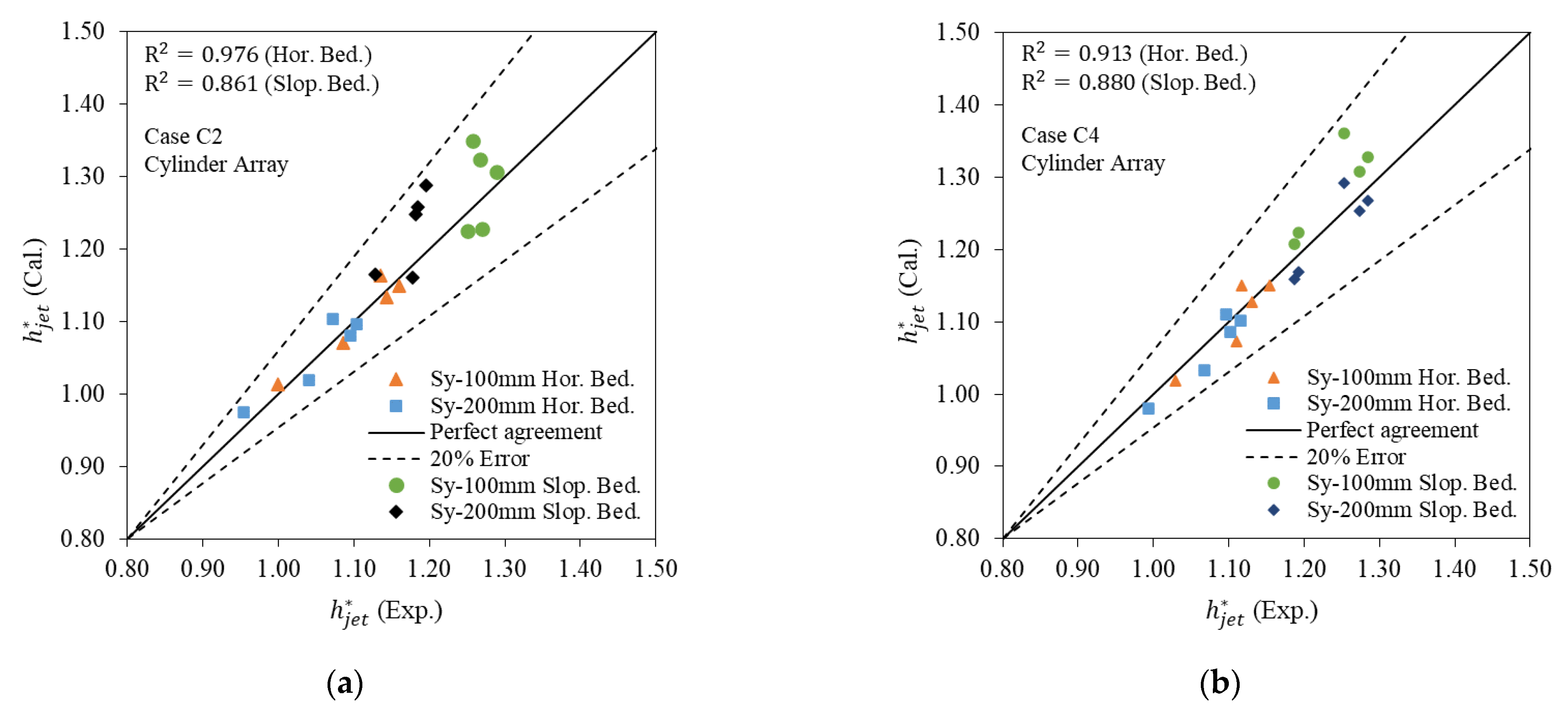
- The height of the wall-jet () was altered with the changes in the (or ) ratio in case C1 and with the changes in the ratio in the side-by-side cylinder arrays (cases C2 and C4) for both the supercritical conditions considered;
- The scale effects did not influence the wall-jet height () in the laboratory-scale experiment, and the extended droplets observed at the wall jets’ tips due to the capillary effect also did not affect the time-averaged wall-jet height;
- For the supercritical flows, when the (or ) ratio was > 1, a wall-jet-like bow-wave could develop in front of the obstacle. Furthermore, when the (or ) ratio was <1, a distinct detached hydraulic jump could occur in front of the obstacle with different geometrical characteristics;
- For the supercritical flow, the flow depth could increase within the side-by-side square cylinder array (case C4) in relation to the x and y directional spacing in the cylinder array and the sloping characteristics of the experimental flume;
- The derived equations were used to predict the non-dimensional wall-jet height with the supercritical flow over the single and side-by-side cylinder arrays, which can be helpful in designing piloti-type building structures in urban coastal environments as a resilience measure against future tsunami risks.
Author Contributions
Funding
Institutional Review Board Statement
Informed Consent Statement
Data Availability Statement
Acknowledgments
Conflicts of Interest
References
- Suppasri, A.; Mas, E.; Koshimura, S.; Imai, K.; Harada, K.; Imamura, F. Developing Tsunami Fragility Curves from the Surveyed Data of the 2011 Great East Japan Tsunami in Sendai and Ishinomaki Plains. Coast. Eng. J. 2012, 54, 1250008-1–1250008-16. [Google Scholar] [CrossRef]
- Okumura, N.; Jonkman, S.N.; Esteban, M.; Hofland, B.; Shibayama, T. A Method for Tsunami Risk Assessment: A Case Study for Kamakura, Japan. Nat. Hazards 2017, 88, 1451–1472. [Google Scholar] [CrossRef] [Green Version]
- Dissanayaka, K.D.C.R.; Tanaka, N.; Vinodh, T.L.C. Integration of Eco-DRR and Hybrid Defense System on Mitigation of Natural Disasters (Tsunami and Coastal Flooding): A Review. Nat. Hazards 2021, 110, 1–28. [Google Scholar] [CrossRef]
- Fadly, U.; Murakami, K. Study on Reducing Tsunami Inundation Energy by the Modification of Topography Based on Local Wisdom. J. Jpn. Soc. Civ. Eng. Ser. B3 Ocean Eng. 2012, 68, I_66–I_71. [Google Scholar] [CrossRef] [Green Version]
- Yoshiya, I.; Norio, T. Evaluation of the Effect of Level 2 Tsunami on Reducing Energy Based on Changes in Flow Conditions When Overflowing a Double Levee Structure. J. Jpn. Soc. Civ. Eng. B1 Hydraul. Eng. 2017, 73, I_1009–I_1014. [Google Scholar] [CrossRef]
- Kimiwada, Y.; Tanaka, N.; Zaha, T. Differences in Effectiveness of a Hybrid Tsunami Defense System Comprising an Embankment, Moat, and Forest in Submerged, Emergent, or Combined Conditions. Ocean Eng. 2020, 208, 107457. [Google Scholar] [CrossRef]
- Zaha, T.; Tanaka, N.; Kimiwada, Y. Flume Experiments on Optimal Arrangement of Hybrid Defense System Comprising an Embankment, Moat, and Emergent Vegetation to Mitigate Inundating Tsunami Current. Ocean Eng. 2019, 173, 45–57. [Google Scholar] [CrossRef]
- Teh, S.Y.; Koh, H.L.; Liu, P.L.; Ismail, A.I.M.; Lee, H.L. Analytical and Numerical Simulation of Tsunami Mitigation by Mangroves in Penang, Malaysia. J. Asian Earth Sci. 2009, 36, 38–46. [Google Scholar] [CrossRef]
- Rahman, M.M.; Schaab, C.; Nakaza, E. Experimental and Numerical Modeling of Tsunami Mitigation by Canals. J. Waterw. Port Coast. Ocean Eng. 2017, 143, 04016012. [Google Scholar] [CrossRef]
- Ryo, M.; Gozo, T.; Fumihiko, Y. A Study on Scouring by Overflow from Seawall and Application of an Artificial Trench. J. Jpn. Soc. Civ. Eng. Ser B2 Coast. Eng. 2013, 69, I_791–I_795. [Google Scholar] [CrossRef] [Green Version]
- Tokida, K.; Tanimoto, R. Lessons for Countermeasures Using Earth Structures against Tsunami Obtained in the 2011 Off the Pacific Coast of Tohoku Earthquake. Soils Found. 2014, 54, 523–543. [Google Scholar] [CrossRef]
- Tsujimoto, G.; Mineura, R.; Yamada, F.; Kakinoki, T.; Uno, K. Scouring Mechanism Behind Seawall from Tsunami Overflow and Optimum Conditions to Reduce Tsunami Energy with an Artificial Trench. Coast. Eng. Proc. 2014, 1, 38. [Google Scholar] [CrossRef] [Green Version]
- Strusińska-Correia, A. Tsunami Mitigation in Japan after the 2011 Tōhoku Tsunami. Int. J. Disaster Risk Reduct. 2017, 22, 397–411. [Google Scholar] [CrossRef]
- Rashedunnabi, A.H.M.; Tanaka, N. Energy Reduction of a Tsunami Current through a Hybrid Defense System Comprising a Sea Embankment Followed by a Coastal Forest. Geosciences 2019, 9, 247. [Google Scholar] [CrossRef] [Green Version]
- Dissanayaka, K.D.C.R.; Tanaka, N.; Hasan, M.K. Effect of Orientation and Vegetation over the Embankment Crest for Energy Reduction at Downstream. Geosciences 2022, 12, 354. [Google Scholar] [CrossRef]
- Tanaka, N. Effectiveness and Limitations of Coastal Forest in Large Tsunami: Conditions of Japanese Pine Trees on Coastal Sand Dunes in Tsunami Caused by Great East Japan Earthquake. J. Jpn. Soc. Civ. Eng. Ser. B1 Hydraul. Eng. 2012, 68, II_7–II_15. [Google Scholar] [CrossRef] [PubMed] [Green Version]
- Tanaka, N. Vegetation Bioshields for Tsunami Mitigation: Review of Effectiveness, Limitations, Construction, and Sustainable Management. Landsc. Ecol. Eng. 2009, 5, 71–79. [Google Scholar] [CrossRef] [Green Version]
- Tanaka, D.S.; Istiyanto, D.D.C.; Kuribayashi, M.D. Planning and Design of Tsunami-Mitigative Coastal Vegetation Belts; ICHARM Publ. No18, Technical note of PWRI no. 4177; International Centre for Water Hazard and Risk Management, United Nations Educational, Scientific and Cultural Organization: Paris, France, 2010.
- Cuomo, G.; Shams, G.; Jonkman, S.; van Gelder, P. Hydrodynamic Loadings of Buildings in Floods. In Coastal Engineering 2008; World Scientific Publishing Company: Singapore, 2009; pp. 3744–3756. ISBN 978-981-4277-36-5. [Google Scholar]
- Cox, D.; Tomita, T.; Lynett, P.; Holman, R. Tsunami Inundation with Macro-Roughness in the Constructed Environment. In Coastal Engineering 2008; World Scientific Publishing Company: Singapore, 2009; pp. 1421–1432. ISBN 978-981-4277-36-5. [Google Scholar]
- Goseberg, N. Reduction of Maximum Tsunami Run-up due to the Interaction with Beachfront Development—Application of Single Sinusoidal Waves. Nat. Hazards Earth Syst. Sci. 2013, 13, 2991–3010. [Google Scholar] [CrossRef] [Green Version]
- Park, H.; Cox, D.T.; Lynett, P.J.; Wiebe, D.M.; Shin, S. Tsunami Inundation Modeling in Constructed Environments: A Physical and Numerical Comparison of Free-Surface Elevation, Velocity, and Momentum Flux. Coast. Eng. 2013, 79, 9–21. [Google Scholar] [CrossRef]
- Manawasekara, C.; Mizutani, N.; Aoki, S. Influence of Openings and Orientation on Tsunami Generated Forces on Buildings. J. Disaster Res. 2016, 11, 670–679. [Google Scholar] [CrossRef]
- Chock, G.; Robertson, I.; Kriebel, D.; Francis, M.; Nistor, I. Tohoku, Japan, Earthquake and Tsunami of 2011; American Society of Civil Engineers: Reston, VA, USA, 2013; ISBN 978-0-7844-1249-7. [Google Scholar]
- American Society of Civil Engineers. Minimum Design Loads for Buildings and Other Structures; American Society of Civil Engineers: Reston, VA, USA, 2013; ISBN 978-0-7844-1291-6. [Google Scholar]
- Lukkunaprasit, P.; Ruangrassamee, A. Tsunami Loading on Buildings with Openings. Sci. Tsunami Hazards 2009, 28, 303–310. [Google Scholar]
- Mikami, T.; Shibayama, T.; Esteban, M.; Takabatake, T.; Nakamura, R.; Nishida, Y.; Achiari, H.; Rusli; Marzuki, A.G.; Marzuki, M.F.H.; et al. Field Survey of the 2018 Sulawesi Tsunami: Inundation and Run-up Heights and Damage to Coastal Communities. Pure Appl. Geophys. 2019, 176, 3291–3304. [Google Scholar] [CrossRef]
- Honda, T.; Oda, Y.; Ito, K.; Watanabe, M.; Takabatake, T. An Experimental Study on the Tsunami Pressure Acting on the Piloti-Type Buildings. Coast. Eng. Proc. 2014, 34, 41. [Google Scholar] [CrossRef]
- Yamamoto, T.; Kazama, S.; Touge, Y.; Yanagihara, H.; Tada, T.; Yamashita, T.; Takizawa, H. Evaluation of Flood Damage Reduction throughout Japan from Adaptation Measures Taken under a Range of Emissions Mitigation Scenarios. Clim. Chang. 2021, 165, 60. [Google Scholar] [CrossRef]
- Dang-Vu, H.; Shin, J.; Lee, K. Seismic Fragility Assessment of Columns in a Piloti-Type Building Retrofitted with Additional Shear Walls. Sustainability 2020, 12, 6530. [Google Scholar] [CrossRef]
- Benjamin, T.B. On the Flow in Channels When Rigid Obstacles Are Placed in the Stream. J. Fluid Mech. 1956, 1, 227–248. [Google Scholar] [CrossRef]
- Mignot, E.; Riviere, N. Bow-Wave-like Hydraulic Jump and Horseshoe Vortex around an Obstacle in a Supercritical Open Channel Flow. Phys. Fluids 2010, 22, 117105. [Google Scholar] [CrossRef] [Green Version]
- Mignot, E.; Moyne, T.; Doppler, D.; Riviere, N. Clear-Water Scouring Process in a Flow in Supercritical Regime. J. Hydraul. Eng. 2016, 142, 04015063. [Google Scholar] [CrossRef] [Green Version]
- Raju, K.G.R.; Rana, O.P.S.; Asawa, G.L.; Pillai, A.S.N. Rational Assessment of Blockage Effect in Channel Flow Past Smooth Circular Cylinders. J. Hydraul. Res. 1983, 21, 289–302. [Google Scholar] [CrossRef]
- Riviere, N.; Vouaillat, G.; Launay, G.; Mignot, E. Emerging Obstacles in Supercritical Open-Channel Flows: Detached Hydraulic Jump versus Wall-Jet-like Bow Wave. J. Hydraul. Eng. 2017, 143, 04017011. [Google Scholar] [CrossRef] [Green Version]
- Samarasekara, R.S.M.; Sasaki, J.; Esteban, M.; Matsuda, H. Assessment of the Co-Benefits of Structures in Coastal Areas for Tsunami Mitigation and Improving Community Resilience in Sri Lanka. Int. J. Disaster Risk Reduct. 2017, 23, 80–92. [Google Scholar] [CrossRef]
- Potts, D.A. Hydrodynamics of Vertical Surface-Piercing Cylinders. Master’s Thesis, University of Tasmania, Tasmania, Australia, 2019. [Google Scholar]
- Lam, K.; Zou, L. Experimental Study and Large Eddy Simulation for the Turbulent Flow around Four Cylinders in an In-Line Square Configuration. Int. J. Heat Fluid Flow 2009, 30, 276–285. [Google Scholar] [CrossRef]
- Wang, X.K.; Gong, K.; Liu, H.; Zhang, J.-X.; Tan, S.K. Flow around Four Cylinders Arranged in a Square Configuration. J. Fluids Struct. 2013, 43, 179–199. [Google Scholar] [CrossRef]
- Sumner, D.; Wong, S.S.T.; Price, S.J.; Païdoussis, M.P. Fluid Behaviour of Side-by-Side Circular Cylinders in Steady Cross-Flow. J. Fluids Struct. 1999, 13, 309–338. [Google Scholar] [CrossRef]
- Waniewski, T.A.; Brennen, C.E.; Raichlen, F. Bow Wave Dynamics. J. Ship Res. 2002, 46, 1–15. [Google Scholar] [CrossRef]
- McDonald, A.K. Experimental Investigation of Small-Scale Breaking Waves: Flow Visualization across the Air-Water Interface; Massachusetts Institute of Technology: Cambridge, MA, USA, 2005. [Google Scholar]
- Elhanafi, A.; Duffy, J.; Macfarlane, G.; Binns, J.; Keough, S.J. Inline Forces and Bow Wave Height on a Vertical Cylinder Moving in Waves—Experimental Study and CFD Validation. J. Fluids Struct. 2021, 107, 103387. [Google Scholar] [CrossRef]
- Yarnell, D.L. Bridge Piers as Channel Obstructions; USDA: Washington, DC, USA, 1934; Volume 52, p. 8.
- Synolakis, C.E.; Kong, L. Runup Measurements of the December 2004 Indian Ocean Tsunami. Earthq. Spectra 2006, 22, 67–91. [Google Scholar] [CrossRef]
- Goff, J.; Liu, P.L.-F.; Higman, B.; Morton, R.; Jaffe, B.E.; Fernando, H.; Lynett, P.; Fritz, H.; Synolakis, C.; Fernando, S. Sri Lanka Field Survey after the December 2004 Indian Ocean Tsunami. Earthq. Spectra 2006, 22, 155–172. [Google Scholar] [CrossRef]
- Yeh, H.; Sato, S. Tsunami Effects on Buildings and Coastal Structures. J. Disaster Res. 2016, 11, 662–669. [Google Scholar] [CrossRef]
- Tappin, D.R.; Evans, H.M.; Jordan, C.J.; Richmond, B.; Sugawara, D.; Goto, K. Coastal Changes in the Sendai Area from the Impact of the 2011 Tōhoku-Oki Tsunami: Interpretations of Time Series Satellite Images, Helicopter-Borne Video Footage and Field Observations. Sediment. Geol. 2012, 282, 151–174. [Google Scholar] [CrossRef]
- Peakall, J.; Warburton, J. Surface Tension in Small Hydraulic River Models—The Significance of the Weber Number. J. Hydrol. N. Z. 1996, 35, 199–212. [Google Scholar]
- Arnaud, G.; Rey, V.; Touboul, J.; Sous, D. Wave Propagation Through Dense Vertical Cylinder Arrays: 3D Experimental Study. Int. J. Ocean Coast. Eng. 2019, 2, 1950001. [Google Scholar] [CrossRef] [Green Version]
- Zdravkovich, M.M. Conceptual Overview of Laminar and Turbulent Flows Past Smooth and Rough Circular Cylinders. J. Wind Eng. Ind. Aerodyn. 1990, 33, 53–62. [Google Scholar] [CrossRef]
- Graf, W.H.; Altinakar, M.S. A Review of “Hydraulique Fluviale Ecoulement Permanent Uniforme et Non Uniforme”. Eur. J. Eng. Educ. 1994, 19, 378–379. [Google Scholar] [CrossRef]
- Wüthrich, D.; Pfister, M.; Nistor, I.; Schleiss, A.J. Experimental Study on the Hydrodynamic Impact of Tsunami-like Waves against Impervious Free-Standing Buildings. Coast. Eng. J. 2018, 60, 180–199. [Google Scholar] [CrossRef]
- Nandasena, N.A.K.; Sasaki, Y.; Tanaka, N. Modeling Field Observations of the 2011 Great East Japan Tsunami: Efficacy of Artificial and Natural Structures on Tsunami Mitigation. Coast. Eng. 2012, 67, 1–13. [Google Scholar] [CrossRef]
- Qi, Z.X.; Eames, I.; Johnson, E.R. Force Acting on a Square Cylinder Fixed in a Free-Surface Channel Flow. J. Fluid Mech. 2014, 756, 716–727. [Google Scholar] [CrossRef] [Green Version]
- Dias, P.; Dissanayake, R.; Chandratilake, R. Lessons Learned from Tsunami Damage in Sri Lanka. Proc. Inst. Civ. Eng. Civ. Eng. 2006, 159, 74–81. [Google Scholar] [CrossRef]


| Description | Value | |
|---|---|---|
| Diameter of the circular cylinder (mm) | 32, 47, 60 | |
| Width of the rectangular cylinder (mm) | 30, 20 | |
| Water depth (mm) (subcritical) | 30.7, 37.0, 45.5, 49.1, 55.7 | 0.59, 0.63, 0.65, 0.67, 0.70 |
| Water depth (mm) (supercritical with a 1/200 bed slope) | 20.5, 26.7, 30.7, 38.1, 44.2 | 1.27, 1.37, 1.40, 1.41, 1.45 |
| Water depth (mm) (supercritical with zero bed slope) | 53.2, 45.5, 38.0, 30.7, 23.5 | 1.45, 1.52, 1.70, 1.74, 1.99 |
| Case | Case Name |
|---|---|
| Case C1-CC | Single emergent circular cylinder |
| Case C1-RC | Single emergent rectangular cylinder |
| Case C2-1 | Side-by-side two-cylinder array (center-to-center spacing was 200 mm) |
| Case C2-2 | Side-by-side two-cylinder array (center-to-center spacing was 100 mm) |
| Case C4-1 | Side-by-side four-cylinder array (spacings of were 100 mm and 100 mm) |
| Case C4-2 | Side-by-side four-cylinder array (spacings of were 200 mm and 200 mm) |
| 32 mm dia. | 47 mm dia. | 60 mm dia. | 30 × 40 mm | 20 × 20 mm | |
|---|---|---|---|---|---|
| 0.59 | 0.56 | 0.42 | 0.37 | 0.91 | 1.03 |
| 0.63 | 0.57 | 0.49 | 0.42 | 1.07 | 1.18 |
| 0.65 | 0.70 | 0.55 | 0.50 | 1.25 | 1.30 |
| 0.67 | 0.79 | 0.58 | 0.52 | 1.37 | 1.43 |
| 0.70 | 0.87 | 0.69 | 0.61 | 1.54 | 1.53 |
| Non-Dimensional Property | Upstream Water Depth —1/200 Sloping Channel Bed (mm) | Cylinder Dimension | ||||
|---|---|---|---|---|---|---|
| 20.5 | 26.7 | 30.7 | 38.1 | 44.2 | ||
| 0.45 | 0.53 | 0.68 | 0.65 | 0.74 | 32 mm dia. | |
| 0.31 | 0.37 | 0.45 | 0.52 | 0.58 | 47 mm dia. | |
| 0.32 | 0.33 | 0.39 | 0.48 | 0.59 | 60 mm dia. | |
| 0.69 | 0.81 | 0.93 | 1.08 | 1.11 | 30 × 40 mm | |
| 0.83 | 0.92 | 1.07 | 1.20 | 1.39 | 20 × 20 mm | |
| 0.64 | 0.93 | 1.33 | 1.29 | 1.47 | 32 mm dia. | |
| 0.39 | 0.62 | 0.73 | 0.91 | 0.96 | 47 mm dia. | |
| 0.33 | 0.49 | 0.60 | 0.73 | 0.81 | 60 mm dia. | |
| 0.63 | 0.97 | 1.15 | 1.36 | 1.57 | 30 × 40 mm | |
| 1.01 | 1.52 | 1.62 | 2.12 | 2.45 | 20 × 20 mm | |
| Non-Dimensional Property | Upstream Water Depth —1/200 Sloping Channel Bed (mm) | Case | |||||
|---|---|---|---|---|---|---|---|
| 20.5 | 26.7 | 30.7 | 38.1 | 44.2 | |||
| 0.17 | 0.19 | 0.22 | 0.24 | 0.26 | C2-1 | 100 | |
| 0.21 | 0.33 | 0.37 | 0.48 | 0.58 | |||
| 0.07 | 0.09 | 0.10 | 0.12 | 0.13 | C2-2 | 200 | |
| 0.13 | 0.17 | 0.19 | 0.26 | 0.32 | |||
| 0.17 | 0.18 | 0.20 | 0.23 | 0.26 | C4-1 | 100 | |
| 0.19 | 0.33 | 0.37 | 0.50 | 0.61 | |||
| 0.08 | 0.10 | 0.12 | 0.13 | 0.14 | C4-2 | 200 | |
| 0.11 | 0.18 | 0.21 | 0.27 | 0.33 | |||
| Non-Dimensional Property | Upstream Water Depth —1/200 Sloping Channel Bed (mm) | Cylinder Dimension | ||||
|---|---|---|---|---|---|---|
| 23.5 | 30.7 | 38.0 | 45.5 | 53.2 | ||
| 2.92 | 2.19 | 1.88 | 1.48 | 1.29 | 32 mm dia. | |
| 3.23 | 2.39 | 2.16 | 1.72 | 1.46 | 47 mm dia. | |
| 3.48 | 2.66 | 2.28 | 1.79 | 1.50 | 60 mm dia. | |
| 2.94 | 2.16 | 1.91 | 1.47 | 1.26 | 30 × 40 mm | |
| 2.43 | 1.82 | 1.61 | 1.24 | 1.06 | 20 × 20 mm | |
Disclaimer/Publisher’s Note: The statements, opinions and data contained in all publications are solely those of the individual author(s) and contributor(s) and not of MDPI and/or the editor(s). MDPI and/or the editor(s) disclaim responsibility for any injury to people or property resulting from any ideas, methods, instructions or products referred to in the content. |
© 2023 by the authors. Licensee MDPI, Basel, Switzerland. This article is an open access article distributed under the terms and conditions of the Creative Commons Attribution (CC BY) license (https://creativecommons.org/licenses/by/4.0/).
Share and Cite
Dissanayaka, K.D.C.R.; Tanaka, N. Comparison of the Flow around Circular and Rectangular Emergent Cylinders with Subcritical and Supercritical Conditions. Fluids 2023, 8, 124. https://doi.org/10.3390/fluids8040124
Dissanayaka KDCR, Tanaka N. Comparison of the Flow around Circular and Rectangular Emergent Cylinders with Subcritical and Supercritical Conditions. Fluids. 2023; 8(4):124. https://doi.org/10.3390/fluids8040124
Chicago/Turabian StyleDissanayaka, Kannangara D. C. R., and Norio Tanaka. 2023. "Comparison of the Flow around Circular and Rectangular Emergent Cylinders with Subcritical and Supercritical Conditions" Fluids 8, no. 4: 124. https://doi.org/10.3390/fluids8040124