1. Introduction
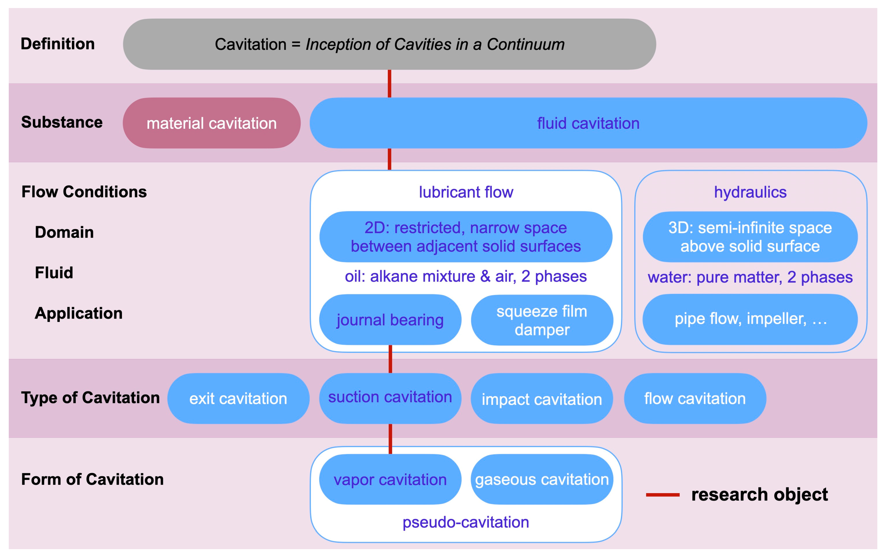
The work on cavitation demands a precise definition of the term itself, the process and its particular conditions. In general, cavitation is defined as an inception of bubbles in a continuum. The second-tier category differentiates the process according to the substance in which the cavity occurs. It is material cavitation, if the cavity is a result of erosion on the surface of, e.g., a bearing liner or a hydraulic component. If the cavity is a gas- or vapor-filled bubble in a fluid, the category is fluid cavitation.
In an effort to define and separate cavitation in lubricant flows from other areas of research, e.g., hydraulics, the authors suggest summarizing characteristic flow conditions in a third tier. The flow domain of lubricant flows is a two-dimensional liquid film restricted by two adjacent walls and bubble diameters are of the same magnitude as the clearance between the shaft and bearing housing, which is a paramount difference from cavitation research in general. Additionally, lubricants always contain a significant amount of dissolved air according to Osterland [
1], which is a further significant contrast to cavitation in water. Typical applications of lubrication are journal bearings and squeeze film dampers.
For journal bearings, which are the research object of the work on hand, the characterization of the cavitation type follows common state-of-the-art definitions established by comprehensive studies of Gläser [
2], Garner et al. [
3], and Engel [
4]. Following the observation of Osterland [
1] that lubricants always contain a significant amount of dissolved air, both forms of cavitation, gaseous and vaporous cavitation, must be considered. According to the findings of Braun and Hendricks [
5] and more recently, Braun and Hannon [
6], the forms of cavitation can be defined as such:
Gaseous cavitation occurs when dissolved gas is released out of the lubricant and gas-filled bubbles are formed.
Vapor cavitation occurs when the liquid lubricant is subject to a local pressure below its vapor pressure and spontaneous evaporation engenders vapor-filled bubbles.
Pseudo-cavitation occurs when gas-filled bubbles change their size without any mass transfer with the surrounding liquid.
In his dissertation, Borbe [
7] investigated fluid cavitation in wastewater and concluded that vapor cavitation is the mechanism that results in material cavitation or erosion. This conclusion is confirmed for lubricant flows; Braun and Hannon [
6] and Leonard et al. [
8] concur that only vapor cavitation may lead to material cavitation and erosion. In an extensive analysis of displacement curves of the crankshaft inside the main bearings of an eight-cylinder diesel engine, Graf and Kollmann [
9] identify sections of the load cycle and thus areas of the bearing liner which are prone to cavitation damage caused by suction cavitation. They surmise that the risk of cavitation correlates with the dynamics of the film thickness. Consequently, the work on hand follows this approach by introducing vapor bubbles solely by an unsteady increase in the thickness of the fluid film. In a recent work [
10], the authors give a detailed overview of cavitation-related works and motivate their research for the particular case of journal bearings inside diesel engines.
Figure 1 displays a nomenclature and summarizes the overview.
2. Method and Materials
2.1. Experiment
The experimental set-up is a further development of the Couette flow apparatus that was presented originally by Reinke et al. [
11], and has recently been modified to study gaseous cavitation [
10]. The authors conclude that the inception of vapor bubbles demands a more dynamic increase of the film thickness.
According to
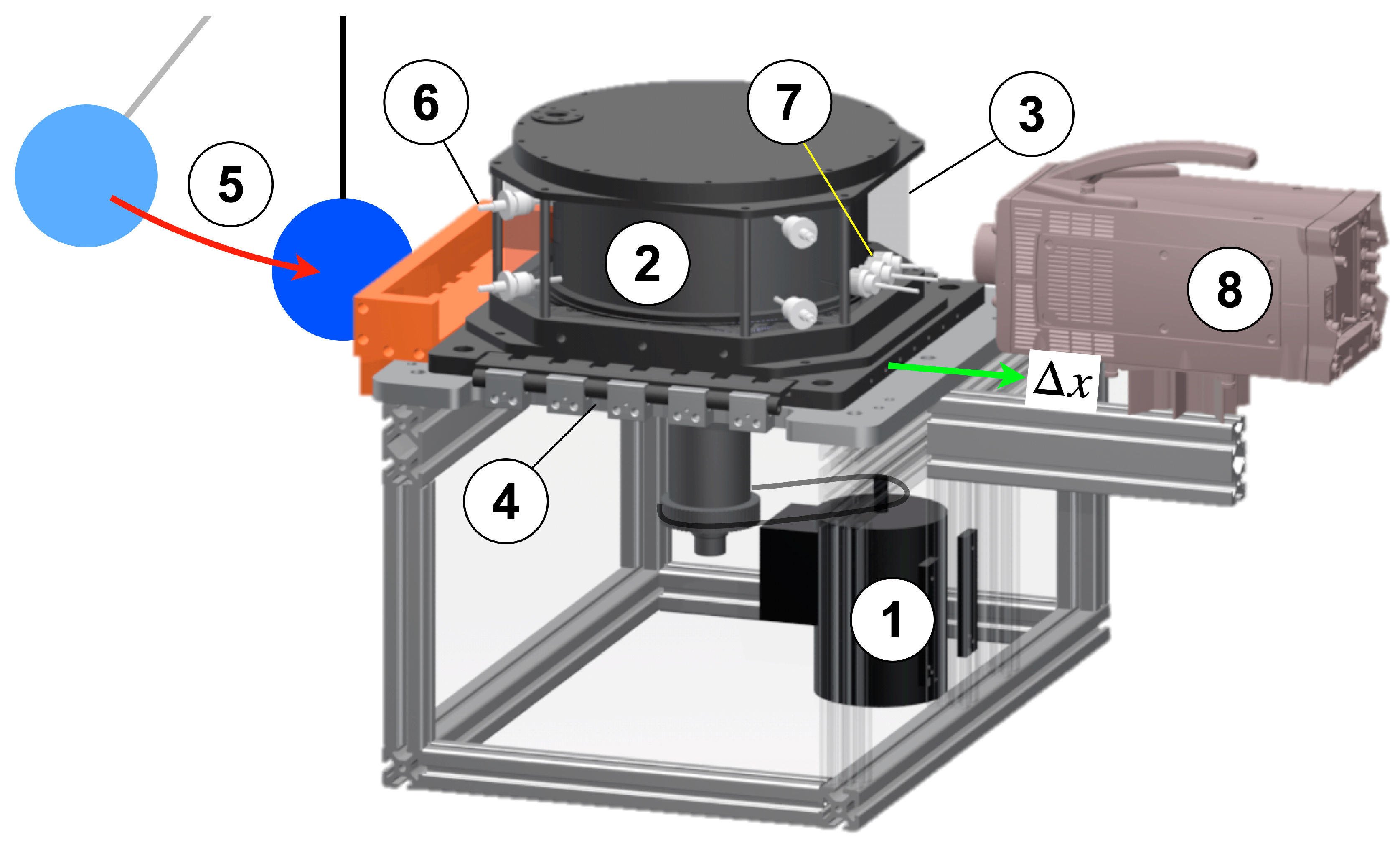
Figure 2, the Journal Bearing Model Experiment incorporates an electric motor (1) which drives a cylinder (2) located inside a housing with a cylindrical cavity (3). The housing is made of polymethyl methacrylate (PMMA), precision machined and polished, providing the necessary optical quality which, together with its octagonal outer shape, enables an unrestricted radial optical access to the cavity. A plain side of the octagon is positioned orthogonally to the optical axis of the image area.
The cylinder (2) rotates with a given rotational speed
and is positioned eccentrically in relation to the axis of the cavity. The initial position is
. Due to the rotation of the cylinder, which is powered by the motor (1), a journal bearing type flow develops inside the fluid film. The cavity encloses the cylinder completely; thus, the clearance at the top and bottom of the cylinder gives space for a cross-flow from the pressure maximum towards the pressure minimum. The pressure difference is a result of the circumferential flow. In addition to the original design [
11], the housing (3) is mounted on a linear traversing guide (4) which assures precise positioning in relation to the cylinder (2) and control of the minimum fluid film thickness between (2) and (3). Previously [
10], a pneumatic actuator and a rocker mechanism propelled the housing, resulting in a dynamic variation of the film thickness that was fast enough to produce gaseous cavitation. However, the formation of vapor cavitation demands a jerk resulting in a more dynamic displacement. Consequently, the apparatus is fitted with a pendulum (5) which swings towards the base of the housing. Upon impact, the kinetic energy of the pendulum’s mass is transferred to the housing resulting in a jerk which initiates the housing’s displacement. Hence, the thickness of the lubricant film between (2) and (3) increases abruptly with the necessary displacement velocity.
Additional measurement devices are pressure taps (6) at the bottom and the top of the housing (3) and three displacement sensors (7) detecting the distance between the cavity (3) and rotating cylinder (2). The algorithm for the computation of
based on these distance data is presented in [
11]. The digital high-speed camera (8) completes the set-up.
2.2. Camera
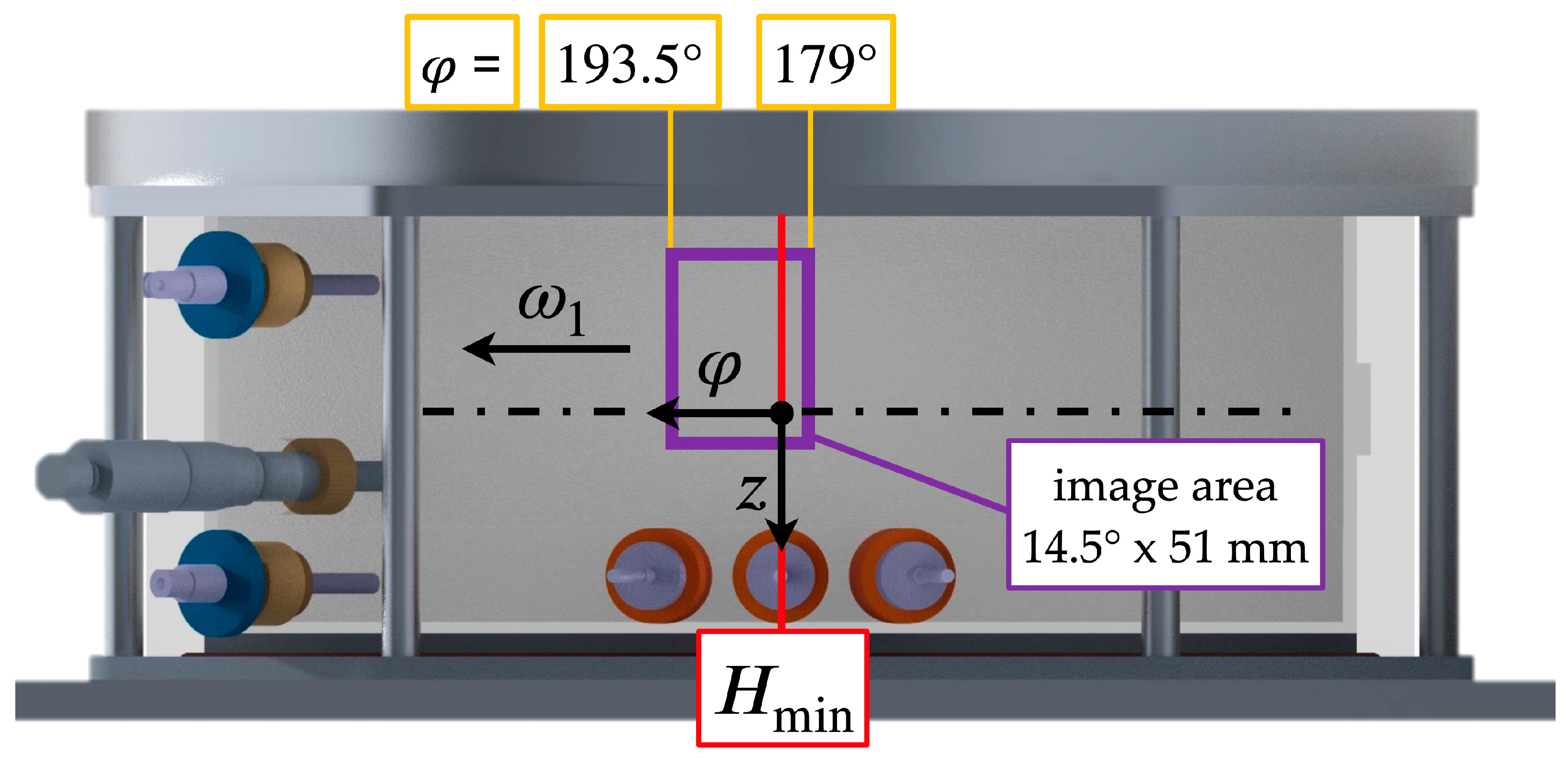
Figure 3 shows the camera’s view and the image area
A, across which the image processing is performed. The image area is downstream of the minimum film thickness
inside the divergent section of the fluid film. The Sommerfeld angle
indicates the lateral position. The optical set-up follows the previous work [
10]. A high-speed camera (
IX-Cameras i-Speed 720) is used to capture bubble formation and transport inside the liquid film. The maximum data capacity of the camera is 20 Gpx/s. Hence, the resolution and frame rate have to be balanced. The experiment is recorded with a resolution of 1512 × 1098 pixels at 10,000 frames per second (fps). Based on a physical resolution of 25 px, which defines the minimum detection limit for the smallest bubble, the exposure time is set at 100 μs. Additionally, major components, including a fast lens with macro capacity (
Walimex T3.1 100 mm ED) and artificial lighting (two spotlights
Hedler ProfiLux LED 1000 with a combined luminous flux of 50,000 lm), complete the set-up. Due to the experiment’s physical dimensions, the lens must support close focus with a respective magnification ratio of 1:1.
2.3. Cavitation Fluid and Dissolved Gas
The cavitation fluid, which is specifically designed for the experimental tests, is a mixture of paraffin oil (CAS-8042-47-5) and pentane (isopentane, C
5H
12), which is transparent, providing excellent optical access while its physical properties fulfill similarity demands. The pentane fraction reduces the boiling point of the fluid and makes it more susceptible to cavitation. A similar cavitation fluid was successfully used to study a new type of Taylor vortex flow [
12].
Due to the fact that gaseous cavitation reduces the effect of vapor cavitation, the air content of the actual fluid in use is monitored by means of a fibre-optic oxygen sensor (
pyroscience OXSOLV-PTS) detecting the infrared absorption spectrum of oxygen. The detected oxygen reading is compared with a reference reading of pure paraffin at standard pressure and 23 °C where the air content
is documented. The ratio of the oxygen reading
of the fluid in use vs. the reference reading
of pure paraffin leads to the air content in question, according to Equation (1). Peters et al. [
13] have applied this method successfully in their study pertaining to air degassing from oil.
2.4. Broader Perspective and Physical Parameters
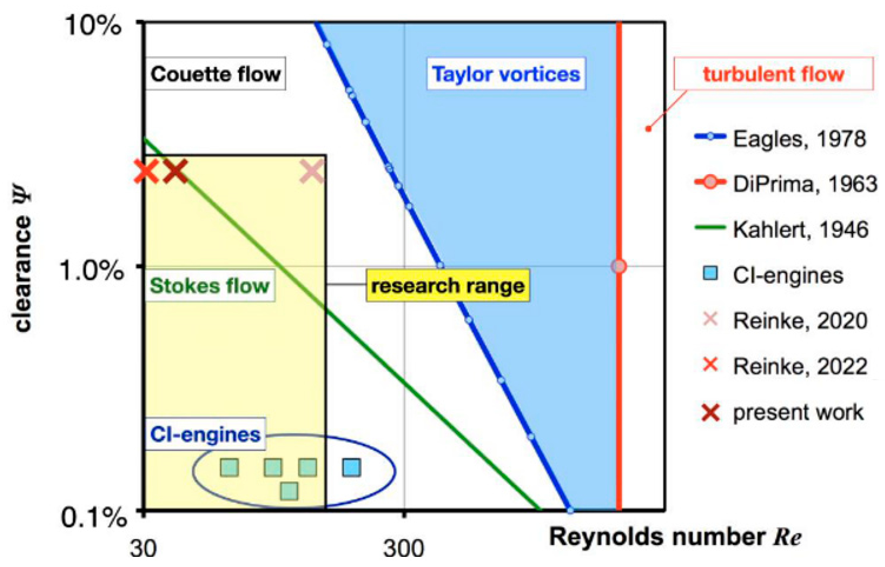
The diagram displayed in
Figure 4 puts this work into a broader perspective in relation to previous work [
10,
11] and other studies pertaining to the Taylor–Couette flow at low clearance ratios. The diagram shows the Reynolds number and the clearance ratio that are addressed in this work. Compared to recent work [
10,
11] with operating points located at the corners of the targeted research range that extends towards the operational range of journal bearings in CI-engines, the current experimental campaign is carried out exactly below the limit proposed by Kahlert [
14] but still inside the domain of the Stokes flow. The limit for the Stokes flow region is defined by Equation (2)
Moreover, the borders to the Taylor vortex flow according to Eagles et al. [
15] and to the fully turbulent flow according to DiPrima [
16], are displayed as well. It can be surmised that turbulence is of no concern, because at the given clearance the Reynolds number is more than one order of magnitude below the critical value. All substantial operational parameters are listed in
Table 1 for further reference.
3. Results
3.1. High Speed Photography—Raw Material
The paramount contribution of this work is in forcing the inception of vapor bubbles in a lubricant type flow that are solely engendered by an unsteady increase in the film thickness. The increase in the film thickness depends on the radial displacement of the cylindrical cavity (3) in relation to the rotating cylinder (2). The sequence of
Figure 5,
Figure 6,
Figure 7,
Figure 8,
Figure 9,
Figure 10 and
Figure 11 shows digital photography collected at a speed of 10,000 fps across the circumferential section of the fluid film downstream from
to a Sommerfeld angle of 193° across a width of 51 mm. The images capture the life cycle of a selected vapor bubble during its seven phases: inception (1), growth (2), maximum bubble size (3), contraction (4), unsteady collapse (5), re-bounce (6) and remains of collapsed bubble (7). By means of image processing, the cycle lifetime of a vapor bubble is measured to last from the inception to the end of the first collapse and the average is calculated to be
Firstly, compared to the cycle lifetime of a gas bubble, which was found to be 8.3 ms [
10] from inception to reaching the final stage of a residual bubble, the vapor bubble’s life is significantly shorter. Secondly, after the collapse and the rebounding, a vapor bubble leaves no remains while a gas bubble is compressed and the residual gas mass remains inside the fluid film and accumulates during the entire duration of the experiment.
The following
Figure 5,
Figure 6,
Figure 7,
Figure 8,
Figure 9,
Figure 10 and
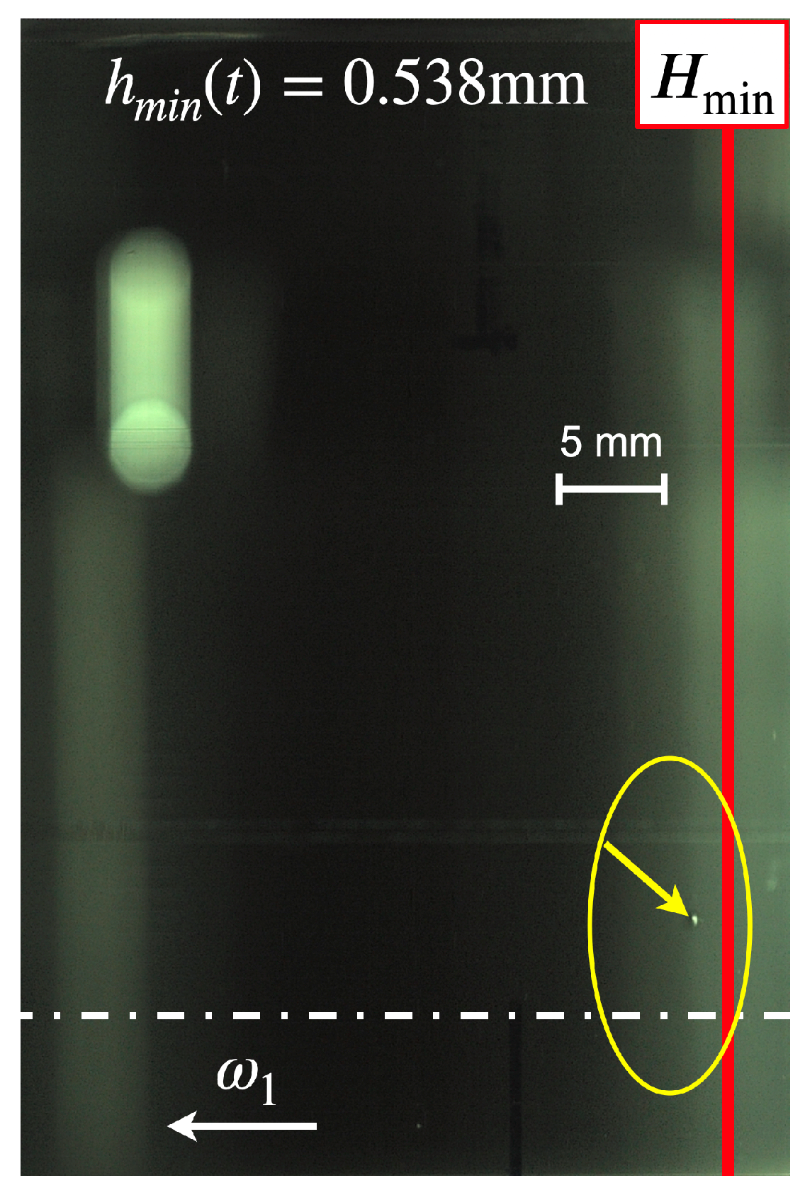
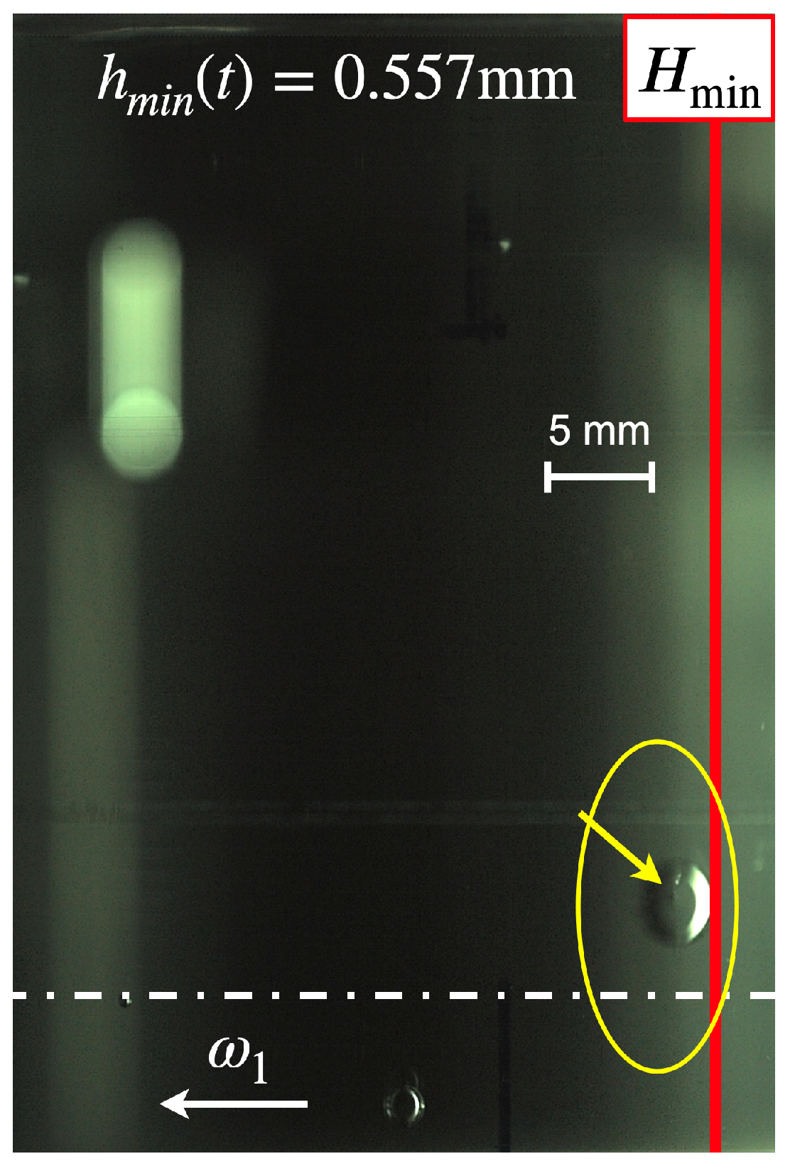
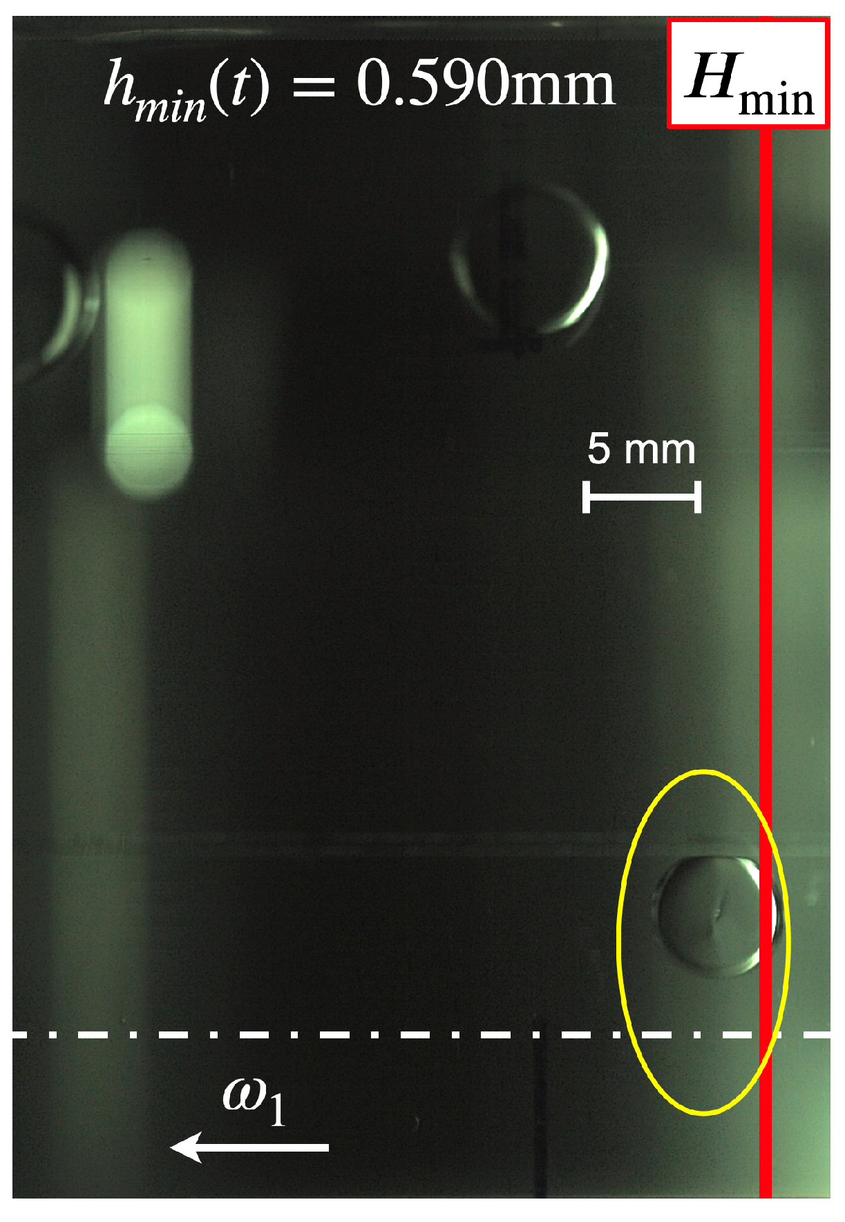
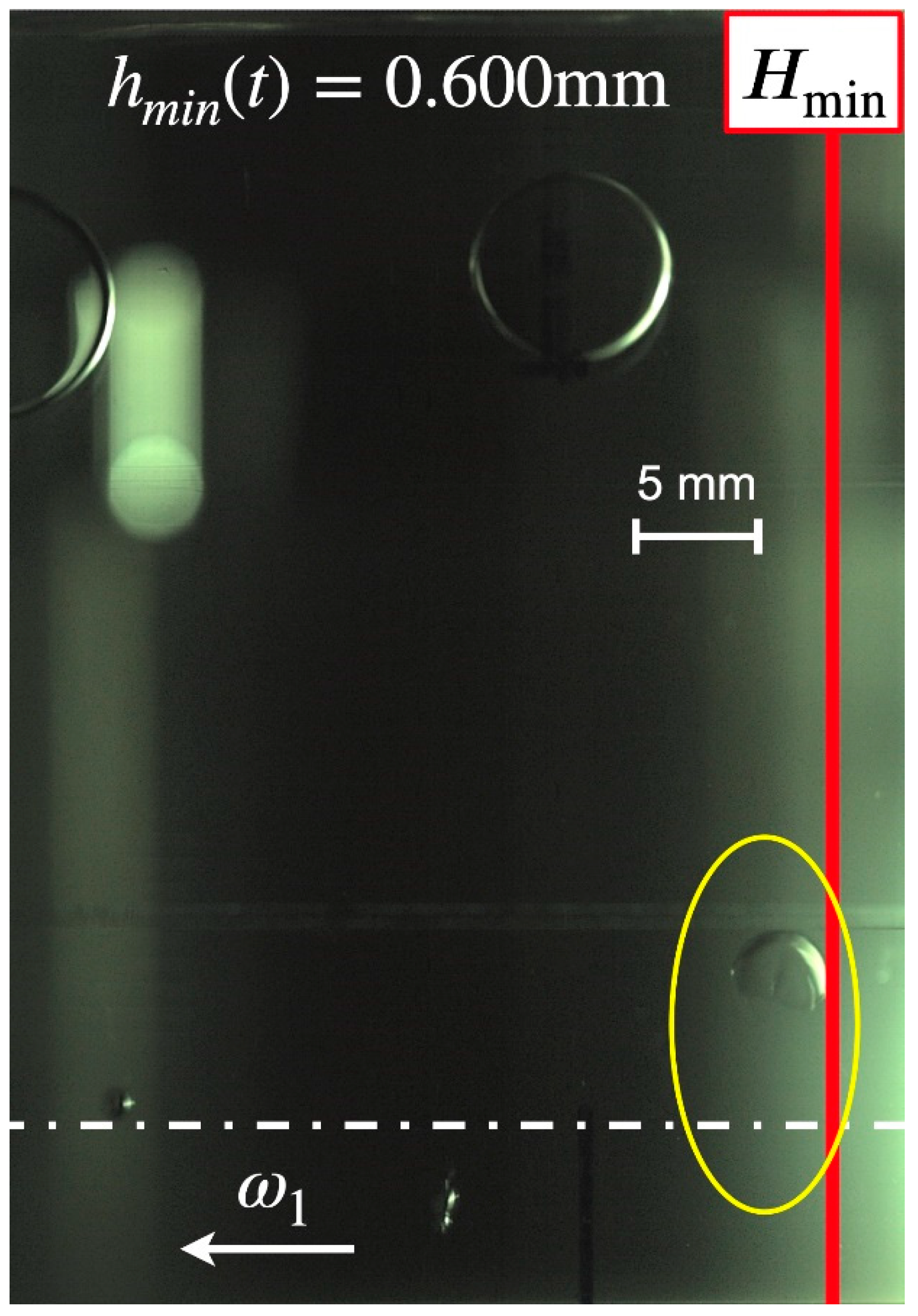
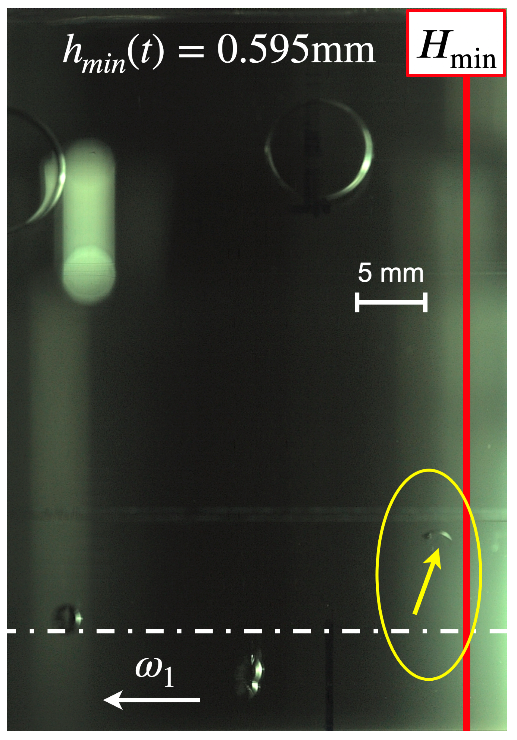
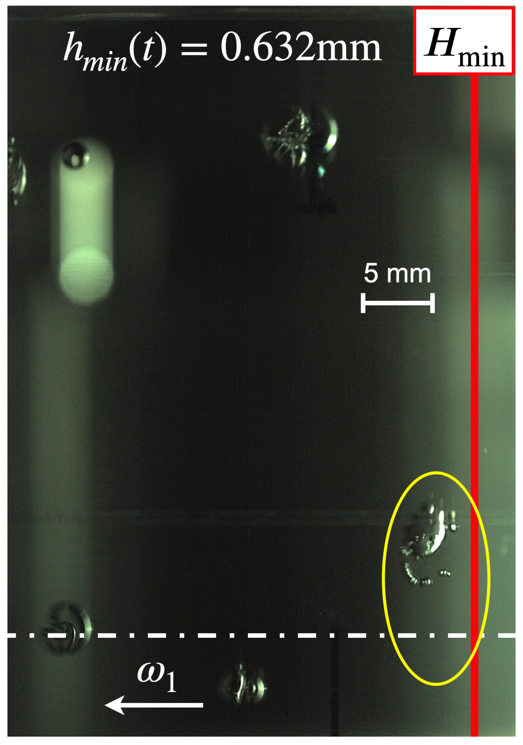
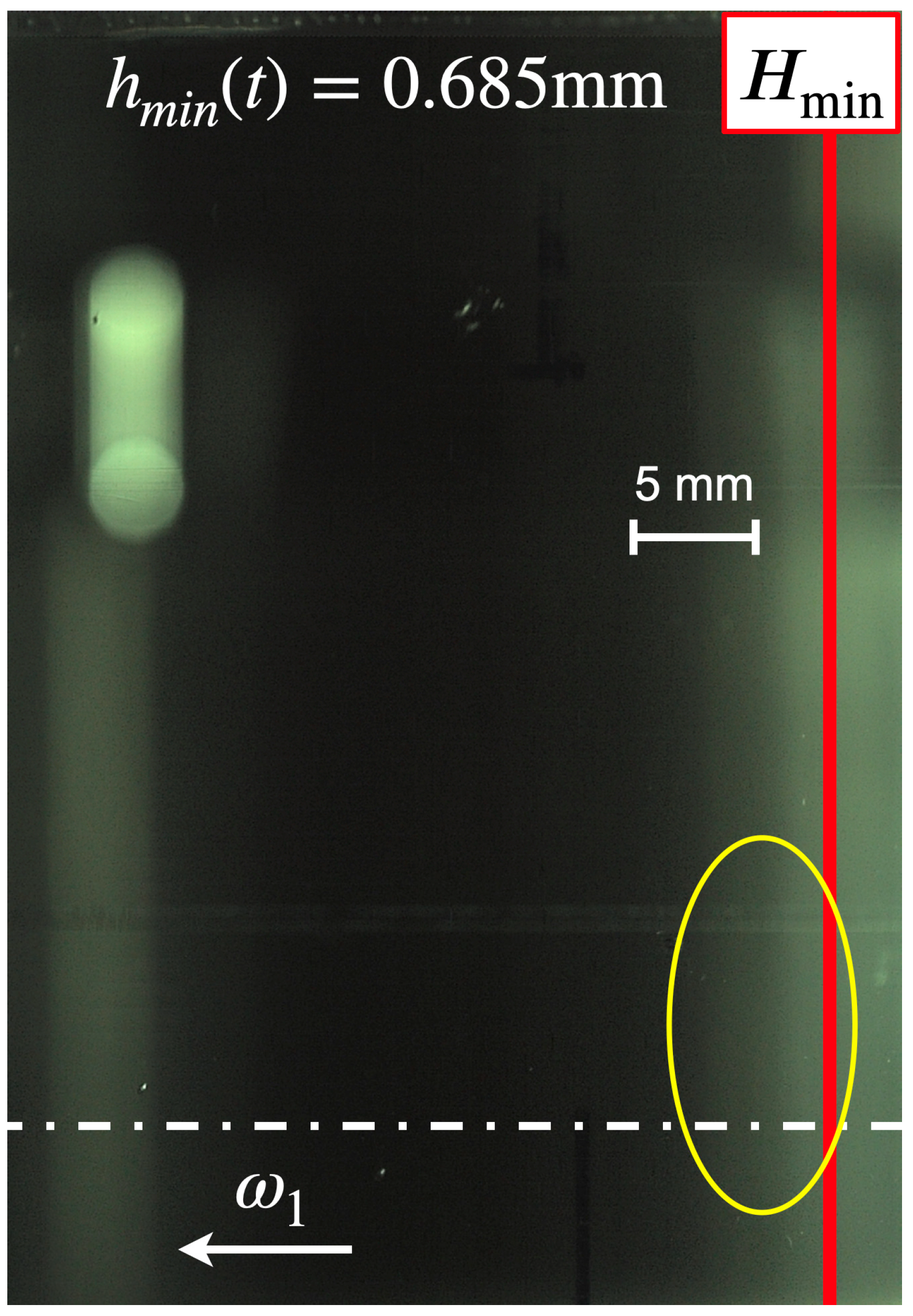
Figure 11 display a digital image of a selected vapor bubble during its life cycle. A reference indicates a scale of 5 mm and the location of the minimum film thickness is marked by the red line while its actual value is shown at the top of each image at the Sommerfeld angle
= 180°. The rotational direction of the inner cylinder is to the left and the cylinder’s equator is indicated by the broken white line according to the convention given in
Figure 3.
Figure 6 displays the growing vapor bubble 0.2 ms after inception. The yellow arrow indicates the bubble contour where it touches the wall of the cavity.
Figure 9 displays the imploding vapor bubble 0.9 ms after inception. The yellow arrow indicates the bubble contour that is shaped like a crescent. The duration of the implosion is less than an increment of the frame rate of 0.1 ms.
Figure 11 displays the area where the vapor bubble imploded. The yellow ellipse encircles the area 3.2 ms after inception. No visible remains or rest gas can be observed, which proves that a complete condensation of the vapor occurred and the re-liquified pentane dissolved entirely into the paraffin.
3.2. High Speed Photography—Evaluation by Digital Imaging
In a previous work [
10], the authors studied a lubricant flow with gaseous cavitation that was incepted by an unsteady increase in the film thickness. That unsteady process was actuated by means of a pneumatic cylinder and a rocker mechanism which displaced the housing in relation to the rotating cylinder. Based on those results, the authors surmised that the rapidity in the unsteady increase of the fluid film thickness must be greater in order to force the fluid to produce vapor cavitation. Hence, the work on hand utilizes a new mechanism where a pendulum forces a jerk to start the displacement of the housing and to increase the fluid film thickness more rapidly.
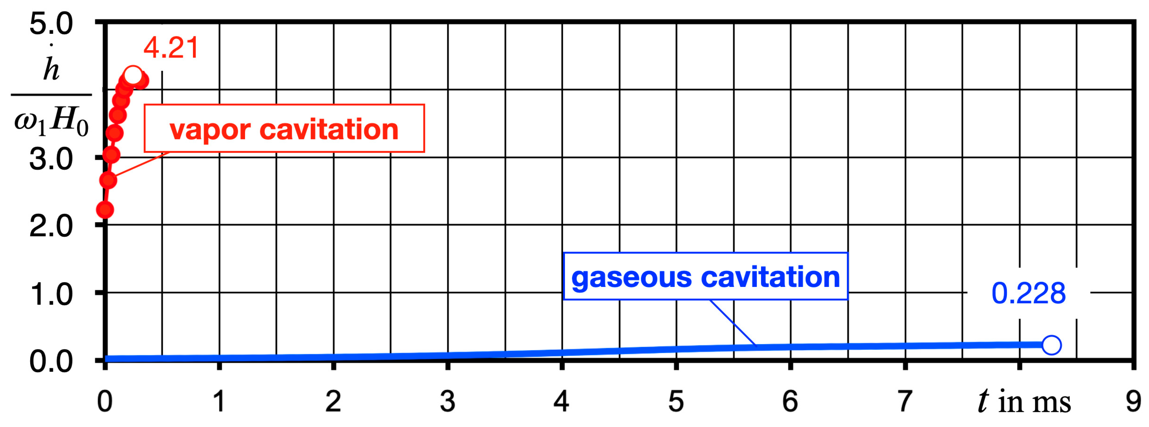
Figure 12 displays typical curves of the displacement velocity based on the normalized momentary minimal fluid film thickness versus time. The time scale is synchronized at the moment when the bubbles inception starts (
t = 0). The new mechanism reaches the maximum displacement velocity already within 0.2 ms after the pendulum releases its impact force onto the linear transverse (4). Thus, not only is the acceleration rate of the film thickness higher, but the maximum displacement velocity is also higher than both kinematic properties which were achieved when gaseous cavitation was produced by means of the pneumatic cylinder.
The successful implementation of the new mechanism capable of forcing the necessary magnitude of the displacement velocity and, thus, increasing the fluid film’s thickness yields vapor cavitation that is documented by the bubble growth rate and the fact that after collapsing and re-bouncing a vapor bubble leaves no remaining rest.
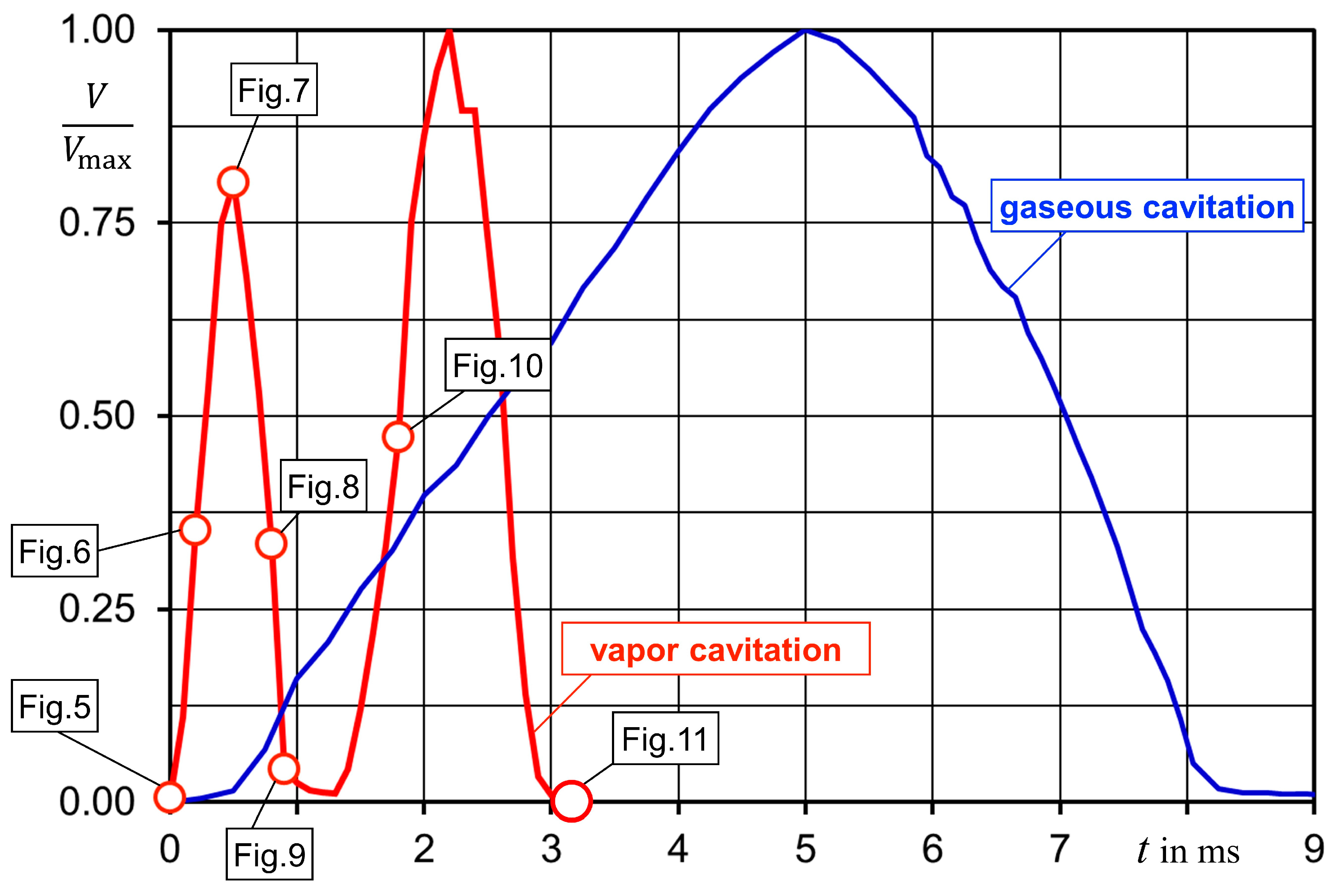
Figure 13 summarizes the results of image processing comparing the development of vapor bubbles with air bubbles that were analyzed earlier [
10]. Compared with the comprehensive study of Podbevšek et al. [
17] pertaining to other methods, e.g., pulsed laser, electrical discharge, tube arrest, applied to produce vapor bubbles, the work on hand proves the applicability of this novel approach to study vapor cavitation in fluid films similar to lubricant flows.
The seven phases of a vapor bubble’s life cycle are indicated in
Figure 13, making reference to the digital images (
Figure 5,
Figure 6,
Figure 7,
Figure 8,
Figure 9,
Figure 10 and
Figure 11). After inception (phase 1), the bubble grows (phase 2), reaching its maximum size (phase 3) within 0.5 ms. After a short stagnation, the bubble begins to contract (phase 4), followed by its collapse (phase 5) that starts at approximately 0.9 ms after inception. The selected bubble re-bounces (phase 6) once and vanishes completely (phase 7), without leaving any amount of rest gas. It can be noted that the life cycle of a vapor bubble is significantly shorter compared to an air bubble with a cycle time of 8.3 ms. Moreover, the experimental data show that the gas mass of the air bubble also remains constant while the bubbles decrease in size. This result confirms the observations of Zhou et al. [
18], who found that gas release is a fast process, but that absorption evolves 10,000 times more slowly.
4. Discussion
This work presents experimental results of vapor cavitation based on digital high-speed photography of a lubricant-type flow in the eccentric gap between a rotating cylinder and a cylindrical cavity. The vapor cavitation’s type is similar to suction cavitation in a dynamically loaded journal bearing. An unsteady increase in the fluid film thickness causes this cavitation type. In contrast to other work, where pulsed laser or electric discharge is applied to induce cavitation, the presented experimental approach is solely based on the displacement of the housing versus the rotating shaft, resulting in the unsteady increase in the thickness of the fluid film. Hence, the entire process is similar to conditions inside the lubricant film in dynamically loaded journal bearings.
Departing from earlier results related to gaseous cavitation, the authors surmised that the production of vapor cavitation demands a faster increase in the fluid film thickness. Therefore, a modified mechanism is applied which utilizes the kinetic energy of a pendulum to create a jerk with an impact force strong enough to force the necessary unsteady displacement velocity of housing. Displacement data show that this method yields a radial displacement velocity of the housing which is more than a magnitude higher than the one generated by means of a pneumatic cylinder.
With a time resolution of 10,000 fps, the high-speed imaging system provides digital photography of the entire development of vapor bubbles from inception to collapse. Compared to gaseous bubbles which grow due to a mass transfer based on gas release, and in combination with pseudo-cavitation, vapor bubbles grow only due to the mass transfer as a result of the change of state of the liquid or a low-boiling component of the liquid mixture. The authors assume that the rapidity of vapor cavitation inhibits pseudo-cavitation.
The following open questions remain. What effect does the saturation level of the air in the fluid have on the result? Earlier experiments show that, at very low air content, gaseous cavitation ceases altogether. What is the correlation between the eccentricity and rapidity of the increase in the fluid film thickness in relation to the onset of vapor cavitation? This correlation could lead to the definition of a limit of vapor cavitation in dynamically loaded journal bearings, which in turn is important for bearing design because only vapor cavitation can result in material cavitation and erosion of the bearing liner.
Author Contributions
Conceptualization and methodology, P.R.; software, M.S.; validation, T.B., J.A. and P.R.; formal analysis, P.R.; camera and optical resources, C.A., J.A. and L.H.; experiments and data curation, T.B. and C.A.; writing—original draft preparation, P.R.; writing—review and editing, P.R., J.A., T.B. and M.S.; visualization, M.S.; supervision and project administration, P.R.; funding acquisition, P.R. All authors have read and agreed to the published version of the manuscript.
Funding
This research is funded by the Deutsche Forschungsgemeinschaft (DFG, German Research Foundation)—Proj. No. 462581008.
Data Availability Statement
The data presented in this study are available on request from the corresponding author.
Acknowledgments
The authors wish to acknowledge the constant support of Wolfgang Viöl, Vice President of Research and Transfer at the HAWK Goettingen. The authors’ special thanks must be reserved for Konstantin Goetz who put his creative skills to work and visualized vapor cavitation in a very self-explanatory graphic abstract.
Conflicts of Interest
The authors declare that there is no conflict of interest.
Nomenclature
| image area |
| air content of fluid in use |
| air content of paraffin at 23 °C |
| cylinder height, fluid film width |
| diameter of bubble |
| initial eccentricity |
| clearance between cylinder (2) and cavity (3) |
| minimal fluid film thickness |
| displacement velocity |
| momentary minimal fluid film thickness |
| local pressure |
| saturation pressure of a gas dissolved in the liquid |
| vapor pressure |
| unique gas constant of pentane |
| operating temperature |
| radius of inner cylinder |
| radius of cavity |
| Reynolds number |
| time |
| bubble volume |
| maximum bubble volume |
| oxygen reading of fluid in use |
| oxygen reading of paraffin at 23 °C |
| axial coordinate |
| displacement |
| Greek Symbols |
| relative initial eccentricity |
| kinematic viscosity |
| dynamic viscosity |
| fluid density |
| Sommerfeld angle |
| rotational angle |
| normalized clearance |
| rotational speed of inner cylinder |
References
- Osterland, S.; Mueller, L.; Weber, J. Influence of air dissolved in hydraulic oil on cavitation erosion. Int. J. Fluid Power 2021, 22, 373–392. [Google Scholar] [CrossRef]
- Gläser, H. Schäden an Gleit- und Wälzlagerungen, 1st ed.; Verlag Technik: Berlin, Germany, 1990; ISBN 97833410-0798-3. [Google Scholar]
- Garner, D.R.; James, R.D.; Warriner, J.F. Cavitation Erosion Damage in Engine Bearings: Theory and Practice. J. Eng. Power 1980, 102, 847–857. [Google Scholar] [CrossRef]
- Engel, U. Schäden an Gleitlagern in Kolbenmaschinen. In Schäden an Geschmierten Maschinenelementen: Gleitlager, Wälzlager, Zahnräder, 2nd ed.; Bartz, W., Ed.; Expert-Verlag: Renningen, Germany, 1992; p. 36436. ISBN 978-3-8169-0255-3. [Google Scholar]
- Braun, M.J.; Hendricks, R.C. An experimental investigation of the vaporous/gaseous cavity characteristics of an eccentric journal bearing. ASLE Trans. 1984, 27, 1–14. [Google Scholar] [CrossRef]
- Braun, M.J.; Hannon, W.M. Cavitation formation and modelling for fluid film bearings: A review. Proc. Inst. Mech. Eng. Part J J. Eng. Tribol. 2010, 224, 839–863. [Google Scholar] [CrossRef]
- Borbe, P.C. Beitrag zur Werkstoffzerstörung durch Strömungskavitation in Kalten und Warmen Brauchwässern. Ph.D. Thesis, Universität Hannover, Hannover, Germany, 1968. [Google Scholar]
- Leonard, B.; Sadeghi, F.; Cipra, R. Gaseous cavitation and wear in lubricated fretting contacts. Tribol. Trans. 2008, 51, 351–360. [Google Scholar] [CrossRef]
- Graf, G.; Kollmann, K. Untersuchungen der Hauptlager Eines 8-Zylinder-4-Takt-Schiffsdieselmotors. In FVV-Forschungsbericht; Nr. 2-211/10; FVV: Frankfurt/Main, Germany, 1964; pp. 1–69. [Google Scholar]
- Reinke, P.; Ahlrichs, J.; Beckmann, T.; Schmidt, M. High-Speed Digital Photography of Gaseous Cavitation in a Narrow Gap Flow. Fluids 2022, 7, 159. [Google Scholar] [CrossRef]
- Reinke, P.; Ahlrichs, J.; Beckmann, T.; Schmidt, M. Bubble dynamics in a narrow gap flow under the influence of pressure gradient and shear flow. Fluids 2020, 5, 208. [Google Scholar] [CrossRef]
- Reinke, P.; Schmidt, M.; Beckmann, T. The cavitating Taylor-Couette flow. Phys. Fluids 2018, 30, 104101. [Google Scholar] [CrossRef]
- Peters, F.; Nuellig, M.; Hoehne, A. Air degassing from oil. In Lasermethoden in der Strömungsmesstechnik. In Proceedings of the 23rd conference of the German Association for Laser Anemometry, Dresden, Germany, 8–10 September 2015; ISBN 978-3-9816764-1-9. [Google Scholar]
- Kahlert, W. Untersuchungen über den Einfluß der Trägheitskräfte bei der Hydrodynamischen Schmiermitteltheorie. Ph.D. Thesis, Technical University Braunschweig, Braunschweig, Germany, 1946. [Google Scholar]
- Eagles, P.; Stuart, J.T.; DiPrima, R.C. The effects of eccentricity on torque and load in Taylor-vortex flow. J. Fluid Mech. 1978, 87, 209–231. [Google Scholar] [CrossRef]
- DiPrima, R.C. A Note on the Stability of Flow in Loaded Journal Bearings. ASLE Trans. 1963, 6, 249–253. [Google Scholar] [CrossRef]
- Podbevšek, D.; Lokar, Ž.; Podobnikar, J.; Petkovšek, R.; Dular, M. Experimental evaluation of methodologies for single transient cavitation bubble generation in liquids. Exp. Fluids 2021, 62, 167. [Google Scholar] [CrossRef]
- Zhou, J.; Vacca, A.; Manhartsgruber, B.A. Novel Approach for the Prediction of Dynamic Features of Air Release and Absorption in Hydraulic Oils. J. Fluids Eng. 2013, 135, 1–8. [Google Scholar] [CrossRef]
Figure 1.
Nomenclature and overview of cavitation, comprehensive comparison between lubricant flow and hydraulics.
Figure 1.
Nomenclature and overview of cavitation, comprehensive comparison between lubricant flow and hydraulics.
Figure 2.
Journal Bearing Model Experiment, consisting of motor (1), cylinder (2) rotating inside the transparent cavity (3), linear traversing guide (4), pendulum (5), pressure taps (6), displacement sensors (7) and digital high-speed camera (8). ∆x denotes the radial displacement of (3) in relation to (2).
Figure 3.
Optical access into the fluid film; viewing area located downstream of minimum film thickness.
Figure 3.
Optical access into the fluid film; viewing area located downstream of minimum film thickness.
Figure 4.
Stability diagram of the Taylor–Couette flow developed from Reinke et al. [
12].
Figure 4.
Stability diagram of the Taylor–Couette flow developed from Reinke et al. [
12].
Figure 5.
Inception of vapor bubble, phase 1, at t = 0.0 ms, cavitation fluid: 96.4% paraffin and 3.6% pentane. The arrow indicates the vapor bubble.
Figure 5.
Inception of vapor bubble, phase 1, at t = 0.0 ms, cavitation fluid: 96.4% paraffin and 3.6% pentane. The arrow indicates the vapor bubble.
Figure 6.
Growing vapor bubble, phase 2, at t = 0.2 ms after its inception, cavitation fluid: 96.4% paraffin and 3.6% pentane.
Figure 6.
Growing vapor bubble, phase 2, at t = 0.2 ms after its inception, cavitation fluid: 96.4% paraffin and 3.6% pentane.
Figure 7.
Maximum size of vapor bubble, phase 3, at t = 0.5 ms after its inception, cavitation fluid: 96.4% paraffin and 3.6% pentane.
Figure 7.
Maximum size of vapor bubble, phase 3, at t = 0.5 ms after its inception, cavitation fluid: 96.4% paraffin and 3.6% pentane.
Figure 8.
Contracting vapor bubble, phase 4, at t = 0.8 ms after its inception, cavitation fluid: 96.4% paraffin and 3.6% pentane.
Figure 8.
Contracting vapor bubble, phase 4, at t = 0.8 ms after its inception, cavitation fluid: 96.4% paraffin and 3.6% pentane.
Figure 9.
Imploding vapor bubble, phase 5, at t = 0.9 ms after its inception, cavitation fluid: 96.4% paraffin and 3.6% pentane. The arrow indicates the vapor bubble’s deformation.
Figure 9.
Imploding vapor bubble, phase 5, at t = 0.9 ms after its inception, cavitation fluid: 96.4% paraffin and 3.6% pentane. The arrow indicates the vapor bubble’s deformation.
Figure 10.
Rebounding vapor bubble, phase 6, at t = 1.8 ms after its inception, cavitation fluid: 96.4% paraffin and 3.6% pentane.
Figure 10.
Rebounding vapor bubble, phase 6, at t = 1.8 ms after its inception, cavitation fluid: 96.4% paraffin and 3.6% pentane.
Figure 11.
Remains of collapsed vapor bubble, phase 7, at t = 3.2 ms after its inception, cavitation fluid: 96.4% paraffin and 3.6% pentane.
Figure 11.
Remains of collapsed vapor bubble, phase 7, at t = 3.2 ms after its inception, cavitation fluid: 96.4% paraffin and 3.6% pentane.
Figure 12.
Development of the displacement velocity after initiation of transient radial displacement, vapor cavitation in cavitating fluid (paraffin 96.4%, pentane 3.6%) and gaseous cavitation in paraffin saturated with air [
10], respectively.
Figure 12.
Development of the displacement velocity after initiation of transient radial displacement, vapor cavitation in cavitating fluid (paraffin 96.4%, pentane 3.6%) and gaseous cavitation in paraffin saturated with air [
10], respectively.
Figure 13.
Development of the bubble volume, vapor cavitation in cavitating fluid (paraffin 96.4%, pentane 3.6%) and gaseous cavitation in paraffin saturated with air [
10].
Figure 13.
Development of the bubble volume, vapor cavitation in cavitating fluid (paraffin 96.4%, pentane 3.6%) and gaseous cavitation in paraffin saturated with air [
10].
Table 1.
Physical parameters of the experiment.
Table 1.
Physical parameters of the experiment.
| Symbol | Value | Definition | Description |
|---|
| 111.0 mm | | cylinder height |
| 3.082 mm | | initial eccentricity |
| 3.620 mm | | clearance between cylinder and cavity |
| 0.538 mm | | absolute minimal fluid film thickness |
| 146.44 mm | | radius of inner cylinder |
| 150.06 mm | | radius of cavity |
| 293 K | | operating temperature |
| 85.1% | | relative initial eccentricity |
| 2.47% | | normalized clearance |
| 8.14 1/s | | rotational speed of cylinder (2) |
| 38.2 | | Reynolds number |
| Properties of paraffin at 23 °C |
| 872 kg/m3 | | paraffin density |
| 0.1094 | | air content |
| Properties of the cavitation fluid at T0 |
| 868 kg/m3 | | fluid density |
| 98.2 mPa s | | dynamic viscosity |
| 113 mm2/s | | kinematic viscosity |
| 3.6% | | pentane fraction |
| 2766 Pa | | vapor pressure |
| 115.5 J/kg K | | unique gas constant of pentane |
| Disclaimer/Publisher’s Note: The statements, opinions and data contained in all publications are solely those of the individual author(s) and contributor(s) and not of MDPI and/or the editor(s). MDPI and/or the editor(s) disclaim responsibility for any injury to people or property resulting from any ideas, methods, instructions or products referred to in the content. |
© 2023 by the authors. Licensee MDPI, Basel, Switzerland. This article is an open access article distributed under the terms and conditions of the Creative Commons Attribution (CC BY) license (https://creativecommons.org/licenses/by/4.0/).


