1. Introduction
Fluid motion between eccentric cylinders can be found in various engineering applications. The stability of a viscous fluid between two rotating cylinders was first studied by Taylor in 1923 [
1] and since then has been considered in different configurations [
2,
3,
4].
Cavitation is vapor bubble formation that occurs in a fluid when the absolute static pressure reaches or drops below the vapor pressure of the liquid at a given temperature [
5]. The most common cavitation types, observed in industry and also used in different applications of chemical and mechanical engineering, are hydrodynamic and acoustic. Acoustic cavitation is the formation and collapse of vapor bubbles in a fluid irradiated by intense ultrasound. The speed of the bubble collapse sometimes reaches the sound velocity in the liquid [
6] and can produce sonoluminescence, which is the light emission phenomenon from cavitation bubbles in a liquid irradiated by strong ultrasound [
7]. Hydrodynamic cavitation is a process of cavitation bubble generation and implosion, which occurs in the fluid flow as a result of a decrease and subsequent increase in local pressure. Usually, this process is observed at high Reynold numbers, for example, in cavitating jets [
8], which are used in many industrial applications [
9] or behind impeller blades in a centrifugal pump [
10].
Cavitation in a creeping flow of a viscous sheared fluid was observed in [
11] in a Couette viscometer with a thin liquid gap between the static drum and rotating inner cylinder. It was shown that cavitation bubbles developed from preexisting wall-stabilized nuclei. Cavitation can be observed in a journal-bearing arrangement [
12] and in similar geometries at low Reynolds numbers (Re < 1), such as an inner sphere or cylinder free-to-move in creeping regime adjacent to either an inclined static plane wall coated with a thin layer of a viscous fluid or to a rotary outer horizontal cylinder [
13,
14,
15,
16].
In [
17], the laminar flow between two eccentric cylinders was studied numerically for Reynolds numbers between 35–60. With a rotating inner cylinder, it was shown that pressure increased in the converging region of the flow and decreased in the diverging region. It was shown that the pressure gradient caused flow separation, which decreased in the axial direction. In [
18], the flow between eccentric rotating cylinders with a low Reynolds number (Re = 20) when either the outer or inner cylinder is stationary was studied both for the creeping flow approximation and for the case where inertial effects were not negligible. When the centers of the two cylinders were far enough, a two-dimensional recirculation zone appeared in the region where the gap spacing was greatest. On increasing the eccentricity, the recirculation zone became bigger, and the separation and reattachment points moved towards the region of the narrowest gap. In [
19], three approximate solutions of the Navier–Stokes equations were obtained numerically for the two-dimensional flow between two eccentric rotating cylinders (Re = 130) to study a separation phenomenon, which occurred when the eccentricity reached a specific value, and for the prediction of the separation and reattachment points of an eddy created near the outer cylinder. The inner cylinder in this study had a constant angular velocity, and the outer one was stationary. The study [
20] focused on the numerical simulation of buoyancy natural heat transfer by including a new source term in the SST k − ω turbulence mode. Four rotation scenarios were considered: inner counterclockwise rotation, outer counterclockwise rotation, inner–outer clockwise rotation, and inner clockwise–outer counterclockwise rotation. It was shown that the rotational direction affected the mixing temperature by generating a large vortex in the cavity, which increased the temperature mixing performance.
In [
21], cavitation inception was studied experimentally in a creeping flow between eccentric cylinders, the inner one being static and the outer rotating at a constant angular velocity. Cavitation was observed as a set of discrete bubbles on the surface of the inner cylinder along the generatrix of a cylinder at some angular distance from the minimal gap. The discrete nature of the bubbles was explained by the presence of pressure modulation along the generatrix and the presence of charge on the boundary of phase separation (liquid–vapor).
The appearance of cavitation in these systems can significantly misrepresent the conditions of lubrication and heat transfer. The main goal of this paper is a fundamental experimental study of gaseous cavitation in the region of the minimal gap between two eccentric cylinders.
2. Experimental Procedures and Discussion
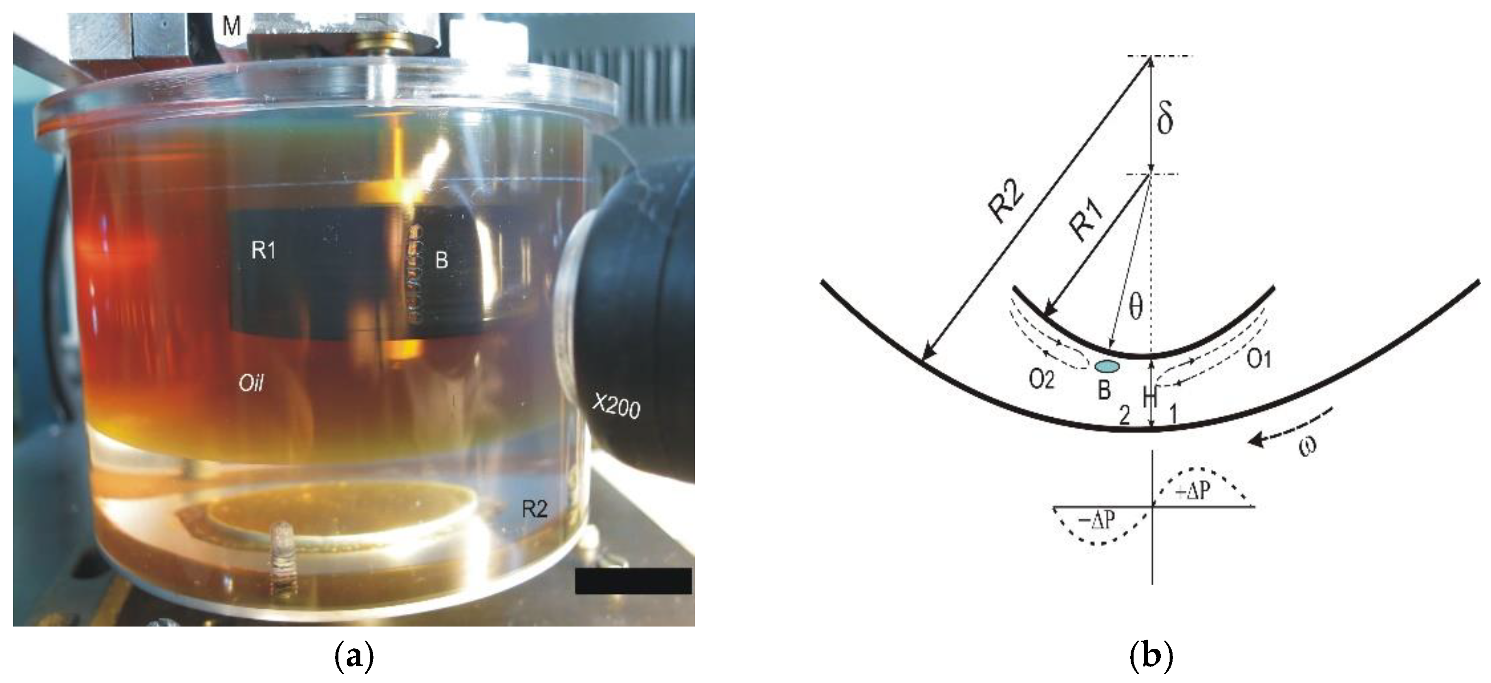
The scheme of the fluid flow between the eccentric cylinders with the inner cylinder’s radius R1 and the outer cylinder’s radius R2 is shown in
Figure 1. The outer cylinder is made of organic glass with an inner diameter of 2∙R1 = 100 mm. The inner cylinders were replaceable and made of ebonite with a diameter of 2∙R2 = 8.5 mm and 50 mm. Silicone oil with a viscosity of 1000 cSt was used as the fluid in these experiments.
The fluid motion was set by the rotation of the outer cylinder with the angular velocity ω. The clearance H between the cylinders was set by the eccentricity δ and is defined as H = R2-R1-δ. A region of flow compression appears in front of the line of a minimum gap; after that, the flow expands, and pressure drops. Cavitation bubbles, marked with the symbol B, are formed at a certain angular distance θ from the line of the minimum gap H. In front of the gas bubbles and behind them, on the surface of the inner cylinder, we could observe reverse flows (O1, O2). An MPXV7007 integrated silicon pressure sensor was used to measure the pressure in the zones of pressure increase and decrease through a 0.5 mm port. The pressure sensor was connected to a port in the inner cylinder, in the middle of the generatrix, through a 15 mm-long tube with the same diameter of 0.5 mm. The fluid did not enter the tube. Each measurement was undertaken for 1 min, and numerous measurements with the same flow parameters showed a total uncertainty of 0.05 mmHg. The pressure sensor was located outside of the cylinders. The inner cylinder could rotate in the sector relative to the minimum clearance line by ±40°.
The pressure plots are shown in
Figure 2. The pressure was measured at a constant angular velocity of the outer cylinder at different values of gap H.
For large values of H = 0.5 mm, there is a slight increase in pressure and a decrease in the expansion region behind line H, curve 1. Reducing the gap to H = 0.3 mm-curve 2 leads to an increase in pressure in the area of flow compression at φ < 90° and a decrease at φ > 90°. Cavitation is observed at a value of H = 0.2 mm, curve 3. A slight steady decrease in the local pressure in the liquid may be sufficient for the occurrence of gaseous cavitation. It can be seen that a pressure drop of only 2% results in cavitation inception and development, which occurs at an angular distance of 7° from the line of minimum clearance downstream. A further decrease in the gap H to 0.1 mm theoretically should lead to a decrease in pressure in the cavitation region. In practice, when flowing around a bubble, the pressure of the dissolved gas in the fluid is greater than the pressure in the gas bubble. The diffusion of gas from the oncoming flow into the bubble leads to the equalization of these pressures to the pressure of the dissolved gas in the fluid. Thus, the oncoming flow will add gas to the original gas bubble until the pressure of the dissolved gas in the liquid equals the pressure in the cavitation bubble.
Figure 3 shows normalized pressure (P
* is atmospheric pressure) in the region of cavitation development for different speeds of the outer cylinder and the size of the gap H between the cylinders. Curves 1,2,3,4 correspond to the speeds of the outer cylinder surface, respectively: 7 mm/s, 10.7 mm/s, 14.8 mm/s, and 21.1 mm/s. It can be seen that pressure changes until H = 0.1 mm when cavitation bubbles develop, and we start capturing pressure inside the bubble. It has been shown that starting from this point, the pressure does not depend on the size of the gap H and the velocity of the outer cylinder and is defined by the pressure of the dissolved gas and vapor mixture in the liquid.
With a slight decrease in the gap between the cylinders, it was found that cavitation at the initial moment arises from a local area but rather quickly develops along the height of the gap between the cylinders.
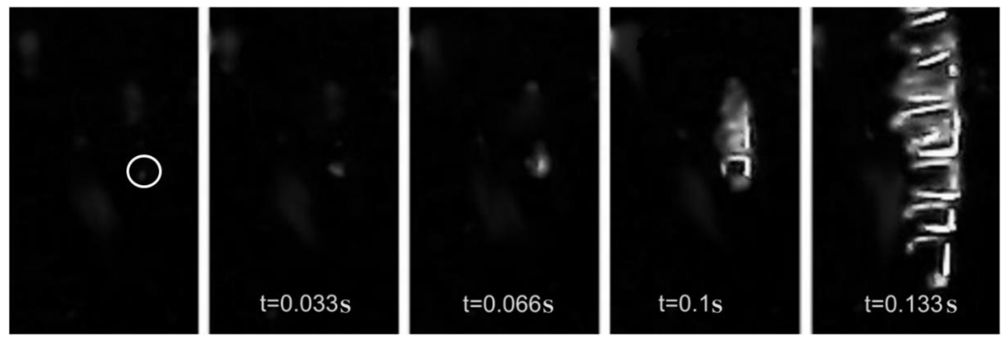
Figure 4 shows the dynamics of cavitation bubble formation on the surface of the inner cylinder with a diameter of 8 mm. At the moment of the formation of the first bubble (circled in the first frame), an electric layer appears on its surface at the liquid–gas interface, which prevents it from uniting with the next bubbles. The charge always arises at the boundary of media with different dielectric permittivity under the influence of the Earth’s electric field.
The recording was conducted at 30 fps using a microscope with a resolution of 640 × 480. All frames are shown without any additional corrections in photo editing software.
The size of the cavitation bubble on frame 5 is about 0.13 mm. The physical size of the bubble was determined from a calibration strip, which, after the experiment, was placed into the gap between the cylinders. The diameter of the outer cylinder made of organic glass is 100 mm, and the size of the cavitation bubble is 0.5 mm or less, which means that it is possible to consider the distortions introduced by the outer cylinder as insignificant due to the small aperture angle of observation. As the ratio of the cylinders’ radii increases, the angular size of the cavitation bubble increases. An increase in the size of the cavitation bubble is associated with the oncoming flow in the region of the minimum gap to the flow between the concentric cylinders.
When the outer cylinder stops, the entire chain of cavitation bubbles floats up in the gap between the cylinders. The presence of a double electric layer at the liquid–gas interface in cavitation bubbles prevents them from merging. In the case of the inequality of gas bubbles in size, a slightly larger bubble rises faster and can overcome the electrostatic repulsion of the upper bubble above itself (
Figure 5).
The bubble merging process is associated with the deformation of their shells and the structure of the electrical double layer in each bubble. The charge redistribution occurs with the phenomenon of electroluminescence (
Figure 5, frames 2–4), and the equilibrium is established after 0.2 s. A new charge distribution arises in the resultant bubble. As noted in [
22], the maximum luminescence intensity in the continuous spectrum during cavitation was observed in the region of 475 nm with a width of ~100 nm.
In the process of cavitation development, which occurs at Re < 1, two return flows were discovered on the surface of the inner cylinder, in front and behind the cavitation bubbles. The return flows develop due to a pressure drop in the cavitation area and the flow of fluid from external regions.
Figure 6 shows frames of an aluminum powder particle tracking in the secondary circulation region ahead of the cavitation chain. In this area, before the line of the minimum gap between the cylinders, the flow is compressed, and part of it goes back along the surface of the inner cylinder, which corresponds to the circulation region O1 in
Figure 1. The cavitation chain is located behind the line of the minimum gap H in the area of flow expansion.
In frame 4 of
Figure 6, it can be seen that the main flow ω switches direction to the opposite along the surface of the inner cylinder (frames 4 to 7). It can be noted that the width of the circulation zone is comparable to the size of the cavitation bubble.
The pressure drop in the cavitation area creates the condition for the occurrence of the second circulation of O2 (
Figure 1) behind the line of the minimum gap H.
In contrast to the first circulation zone in front of line H, the fluid in circulation zone O2 moves along the surface of the inner cylinder to the area with lower pressure, to the cavitation bubble.
Figure 6 shows the trace of a particle moving along the surface of the inner cylinder in the opposite direction of the main fluid flow to the cavitation bubble marked with the symbol B.
As it approaches the chain of cavitation bubbles, the return flow velocity increases and the fluid turns 180° in front of the bubbles chain with increasing speed. Behind the line of minimum clearance, in the area of pressure reduction, a condition is created for the occurrence of secondary circulation.
In experimental studies, flow patterns have been mostly visualized by means of anisotropic aluminum powder. In our case, a reverse-flow near cavitation bubbles chain was discovered by adding a small concentration of aluminum powder to the flow and a recorded the motion on a video camera. When the location of the reverse flow was defined, we added separated particles to the flow to track the particle motion. Knowing the frame rate and cavitation bubble sizes, we could estimate the velocity of the observed particle.
In
Figure 7a, the fluid moves along the surface of the inner cylinder to bubble B with acceleration. Time interval between tracks is ∆t = 0.5 s. In front of the cavitation bubble flow is changing the direction and moves in the direction of the outer cylinder surface rotation (
Figure 7b). The time interval between tracks in
Figure 7b is ∆t = 0.066 s. When the flow changes direction, the speed in the return flow increases to 4.11 mm/s. The linear speed of the outer cylinder is 16 mm/s. As in the area of flow compression, the width of the return circulation region in the area of flow expansion is comparable with the size of the cavitation bubble.


