1. Introduction
A permeable mesh screen in the form of parallel rods, honeycombs, or perforated plates may be used to control flow by changing the direction or scale and intensity of velocity. The most common unsteady flows in industrial applications are in the form of circular motion of liquid (vortex flow) by sudden ejection of a jet from a tube or orifice. Vortex flow is inherently nonlinear and is known to display intriguing behavior while interacting with porous objects. The static properties of porous media have been studied extensively for decades. However, the dynamic interactions of fluids with porous media remains an important area of investigation that can yield critical and much-needed improvements, and benefit a wide set of applications.
The study of vortex flows, their dynamics, and various properties are also an active and ongoing area of research. Some previous studies [
1,
2,
3,
4,
5,
6,
7,
8,
9] conducted experiments to understand the vortex flow interaction with non-porous (flat plate) solid structures. However, with the complicated morphology of porous media, when two subjects of porous media and a vortex ring come together, an even richer set of conditions emerges and displays interesting behavior. Although the two subjects of vortex flows and porous media have been individually investigated, limited studies exist for the propagation of vortex flows through porous media.
Due to the complexity of flow visualization inside solid porous objects, most of the experimental studies have been limited to the interaction of vortex flows and porous screens (thin permeable grids).
Table 1 shows the features of previous studies on vortex ring interaction and porous screens as well as the current study. Adhikari & Lim [
10] experimentally investigated the impact of a liquid vortex (dyed water) ring on solid walls and permeable screens and studied the effects of Reynolds number and porosity of the screens on the vortex expansion while being impinged on a porous screen. The effect of Reynolds number and porosity on flow trajectories were determined. This study used digital particle image velocimetry (DPIV) for the primary vortex visualization. Hrynuk et al. [
11] investigated experimentally the interaction of liquid (dyed water) vortex flow with stainless wired mesh porous screens to study the effect of screen wire dimensions on the flow behavior. The porosity of all porous screens was constant (around 0.64), while their wire diameter varied between 0.018 and 0.267 cm.
Naaktgeboren et al. [
12] studied the interaction of a liquid (dyed water) vortex ring with a thin porous screen experimentally. Using a piston/cylinder vortex ring generator and porous screens with a porosity between 0.44 and 0.79, the authors studied the effect of jet Reynolds number (based on piston velocity) on kinetic energy dissipation. The results of flow pattern and vortex ring trajectory (when interacting with the porous screen) were obtained subject to Reynolds number 3000. Xue et al. [
13] studied laminar vortex ring interaction with porous walls experimentally using the particle image velocimetry (PIV) technique. They applied four in-house-made porous walls with different hole diameters at a constant surface porosity to investigate the influence of the porous wall geometry on the flow features of impinging jets. Bohl et al. [
13] investigated the interaction of vortex rings with thin wire mesh screens using laser-induced fluorescence (LIF) and molecular tagging velocimetry (MTV). They visualized and compared the vortex shedding from individual wires of the porous screens with the prior works. They determined the conditions that affect the porous screen and vortex interaction, such as Reynolds number and screen porosity. Also, the authors of this paper have previously presented an experimental analysis for the interaction of air vortex flow and porous screen [
14]. By comparing trajectories of vortex rings under different Reynolds numbers (Re = 700, 1800, and 3000) and screen open ratios (
= 0.3, 0.6 and 0.8), the author showed the effect of porosity and air injection velocity on the behavior of airflow evolution and secondary vortex formation.
The above review suggests that vortex flows were mainly studied either for a constant porosity or Reynolds number or for primary vortices only. Therefore, the primary aim of this study is to develop a computational model, based on our previous experimental work [
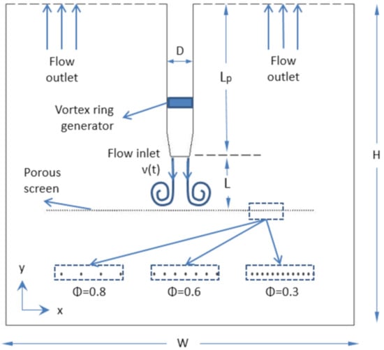
14], to investigate the formation, evolution, and characteristics of the vortical rings with varying conditions, such as porosity, Reynolds number, piston diameter, and working distance. To validate with the experimental results, we reproduce the same scheme in a 3D simulation model in this study to obtain the variables of vortex ring–porous screen interaction, such as kinetic energy and vorticity of vortex rings and flow fields. In addition, with a validated simulation model, we have extended this study to a broad range of applications with various physical parameters, including the diameter of the vortex ring generator and the distance between the generator and the screen. These parameters are not easy to change in the installed experimental setup.
In the area of numerical modelling, Cheng [
15] simulated a vortex ring impacting a permeable wall. Four parameters were varied including porosity (0
1), the dimension of the mesh wire (0.015
0.1), thickness of the porous wall (0.015
1) and Reynolds number of the vortex flow (500
5000). The kinetic energy and vorticity value of the vortex ring flow field were collected. Hassanipour et al. [
16] analytically studied the effect of porous screen properties on vortex ring propagation as well. This study focused on a cubical porous object rather than a thin porous medium. The effect of porosity, permeability, and vortex ring impingement velocity on the flow expansion and contraction in the porous medium was investigated numerically.
The novelty of the current numerical work includes (a) applying the actual geometry of the evenly distributed rods for the porous medium instead of using a solid surface and assigning a porosity and permeability value to the surface, leading to a more accurate analysis of the flow behavior of the vortex ring when passing through the porous screen; (b) investigating the averaged kinetic energy of the vortex rings under different conditions, which provide insights into the future design of mesh screen and porous media in flow control systems; and (c) cross-validation with the experimental results, since all physical parameters in the simulation model mimic the experimental setup. The numerical simulation results are in good agreement with the experimental results, which indicates that our method is reliable for studying vortex dynamics with different porous media under various boundary conditions.
3. Results
3.1. Vortex Ring Generation: Dynamic Mesh Modeling vs. UDF Method
Figure 4 shows the formation and evolution of vortex rings within 0.5 s for both dynamic mesh modeling and the UDF method at a velocity profile of
1800. Left images present vortex rings produced by the dynamic mesh modeling, while the right images are produced by the UDF method. At
0.1 s, a small vortex structure appears at the flow inlet, then it moves downwards and expands. From
0.2 s, it is observed that vorticity is slightly stronger at the core position of the vortex ring in the left images than the one in the right images, while the pattern of the vortex rings is still similar.
3.2. Cross-Validation with Experimental Results
Trajectories of vortex cores (the center of a vortex within a velocity field) generated by two numerical models are captured and compared as shown in
Figure 5.
As a reference, the results of the vortex core trajectory from the experimental work is also mapped in that figure. The results show that when numerical vortex rings are fully formed, the horizontal distance between the vortex core and the axis of symmetry is about two times that of the flow inlet radius, namely, . In comparison, the distance that appeared in the experiment was slightly smaller than . At 0.5 s, vortex cores in all three groups were observed to be at the same location, about to below the vortex generator. Therefore, the formation and evolution of numerical vortex rings from both methods are in good agreement.
The main characteristics of the vortex rings generated by the two methods are similar, as is the flow evolution. It is believed that the two methods have little effect on a further investigation where a porous screen is involved. Therefore, for the rest of the simulation modeling, the UDF method is applied due to its simplicity and the computational cost.
The trajectory of vortex ring interaction with the porous screen, using the UDF method is obtained and compared with the experimental results at Reynolds number (Re = 1800) and time instance (
1.12 s) as shown in
Figure 6. For both porosities of
0.6 and
0.8, the trajectories of the primary vortex ring and the evolution of the transmitted flow in numerical results are in good agreement with the experimental data.
In addition, the traveling time between the vortex impingement until it hits the screen have been computed numerically and validated with the data from experimental work.
Figure 7 shows the evolution of the axial velocity profile below the piston for Re = 1800 and while moving toward the screen. Considering the fact that vortex evolution before hitting the screen does not depend on the porosity of the screen, it can be seen that the hitting instance is around
0.46–0.5 s (
Figure 7b,c) when the three velocity profiles for all porous screens are similar. It is obvious that afterwards (
Figure 7d) the vortex has hit the screen and moves through as the velocity profiles depart for each specific screen porosity. The interaction time of vortex flow and porous media from the simulation modeling is in good agreement with the experimental analysis, which is
0.48 s [
14].
The formation, structure, and position of the vortex ring
before impinging on the screens from simulation modeling were compared and validated with the results from the experiments as shown in
Figure 8. Both snapshots have occurred at the same time instance (
0.48 s) and for the same Reynolds number Re = 1800.
The formation, structure, and position of the vortex ring
after hitting the screen and while propagating through the screen were also cross-validated with experimental data.
Figure 9 shows these comparisons at the same moment (t = 0.66 s) for the same Re = 1800. As observed, the structure and behavior of the vortices while propagating through the screens for all three porosity values are in good agreement with the experimental results. These analyses and comparisons validate the numerical model presented in this study.
3.3. Effect of Porous Screen Open Ratio (Porosity)
In this section, the effect of porosity
on the movement of the vortex ring is investigated. Three cases are considered:
0.3,
0.6 and
0.8. Other conditions such as
1800,
34 mm and
100 mm are kept constant.
Figure 10 shows the effect of porous screen porosity on the flow evolution of the vortex ring. The results show that the interaction between the vortex ring and the porous screen happens between
0.46 s and
0.50 s, as stated in
Section 3.2.
From 0.60 s to 0.70 s, for the fine mesh ( 0.3) case, the vortex ring moves and rotates upon the porous screen forming a clear secondary vortex ring. For the medium mesh ( 0.6) case, the vortex ring tends to transmit the porous screen. A secondary vortex also forms at this moment. For the coarse mesh ( 0.8) case, the majority of the air vortex ring flows downward across the porous screen and the primary vortex ring moves close to the screen surface.
From 0.80 s to 1.00 s, for the fine mesh case, both primary and secondary vortex rings are still rotating upon the porous screen. A small amount of air transmits across the surface and forms a weak vortex structure. For the medium mesh case, the primary vortex ring fully passes across and forms a new vortex structure below the porous screen. The secondary vortex ring shrinks and moves close to the surface. For the coarse mesh case, the primary vortex ring is disrupted by the screen rod and partially reforms the transmitted vortex ring. In the whole process of this case, no clear secondary vortex forms because of the easy transmission of the primary vortex ring.
3.4. Effect of Reynolds Number
To study the effect of Reynolds number on the vortex ring evolution, porosity
is set to be constant, namely,
0.8, as well as
34 mm and
100 mm. Reynolds number is the only different parameter, which alters at
700,
1800 and
3000. In order to produce comparable results, the vortex rings at the same dimensionless time
are compared to each other, where
is defined by Equation (
9).
Figure 11 presents vorticity distribution at different moments. Specifically, vortex rings with different Reynolds numbers, Re = 700, 1800 and 3000, move toward the porous screen, respectively, at t = 1.16, 0.46 and 0.28 s.
In the dimension time scale, the interaction in the three cases begins at
10.6. The value of vorticity at the location of the vortex ring core is different. For vortex rings with injection Reynolds numbers of 700, 1800, and 3000, vorticity values are approximately 50 s
, 150 s
and 250 s
, respectively. This phenomenon follows the relation of flow velocity and vorticity in Equation (
6). At
17.3, namely,
t = 1.90, 0.75, and 0.45 s for each case, it is observed that the transmitted vortex structures in all three groups are in a similar pattern and evolution process.
The average vorticity in the computation domain is obtained at a certain dimensionless time period (
45), as shown in
Figure 12.
is the maximum value of average vorticity for a free vortex flow with respect to Reynolds number. When the vortex ring passes through a fine porous surface (
0.3), fluctuation in the figure happens because of complicated interactions and rebounding of the vortex ring on the porous screen. A higher Reynolds number leads to a larger peak value and a more rapid reduction of average vorticity
. On the other hand, when
0.6 or
0.8, the effect of the Reynolds number on the tendency of average vorticity is not distinct. In other words, in the conditions of medium mesh and coarse mesh, Reynolds number does not have a significant effect on the evolution of average vorticity inside the tank.
The average kinetic energy in the computational domain was also investigated and compared as shown in
Figure 13.
is the maximum value of average kinetic energy for a free vortex. When the porosity is low (
), the trend of kinetic energy is merely affected by the Reynolds number. As the porosity increases and gets coarse (
0.6 and
0.8), the kinetic energy of the vortex ring with a lower Reynolds number falls faster than the one with a higher Reynolds number. In conclusion, Reynolds number plays an important role in the vorticity of a vortex ring when porosity is low. When the porosity is higher, the effect of the Reynolds number is mainly on kinetic energy.
3.5. Effect of Air Outlet Diameter
The piston dimension has an effect on the formation of vortex rings, which results in the flow behavior variation as well. To study these effects, the velocity profile is chosen at a constant rate ( 0.80 m/s), while the diameter of piston varies, 20, 34, and 50 mm. Reynolds number also changes due to the diameter of the air inlet, thus the injection Reynolds numbers of vortex rings impinged from different pistons become 1000, 1800, and 2600 for 20 mm, 34 mm, and 50 mm.
The evolution of vortex rings from different pistons is compared when colliding with the porous screen.
Figure 14 shows the related vorticity contours. The porosity of the porous screen used in the figure is
0.6. The vortex ring generated by a smaller piston passes through the porous screen faster. At
0.60 s, the core of the vortex ring from the small piston (
20 mm) happens close to the porous screen and forms a secondary vortex. Vortex rings from the original piston (
34 mm) and large piston (
50 mm) are still moving towards the porous screen and tend to transmit through it. From
0.80 s to
1.00 s, the primary vortex ring from the small piston has passed through and reforms the transmitted vortex ring. The vortex ring from the large piston almost fully passes through the porous screen but obviously more slowly than in the other two cases. The secondary vortex ring can be observed upon the porous screen. At
1.20 s, it is observed that although broken down by the rods of the porous screen, the primary vortex ring is transmitted and reformed in all three piston diameters.
The effect of piston dimension on the average vorticity of the flow field is presented in
Figure 15. For a smaller piston diameter, the average vorticity reaches its maximum value earlier. Fluctuation appears in all three cases when
0.3, but weakens when the diameter of the piston decreases.
Figure 16 shows the effects of piston dimension on the kinetic energy of the flow field inside the tank within 2 s. The kinetic energy is defined in Equation (
8). The figures show that when the diameter of the piston is larger, the kinetic energy of the vortex rings drops sharply after touching the porous screen. This phenomenon becomes more obvious for smaller
values. It is also observed that when the diameter of the piston is small (
20 mm) and the pores of the surface are large (
0.8), the kinetic energy of the vortex ring has no notable reduction.
3.6. Effect of Distance between Air Inlet and Porous Screen
In this section, the effect of piston–screen distance on the movement of the vortex ring is investigated. Three values of distance are examined,
50, 100, and 150 mm, while the Reynolds number and piston dimension are kept constant at
1800 and
34 mm, respectively. The time that it takes for the vortex ring to touch the surface varies with the distance between the air vortex ring generator and the porous screen.
Figure 17 shows the estimated time when the porous screen begins to affect the vortex ring.
is the mean value of velocity on the surface at 1 mm above the porous screen and
is the one at 1 mm below the porous screen. In the case of the shortest distance
50 mm, at
0.18 s,
increases while
begins to decrease. This phenomenon shows that plenty of mini jets are ejected out of the pores from the surface and rapidly accelerate the lower average velocity. For the distance
100 mm, the interaction appears at
0.46 s, which matches the results of the centerline velocity profiles in
Figure 7. For a long-distance case (
150 mm), the phenomenon happens at
0.66 s.
Figure 18 compares the vortex ring patterns for all three distance cases. When
50 mm, the vortex ring touches the porous screen at
0.18 s before it is fully formed. Secondary vortex rings appear at
0.46 s and
0.66 s. The entire vortex flow, including primary and secondary vortex rings, rapidly transmit through the porous screen at
0.90 s. A comparatively ideal pair of transmitted vortex rings forms after the collision of the primary vortex ring with the porous screen. Vortex rings are fully formed before interaction for cases
100 mm and
150 mm, thus their transmission processes are similar to each other with a time difference of about 0.2 s to 0.3 s. The patterns of vortex flow for
100 mm at
0.66 s and
0.90 s are similar to the ones for
150 mm at
0.90 s and
1.16 s, in which the primary vortex ring transmits through the porous screen and the secondary vortex ring stay upon it. For the case
150 mm, the secondary vortex ring shrinks close to the porous screen and a transmitted vortex ring forms at
1.50 s.
The average vorticity all over the tank is shown in
Figure 19. The computational tank reaches maximum vorticity at different time steps since the interaction of the vortex ring and the porous screen happens at different moments. When
, a short distance (
50 mm) distinctively leads to a rapid fall of vorticity. When
0.6, it can still be observed that the average vorticity decreases a little faster in the case of
50 mm. However, the reduction trends of average vorticity in cases of
50 mm,
100 mm, and
150 mm are almost similar if porosity increases to
. This means that the effect of distance on average vorticity disappears as porosity increases.
Figure 20 shows the average kinetic energy all over the tank in different porosity and screen–piston distance values. When the distance is
50 mm, since the porous screen begins to have an effect on the vortex ring before the ring is fully formed, the maximum value of average kinetic energy is lower than the value for the other two cases and falls sharply. Besides, the results show that for a small porosity value, the effects of distance on kinetic energy are more notable, compared with the porosity values of 0.6 and 0.8. As observed in the figure, the normalized average kinetic energy values become close to each other when porosity increases.
4. Discussion
Numerical simulations of the interaction of vortex rings and porous screens were performed. The effects of porosity
, flow velocity, inlet dimension, and screen distance from the piston on the vortex ring behaviors were investigated.
Table 2 illustrates relevant parameters conducted in the simulations. Results were obtained on velocity, vorticity, and kinetic energy to study the vortex ring structure and flow behavior under different conditions.
It has been concluded in previous sections that the vortex ring touches the porous screen at t = 0.46 s, so the flow field is a free vortex ring before this moment. The vortex ring behaviors after touching the porous screen from both the experimental study and the simulation study are shown in
Figure 9. When
, it is observed that the vortex ring tends to expand horizontally on the screen. In contrast, when
, the vortex ring keeps moving downward vertically and gradually passes the porous screen. More distinguished phenomena appear after t = 0.7 s, as shown in
Figure 10. Air flow, which transmits through the porous screen forms a vortex structure and rotates near the porous screen. When
, the primary vortex ring keeps expanding horizontally and moves closer to the porous screen. A secondary vortex ring is formed. The vortex ring evolution is similar to the experimental phenomenon as stated in [
14]. Hence, the behavior of the vortex ring depends on the porosity of the porous screen. For a coarse porous screen (
0.8), the majority of the vortex ring passes through the screen but little air rebounds from the surface. A weak secondary vortex structure can be observed when the vortex ring collides with the medium-size mesh screen (
0.6). The primary vortex ring rolls and forms secondary vortex rings on the fine mesh (
0.3), while only a small amount of air can transmit. The vortex ring evolution is similar to the experimental phenomena as stated in [
14].
In the experimental study by the authors, ref [
14], Reynolds number was observed to have little effect on the pattern of vortex ring evolution and propagation through the porous medium. Further discussions of the vorticity strength and kinetic energy of vortex rings through numerical analysis are essential in understanding the effect of Reynolds number on the property of vortex flow, as these values are difficult to achieve in experiments. Although a higher Reynolds number leads to a larger peak value and a more rapid reduction of average vorticity, this phenomenon holds similarities among all three different porosities. On the other hand, Reynolds number plays an important role in the average kinetic energy of the free vortex. A higher Reynolds number tends to slow down the drop of average maximum kinetic energy, especially for a medium and coarse mesh. The initial jet Reynolds number plays an unimportant role in the pattern of the vortex ring, but it has a significant influence on the vorticity strength and the kinetic energy. As a result, the vortex rings produced by the synthetic jet at a higher Reynolds number allow for less loss of momentum when passing through the porous screen.
Besides porosity and Reynolds number, the effects of air outlet diameter, and distance between piston and screen on the formation of vortex ring and its kinetic energy are also important for analyzing the interaction of vortex rings and porous screens. With the same velocity profile, a vortex ring generated by a smaller diameter piston ( 50 mm) moves downwards to the porous screen faster and its kinetic energy drops slower. Especially when 20 mm and 0.8, the kinetic energy of the vortex ring barely decreases. In the cases of the varying distance between piston and screen, the kinetic energy value of the computational domain for the shortest distance case ( 50 mm) does not reach as high as other cases ( 100 mm and 150 mm) because the vortex ring touches the screen before becoming fully generated. An earlier collision on the porous screen leads to a greater reduction in the kinetic energy of the vortex ring afterward. The porosity of the porous screen was also considered. When 0.3, an earlier interaction through a shorter distance leads to a smaller kinetic energy at the end. However, the same phenomenon is not exhibited for medium and coarse porosity at 0.6 and 0.8. Therefore, shortening the distance between the piston and the screen reduces the kinetic energy of the vortex ring for a fine porous surface.
5. Conclusions
In this paper we have presented the numerical analysis of vortex flow propagating through the porous screen. The simulation model followed an experimental apparatus including a piston-cylinder vortex ring generator and a permeable mesh. Vortex core trajectories generated by the numerical model were cross-validated and are in good agreement with the results in the experiments. The results were obtained for various physical properties, such as porosity, flow velocity, injection piston diameter, and screen distance from the piston. A porous screen with fine porosity was found to form more vortices compared with medium and coarse porous screens, as more air rebounds from the surface. Therefore, the porosity of the permeable mesh plays a key role in flow control to disrupt vortical structures and achieve a better quality of flow. Keeping the porosity constant and changing the injection velocity, the results showed that increasing the Reynolds number has little effect on the pattern of vortex ring evolution and propagation through the porous medium, but it does affect the kinetic energy dissipation of the vortex wakes, especially for coarse porous screens. For fine porous surfaces, a shorter distance between the piston and the screen leads to a greater reduction in the kinetic energy of the vortex rings. In addition, with a constant inlet air velocity, the kinetic energy related to a smaller piston diameter drops more slowly while propagating through the porous screen. Numerical analysis was helpful to obtain parameters, e.g. kinetic energy variations, that are hard to measure with experimentation.
The limitation of this study is its relation to the single-layer porous medium constructed by a set of evenly arranged rods. Although this model revealed some fundamental relevance to the vortex ring interaction with a permeable screen, it may not be applicable for other porous objects such as packed beds of spheres or porous objects, including several layers of mesh screens.


