
A Beginner’s Guide to the Characterization of Hydrogel Microarchitecture for Cellular Applications

 , , ,
, , ,  , and
, and 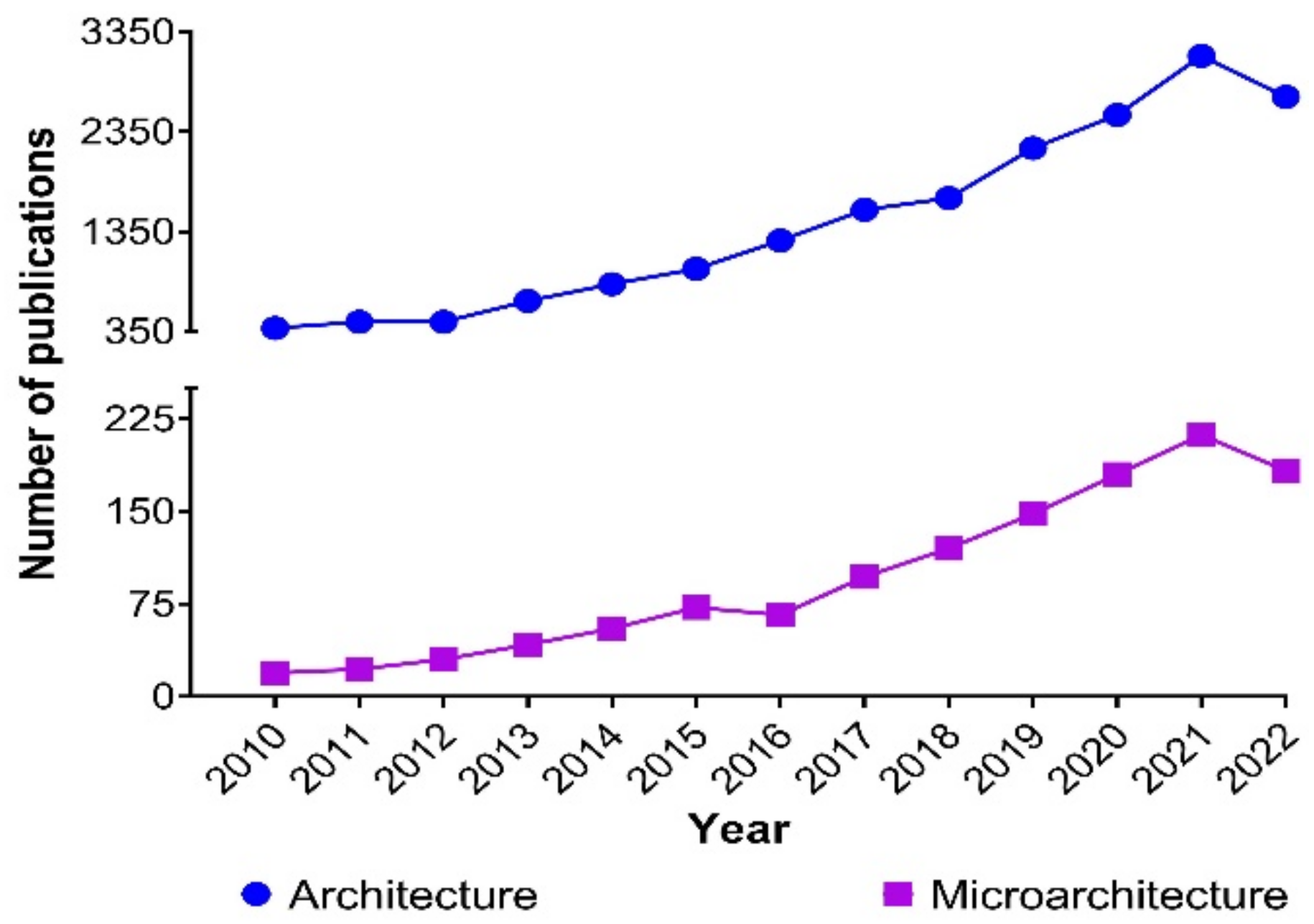
Abstract
:1. Introduction
Hydrogel Microarchitecture
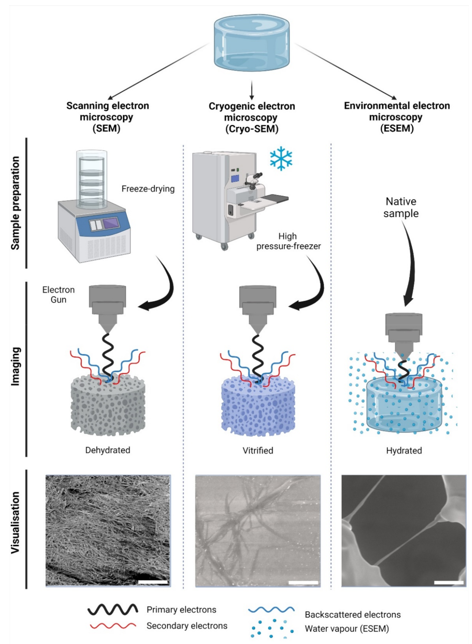
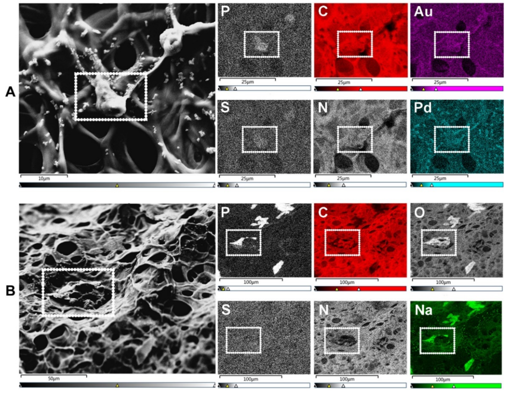
2. Electron-Based Techniques
2.1. Scanning Electron Microscopy
2.2. Cryogenic Scanning Electron Microscopy
2.3. Environmental Scanning Electron Microscopy
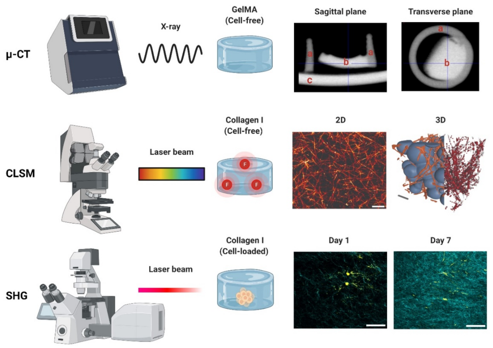
3. Photon-Based Techniques
3.1. Micro-Computed Tomography
3.2. Confocal Laser Scanning Microscopy
3.3. Second Harmonic Generation
3.4. Atomic Force Microscopy
4. Hydrogel Microarchitecture and Cells: Design and Applications
5. Conclusions
Author Contributions
Funding
Institutional Review Board Statement
Informed Consent Statement
Data Availability Statement
Acknowledgments
Conflicts of Interest
Appendix A
References
- Frantz, C.; Stewart, K.M.; Weaver, V.M. The Extracellular Matrix at a Glance. J. Cell Sci. 2010, 123, 4195–4200. [Google Scholar] [CrossRef]
- Couchman, J.R.; Pataki, C.A. An Introduction to Proteoglycans and Their Localization. J. Histochem. Cytochem. 2012, 60, 885–897. [Google Scholar] [CrossRef]
- Pethig, R.; Kell, D.B. The Passive Electrical Properties of Biological Systems: Their Significance in Physiology, Biophysics and Biotechnology. Phys. Med. Biol. 1987, 32, 933–970. [Google Scholar] [CrossRef]
- Ahmed, E.M. Hydrogel: Preparation, Characterization, and Applications: A Review. J. Adv. Res. 2015, 6, 105–121. [Google Scholar] [CrossRef]
- Pita-López, M.L.; Fletes-Vargas, G.; Espinosa-Andrews, H.; Rodríguez-Rodríguez, R. Physically Cross-Linked Chitosan-Based Hydrogels for Tissue Engineering Applications: A State-of-the-Art Review. Eur. Polym. J. 2021, 145, 110176. [Google Scholar] [CrossRef]
- Lang, N.R.; Skodzek, K.; Hurst, S.; Mainka, A.; Steinwachs, J.; Schneider, J.; Aifantis, K.E.; Fabry, B. Biphasic Response of Cell Invasion to Matrix Stiffness in Three-Dimensional Biopolymer Networks. Acta Biomater. 2015, 13, 61–67. [Google Scholar] [CrossRef]
- Paszek, M.J.; Zahir, N.; Johnson, K.R.; Lakins, J.N.; Rozenberg, G.I.; Gefen, A.; Reinhart-King, C.A.; Margulies, S.S.; Dembo, M.; Boettiger, D.; et al. Tensional Homeostasis and the Malignant Phenotype. Cancer Cell 2005, 8, 241–254. [Google Scholar] [CrossRef]
- Li, Y.; Kilian, K.A. Bridging the Gap: From 2D Cell Culture to 3D Microengineered Extracellular Matrices. Adv. Healthc. Mater. 2015, 4, 2780–2796. [Google Scholar] [CrossRef] [PubMed]
- Tibbitt, M.W.; Anseth, K.S. Hydrogels as Extracellular Matrix Mimics for 3D Cell Culture. Biotechnol. Bioeng. 2009, 103, 655–663. [Google Scholar] [CrossRef]
- Tsou, Y.H.; Khoneisser, J.; Huang, P.C.; Xu, X. Hydrogel as a Bioactive Material to Regulate Stem Cell Fate. Bioact. Mater. 2016, 1, 39–55. [Google Scholar] [CrossRef] [Green Version]
- Ruedinger, F.; Lavrentieva, A.; Blume, C.; Pepelanova, I.; Scheper, T. Hydrogels for 3D Mammalian Cell Culture: A Starting Guide for Laboratory Practice. Appl. Microbiol. Biotechnol. 2015, 99, 623–636. [Google Scholar] [CrossRef]
- Stanton, M.M.; Samitier, J.; Sánchez, S. Bioprinting of 3D Hydrogels. Lab A Chip 2015, 15, 3111–3115. [Google Scholar] [CrossRef] [PubMed]
- Kim, H.-D.; Guo, T.W.; Wu, A.P.; Wells, A.; Gertler, F.B.; Lauffenburger, D.A. Epidermal Growth Factor–Induced Enhancement of Glioblastoma Cell Migration in 3D Arises from an Intrinsic Increase in Speed But an Extrinsic Matrix- and Proteolysis-Dependent Increase in Persistence. Mol. Biol. Cell 2008, 19, 4249–4259. [Google Scholar] [CrossRef] [PubMed]
- De Hilster, R.H.J.; Sharma, P.K.; Jonker, M.R.; White, E.S.; Gercama, E.A.; Roobeek, M.; Timens, W.; Harmsen, M.C.; Hylkema, M.N.; Burgess, J.K. Human Lung Extracellular Matrix Hydrogels Resemble the Stiffness and Viscoelasticity of Native Lung Tissue. Am. J. Physiol. -Lung Cell. Mol. Physiol. 2020, 318, L698–L704. [Google Scholar] [CrossRef] [PubMed]
- Liguori, G.R.; Liguori, T.T.A.; de Moraes, S.R.; Sinkunas, V.; Terlizzi, V.; van Dongen, J.A.; Sharma, P.K.; Moreira, L.F.P.; Harmsen, M.C. Molecular and Biomechanical Clues From Cardiac Tissue Decellularized Extracellular Matrix Drive Stromal Cell Plasticity. Front. Bioeng. Biotechnol. 2020, 8, 520. [Google Scholar] [CrossRef]
- Dongen, J.A.; Getova, V.; Brouwer, L.A.; Liguori, G.R.; Sharma, P.K.; Stevens, H.P.; Lei, B.; Harmsen, M.C. Adipose Tissue-derived Extracellular Matrix Hydrogels as a Release Platform for Secreted Paracrine Factors. J. Tissue Eng. Regen. Med. 2019, 13, 973–985. [Google Scholar] [CrossRef]
- Freytes, D.O.; Martin, J.; Velankar, S.S.; Lee, A.S.; Badylak, S.F. Preparation and Rheological Characterization of a Gel Form of the Porcine Urinary Bladder Matrix. Biomaterials 2008, 29, 1630–1637. [Google Scholar] [CrossRef]
- Sackett, S.D.; Tremmel, D.M.; Ma, F.; Feeney, A.K.; Maguire, R.M.; Brown, M.E.; Zhou, Y.; Li, X.; O’Brien, C.; Li, L.; et al. Extracellular Matrix Scaffold and Hydrogel Derived from Decellularized and Delipidized Human Pancreas. Sci. Rep. 2018, 8, 10452. [Google Scholar] [CrossRef]
- Catoira, M.C.; Fusaro, L.; Di Francesco, D.; Ramella, M.; Boccafoschi, F. Overview of Natural Hydrogels for Regenerative Medicine Applications. J. Mater. Sci. Mater. Med. 2019, 30, 115. [Google Scholar] [CrossRef]
- Martinez-Garcia, F.D.; de Hilster, R.H.J.; Sharma, P.K.; Borghuis, T.; Hylkema, M.N.; Burgess, J.K.; Harmsen, M.C. Architecture and Composition Dictate Viscoelastic Properties of Organ-Derived Extracellular Matrix Hydrogels. Polymers 2021, 13, 3113. [Google Scholar] [CrossRef]
- Wang, Y.; Zhao, Q.; Zhang, H.; Yang, S.; Jia, X. A Novel Poly(Amido Amine)-Dendrimer-Based Hydrogel as a Mimic for the Extracellular Matrix. Adv. Mater. 2014, 26, 4163–4167. [Google Scholar] [CrossRef] [PubMed]
- Collier, J.H.; Segura, T. Evolving the Use of Peptides as Components of Biomaterials. Biomaterials 2011, 32, 4198–4204. [Google Scholar] [CrossRef] [PubMed]
- Ki, C.S.; Lin, T.-Y.; Korc, M.; Lin, C.-C. Thiol-Ene Hydrogels as Desmoplasia-Mimetic Matrices for Modeling Pancreatic Cancer Cell Growth, Invasion, and Drug Resistance. Biomaterials 2014, 35, 9668–9677. [Google Scholar] [CrossRef] [PubMed]
- Krishnamoorthy, S.; Noorani, B.; Xu, C. Effects of Encapsulated Cells on the Physical–Mechanical Properties and Microstructure of Gelatin Methacrylate Hydrogels. Int. J. Mol. Sci. 2019, 20, 5061. [Google Scholar] [CrossRef] [PubMed]
- Loessner, D.; Meinert, C.; Kaemmerer, E.; Martine, L.C.; Yue, K.; Levett, P.A.; Klein, T.J.; Melchels, F.P.W.; Khademhosseini, A.; Hutmacher, D.W. Functionalization, Preparation and Use of Cell-Laden Gelatin Methacryloyl-Based Hydrogels as Modular Tissue Culture Platforms. Nat. Protoc. 2016, 11, 727–746. [Google Scholar] [CrossRef] [PubMed]
- Yoon, H.J.; Shin, S.R.; Cha, J.M.; Lee, S.H.; Kim, J.H.; Do, J.T.; Song, H.; Bae, H. Cold Water Fish Gelatin Methacryloyl Hydrogel for Tissue Engineering Application. PLoS ONE 2016, 11, 1–18. [Google Scholar] [CrossRef]
- Li, X.; Zhang, J.; Kawazoe, N.; Chen, G. Fabrication of Highly Crosslinked Gelatin Hydrogel and Its Influence on Chondrocyte Proliferation and Phenotype. Polymers 2017, 9, 309. [Google Scholar] [CrossRef]
- Kessler, L.; Gehrke, S.; Winnefeld, M.; Huber, B.; Hoch, E.; Walter, T.; Wyrwa, R.; Schnabelrauch, M.; Schmidt, M.; Kückelhaus, M.; et al. Methacrylated Gelatin/Hyaluronan-Based Hydrogels for Soft Tissue Engineering. J. Tissue Eng. 2017, 8, 204173141774415. [Google Scholar] [CrossRef]
- Camci-Unal, G.; Cuttica, D.; Annabi, N.; Demarchi, D.; Khademhosseini, A. Synthesis and Characterization of Hybrid Hyaluronic Acid-Gelatin Hydrogels. Biomacromolecules 2013, 14, 1085–1092. [Google Scholar] [CrossRef]
- Sun, M.; Sun, X.; Wang, Z.; Guo, S.; Yu, G.; Yang, H. Synthesis and Properties of Gelatin Methacryloyl (GelMA) Hydrogels and Their Recent Applications in Load-Bearing Tissue. Polymers 2018, 10, 1290. [Google Scholar] [CrossRef] [Green Version]
- Yin, J.; Yan, M.; Wang, Y.; Fu, J.; Suo, H. 3D Bioprinting of Low-Concentration Cell-Laden Gelatin Methacrylate (GelMA) Bioinks with a Two-Step Cross-Linking Strategy. ACS Appl. Mater. Interfaces 2018, 10, 6849–6857. [Google Scholar] [CrossRef] [PubMed]
- Pepelanova, I.; Kruppa, K.; Scheper, T.; Lavrentieva, A. Gelatin-Methacryloyl (GelMA) Hydrogels with Defined Degree of Functionalization as a Versatile Toolkit for 3D Cell Culture and Extrusion Bioprinting. Bioengineering 2018, 5, 55. [Google Scholar] [CrossRef] [PubMed]
- Madduma-Bandarage, U.S.K.; Madihally, S.V. Synthetic Hydrogels: Synthesis, Novel Trends, and Applications. J. Appl. Polym. Sci. 2021, 138, 50376. [Google Scholar] [CrossRef]
- Chaudhuri, O.; Gu, L.; Klumpers, D.; Darnell, M.; Bencherif, S.A.; Weaver, J.C.; Huebsch, N.; Lee, H.; Lippens, E.; Duda, G.N.; et al. Hydrogels with Tunable Stress Relaxation Regulate Stem Cell Fate and Activity. Nat. Mater. 2015, 15, 326. [Google Scholar] [CrossRef] [PubMed]
- Chaudhuri, O.; Gu, L.; Darnell, M.; Klumpers, D.; Bencherif, S.A.; Weaver, J.C.; Huebsch, N.; Mooney, D.J. Substrate Stress Relaxation Regulates Cell Spreading. Nat. Commun. 2015, 6, 6365. [Google Scholar] [CrossRef]
- Wisdom, K.M.; Adebowale, K.; Chang, J.; Lee, J.Y.; Nam, S.; Desai, R.; Rossen, N.S.; Rafat, M.; West, R.B.; Hodgson, L.; et al. Matrix Mechanical Plasticity Regulates Cancer Cell Migration through Confining Microenvironments. Nat. Commun. 2018, 9, 4144. [Google Scholar] [CrossRef]
- Laronda, M.M.; Rutz, A.L.; Xiao, S.; Whelan, K.A.; Duncan, F.E.; Roth, E.W.; Woodruff, T.K.; Shah, R.N. A Bioprosthetic Ovary Created Using 3D Printed Microporous Scaffolds Restores Ovarian Function in Sterilized Mice. Nat. Commun. 2017, 8, 15261. [Google Scholar] [CrossRef]
- Park, S.-N.; Park, J.-C.; Kim, H.O.; Song, M.J.; Suh, H. Characterization of Porous Collagen/Hyaluronic Acid Scaffold Modified by 1-Ethyl-3-(3-Dimethylaminopropyl)Carbodiimide Cross-Linking. Biomaterials 2002, 23, 1205–1212. [Google Scholar] [CrossRef]
- Caliari, S.R.; Burdick, J.A. A Practical Guide to Hydrogels for Cell Culture. Nat. Methods 2016, 13, 405–414. [Google Scholar] [CrossRef]
- Karageorgiou, V.; Kaplan, D. Porosity of 3D Biomaterial Scaffolds and Osteogenesis. Biomaterials 2005, 26, 5474–5491. [Google Scholar] [CrossRef]
- León y León, C.A. New Perspectives in Mercury Porosimetry. Adv. Colloid Interface Sci. 1998, 76–77, 341–372. [Google Scholar] [CrossRef]
- Fischer, T.; Hayn, A.; Mierke, C.T. Fast and Reliable Advanced Two-Step Pore-Size Analysis of Biomimetic 3D Extracellular Matrix Scaffolds. Sci. Rep. 2019, 9, 8352. [Google Scholar] [CrossRef] [PubMed]
- Doyle, A.D.; Carvajal, N.; Jin, A.; Matsumoto, K.; Yamada, K.M. Local 3D Matrix Microenvironment Regulates Cell Migration through Spatiotemporal Dynamics of Contractility-Dependent Adhesions. Nat. Commun. 2015, 6, 8720. [Google Scholar] [CrossRef] [PubMed]
- Takahashi, Y.; Tabata, Y. Effect of the Fiber Diameter and Porosity of Non-Woven PET Fabrics on the Osteogenic Differentiation of Mesenchymal Stem Cells. J. Biomater. Sci. Polym. Ed. 2004, 15, 41–57. [Google Scholar] [CrossRef]
- Roosa, S.M.M.; Kemppainen, J.M.; Moffitt, E.N.; Krebsbach, P.H.; Hollister, S.J. The Pore Size of Polycaprolactone Scaffolds Has Limited Influence on Bone Regeneration in an in Vivo Model. J. Biomed. Mater. Res. 2010, 92A, 359–368. [Google Scholar] [CrossRef]
- Ho, S.T.; Hutmacher, D.W. A Comparison of Micro CT with Other Techniques Used in the Characterization of Scaffolds. Biomaterials 2006, 27, 1362–1376. [Google Scholar] [CrossRef]
- Kuboki, Y.; Takita, H.; Kobayashi, D.; Tsuruga, E.; Inoue, M.; Murata, M.; Nagai, N.; Dohi, Y.; Ohgushi, H. BMP-Induced Osteogenesis on the Surface of Hydroxyapatite with Geometrically Feasible and Nonfeasible Structures: Topology of Osteogenesis. J. Biomed. Mater. Res. 1998, 39, 190–199. [Google Scholar] [CrossRef]
- Lien, S.-M.; Ko, L.-Y.; Huang, T.-J. Effect of Pore Size on ECM Secretion and Cell Growth in Gelatin Scaffold for Articular Cartilage Tissue Engineering. Acta Biomater. 2009, 5, 670–679. [Google Scholar] [CrossRef]
- Mikos, A.G.; Sarakinos, G.; Lyman, M.D.; Ingber, D.E.; Vacanti, J.P.; Langer, R. Prevascularization of Porous Biodegradable Polymers. Biotechnol. Bioeng. 1993, 42, 716–723. [Google Scholar] [CrossRef]
- Chang, Y.-S.; Gu, H.-O.; Kobayashi, M.; Oka, M. Influence of Various Structure Treatments on Histological Fixation of Titanium Implants. J. Arthroplast. 1998, 13, 816–825. [Google Scholar] [CrossRef]
- Steflik, D.E.; Corpe, R.S.; Young, T.R.; Sisk, A.L.; Parr, G.R. The Biologic Tissue Responses to Uncoated and Coated Implanted Biomaterials. Adv. Dent. Res. 1999, 13, 27–33. [Google Scholar] [CrossRef] [PubMed]
- Yuan, H.; Kurashina, K.; de Bruijn, J.D.; Li, Y.; de Groot, K.; Zhang, X. A Preliminary Study on Osteoinduction of Two Kinds of Calcium Phosphate Ceramics. Biomaterials 1999, 20, 1799–1806. [Google Scholar] [CrossRef]
- Freed, L.E.; Vunjak-Novakovic, G.; Biron, R.J.; Eagles, D.B.; Lesnoy, D.C.; Barlow, S.K.; Langer, R. Biodegradable Polymer Scaffolds for Tissue Engineering. Nat. Biotechnol. 1994, 12, 689–693. [Google Scholar] [CrossRef] [PubMed]
- Stein, A.M.; Vader, D.A.; Jawerth, L.M.; Weitz, D.A.; Sander, L.M. An Algorithm for Extracting the Network Geometry of Three-Dimensional Collagen Gels. J. Microsc. 2008, 232, 463–475. [Google Scholar] [CrossRef]
- Xu, T.; Vavylonis, D.; Tsai, F.-C.; Koenderink, G.H.; Nie, W.; Yusuf, E.; Lee, I.-J.; Wu, J.-Q.; Huang, X. SOAX: A Software for Quantification of 3D Biopolymer Networks. Sci. Rep. 2015, 5, 9081. [Google Scholar] [CrossRef] [PubMed]
- Franke, K.; Sapudom, J.; Kalbitzer, L.; Anderegg, U.; Pompe, T. Topologically Defined Composites of Collagen Types I and V as in Vitro Cell Culture Scaffolds. Acta Biomater. 2014, 10, 2693–2702. [Google Scholar] [CrossRef]
- Hayn, A.; Fischer, T.; Mierke, C.T. Inhomogeneities in 3D Collagen Matrices Impact Matrix Mechanics and Cancer Cell Migration. Front. Cell Dev. Biol. 2020, 8, 593879. [Google Scholar] [CrossRef]
- Sapudom, J.; Rubner, S.; Martin, S.; Kurth, T.; Riedel, S.; Mierke, C.T.; Pompe, T. The Phenotype of Cancer Cell Invasion Controlled by Fibril Diameter and Pore Size of 3D Collagen Networks. Biomaterials 2015, 52, 367–375. [Google Scholar] [CrossRef]
- Fischer, T.; Wilharm, N.; Hayn, A.; Mierke, C.T. Matrix and Cellular Mechanical Properties Are the Driving Factors for Facilitating Human Cancer Cell Motility into 3D Engineered Matrices. Converg. Sci. Phys. Oncol. 2017, 3, 044003. [Google Scholar] [CrossRef]
- Kunschmann, T.; Puder, S.; Fischer, T.; Steffen, A.; Rottner, K.; Mierke, C.T. The Small GTPase Rac1 Increases Cell Surface Stiffness and Enhances 3D Migration Into Extracellular Matrices. Sci. Rep. 2019, 9, 7675. [Google Scholar] [CrossRef] [Green Version]
- Mierke, C.T.; Fischer, T.; Puder, S.; Kunschmann, T.; Soetje, B.; Ziegler, W.H. Focal Adhesion Kinase Activity Is Required for Actomyosin Contractility-Based Invasion of Cells into Dense 3D Matrices. Sci. Rep. 2017, 7, 42780. [Google Scholar] [CrossRef] [PubMed]
- Fischer, T.; Hayn, A.; Mierke, C.T. Effect of Nuclear Stiffness on Cell Mechanics and Migration of Human Breast Cancer Cells. Front. Cell Dev. Biol. 2020, 8, 393. [Google Scholar] [CrossRef] [PubMed]
- Chen, Y.; Lin, R.; Qi, H.; Yang, Y.; Bae, H.; Melero-Martin, J.M.; Khademhosseini, A. Functional Human Vascular Network Generated in Photocrosslinkable Gelatin Methacrylate Hydrogels. Adv. Funct. Mater. 2012, 22, 2027–2039. [Google Scholar] [CrossRef]
- Toki, F.; Honkura, N.; Shirakata, Y.; Imamura, T.; Higashiyama, S.; Nanba, D. Second Harmonic Generation Reveals Collagen Fibril Remodeling in Fibroblast-Populated Collagen Gels. Cell Struct. Funct. 2013, 38, 229–238. [Google Scholar] [CrossRef] [PubMed]
- De Vicente, G.; Lensen, M.C. Topographically and Elastically Micropatterned PEG-Based Hydrogels to Control Cell Adhesion and Migration. Eur. Polym. J. 2016, 78, 290–301. [Google Scholar] [CrossRef]
- Almonacid Suarez, A.M.; van der Ham, I.; Brinker, M.G.L.; van Rijn, P.; Harmsen, M.C. Topography-Driven Alterations in Endothelial Cell Phenotype and Contact Guidance. Heliyon 2020, 6, e04329. [Google Scholar] [CrossRef]
- Al-Haque, S.; Miklas, J.W.; Feric, N.; Chiu, L.L.Y.; Chen, W.L.K.; Simmons, C.A.; Radisic, M. Hydrogel Substrate Stiffness and Topography Interact to Induce Contact Guidance in Cardiac Fibroblasts. Macromol. Biosci. 2012, 12, 1342–1353. [Google Scholar] [CrossRef]
- Almonacid Suarez, A.M.; Brinker, M.G.L.; Brouwer, L.A.; van der Ham, I.; Harmsen, M.C.; van Rijn, P. Topography-Mediated Myotube and Endothelial Alignment, Differentiation, and Extracellular Matrix Organization for Skeletal Muscle Engineering. Polymers 2020, 12, 1948. [Google Scholar] [CrossRef]
- Almonacid Suarez, A.M.; Zhou, Q.; Rijn, P.; Harmsen, M.C. Directional Topography Gradients Drive Optimum Alignment and Differentiation of Human Myoblasts. J. Tissue Eng. Regen. Med. 2019, 13, 2234–2245. [Google Scholar] [CrossRef]
- Chavda, H.; Modhia, I.; Patel, R.; Patel, C. Preparation and Characterization of Superporous Hydrogel Based on Different Polymers. Int. J. Pharm. Investig. 2012, 2, 134. [Google Scholar] [CrossRef] [Green Version]
- Van Vlierberghe, S.; Cnudde, V.; Dubruel, P.; Masschaele, B.; Cosijns, A.; de Paepe, I.; Jacobs, P.J.S.; van Hoorebeke, L.; Remon, J.P.; Schacht, E. Porous Gelatin Hydrogels: 1. Cryogenic Formation and Structure Analysis. Biomacromolecules 2007, 8, 331–337. [Google Scholar] [CrossRef]
- Xiao, W.; He, J.; Nichol, J.W.; Wang, L.; Hutson, C.B.; Wang, B.; Du, Y.; Fan, H.; Khademhosseini, A. Synthesis and Characterization of Photocrosslinkable Gelatin and Silk Fibroin Interpenetrating Polymer Network Hydrogels. Acta Biomater. 2011, 7, 2384–2393. [Google Scholar] [CrossRef]
- Choi, S.-W.; Xie, J.; Xia, Y. Chitosan-Based Inverse Opals: Three-Dimensional Scaffolds with Uniform Pore Structures for Cell Culture. Adv. Mater. 2009, 21, 2997–3001. [Google Scholar] [CrossRef]
- Eke, G.; Mangir, N.; Hasirci, N.; MacNeil, S.; Hasirci, V. Development of a UV Crosslinked Biodegradable Hydrogel Containing Adipose Derived Stem Cells to Promote Vascularization for Skin Wounds and Tissue Engineering. Biomaterials 2017, 129, 188–198. [Google Scholar] [CrossRef]
- Habib, A.; Sathish, V.; Mallik, S.; Khoda, B. 3D Printability of Alginate-Carboxymethyl Cellulose Hydrogel. Materials 2018, 11, 454. [Google Scholar] [CrossRef]
- Jia, W.; Gungor-Ozkerim, P.S.; Zhang, Y.S.; Yue, K.; Zhu, K.; Liu, W.; Pi, Q.; Byambaa, B.; Dokmeci, M.R.; Shin, S.R.; et al. Direct 3D Bioprinting of Perfusable Vascular Constructs Using a Blend Bioink. Biomaterials 2016, 106, 58–68. [Google Scholar] [CrossRef]
- Koch, M.; Włodarczyk-Biegun, M.K. Faithful Scanning Electron Microscopic (SEM) Visualization of 3D Printed Alginate-Based Scaffolds. Bioprinting 2020, 20, e00098. [Google Scholar] [CrossRef]
- Doucet, F.J.; Lead, J.R.; Maguire, L.; Achterberg, E.P.; Millward, G.E. Visualisation of Natural Aquatic Colloids and Particles–A Comparison of Conventional High Vacuum and Environmental Scanning Electron Microscopy. J. Environ. Monitor. 2005, 7, 115. [Google Scholar] [CrossRef]
- Donald, A.M. The Use of Environmental Scanning Electron Microscopy for Imaging Wet and Insulating Materials. Nat. Mater. 2003, 2, 511–516. [Google Scholar] [CrossRef]
- Zheng, H.; Tian, W.; Yan, H.; Yue, L.; Zhang, Y.; Han, F.; Chen, X.; Li, Y. Rotary Culture Promotes the Proliferation of MCF-7 Cells Encapsulated in Three-Dimensional Collagen–Alginate Hydrogels via Activation of the ERK1/2-MAPK Pathway. Biomed. Mater. 2012, 7, 015003. [Google Scholar] [CrossRef]
- Liang, R.; Yang, G.; Kim, K.E.; D’Amore, A.; Pickering, A.N.; Zhang, C.; Woo, S.L.-Y. Positive Effects of an Extracellular Matrix Hydrogel on Rat Anterior Cruciate Ligament Fibroblast Proliferation and Collagen MRNA Expression. J. Orthop. Transl. 2015, 3, 114–122. [Google Scholar] [CrossRef]
- Eslami, M.; Vrana, N.E.; Zorlutuna, P.; Sant, S.; Jung, S.; Masoumi, N.; Khavari-Nejad, R.A.; Javadi, G.; Khademhosseini, A. Fiber-Reinforced Hydrogel Scaffolds for Heart Valve Tissue Engineering. J. Biomater. Appl. 2014, 29, 399–410. [Google Scholar] [CrossRef]
- Zhong, X.; Ji, C.; Chan, A.K.L.; Kazarian, S.G.; Ruys, A.; Dehghani, F. Fabrication of Chitosan/Poly(ε-Caprolactone) Composite Hydrogels for Tissue Engineering Applications. J. Mater. Sci. Mater. Med. 2011, 22, 279–288. [Google Scholar] [CrossRef]
- Patiño Vargas, M.I.; Martinez-Garcia, F.D.; Offens, F.; Becerra, N.Y.; Restrepo, L.M.; van der Mei, H.C.; Harmsen, M.C.; van Kooten, T.G.; Sharma, P.K. Viscoelastic Properties of Plasma-Agarose Hydrogels Dictate Favorable Fibroblast Responses for Skin Tissue Engineering Applications. Biomater. Adv. 2022, 139, 212967. [Google Scholar] [CrossRef]
- Sattari, S.; Dadkhah Tehrani, A.; Adeli, M. PH-Responsive Hybrid Hydrogels as Antibacterial and Drug Delivery Systems. Polymers 2018, 10, 660. [Google Scholar] [CrossRef]
- Vilela, P.B.; Dalalibera, A.; Becegato, V.A.; Paulino, A.T. Single-Component and Multi-Component Metal Abatement in Water Using a Hydrogel Based on Chitosan: Characterization, Isotherm, Kinetic, and Thermodynamic Results. Water Air Soil Pollut. 2020, 231, 507. [Google Scholar] [CrossRef]
- Guven, M.N.; Seckin Altuncu, M.; Demir Duman, F.; Eren, T.N.; Yagci Acar, H.; Avci, D. Bisphosphonate-Functionalized Poly(β-Amino Ester) Network Polymers. J. Biomed. Mater. Res. 2017, 105, 1412–1421. [Google Scholar] [CrossRef]
- Ha, J.H.; Lim, J.H.; Kim, J.W.; Cho, H.-Y.; Jo, S.G.; Lee, S.H.; Eom, J.Y.; Lee, J.M.; Chung, B.G. Conductive GelMA–Collagen–AgNW Blended Hydrogel for Smart Actuator. Polymers 2021, 13, 1217. [Google Scholar] [CrossRef]
- Scimeca, M.; Bischetti, S.; Lamsira, H.K.; Bonfiglio, R.; Bonanno, E. Energy Dispersive X-Ray (EDX) Microanalysis: A Powerful Tool in Biomedical Research and Diagnosis. Eur. J. Histochem. 2018, 62, 2841. [Google Scholar] [CrossRef]
- Nichol, J.W.; Koshy, S.T.; Bae, H.; Hwang, C.M.; Yamanlar, S.; Khademhosseini, A. Cell-Laden Microengineered Gelatin Methacrylate Hydrogels. Biomaterials 2010, 31, 5536–5544. [Google Scholar] [CrossRef] [Green Version]
- Martinez-Garcia, F.D.; Valk, M.M.; Sharma, P.K.; Burgess, J.K.; Harmsen, M.C. Adipose Tissue-Derived Stromal Cells Alter the Mechanical Stability and Viscoelastic Properties of Gelatine Methacryloyl Hydrogels. IJMS 2021, 22, 10153. [Google Scholar] [CrossRef]
- Chimenti, I.; Rizzitelli, G.; Gaetani, R.; Angelini, F.; Ionta, V.; Forte, E.; Frati, G.; Schussler, O.; Barbetta, A.; Messina, E.; et al. Human Cardiosphere-Seeded Gelatin and Collagen Scaffolds as Cardiogenic Engineered Bioconstructs. Biomaterials 2011, 32, 9271–9281. [Google Scholar] [CrossRef]
- McKinlay, K.J.; Allison, F.J.; Scotchford, C.A.; Grant, D.M.; Oliver, J.M.; King, J.R.; Wood, J.V.; Brown, P.D. Comparison of Environmental Scanning Electron Microscopy with High Vacuum Scanning Electron Microscopy as Applied to the Assessment of Cell Morphology. J. Biomed. Mater. Res. 2004, 69, 359–366. [Google Scholar] [CrossRef]
- Bokstad, M.; Medalia, O. Correlative Light Electron Microscopy as a Navigating Tool for Cryo-Electron Tomography Analysis. In Fluorescence Microscopy; Elsevier: Amsterdam, The Netherlands, 2014; pp. 121–131. ISBN 978-0-12-409513-7. [Google Scholar]
- Aston, R.; Sewell, K.; Klein, T.; Lawrie, G.; Grøndahl, L. Evaluation of the Impact of Freezing Preparation Techniques on the Characterisation of Alginate Hydrogels by Cryo-SEM. Eur. Polym. J. 2016, 82, 1–15. [Google Scholar] [CrossRef]
- Kuleshova, L.L.; Gouk, S.S.; Hutmacher, D.W. Vitrification as a Prospect for Cryopreservation of Tissue-Engineered Constructs. Biomaterials 2007, 28, 1585–1596. [Google Scholar] [CrossRef]
- Tavukcuoglu, S.; Al-Azawi, T.; Khaki, A.A.; Al-Hasani, S. Is Vitrification Standard Method of Cryopreservation. Middle East Fertil. Soc. J. 2012, 17, 152–156. [Google Scholar] [CrossRef]
- Ivan’kova, E.M.; Dobrovolskaya, I.P.; Popryadukhin, P.V.; Kryukov, A.; Yudin, V.E.; Morganti, P. In-Situ Cryo-SEM Investigation of Porous Structure Formation of Chitosan Sponges. Polym. Test. 2016, 52, 41–45. [Google Scholar] [CrossRef]
- Ji, C.; Annabi, N.; Khademhosseini, A.; Dehghani, F. Fabrication of Porous Chitosan Scaffolds for Soft Tissue Engineering Using Dense Gas CO2. Acta Biomater. 2011, 7, 1653–1664. [Google Scholar] [CrossRef]
- Schnabel-Lubovsky, M.; Kossover, O.; Melino, S.; Nanni, F.; Talmon, Y.; Seliktar, D. Visualizing Cell-laden Fibrin-based Hydrogels Using Cryogenic Scanning Electron Microscopy and Confocal Microscopy. J. Tissue Eng. Regen. Med. 2019, 13, 587–598. [Google Scholar] [CrossRef]
- Valot, L.; Maumus, M.; Brunel, L.; Martinez, J.; Amblard, M.; Noël, D.; Mehdi, A.; Subra, G. A Collagen-Mimetic Organic-Indorganic Hydrogel for Cartilage Engineering. Gels 2021, 7, 73. [Google Scholar] [CrossRef]
- Pan, T.; Song, W.; Cao, X.; Wang, Y. 3D Bioplotting of Gelatin/Alginate Scaffolds for Tissue Engineering: Influence of Crosslinking Degree and Pore Architecture on Physicochemical Properties. J. Mater. Sci. Technol. 2016, 32, 889–900. [Google Scholar] [CrossRef]
- Stabentheiner, E.; Zankel, A.; Pölt, P. Environmental Scanning Electron Microscopy (ESEM)—A Versatile Tool in Studying Plants. Protoplasma 2010, 246, 89–99. [Google Scholar] [CrossRef]
- Kaberova, Z.; Karpushkin, E.; Nevoralová, M.; Vetrík, M.; Šlouf, M.; Dušková-Smrčková, M. Microscopic Structure of Swollen Hydrogels by Scanning Electron and Light Microscopies: Artifacts and Reality. Polymers 2020, 12, 578. [Google Scholar] [CrossRef] [PubMed]
- Spiller, K.L.; Holloway, J.L.; Gribb, M.E.; Lowman, A.M. Design of Semi-Degradable Hydrogels Based on Poly(Vinyl Alcohol) and Poly(Lactic-Co-Glycolic Acid) for Cartilage Tissue Engineering. J. Tissue Eng. Regen. Med. 2011, 5, 636–647. [Google Scholar] [CrossRef] [PubMed]
- Peers, S.; Alcouffe, P.; Montembault, A.; Ladavière, C. Embedment of Liposomes into Chitosan Physical Hydrogel for the Delayed Release of Antibiotics or Anaesthetics, and Its First ESEM Characterization. Carbohydr. Polym. 2020, 229, 229–115532. [Google Scholar] [CrossRef]
- Rizzi, S.C.; Heath, D.J.; Coombes, A.G.A.; Bock, N.; Textor, M.; Downes, S. Biodegradable Polymer/Hydroxyapatite Composites: Surface Analysis and Initial Attachment of Human Osteoblasts. J. Biomed. Mater. Res. 2001, 55, 475–486. [Google Scholar] [CrossRef]
- Van Vlierberghe, S.; Dubruel, P.; Lippens, E.; Masschaele, B.; van Hoorebeke, L.; Cornelissen, M.; Unger, R.; Kirkpatrick, C.J.; Schacht, E. Toward Modulating the Architecture of Hydrogel Scaffolds: Curtains versus Channels. J. Mater. Sci. Mater. Med. 2008, 19, 1459–1466. [Google Scholar] [CrossRef]
- Boerckel, J.D.; Mason, D.E.; McDermott, A.M.; Alsberg, E. Microcomputed Tomography: Approaches and Applications in Bioengineering. Stem Cell Res. Ther. 2014, 5, 144. [Google Scholar] [CrossRef]
- Morelhão, S.L. Fundamentals of X-Ray Physics. In Computer Simulation Tools for X-ray Analysis; Graduate Texts in Physics; Springer International Publishing: Cham, Switzerland, 2016; pp. 1–57. ISBN 978-3-319-19553-7. [Google Scholar]
- Olăreț, E.; Stancu, I.-C.; Iovu, H.; Serafim, A. Computed Tomography as a Characterization Tool for Engineered Scaffolds with Biomedical Applications. Materials 2021, 14, 6763. [Google Scholar] [CrossRef] [PubMed]
- Bouxsein, M.L.; Boyd, S.K.; Christiansen, B.A.; Guldberg, R.E.; Jepsen, K.J.; Müller, R. Guidelines for Assessment of Bone Microstructure in Rodents Using Micro-Computed Tomography. J. Bone Miner. Res. 2010, 25, 1468–1486. [Google Scholar] [CrossRef] [PubMed]
- Wu, Y.; Adeeb, S.; Doschak, M.R. Using Micro-CT Derived Bone Microarchitecture to Analyze Bone Stiffness €“ A Case Study on Osteoporosis Rat Bone. Front. Endocrinol. 2015, 6, 80. [Google Scholar] [CrossRef] [PubMed]
- Hua, Y.; Bi, R.; Zhang, Y.; Xu, L.; Guo, J.; Li, Y. Different Bone Sites-Specific Response to Diabetes Rat Models: Bone Density, Histology and Microarchitecture. PLoS ONE 2018, 13, e0205503. [Google Scholar] [CrossRef] [PubMed]
- Feldkamp, L.A.; Goldstein, S.A.; Parfitt, M.A.; Jesion, G.; Kleerekoper, M. The Direct Examination of Three-Dimensional Bone Architecture in Vitro by Computed Tomography. J. Bone Miner. Res. 2009, 4, 3–11. [Google Scholar] [CrossRef] [PubMed]
- Chatterjee, K.; Lin-Gibson, S.; Wallace, W.E.; Parekh, S.H.; Lee, Y.J.; Cicerone, M.T.; Young, M.F.; Simon, C.G. The Effect of 3D Hydrogel Scaffold Modulus on Osteoblast Differentiation and Mineralization Revealed by Combinatorial Screening. Biomaterials 2010, 31, 5051–5062. [Google Scholar] [CrossRef]
- Guda, T.; Oh, S.; Appleford, M.R.; Ong, J.L. Bilayer Hydroxyapatite Scaffolds for Maxillofacial Bone Tissue Engineering. Int. J. Oral Maxillofac. Implants 2012, 27, 288–294. [Google Scholar]
- Gothard, D.; Smith, E.L.; Kanczler, J.M.; Black, C.R.; Wells, J.A.; Roberts, C.A.; White, L.J.; Qutachi, O.; Peto, H.; Rashidi, H.; et al. In Vivo Assessment of Bone Regeneration in Alginate/Bone ECM Hydrogels with Incorporated Skeletal Stem Cells and Single Growth Factors. PLoS ONE 2015, 10, e0145080. [Google Scholar] [CrossRef]
- Celikkin, N.; Mastrogiacomo, S.; Walboomers, X.; Swieszkowski, W. Enhancing X-Ray Attenuation of 3D Printed Gelatin Methacrylate (GelMA) Hydrogels Utilizing Gold Nanoparticles for Bone Tissue Engineering Applications. Polymers 2019, 11, 367. [Google Scholar] [CrossRef]
- Behravesh, E.E.; Timmer, M.D.; Lemoine, J.J.; Liebschner, M.A.K.; Mikos, A.G. Evaluation of the in Vitro Degradation of Macroporous Hydrogels Using Gravimetry, Confined Compression Testing, and Microcomputed Tomography. Biomacromolecules 2002, 3, 1263–1270. [Google Scholar] [CrossRef]
- Hedberg, E.L.; Shih, C.K.; Lemoine, J.J.; Timmer, M.D.; Liebschner, M.A.; Jansen, J.A.; Mikos, A.G. In Vitro Degradation of Porous Poly(Propylene Fumarate)/Poly(Dl-Lactic-Co-Glycolic Acid) Composite Scaffolds. Biomaterials 2005, 26, 3215–3225. [Google Scholar] [CrossRef]
- Shi, M.; Kretlow, J.D.; Nguyen, A.; Young, S.; Scott Baggett, L.; Wong, M.E.; Kurtis Kasper, F.; Mikos, A.G. Antibiotic-Releasing Porous Polymethylmethacrylate Constructs for Osseous Space Maintenance and Infection Control. Biomaterials 2010, 31, 4146–4156. [Google Scholar] [CrossRef]
- Vásárhelyi, L.; Kónya, Z.; Kukovecz, Á.; Vajtai, R. Microcomputed Tomography–Based Characterization of Advanced Materials: A Review. Mater. Today Adv. 2020, 8, 100084. [Google Scholar] [CrossRef]
- Dubruel, P.; Unger, R.; van Vlierberghe, S.; Cnudde, V.; Jacobs, P.J.S.; Schacht, E.; Kirkpatrick, C.J. Porous Gelatin Hydrogels: 2. In Vitro Cell Interaction Study. Biomacromolecules 2007, 8, 338–344. [Google Scholar] [CrossRef] [PubMed]
- Offeddu, G.S.; Ashworth, J.C.; Cameron, R.E.; Oyen, M.L. Structural Determinants of Hydration, Mechanics and Fluid Flow in Freeze-Dried Collagen Scaffolds. Acta Biomater. 2016, 41, 193–203. [Google Scholar] [CrossRef] [PubMed]
- Wu, X.; Wang, X.; Chen, X.; Yang, X.; Ma, Q.; Xu, G.; Yu, L.; Ding, J. Injectable and Thermosensitive Hydrogels Mediating a Universal Macromolecular Contrast Agent with Radiopacity for Noninvasive Imaging of Deep Tissues. Bioact. Mater. 2021, 6, 4717–4728. [Google Scholar] [CrossRef]
- Patrick, P.S.; Bear, J.C.; Fitzke, H.E.; Zaw-Thin, M.; Parkin, I.P.; Lythgoe, M.F.; Kalber, T.L.; Stuckey, D.J. Radio-Metal Cross-Linking of Alginate Hydrogels for Non-Invasive in Vivo Imaging. Biomaterials 2020, 243, 119930. [Google Scholar] [CrossRef]
- Faraj, K.A.; Cuijpers, V.M.J.I.; Wismans, R.G.; Walboomers, X.F.; Jansen, J.A.; van Kuppevelt, T.H.; Daamen, W.F. Micro-Computed Tomographical Imaging of Soft Biological Materials Using Contrast Techniques. Tissue Eng. Part C Methods 2009, 15, 493–499. [Google Scholar] [CrossRef]
- Lichtman, J.W.; Conchello, J.-A. Fluorescence Microscopy. Nat. Methods 2005, 2, 910–919. [Google Scholar] [CrossRef]
- Hickey, S.M.; Ung, B.; Bader, C.; Brooks, R.; Lazniewska, J.; Johnson, I.R.D.; Sorvina, A.; Logan, J.; Martini, C.; Moore, C.R.; et al. Fluorescence Microscopy—An Outline of Hardware, Biological Handling, and Fluorophore Considerations. Cells 2021, 11, 35. [Google Scholar] [CrossRef]
- Rai, V.; Dey, N. The Basics of Confocal Microscopy. In Laser Scanning, Theory and Applications; Wang, C.-C., Ed.; InTech: London, UK, 2011; ISBN 978-953-307-205-0. [Google Scholar]
- Moshkov, A. Confocal Laser Scanning Microscopy of Living Cells. In Fluorescence Methods for Investigation of Living Cells and Microorganisms; Grigoryeva, N., Ed.; IntechOpen: London, UK, 2020; ISBN 978-1-83968-039-7. [Google Scholar]
- Bagnaninchi, P.O.; Yang, Y.; Zghoul, N.; Maffulli, N.; Wang, R.K.; El Haj, A.J. Chitosan Microchannel Scaffolds for Tendon Tissue Engineering Characterized Using Optical Coherence Tomography. Tissue Eng. 2007, 13, 323–331. [Google Scholar] [CrossRef]
- Bancelin, S.; Aimé, C.; Gusachenko, I.; Kowalczuk, L.; Latour, G.; Coradin, T.; Schanne-Klein, M.-C. Determination of Collagen Fibril Size via Absolute Measurements of Second-Harmonic Generation Signals. Nat. Commun. 2014, 5, 4920. [Google Scholar] [CrossRef]
- Hwang, Y.J.; Lyubovitsky, J.G. Collagen Hydrogel Characterization: Multi-Scale and Multi-Modality Approach. Anal. Methods 2011, 3, 529–536. [Google Scholar] [CrossRef] [PubMed]
- Zipfel, W.R.; Williams, R.M.; Webb, W.W. Nonlinear Magic: Multiphoton Microscopy in the Biosciences. Nat. Biotechnol. 2003, 21, 1369–1377. [Google Scholar] [CrossRef] [PubMed]
- Zipfel, W.R.; Williams, R.M.; Christie, R.; Nikitin, A.Y.; Hyman, B.T.; Webb, W.W. Live Tissue Intrinsic Emission Microscopy Using Multiphoton-Excited Native Fluorescence and Second Harmonic Generation. Proc. Natl. Acad. Sci. USA 2003, 100, 7075–7080. [Google Scholar] [CrossRef] [PubMed]
- Raub, C.B.; Suresh, V.; Krasieva, T.; Lyubovitsky, J.; Mih, J.D.; Putnam, A.J.; Tromberg, B.J.; George, S.C. Noninvasive Assessment of Collagen Gel Microstructure and Mechanics Using Multiphoton Microscopy. Biophys. J. 2007, 92, 2212–2222. [Google Scholar] [CrossRef]
- Theodossiou, T.; Rapti, G.S.; Hovhannisyan, V.; Georgiou, E.; Politopoulos, K.; Yova, D. Thermally Induced Irreversible Conformational Changes in Collagen Probed by Optical Second Harmonic Generation and Laser-Induced Fluorescence. Lasers Med. Sci. 2002, 17, 34–41. [Google Scholar] [CrossRef]
- Williams, R.M.; Zipfel, W.R.; Webb, W.W. Interpreting Second-Harmonic Generation Images of Collagen I Fibrils. Biophys. J. 2005, 88, 1377–1386. [Google Scholar] [CrossRef]
- Raub, C.B.; Unruh, J.; Suresh, V.; Krasieva, T.; Lindmo, T.; Gratton, E.; Tromberg, B.J.; George, S.C. Image Correlation Spectroscopy of Multiphoton Images Correlates with Collagen Mechanical Properties. Biophys. J. 2008, 94, 2361–2373. [Google Scholar] [CrossRef]
- Second Harmonic Generation Imaging; Pavone, P.S. (Ed.) Series in cellular and clinical imaging; CRC Press: Boca Raton, FL, USA, 2014; ISBN 978-1-4398-4915-6. [Google Scholar]
- Tjin, G.; Xu, P.; Kable, S.H.; Kable, E.P.; Burgess, J.K. Quantification of Collagen I in Airway Tissues Using Second Harmonic Generation. J. Biomed. Opt. 2014, 19, 36005. [Google Scholar] [CrossRef]
- Cox, G.; Kable, E.; Jones, A.; Fraser, I.; Manconi, F.; Gorrell, M.D. 3-Dimensional Imaging of Collagen Using Second Harmonic Generation. J. Struct. Biol. 2003, 141, 53–62. [Google Scholar] [CrossRef]
- Zoumi, A.; Yeh, A.; Tromberg, B.J. Imaging Cells and Extracellular Matrix in Vivo by Using Second-Harmonic Generation and Two-Photon Excited Fluorescence. Proc. Natl. Acad. Sci. USA 2002, 99, 11014–11019. [Google Scholar] [CrossRef]
- Sanen, K.; Paesen, R.; Luyck, S.; Phillips, J.; Lambrichts, I.; Martens, W.; Ameloot, M. Label-Free Mapping of Microstructural Organisation in Self-Aligning Cellular Collagen Hydrogels Using Image Correlation Spectroscopy. Acta Biomater. 2016, 30, 258–264. [Google Scholar] [CrossRef] [PubMed]
- Raub, C.B.; Putnam, A.J.; Tromberg, B.J.; George, S.C. Predicting Bulk Mechanical Properties of Cellularized Collagen Gels Using Multiphoton Microscopy. Acta Biomater. 2010, 6, 4657–4665. [Google Scholar] [CrossRef]
- Tjin, G.; White, E.S.; Faiz, A.; Sicard, D.; Tschumperlin, D.J.; Mahar, A.; Kable, E.P.W.; Burgess, J.K. Lysyl Oxidases Regulate Fibrillar Collagen Remodelling in Idiopathic Pulmonary Fibrosis. Dis. Model Mech. 2017, 10, 1301–1312. [Google Scholar] [CrossRef] [PubMed]
- Boddupalli, A.; Bratlie, K.M. Second Harmonic Generation Microscopy of Collagen Organization in Tunable, Environmentally Responsive Alginate Hydrogels. Biomater. Sci. 2019, 7, 1188–1199. [Google Scholar] [CrossRef] [PubMed]
- Binnig, G.; Quate, C.F.; Gerber, C. Atomic Force Microscope. Phys. Rev. Lett. 1986, 56, 930–933. [Google Scholar] [CrossRef]
- Radmacher, M.; Tillamnn, R.; Fritz, M.; Gaub, H. From Molecules to Cells: Imaging Soft Samples with the Atomic Force Microscope. Science 1992, 257, 1900–1905. [Google Scholar] [CrossRef]
- Cappella, B.; Dietler, G. Force-Distance Curves by Atomic Force Microscopy. Surf. Sci. Rep. 1999, 34, 1–104. [Google Scholar] [CrossRef]
- Alessandrini, A.; Facci, P. AFM: A Versatile Tool in Biophysics. Meas. Sci. Technol. 2005, 16, R65–R92. [Google Scholar] [CrossRef]
- Edmondson, R.; Broglie, J.J.; Adcock, A.F.; Yang, L. Three-Dimensional Cell Culture Systems and Their Applications in Drug Discovery and Cell-Based Biosensors. ASSAY Drug Dev. Technol. 2014, 12, 207–218. [Google Scholar] [CrossRef]
- Jensen, C.; Teng, Y. Is It Time to Start Transitioning From 2D to 3D Cell Culture? Front. Mol. Biosci. 2020, 7, 33. [Google Scholar] [CrossRef]
- Román, J.; Cabañas, M.V.; Peña, J.; Vallet-Regí, M. Control of the Pore Architecture in Three-Dimensional Hydroxyapatite-Reinforced Hydrogel Scaffolds. Sci. Technol. Adv. Mater. 2011, 12, 045003. [Google Scholar] [CrossRef] [PubMed]
- Studenovská, H.; Šlouf, M.; Rypáček, F. Poly(HEMA) Hydrogels with Controlled Pore Architecture for Tissue Regeneration Applications. J. Mater. Sci. Mater. Med. 2008, 19, 615–621. [Google Scholar] [CrossRef] [PubMed]
- Siemsen, K.; Rajput, S.; Rasch, F.; Taheri, F.; Adelung, R.; Lammerding, J.; Selhuber-Unkel, C. Tunable 3D Hydrogel Microchannel Networks to Study Confined Mammalian Cell Migration. Adv. Healthcare Mater. 2021, 10, 2100625. [Google Scholar] [CrossRef]
- Ford, M.C.; Bertram, J.P.; Hynes, S.R.; Michaud, M.; Li, Q.; Young, M.; Segal, S.S.; Madri, J.A.; Lavik, E.B. A Macroporous Hydrogel for the Coculture of Neural Progenitor and Endothelial Cells to Form Functional Vascular Networks. Proc. Natl. Acad. Sci. USA 2006, 103, 2512–2517. [Google Scholar] [CrossRef] [PubMed]
- Nazarov, R.; Jin, H.-J.; Kaplan, D.L. Porous 3-D Scaffolds from Regenerated Silk Fibroin. Biomacromolecules 2004, 5, 718–726. [Google Scholar] [CrossRef]
- Vo, J.; Mastoor, Y.; Mathieu, P.S.; Clyne, A.M. A Simple Method to Align Cells on 3D Hydrogels Using 3D Printed Molds. Biomed. Eng. Adv. 2021, 1, 100001. [Google Scholar] [CrossRef]
- Vignaud, T.; Ennomani, H.; Théry, M. Polyacrylamide Hydrogel Micropatterning. In Methods in Cell Biology; Elsevier: Amsterdam, The Netherlands, 2014; Volume 120, pp. 93–116. ISBN 978-0-12-417136-7. [Google Scholar]
- Yeh, J.; Ling, Y.; Karp, J.M.; Gantz, J.; Chandawarkar, A.; Eng, G.; Blumling III, J.; Langer, R.; Khademhosseini, A. Micromolding of Shape-Controlled, Harvestable Cell-Laden Hydrogels. Biomaterials 2006, 27, 5391–5398. [Google Scholar] [CrossRef]
- Lu, D.; Zeng, Z.; Geng, Z.; Guo, C.; Pei, D.; Zhang, J.; Yu, S. Macroporous Methacrylated Hyaluronic Acid Hydrogel with Different Pore Sizes for in Vitro and in Vivo Evaluation of Vascularization. Biomed. Mater. 2022, 17, 025006. [Google Scholar] [CrossRef]
- Chiu, Y.-C.; Cheng, M.-H.; Engel, H.; Kao, S.-W.; Larson, J.C.; Gupta, S.; Brey, E.M. The Role of Pore Size on Vascularization and Tissue Remodeling in PEG Hydrogels. Biomaterials 2011, 32, 6045–6051. [Google Scholar] [CrossRef]
- Kim, H.D.; Valentini, R.F. Retention and Activity of BMP-2 in Hyaluronic Acid-Based Scaffolds in Vitro. J. Biomed. Mater. Res. 2002, 59, 573–584. [Google Scholar] [CrossRef]
- Kim, H.J.; Kim, U.-J.; Vunjak-Novakovic, G.; Min, B.-H.; Kaplan, D.L. Influence of Macroporous Protein Scaffolds on Bone Tissue Engineering from Bone Marrow Stem Cells. Biomaterials 2005, 26, 4442–4452. [Google Scholar] [CrossRef] [PubMed]
- Grove, C.; Jerram, D.A. JPOR: An ImageJ Macro to Quantify Total Optical Porosity from Blue-Stained Thin Sections. Comput. Geosci. 2011, 37, 1850–1859. [Google Scholar] [CrossRef]
- Haeri, M.; Haeri, M. ImageJ Plugin for Analysis of Porous Scaffolds Used in Tissue Engineering. J. Open Res. Softw. 2015, 3. [Google Scholar] [CrossRef]
- Dušková-Smrčková, M.; Zavřel, J.; Bartoš, M.; Kaberova, Z.; Filová, E.; Zárubová, J.; Šlouf, M.; Michálek, J.; Vampola, T.; Kubies, D. Communicating Macropores in PHEMA-Based Hydrogels for Cell Seeding: Probabilistic Open Pore Simulation and Direct Micro-CT Proof. Mater. Des. 2021, 198, 109312. [Google Scholar] [CrossRef]
- Cengiz, I.F.; Oliveira, J.M.; Reis, R.L. Micro-CT—A Digital 3D Microstructural Voyage into Scaffolds: A Systematic Review of the Reported Methods and Results. Biomater. Res. 2018, 22, 26. [Google Scholar] [CrossRef]


Publisher’s Note: MDPI stays neutral with regard to jurisdictional claims in published maps and institutional affiliations. |
© 2022 by the authors. Licensee MDPI, Basel, Switzerland. This article is an open access article distributed under the terms and conditions of the Creative Commons Attribution (CC BY) license (https://creativecommons.org/licenses/by/4.0/).
Share and Cite
Martinez-Garcia, F.D.; Fischer, T.; Hayn, A.; Mierke, C.T.; Burgess, J.K.; Harmsen, M.C. A Beginner’s Guide to the Characterization of Hydrogel Microarchitecture for Cellular Applications. Gels 2022, 8, 535. https://doi.org/10.3390/gels8090535
Martinez-Garcia FD, Fischer T, Hayn A, Mierke CT, Burgess JK, Harmsen MC. A Beginner’s Guide to the Characterization of Hydrogel Microarchitecture for Cellular Applications. Gels. 2022; 8(9):535. https://doi.org/10.3390/gels8090535
Chicago/Turabian StyleMartinez-Garcia, Francisco Drusso, Tony Fischer, Alexander Hayn, Claudia Tanja Mierke, Janette Kay Burgess, and Martin Conrad Harmsen. 2022. "A Beginner’s Guide to the Characterization of Hydrogel Microarchitecture for Cellular Applications" Gels 8, no. 9: 535. https://doi.org/10.3390/gels8090535