1. Introduction
Froth flotation is an industrial process that seeks to separate ore minerals from not valuable ones. This process is carried out using a piece of equipment called a flotation cell. The separation is achieved by means of the difference in the natural or induced hydrophobicity of the minerals in the ore rock. This technique is based on the injection of air into the pulp in the form of bubbles, in a specific area named the collection zone. Here, the ore particles adhere to the bubbles [
1] and ascend to the upper section of the flotation cell, to an area called the froth zone. Then, the conglomerate of bubbles is removed from the equipment, forming a phase called the concentrate, which is the main product of this process. This technique is the most frequently used for the treatment of copper sulfide minerals. Copper is one of the most extracted metals for industrial applications. Approximately 80% of the world’s copper from ore is produced by concentration/smelting/refining of sulfide ore [
2]. Hence, the froth flotation process is considered one of the most critical operations in copper production.
Quality control in flotation plants is mostly based on the observation of the surface froth, focusing on determined characteristics, such as color, stability [
3], bubble size, and their distribution [
4]. It is possible to directly observe these characteristics in the flotation tank to deduce the behavior of the mineral inside, and possibly the quality of the concentrate obtained. Accordingly, most of this work is routinely performed by the flotation tank’s operator just by naked eye observation, which makes this a subjective and nonreproducible process.
A special laboratory flotation cell named the Magotteaux flotation cell [
5,
6] was used to carry out this study. This cell has the particularity of being uncovered at the top, so that it is possible to obtain a direct image of the froth, without the intervention of other devices. It also allows the use of different types of sensors to measure process variables in situ.
The main reference for this work was an earlier study performed by Mesa et al. [
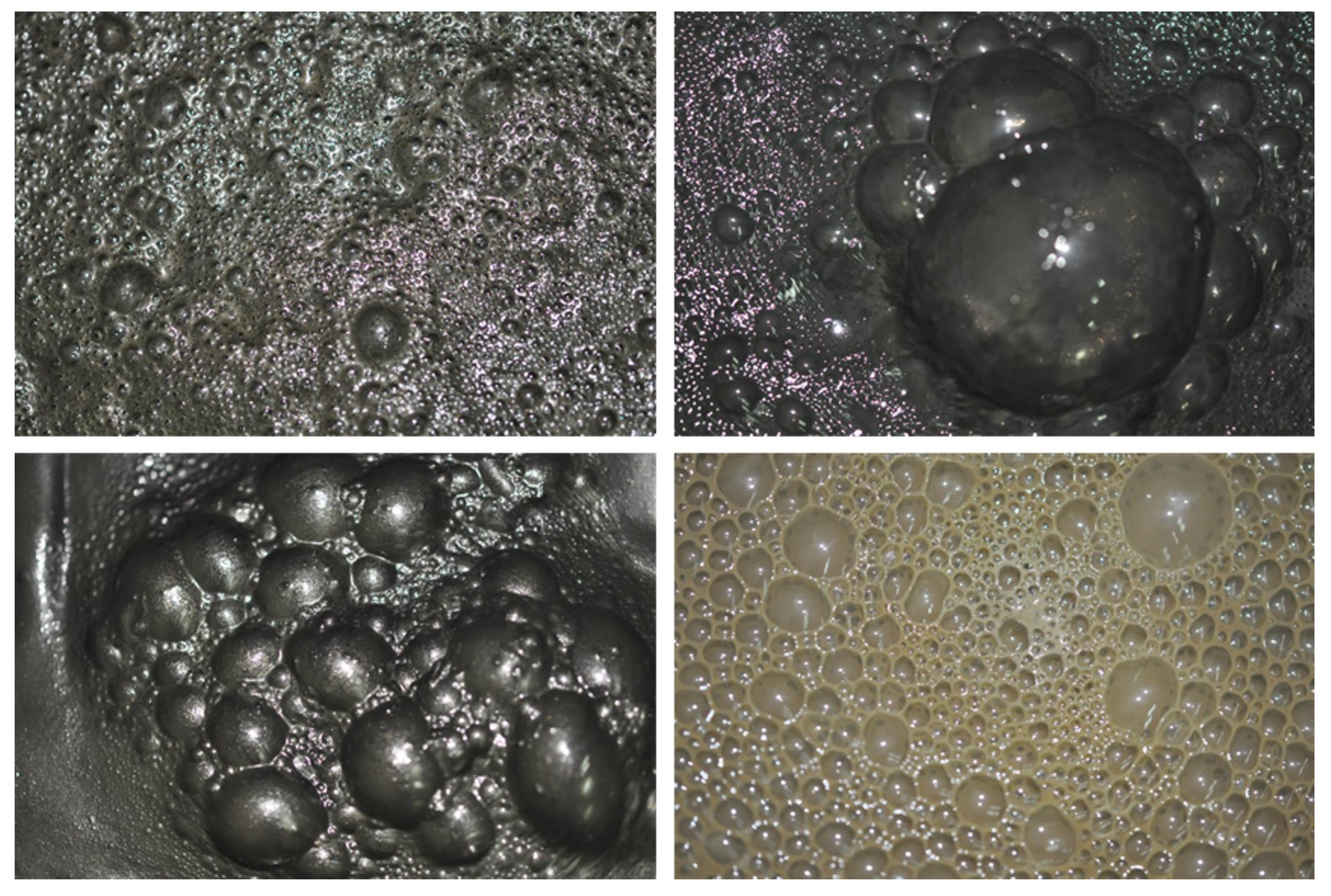
7], in which two databases of froth images were created, on two different setups: (1) in a quasi-2D cell, where the bubbles looked flattened and, (2) in a laboratory column, where the images were taken from the top. In the work by Mesa et al., these databases were obtained from experiments conducted using only a water/frothing agent mixture. Thus, the previous research aimed to classify the froth quality according to the type of frothing agent, without considering variables such as water quality, pH, air injection, and mineralogy, which also influences froth stability. Furthermore, these experiments are barely comparable to industrial froths, which are operationally complex and have a mineral load (
Figure 1). The current study includes a set of different minerals, as well as experiments with variations in water quality, pH, pulp temperature, air injection rate, and reagent dosage in order to create different types of froths; thus, simulating the performance of a froth flotation plant.
This database can be widely used in research targeting visual properties in mineral flotation froth; research in froth stability associated with variables studied such as agent dosage and air flow; research in froth color as a function of the mineral treated, and in studies of bubble morphology and algorithms for estimating bubble size and shape, among others [
8].
2. Data Description
The resultant database, including all the tests performed, contains 2250 images, divided into 45 categories of 50 images each. The database also includes a spreadsheet file named ImagesCatalog.xlsx, which contains the flotation operational conditions under which each category was obtained, and information about the visual properties, which are seen in the images corresponding to each category, including the perceived quality of the froth.
The first sheet of this file contains information associated with the manipulated variables that were controlled during all the tests, including a description of the mix of minerals that were processed, the dosage of frother and collector, the air flow, the type of water, and the flotation time.
The second sheet contains information on the visual characteristics of the bubbles, which can be used to define froth quality. These characteristics are as follows:
Color: This is the dominant color observed in the bubbles, by overlooking the zones where the flash overilluminates the surface. The color is entirely related to the mineral being treated and can be linked to the concentration of mineral present in the bubbles [
9]. The most common colors in the database are black, gray, gold, and brown. A sample of this spectrum is shown in
Figure A1.
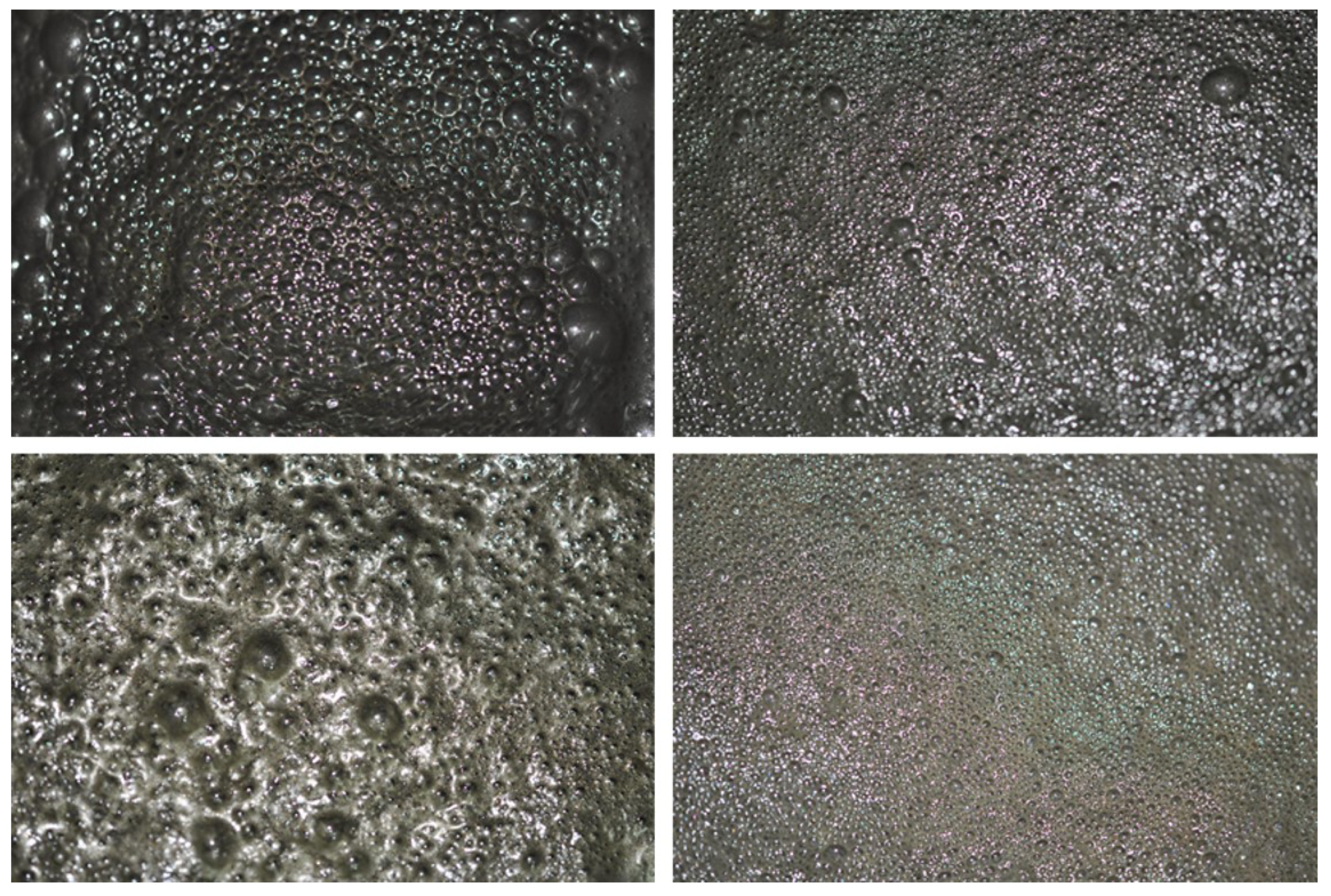
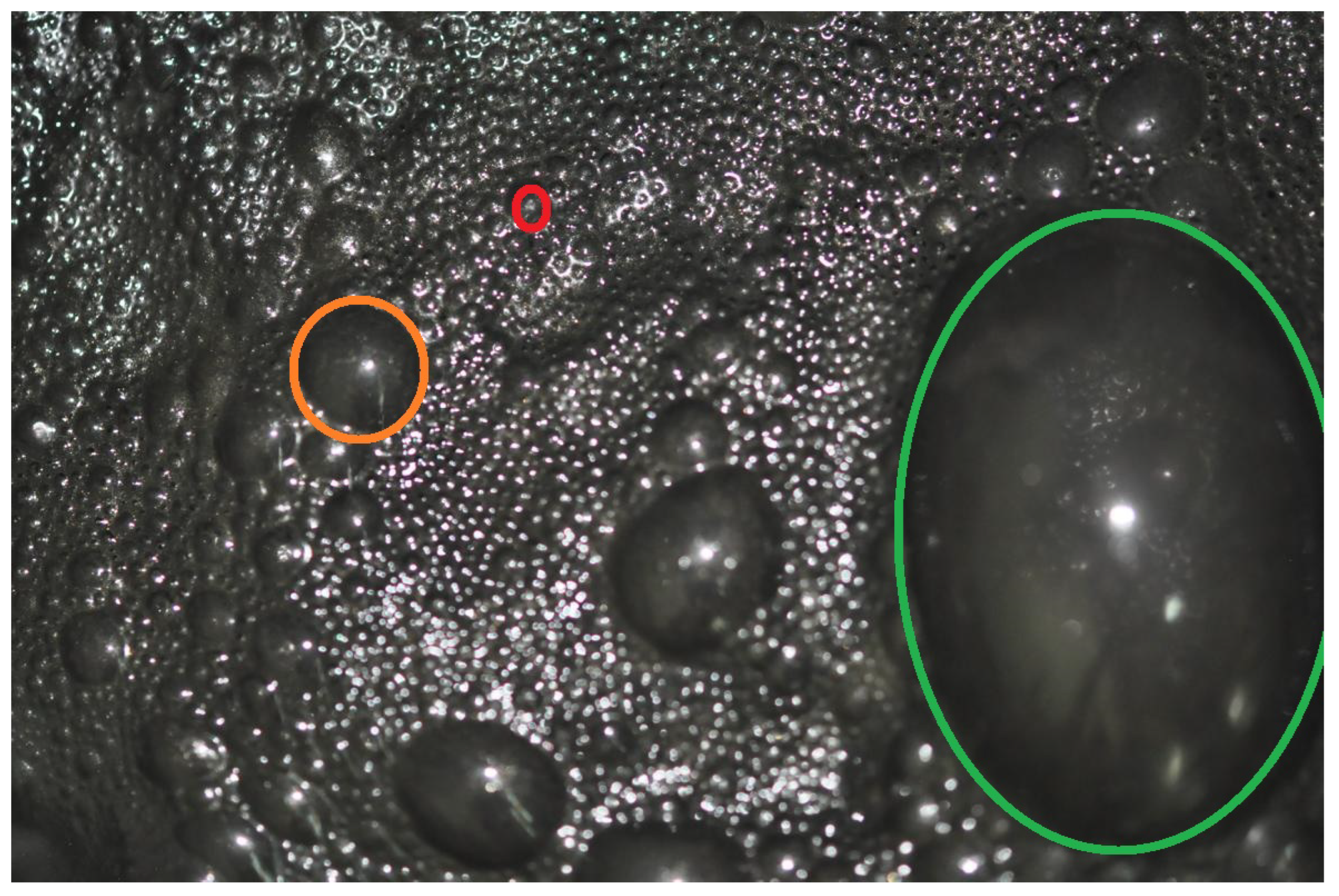
Bubble size: This is the range of sizes observed in the images of each category. This item does not contain information about the actual size of the bubbles; instead, it is an estimation of the size. The options are
big,
medium and
small. Samples of these sizes are shown in
Figure A2.
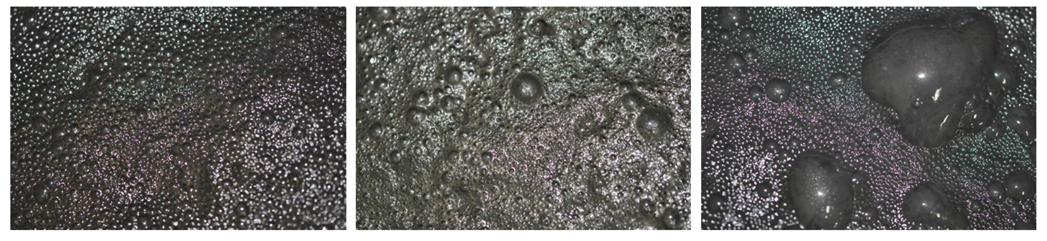
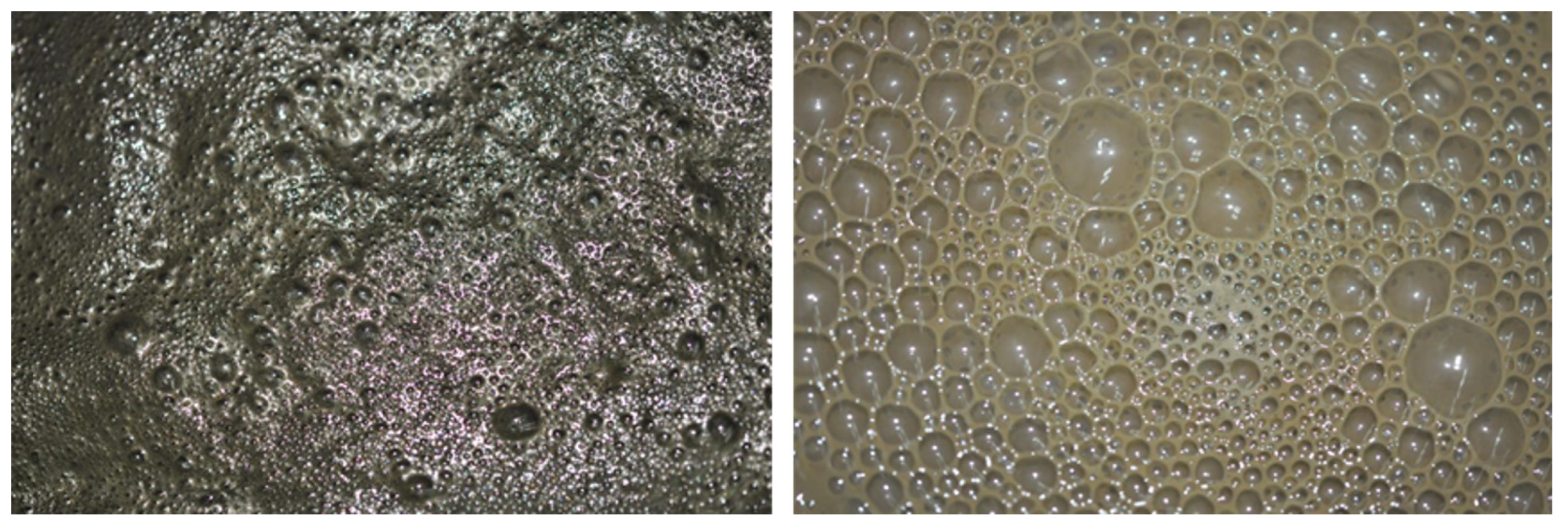
Bubble size distribution: It is the observed bubble size distribution. In other words, it is a characterization of the homogeneity of the sizes. The options are (1)
homogeneous, which means that all bubbles are within the same size range, (2)
pseudo-homogeneous, which means that there are bubbles of different sizes, but there is continuity between the different ranges, and (3)
heterogeneous, which means that there is a disparate size range coexisting on the cell surface. These distributions are shown in
Figure A3.
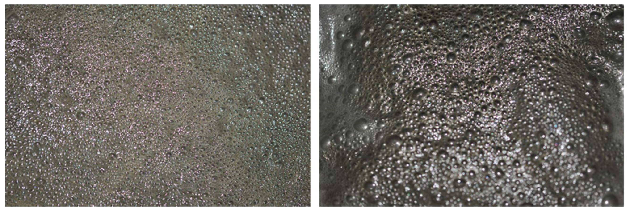
Stability: This is the apparent movement that can be detected in the froth. A froth that shows stillness and an equal height level can be considered a
stable froth. On the other hand, a froth that shows surface undulations and height differences is considered an
unstable froth.
Figure A4 shows the difference between
stable and
unstable froth.
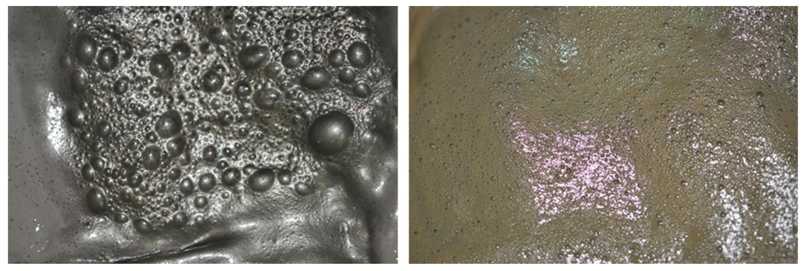
Froth load: This is defined as the presence of particles on the surface of the bubbles. It can be noticed by the translucency of the bubbles. If it is possible to see through the bubbles, it means that the froth has no particles attached to it [
10]. This is usually a sign of underdosing of the collector, or it reveals problems with the chemical conditions inside the equipment.
Figure A5 shows the difference between
loaded and
unloaded froth.
Visible pulp: This is the presence of metallurgical pulp on the cell surface. It may appear on the sides of the froth or between the bubbles. It is usually a sign of low frother dosage or problems with the air distribution within the cell.
Figure A6 shows both cases of pulp on the cell surface.
The last variable reported is froth quality classification. The latter is related to the interpretation of the operation of the flotation cell relative to the appearance observed in the froth. A froth can be assessed as an adequate quality when it presents high ore recovery and low waste recovery. This can be obtained with the correct operation of the equipment and proper management of the chemical conditions. On the other hand, a froth can be assessed as inadequate quality when there are signs that suggest operational problems that may negatively impact recovery.
Even though froth quality identification is a conjunction of all the visual characteristics listed above, there are two parameters that are categorical to determine its quality: if the froth does not present mineral load on the bubbles, and if it presents visible pulp on the surface, it can be immediately categorized as an inadequate froth. These two variables are a visible sign indicating that the flotation phenomenon is not taking place.
In other cases, there might be signs suggesting operational problems, but they are not categorical to determine if the quality of the froth is
adequate or
inadequeate. For example, a shallow unstable froth is likely formed because the bubble structure is not strong enough, a sign of lack of frother [
11]. Additionally, large-sized bubbles, or heterogeneous bubbles depending on their sizes, are a sign of problems with air distribution within the equipment. Moreover, different sizes may imply different rising velocities, leading to bubble collisions and coalescence, a phenomenon that is unfavorable [
12]. Thus, since in some cases it is not entirely clear whether a froth is of
adequate quality or not, these ambiguous-looking images were classified as
indeterminate quality.
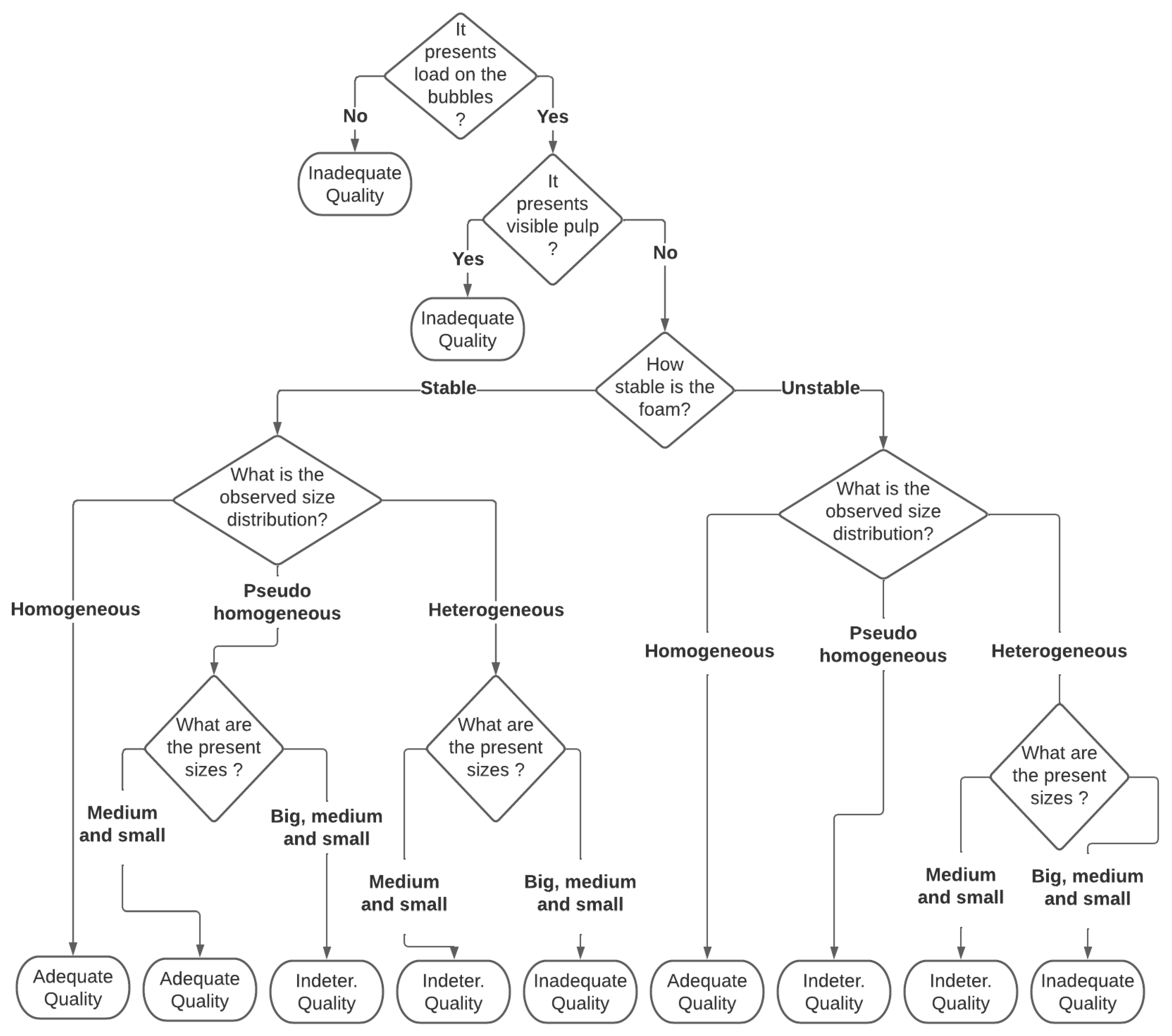
To generalize the definition of froth quality to different situations, a series of rules were established in the form of a decision tree (
Figure 2), which depends on the visual properties detected in the froth. Thus, depending on the visual characterization of the froth at a given time, the froth quality can be expressed as
adequate,
inadequate, or
indeterminate.
Finally, since the attributes possessed by the 50 images belonging to a category are the same, the structure at the attribute level is described on a category basis. The list of attributes that characterize each category is shown in
Table 1, which has the same naming nomenclature as the
ImagesCatalog.xlsx file associated with the database.
3. Methods
In this work, the Magotteaux flotation cell was used; this equipment can operate up to 5 L of pulp and has the advantage of being uncovered at the top. This arrangement allows obtaining photographs directly from the froth zone. It also permits to have control of the air flow and the revolutions of the rotor. This process was constantly monitored with external instruments, such as a pH meter and a flow sensor.
The first step was to elaborate a flotation protocol that was used throughout all tests. Then, the conditions were established, aiming to closely mimic the conditions in a real froth flotation plant. Finally, the camera settings were considered in order to obtain highquality images.
3.1. Experimental Setup and Flotation Protocol
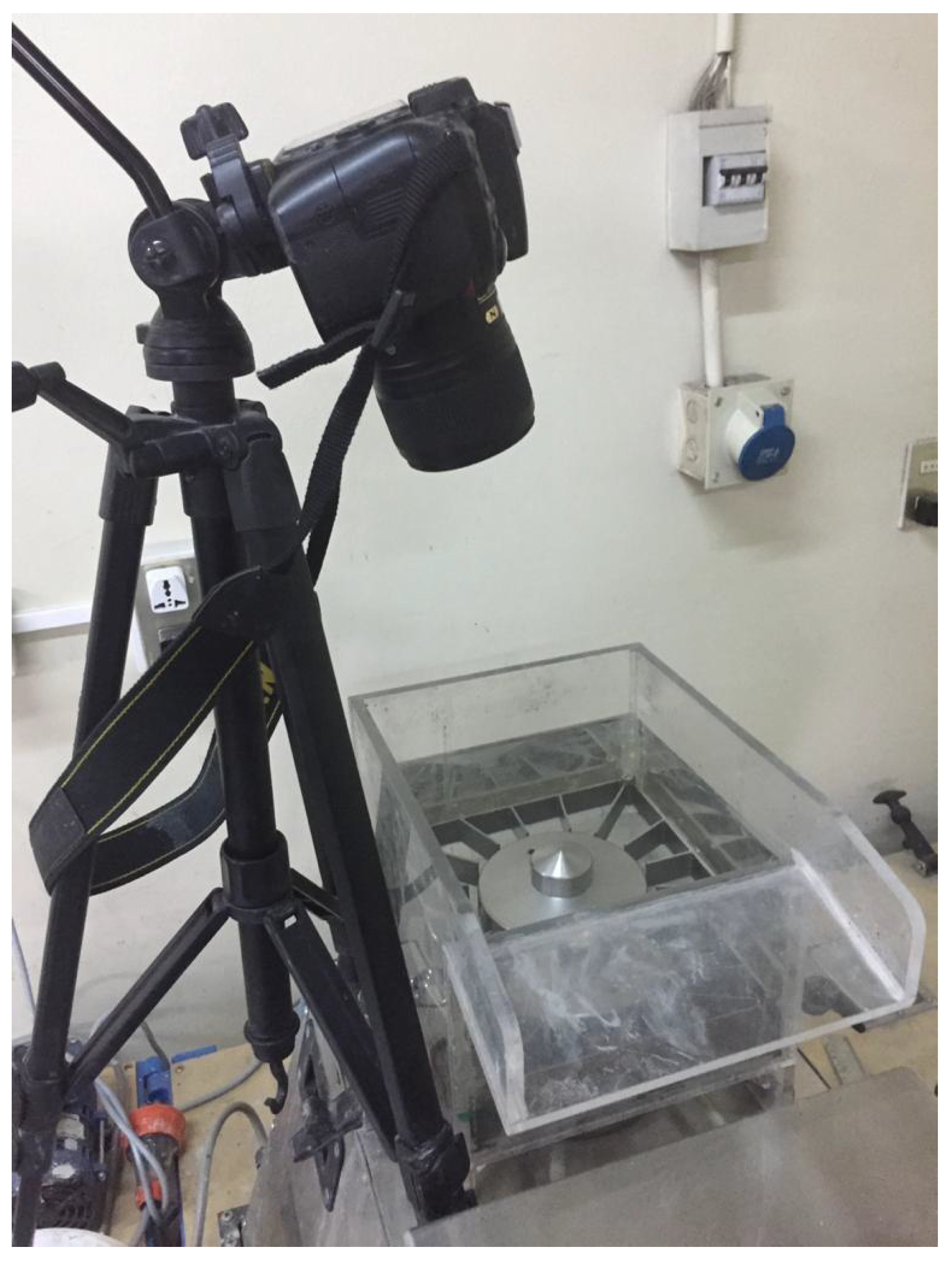
The experimental setup assembled for the laboratory tests is shown in
Figure 3. The camera was situated at the side of the Magotteaux cell, at a distance of 25 cm approximately from the froth zone, and mounted on a tripod. The camera was manipulated to point towards the center of the cell, leaving the edges and the background out of the image. No zoom was applied.
A flotation protocol was designed to standardize all the tests. This protocol had the following steps:
Pulp preparation: The specific mineral and water mixture were prepared proportionally so that a percentage of solids in weight (cp) remained between 30% and 35% [
13]. To achieve the cp condition, considering the volume of the cell, a mass of 1.800 g of mineral, as well as a volume of 4.200 mL of water, were required.
Agent preparation: The dosage of collector and frother were prepared according to the test. A precision scale was used for this purpose.
Conditioning stages: Two stages were required to prepare the mineral for the flotation process. In the first stage, the pulp was stirred at a speed between 800 and 900 RPM, with an air flow of 18 L/s, without the reagents. In the second stage, the air flow was turned off and the reagents were added, allowing the collector’s adsorption [
14]. Each stage lasted approximately 10 min.
pH adjustment: During the conditioning stages, a pH meter was installed inside the cell. Lime was added until reaching a pH between 9 and 10. This parameter was controlled during the entire test, adding extra lime solution when the pH fell below 9.
Flotation stage: The air flow was turned on, and the flotation started. The stirring speed increased until reaching a value between 1100 and 1200 RPM. The concentrate produced was collected in a tray while the camera was obtaining photos from the froth zone.
3.2. Variation of Experimental Conditions
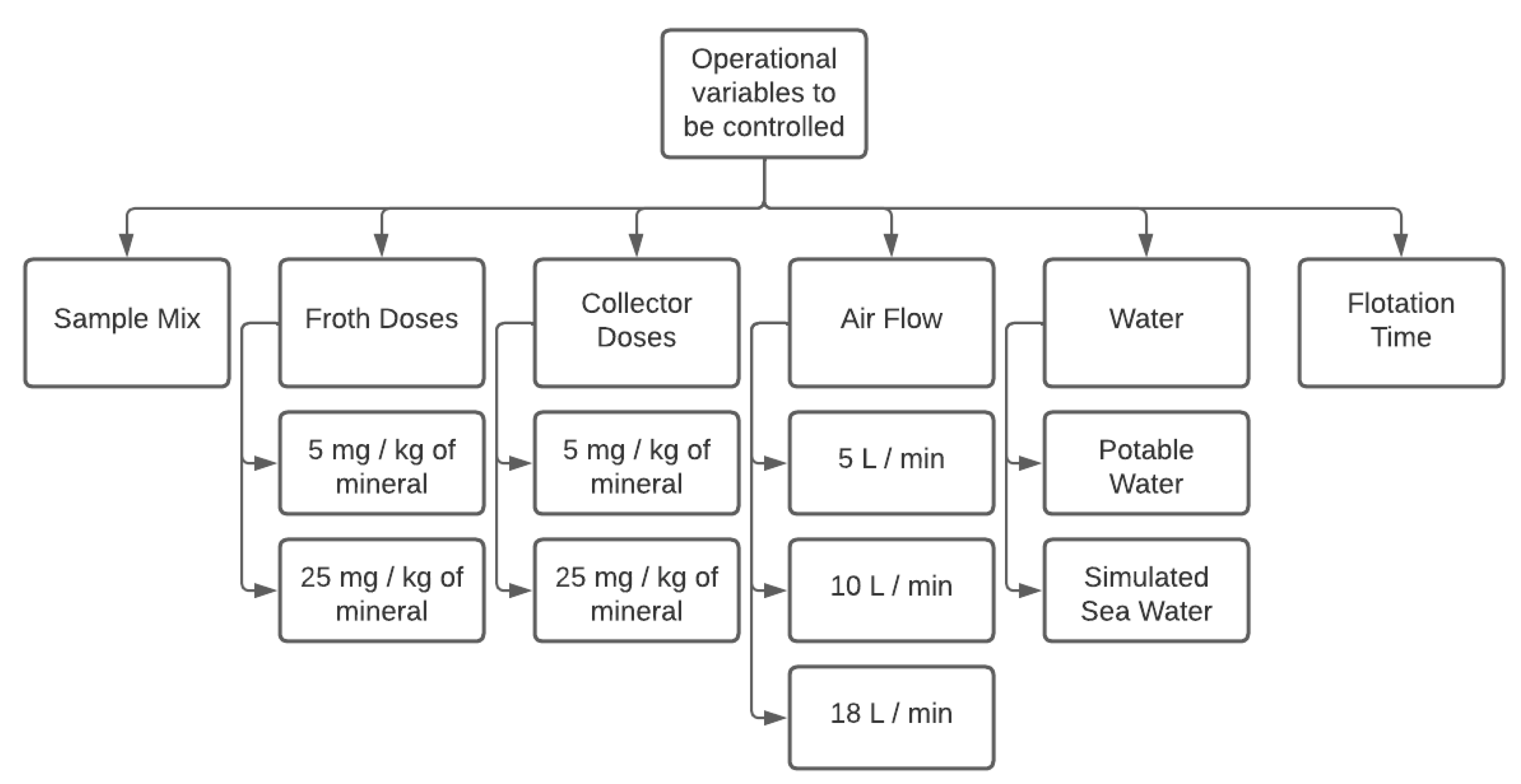
As previously mentioned, this study was conducted to assess different variables involved in the flotation process. This section explains the information related to operational variables and how they were controlled while performing the tests. A general scheme of these variables is shown in
Figure 4.
Mineralogy: The work was performed with different mineral samples extracted from a variety of ore deposits. All samples were previously milled, achieving 100% under 200 (−75 um). Each test was performed with a different sample or a blend of two or more samples. The compositions of each individual sample were as follows:
- −
Sample 1: Mineral obtained from a sulfide copper deposit. It contained chalcopyrite, albite, plagioclase, quartz, calcite, muscovite, chlorite, epidote, and a variety of clays, with traces of other minerals. The predominant colors were gray and yellow.
- −
Sample 2: Mineral obtained from a sulfide copper deposit; it also contained organic material. The specific composition was unknown. The predominant color was black.
- −
Sample 3: Mineral obtained from the superficial area of a sulfide copper deposit, meaning that the sample was mainly composed of oxidized minerals. The specific composition was unknown. The predominant colors were yellow and orange.
- −
Sample 4: Confirmedonly by a specific clay, kaolinite. Judging by the natural size of the particles that met the required size, this sample did not need grinding. The predominant color was white.
Agent dosage: Two different reagents were used. The main collector used was xanthate and it was applied in two dosages: 5 mg per kilogram of mineral (low dosage) and 25 mg per kilogram of mineral (normal dosage) [
15]. The frother was Aerofroth 76E, and was applied in the same dosage as the collector, meaning 5 mg per kilogram of mineral at a low dosage, and 25 mg per kilogram of mineral at a normal dosage [
16]. In some cases within the first conditioning stage, and before adding the frother and the collector, a layer of froth appeared. These cases were also included in the database.
Air flow: It is defined as a variable named Jg, which is a normalization of the flow by the area of the cell, being useful to compare cells of different sizes. Considering the standard values for Jg and the area of the Magotteaux cell (
Table 2), the values used were from [
17].
Exceptionally, there was a case where even with no airflow injected into the equipment, a layer of froth was formed on the top of the cell, probably from the air trapped between the solid particles. This case was also included in the database.
Water: Two different sources of water were used in the study: (1) drinking water and (2) simulated seawater. The latter was made from distilled water mixed with a combination of salts and minerals to mimic seawater [
18]. Water was added to the mineral in order to form the pulp phase.
Flotation time: The flotation time was measured and controlled as a variable. Some images in the database were obtained at the beginning of the test; meanwhile, others were obtained after a flotation time ranging between 5 and 10 min.
There were two operational variables that were additionally controlled during all the tests: pH and temperature. The control of the pH was carried out by adding lime to the pulp while it was checked using a pH meter. Lime was added until the pulp reached a pH between 9 and 10, which is the standard pH value for copper froth flotation [
19]. Meanwhile, temperature control was evaluated using a thermometer inside the cell. The temperature was maintained lower than 40 °C/104 °F in order to prevent the oxidation of the mineral inside the equipment, which may reduce the recovery of the mineral of interest. This was achieved by controlling the revolutions of the motor, the main heat source of the process. Importantly, a number of categories were obtained before this protocol was established; thus, information about the working conditions was missing in some cases. These preliminary tests were performed at the beginning of the study, in order to learn and practice with the equipment. These cases were included since they had particular froth characteristics that were absent in the remaining images.
3.3. Camera
The images were obtained using a professional photography camera, Nikon model D90 [
20]. The technical specifications were:
Micro-Nikkor AF-S 60 mm f/2.8G ED camera lens.
The distance of focus was adjusted at the beginning of the test using an approximate value of 25 cm. Afterwards, it was automatically adjusted for each photograph. This parameter needed periodic adjustment because of the froth constant movement, which caused the camera to lose the focus.
The flash incorporated in the camera was the lightning source. It had a synchronization speed of 0.005 s.
The regular mode for taking a photograph was manual, with the flash turned on.
3.4. Image Selection and Processing
In each category, the initial number of images ranged between 60 and 80. Then, the 50 best images were selected on each category in order to create a balanced database. The main flaws that caused an image to be discarded were excess of illumination, blurred images, failure at positioning the background, and excess of movement when obtaining the image. Each of the images obtained had dimensions of 4288 × 2848 pixels, and an approximate size of 3.4 megabytes. However, this size was considered excessively large to solve the algorithms. To correct this, images were reduced using an resize algorithm included in Python, which considered keeping the proportion between axes. Each of the final images had a dimension of 1180 × 784 pixels, with a size of 95 kilobytes.
3.5. Technical Validation
To demonstrate the reliability and consistency of the different types of information presented, two classification algorithms were applied to the images in order to predict the quality of the foam. According to their definition (
Figure 2), the froth quality is a function of different visual characteristics perceived in the froth image, thus proving an interesting case study to test the image–froth quality relationship with data-driven mathematical models.
The following two methods were used to classify foam images according to their perceived quality: a comparison method based on the calculation of a compact variographic map combined with K-nearest neighbors classifier [
21], and a method based on the use of convolutional neural networks [
22]. For this technical validation it was decided that only the images characterized with
adequate or
inadequate froth quality were classified, due to the appreciable differences behind these labels.
The results obtained with both classification algorithms in the different tests performed gave results greater than 90% of accuracy rate in all the cases. The details of the experiments performed can be found in the
Appendix B, together with the results obtained in each situation.
Importantly, the results obtained with the Magotteaux cell are not directly scalable with the results that could potentially be obtained when using this method in an industrial flotation cell, given the differences both in size and in mode of operation. However, with the correct methodology for capturing the images, and the correct characterization process, the results obtained in an industrial tank could be as good as those obtained in the Magotteaux cell.
4. Conclusions
This paper presents a comprehensive database of froth images of flotation experiments performed in a five-liter Magotteaux cell. This cell has the advantage of a fully immersed impeller which allows taking pictures of the complete surface of the cell. Forty-five different flotation conditions, which changed in reagent dosage, ore type, air flow, type of water, and flotation time were tested. In each condition, fifty images were captured and classified as adequate, inadequate, or indeterminate by the operator. Then, the images were also classified by two different algorithms that assigned a class. The algorithm-classification method reached a 90% accuracy in comparison with the manual classification. Hence, the data provided in this paper can have multiple uses in research targeting visual properties in mineral flotation froth and image classification.
5. User Notes
In the database, images are sorted by numbers from 1 to 2250. The spreadsheet file ImagesCatalog.xlsx, presented with the image dataset, points out the 50 images assigned to each category. This document also contains the experimental conditions that generate each category and the visual characteristics observed, including the perceived quality of the froth.
Author Contributions
Conceptualization, C.Y., W.K. and A.E.; methodology, C.Y., W.K. and G.D.; software, C.Y.; validation, C.Y. and G.D.; formal analysis, C.Y., G.D. and A.E.; investigation, C.Y.; resources, W.K., P.L.-M. and A.E.; data curation, C.Y. and G.D.; writing—original draft preparation, C.Y.; writing—review and editing, C.Y., G.D., P.L.-M. and A.E.; visualization, C.Y.; supervision, W.K., G.D., P.L.-M. and A.E.; project administration, W.K. and P.L.-M.; funding acquisition, W.K. and P.L.-M. All authors have read and agreed to the published version of the manuscript.
Funding
This research was funded by the Agencia Nacional de Investigación y Desarrollo (Ministerio de Ciencia, Tecnología, Conocimiento, e Innovación, Chile) grant number PIA AFB180004.
Institutional Review Board Statement
Not applicable.
Informed Consent Statement
Not applicable.
Data Availability Statement
The data presented in this study are openly available in FigShare at doi.org/10.6084/m9.figshare.21437292, accessed on 19 January 2023.
Acknowledgments
The authors would like to thank Paula Díaz for her technical support in drafting and proofreading the article.
Conflicts of Interest
The authors declare no conflict of interest.
Appendix A. Demonstrative Examples of Froth Images
Figure A1.
Color differences between categories.
Figure A1.
Color differences between categories.
Figure A2.
Characterization and comparison of bubble sizes. In the image, a big bubble is labeled with a green circle, a medium-sized bubble with an orange circle, and a small-sized bubble with a red circle.
Figure A2.
Characterization and comparison of bubble sizes. In the image, a big bubble is labeled with a green circle, a medium-sized bubble with an orange circle, and a small-sized bubble with a red circle.
Figure A3.
Comparison between sizes distributions in froths. The (left image) has a homogeneous size distribution, the (center image) has a pseudo-homogeneous size distribution, and the (right image) has a heterogeneous size distribution.
Figure A3.
Comparison between sizes distributions in froths. The (left image) has a homogeneous size distribution, the (center image) has a pseudo-homogeneous size distribution, and the (right image) has a heterogeneous size distribution.
Figure A4.
Differences in froth stability. The (left) image shows a case with a stable froth and the (right image) shows a case with an unstable froth.
Figure A4.
Differences in froth stability. The (left) image shows a case with a stable froth and the (right image) shows a case with an unstable froth.
Figure A5.
Difference between a loaded froth (left image) and an unloaded froth (right image).
Figure A5.
Difference between a loaded froth (left image) and an unloaded froth (right image).
Figure A6.
Visible pulp on the sides of the froth (left image) and between the bubbles (right image).
Figure A6.
Visible pulp on the sides of the froth (left image) and between the bubbles (right image).
Appendix B. Classification Experiments
In these experiments, the aim is to predict the froth quality of the different images analyzed, considering only the cases
adequate and
inadequate of the target variable. To this end, two classification algorithms were used: a method based on compact variogram characterization [
7,
21] and a method based on convolutional neural networks [
22,
23].
Since there are more categories of images that have adequate quality than inadequate quality, three cases were generated for analysis that have data of both qualities in the same proportion. Each of these three cases were originated in the following way:
From all images of adequate quality, 450 images were selected for training and 200 images for test. This selection in each case was random and without repetition.
From all images of inadequate quality, 450 images were selected for training and 200 images for test. This selection in each case was random and without repetition.
In this manner, each case was defined with a total of 900 training images and a total of 400 test images. In each case, the set of training images were used to adjust the parameters of each model, while the set of test images were used to evaluate the prediction obtained in comparison with the previously defined froth quality. This comparison was made using the accuracy rate, i.e., considering the proportion of images in the test set in which the prediction was correct for each classification method.
With the compact variogram method, a radius of 45 pixels and a total of 61 points to be calculated were used. Previous tests showed that the number of neighbors did not generate a considerable difference in the prediction of the method, so only the nearest neighbor was used to assign the corresponding quality. The method was repeated on three occasions, each one randomly changing the composition of the training dataset and the validation dataset.
Table A1 shows the results obtained for the accuracy with this method in each repetition of the test.
Table A1.
Accuracy rate (%) with compact variographic map method.
Table A1.
Accuracy rate (%) with compact variographic map method.
| N° Case | Accuracy Rate (%) |
|---|
| 1 | 92.25% |
| 2 | 94.75% |
| 3 | 92% |
On the other hand, using the convolutional neural network method, a scheme with two convolutional layers and two dense layers of 60 neurons each was considered. The model was trained with a total of 20 epochs. This method was also repeated on three occasions, changing both datasets, training and validation.
Table A2 shows the results obtained for the accuracy with this method.
Table A2.
Accuracy rate (%) with convolutional neural network.
Table A2.
Accuracy rate (%) with convolutional neural network.
| N° Case | Accuracy Rate (%) |
|---|
| 1 | 93% |
| 2 | 93.75% |
| 3 | 95% |
References
- Wills, B. Chapter 12—Froth Flotation. In Mineral Processing Technology, 4th ed.; Elsevier: Amsterdam, The Netherlands, 1988; pp. 457–595. [Google Scholar]
- Schlesinger, M.; King, M.; Sole, K.; Davenport, W. Chapter 1—Overview. In Extractive Metallurgy of Copper, 5th ed.; Elsevier: Amsterdam, The Netherlands, 2011; pp. 1–12. [Google Scholar]
- Saavedra Moreno, Y.; Bournival, G.; Ata, S. Foam stability of flotation frothers under dynamic and static conditions. Sep. Purif. Technol. 2021, 274, 117822. [Google Scholar] [CrossRef]
- Jahedsaravani, A.; Massinaei, M.; Marhaban, M. An image segmentation algorithm for measurement of flotation froth bubble size distributions. Measurement 2017, 111, 29–37. [Google Scholar] [CrossRef]
- Yantén, C. Desarrollo de Herramienta de Caracterización de Espumas de Flotación a Partir de Análisis Textural de Imágenes; Memoria de título. Ingeniería Civil de Minas, Universidad de Chile: Santiago, Chile, 2020. [Google Scholar]
- Magotteaux Float Cell™. 2022. Available online: https://www.magotteaux.com/products/laboratory-flotation-magotteaux-float-celltm (accessed on 19 January 2023).
- Mesa, D.; Kracht, W.; Díaz, G. Textural image classification of foams based on variographic analysis. Miner. Eng. 2016, 98, 52–59. [Google Scholar] [CrossRef]
- Wang, X.; Zhou, J.; Wang, Q.; Liu, D.; Lian, J. An unsupervised method for extracting semantic features of flotation froth images. Miner. Eng. 2022, 176, 107344. [Google Scholar] [CrossRef]
- Bonifazi, G.; Serranti, S.; Volpe, F.; Zuco, R. Characterisation of flotation froth colour and structure by machine vision. Comput. Geosci. 2001, 27, 1111–1117. [Google Scholar] [CrossRef]
- Ostadrahimi, M.; Gharibi, K.; Dehghani, A.; Farrokhpay, S. Estimating Bubble Loading in Industrial Flotation Cells. Minerals 2019, 9, 222. [Google Scholar] [CrossRef] [Green Version]
- Gupta, A.; Banerjee, P.; Mishra, A. Effect of Frothers on Foamability, Foam Stability, and Bubble Size. Coal Prep. 2007, 27, 107–125. [Google Scholar] [CrossRef]
- Wang, H.; Yang, W.; Yan, X.; Wang, L.; Wang, Y.; Zhang, H. Regulation of bubble size in flotation: A review. J. Environ. Chem. Eng. 2020, 8, 104070. [Google Scholar] [CrossRef]
- Wiese, J.; Harris, P.; Bradshaw, D. The effect of the reagent suite on froth stability in laboratory scale batch flotation tests. Miner. Eng. 2011, 24, 995–1003. [Google Scholar] [CrossRef]
- Chandra, A.; Gerson, A. A review of the fundamental studies of the copper activation mechanisms for selective flotation of the sulfide minerals, sphalerite and pyrite. Adv. Colloid Interface Sci. 2009, 145, 97–110. [Google Scholar] [CrossRef] [PubMed]
- Azizi, A. A study on the modified flotation parameters and selectivity index in copper flotation. Part. Sci. Technol. 2017, 35, 38–44. [Google Scholar] [CrossRef]
- Mpongo, M. Effect of collector, frother and depressant addition on the copper recovery and concentrate grade of the nchanga underground scavenger circuit of Konkola copper mine-Zambia. Afr. J. Sci. Technol. 2010, 7, 8–11. [Google Scholar] [CrossRef] [Green Version]
- Schwarz, S.; Alexander, D. Gas dispersion measurements in industrial flotation cells. Miner. Eng. 2006, 19, 554–560. [Google Scholar] [CrossRef]
- Kester, D.; Duedall, I.; Connors, D.; Pytkowicz, R. Preparation of Artificial Seawater1. Limnol. Oceanogr. 1967, 12, 176–179. [Google Scholar] [CrossRef]
- Castro, S. Challenges in flotation of Cu-Mo sulfide ores in sea water. In Water in Mineral Processing; Society for Mining, Metallurgy & Exploration (SME): Littleton, CO, USA, 2012; pp. 29–40. [Google Scholar]
- Hilz, C. The Camera. In Nikon D90; Elsevier: Amsterdam, The Netherlands, 2009; pp. 3–150. [Google Scholar]
- Diaz, G.; Ortiz, J.; Silva, J.; Lobos, R.; Egaña, A. Variogram-based descriptors for comparison and classification of rock texture images. Math. Geosci. 2020, 52, 451–476. [Google Scholar] [CrossRef]
- Géron, A. Chapter 14—Deep Computer Vision Using Convolutional Neural Networks. In Hands-On Machine Learning with Scikit-Learn, Keras, and TensorFlow, 3rd ed.; O’Reilly Media: Sebastopol, CA, USA, 2022. [Google Scholar]
- Zarie, M.; Jahedsaravani, A.; Massinaei, M. Flotation froth image classification using convolutional neural networks. Miner. Eng. 2020, 155, 106443. [Google Scholar] [CrossRef]
| Disclaimer/Publisher’s Note: The statements, opinions and data contained in all publications are solely those of the individual author(s) and contributor(s) and not of MDPI and/or the editor(s). MDPI and/or the editor(s) disclaim responsibility for any injury to people or property resulting from any ideas, methods, instructions or products referred to in the content. |
© 2023 by the authors. Licensee MDPI, Basel, Switzerland. This article is an open access article distributed under the terms and conditions of the Creative Commons Attribution (CC BY) license (https://creativecommons.org/licenses/by/4.0/).


 ,
, 


