
Pre-Planning the Surgical Target for Optimal Implant Positioning in Robotic-Assisted Total Knee Arthroplasty

 ,
,  , ,
, ,
Abstract
:1. Introduction
2. Materials and Methods

3. Results
4. Discussion
Author Contributions
Funding
Institutional Review Board Statement
Informed Consent Statement
Data Availability Statement
Acknowledgments
Conflicts of Interest
References
- Sikorski, J.M. Alignment in total knee replacement. J. Bone Jt. Surg. Br. 2008, 90, 1121–1127. [Google Scholar] [CrossRef] [PubMed]
- Thompson, J.A.; Hast, M.W.; Granger, J.F.; Piazza, S.J.; Siston, R.A. Biomechanical effects of total knee arthroplasty component malrotation: A computational simulation. J. Orthop. Res. 2011, 29, 969–975. [Google Scholar] [CrossRef] [PubMed]
- Fehring, T.K. Rotational malalignment of the femoral component in total knee arthroplasty. Clin. Orthop. Relat. Res. 2000, 380, 72–79. [Google Scholar] [CrossRef] [PubMed]
- Kuriyama, S.; Ishikawa, M.; Furu, M.; Ito, H.; Matsuda, S. Malrotated tibial component increases medial collateral ligament tension in total knee arthroplasty. J. Orthop. Res. 2014, 32, 1658–1666. [Google Scholar] [CrossRef] [PubMed]
- Steinbrück, A.; Fottner, A.; Schröder, C.; Woiczinski, M.; Schmitt-Sody, M.; Müller, T.; Müller, P.E.; Jansson, V. Influence of mediolateral tibial baseplate position in TKA on knee kinematics and retropatellar pressure. Knee Surg. Sports Traumatol. Arthrosc. 2017, 25, 2602–2608. [Google Scholar] [CrossRef]
- Kayani, B.; Konan, S.; Ayuob, A.; Onochie, E.; Al-Jabri, T.; Haddad, F.S. Robotic technology in total knee arthroplasty: A systematic review. EFORT Open Rev. 2019, 4, 611–617. [Google Scholar] [CrossRef]
- Song, E.K.; Seon, J.K.; Yim, J.H.; Netravali, N.A.; Bargar, W.L. Robotic-assisted TKA reduces postoperative alignment outliers and improves gap balance compared to conventional TKA knee. Clin. Orthop. Relat. Res. 2013, 471, 118–126. [Google Scholar] [CrossRef]
- Kayani, B.; Konan, S.; Pietrzak, J.R.T.; Haddad, F.S. Iatrogenic bone and soft tissue trauma in robotic-arm assisted total knee arthroplasty compared with conventional jig-based total knee arthroplasty: A prospective cohort study and validation of a new classification system. J. Arthroplast. 2018, 33, 2496–2501. [Google Scholar] [CrossRef]
- Khlopas, A.; Chughtai, M.; Hampp, E.L.; Scholl, L.Y.; Prieto, M.; Chang, T.-C.; Abbas, A.; Bhowmik-Stoker, M.; Otto, J.; Jacofsky, D.J.; et al. Robotic-arm assisted total knee arthroplasty demonstrated soft tissue protection. Surg. Technol. Int. 2017, 30, 441–446. [Google Scholar] [PubMed]
- Hampp, E.L.; Chughtai, M.; Scholl, L.Y.; Sodhi, N.; Bhowmik-Stoker, M.; Jacofsky, D.J.; Mont, M.A. Robotic-arm assisted total knee arthroplasty demonstrated greater accuracy and precision to plan compared with manual techniques. J. Knee Surg. 2019, 32, 239–250. [Google Scholar] [CrossRef]
- Sires, J.D.; Craik, J.D.; Wilson, C.J. Accuracy of bone resection in MAKO total knee robotic-assisted surgery. J. Knee Surg. 2021, 34, 745–748. [Google Scholar] [CrossRef] [PubMed]
- Ollivier, M.; Parratte, S.; Lino, L.; Flecher, X.; Pesenti, S.; Argenson, J.N. No benefit of computer-assisted TKA: 10-year results of a prospective randomized study. Clin. Orthop. Relat. Res. 2018, 476, 126–134. [Google Scholar] [CrossRef] [PubMed]
- Cherian, J.J.; Kapadia, B.H.; Banerjee, S.; Jauregui, J.J.; Issa, K.; Mont, M.A. Mechanical, anatomical, and kinematic axis in TKA: Concepts and practical applications. Curr. Rev. Musculoskelet. Med. 2014, 7, 89–95. [Google Scholar] [CrossRef] [PubMed]
- Berend, M.E.; Ritter, M.A.; Meding, J.B.; Faris, P.M.; Keating, E.M.; Redelman, R.; Faris, G.W.; Davis, K.E. Tibial component failure mechanisms in total knee arthroplasty. Clin. Orthop. Relat. Res. 2004, 428, 26–34. [Google Scholar] [CrossRef]
- Bellemans, J.; Colyn, W.; Vandenneucker, H.; Victor, J. The Chitranjan Ranawat Award: Is neutral mechanical alignment normal for all patients?: The concept of constitutional varus. Clin. Orthop. Relat. Res. 2012, 470, 45–53. [Google Scholar] [CrossRef]
- Rivière, C.; Villet, L.; Jeremic, D.; Vendittoli, P.A. What you need to know about kinematic alignment for total knee arthroplasty. Orthop. Traumatol. Surg. Res. 2021, 107, 4–6. [Google Scholar] [CrossRef]
- Shatrov, J.; Batailler, C.; Sappey-Marinier, E.; Gunst, S.; Servien, E.; Lustig, S. Kinematic alignment fails to achieve balancing in 50% of varus knees and resects more bone compared to functional alignment. Knee Surg. Sports Traumatol. Arthrosc. 2022, 30, 2991–2999. [Google Scholar] [CrossRef]
- Lee, G.C.; Wakelin, E.; Plaskos, C. What is the alignment and balance of a total knee arthroplasty performed using a calipered kinematic alignment technique? J. Arthroplast. 2022, 37, 176–181. [Google Scholar] [CrossRef]
- Chang, J.S.; Kayani, B.; Haddad, F.S.; Wallace, C. Functional alignment achieves soft-tissue balance in total knee arthroplasty as measured with quantitative sensor-guided technology. Bone Jt. J. 2021, 103-B, 507–514. [Google Scholar] [CrossRef]
- Clark, G.; Steer, R.; Wood, D. Functional alignment achieves a more balanced total knee arthroplasty than either mechanical alignment or kinematic alignment prior to soft tissue releases. Knee Surg. Sports Traumatol. Arthrosc. 2022, 31, 1420–1426. [Google Scholar] [CrossRef]
- Tzanetis, P.; De Souza, K.; Robertson, S.; Fluit, R.; Koopman, B.; Verdonschot, N. Numerical study of osteophyte effects on pre-operative knee functionality in patients undergoing robotic-assisted total knee arthroplasty. J. Orthop. Res. 2022; submitted. [Google Scholar]
- Marra, M.A.; Vanheule, V.; Fluit, R.; Koopman, B.H.F.J.M.; Rasmussen, J.; Verdonschot, N.; Andersen, M.S. A subject-specific musculoskeletal modeling framework to predict in vivo mechanics of total knee arthroplasty. J. Biomech. Eng. 2015, 137, 020904. [Google Scholar] [CrossRef]
- Oussedik, S.; Scholes, C.; Ferguson, D.; Roe, J.; Parker, D. Is femoral component rotation in a TKA reliably guided by the functional flexion axis? Clin. Orthop. Relat. Res. 2012, 470, 3227–3232. [Google Scholar] [CrossRef]
- Bowes, M.A.; Kacena, K.; Alabas, O.A.; Brett, A.D.; Dube, B.; Bodick, N.; Conaghan, P.G. Machine-learning, MRI bone shape and important clinical outcomes in osteoarthritis: Data from the Osteoarthritis Initiative. Ann. Rheum. Dis. 2021, 80, 502–508. [Google Scholar] [CrossRef]
- Motesharei, A.; Batailler, C.; De Massari, D.; Vincent, G.; Chen, A.F.; Lustig, S.; Batailler, C. Predicting robotic-assisted total knee arthroplasty operating time: Benefits of machine-learning and 3D patient-specific data. Bone Jt. Open 2022, 3, 383–389. [Google Scholar] [CrossRef]
- Brett, A.; Bowes, M.A.; Conaghan, P.G. Comparison of 3D quantitative osteoarthritis imaging biomarkers from paired CT and MR images: Data from the IMI-APPROACH study. BMC Musculoskelet. Disord. 2023, 24, 76. [Google Scholar] [CrossRef]
- Carbone, V.; Fluit, R.; Pellikaan, P.; van der Krogt, M.M.; Janssen, D.; Damsgaard, M.; Vigneron, L.; Feilkas, T.; Koopman, H.F.J.M.; Verdonschot, N. TLEM 2.0—A comprehensive musculoskeletal geometry dataset for subject-specific modeling of lower extremity. J. Biomech. 2015, 48, 734–741. [Google Scholar] [CrossRef]
- Hunter, D.J.; Bowes, M.A.; Eaton, C.B.; Holmes, A.P.; Mann, H.; Kwoh, C.K.; Maciewicz, R.A.; Samuels, J.; Waterton, J.C. Can cartilage loss be detected in knee osteoarthritis (OA) patients with 3–6 months’ observation using advanced image analysis of 3T MRI? Osteoarthr. Cartil. 2010, 18, 677–683. [Google Scholar] [CrossRef]
- Tzanetis, P.; Marra, M.A.; Fluit, R.; Koopman, B.; Verdonschot, N. Biomechanical consequences of tibial insert thickness after total knee arthroplasty: A musculoskeletal simulation study. Appl. Sci. 2021, 11, 2423. [Google Scholar] [CrossRef]
- Grood, E.S.; Suntay, W.J. A joint coordinate system for the clinical description of three-dimensional motions: Application to the knee. J. Biomech. Eng. 1983, 105, 136–144. [Google Scholar] [CrossRef]
- Dejtiar, D.L.; Bartsoen, L.; Wesseling, M.; Wirix-Speetjens, R.; Sloten, J.V.; Perez, M.A. Standard cruciate-retaining total knee arthroplasy implants can reproduce native kinematics. EPiC Ser. Health Sci. 2020, 4, 61–64. [Google Scholar] [CrossRef]
- Bartsoen, L.; Faes, M.G.R.; Wirix-Speetjens, R.; Moens, D.; Jonkers, I.; Sloten, J.V. Probabilistic planning for ligament-balanced TKA—Identification of critical ligament properties. Front. Bioeng. Biotechnol. 2022, 10, 930724. [Google Scholar] [CrossRef] [PubMed]
- Quilez, M.P.; Delport, H.P.; Wirix-Speetjens, R.; Wesseling, M.; Perez, M.A.; Jonkers, I.; Sloten, J.V. Can standard implants reproduce the native kinematics of a TKA patient? EPiC Ser. Health Sci. 2019, 3, 311–314. [Google Scholar] [CrossRef]
- Zalzal, P.; Backstein, D.; Gross, A.E.; Papini, M. Notching of the anterior femoral cortex during total knee arthroplasty. Characteristics that increase local stresses. J. Arthroplast. 2006, 21, 737–743. [Google Scholar] [CrossRef]
- Stamiris, D.; Gkekas, N.K.; Asteriadis, K.; Stamiris, S.; Anagnostis, P.; Poultsides, L.; Sarris, I.; Potoupnis, M.; Kenanidis, E.; Tsiridis, E. Anterior femoral notching ≥ 3 mm is associated with increased risk for supracondylar periprosthetic femoral fracture after total knee arthroplasty: A systematic review and meta-analysis. Eur. J. Orthop. Surg. Traumatol. 2022, 32, 383–393. [Google Scholar] [CrossRef]
- Andersen, M.S.; De Zee, M.; Damsgaard, M.; Nolte, D.; Rasmussen, J. Introduction to force-dependent kinematics: Theory and application to mandible modeling. J. Biomech. Eng. 2017, 139, 091001. [Google Scholar] [CrossRef]
- Cavaignac, E.; Carpentier, K.; Pailhé, R.; Luyckx, T.; Bellemans, J. The role of the deep medial collateral ligament in controlling rotational stability of the knee. Knee Surg. Sports Traumatol. Arthrosc. 2015, 23, 3101–3107. [Google Scholar] [CrossRef]
- Völlner, F.; Herl, F.; Greimel, F.; Benditz, A.; Renkawitz, T.; Grifka, J.; Craiovan, B.; Weber, M. The effects of soft tissue lateral release on the stability of the ligament complex of the knee. Arch. Orthop. Trauma Surg. 2020, 140, 933–940. [Google Scholar] [CrossRef]
- Provenzano, P.P.; Heisey, D.; Hayashi, K.; Lakesand, R.; Vanderby, R. Subfailure damage in ligament: A structural and cellular evaluation. J. Appl. Physiol. 2002, 92, 362–371. [Google Scholar] [CrossRef]
- Hansen, N. The CMA evolution strategy: A comparing review. Stud. Fuzziness Soft Comput. 2006, 192, 75–102. [Google Scholar] [CrossRef]
- Schelker, B.L.; Nowakowski, A.M.; Hirschmann, M.T. What is the “safe zone” for transition of coronal alignment from systematic to a more personalised one in total knee arthroplasty? A systematic review. Knee Surg. Sports Traumatol. Arthrosc. 2022, 30, 419–427. [Google Scholar] [CrossRef]
- Delport, H.; Labey, L.; Innocenti, B.; De Corte, R.; Sloten, J.V.; Bellemans, J. Restoration of constitutional alignment in TKA leads to more physiological strains in the collateral ligaments. Knee Surg. Sports Traumatol. Arthrosc. 2015, 23, 2159–2169. [Google Scholar] [CrossRef]
- Vincent, J.P.; Magnussen, R.A.; Gezmez, F.; Uguen, A.; Jacobi, M.; Weppe, F.; Al-Saati, M.F.; Lustig, S.; Demey, G.; Servien, E.; et al. The anterolateral ligament of the human knee: An anatomic and histologic study. Knee Surg. Sports Traumatol. Arthrosc. 2012, 20, 147–152. [Google Scholar] [CrossRef]
- Willinger, L.; Shinohara, S.; Athwal, K.K.; Ball, S.; Williams, A.; Amis, A.A. Length-change patterns of the medial collateral ligament and posterior oblique ligament in relation to their function and surgery. Knee Surg. Sports Traumatol. Arthrosc. 2020, 28, 3720–3732. [Google Scholar] [CrossRef]
- Su, E.P. Fixed flexion deformity and total knee arthroplasty. J. Bone Jt. Surg. Br. 2012, 94, 112–115. [Google Scholar] [CrossRef]
- Butler, D.; Kay, M.; Stouffer, D. Fascicle-bone units from human patellar tendon and knee ligaments. J. Biomech. 1986, 19, 425–432. [Google Scholar] [CrossRef]
- Rachmat, H.H.; Janssen, D.; Verkerke, G.J.; Diercks, R.L.; Verdonschot, N. Material properties of the human posterior knee capsule. Biomed. Mater. Eng. 2015, 25, 177–187. [Google Scholar] [CrossRef]
- Marra, M.A.; Strzelczak, M.; Heesterbeek, P.J.C.; van de Groes, S.A.W.; Janssen, D.W.; Koopman, B.F.J.M.; Wymenga, A.B.; Verdonschot, N.J.J. Anterior referencing of tibial slope in total knee arthroplasty considerably influences knee kinematics: A musculoskeletal simulation study. Knee Surg. Sports Traumatol. Arthrosc. 2018, 26, 1540–1548. [Google Scholar] [CrossRef]
- Abdel, M.P.; Ollivier, M.; Parratte, S.; Trousdale, R.T.; Berry, D.J.; Pagnano, M.W. Effect of postoperativemechanical axis alignment on survival and functional outcomes of modern total knee arthroplasties with cement: A concise follow-up at 20 years. J. Bone Jt. Surg. 2018, 100, 472–478. [Google Scholar] [CrossRef]
- Guo, Z.; Freeman, J.W.; Barrett, J.G.; De Vita, R. Quantification of strain induced damage in medial collateral ligaments. J. Biomech. Eng. 2015, 137, 071011. [Google Scholar] [CrossRef]
- Hu, J.; Xin, H.; Chen, Z.; Zhang, Q.; Peng, Y.; Jin, Z. The role of menisci in knee contact mechanics and secondary kinematics during human walking. Clin. Biomech. 2019, 61, 58–63. [Google Scholar] [CrossRef] [PubMed]
- Petersen, W.; Rembitzki, I.V.; Brüggemann, G.P.; Ellermann, A.; Best, R.; Koppenburg, A.G.; Liebau, C. Anterior knee pain after total knee arthroplasty: A narrative review. Int. Orthop. 2014, 38, 319–328. [Google Scholar] [CrossRef] [PubMed]


| Implant Positional Parameters | Boundary Conditions Relative to MA | Components | |
|---|---|---|---|
| Upper Bound | Lower Bound | ||
| Translations (mm) | |||
| AP | −6 | +6 | Femoral |
| LM | −6 | +6 | Femoral |
| PD | −6 | +6 | Femoral |
| Rotations (°) | |||
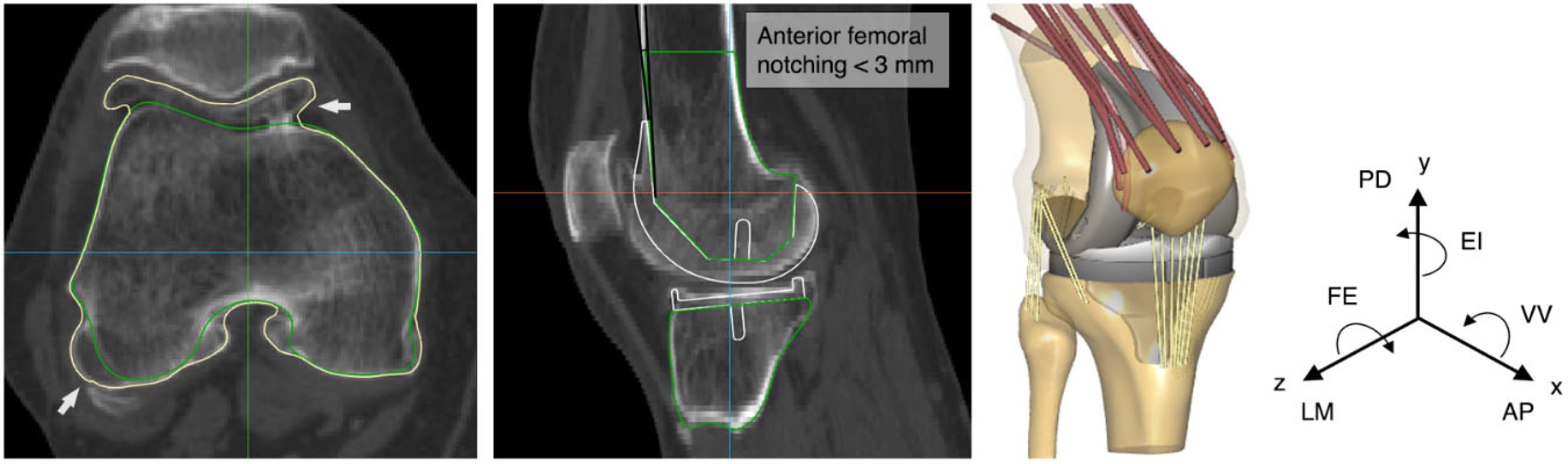
| FE | −3 | +3 | Femoral, Tibial 1 |
| EI | −6 | +6 | Femoral, Tibial |
| VV | −6 | +6 | Femoral, Tibial |
| Surgical Target/ Components | Translations (mm) | Rotations (°) | ||||
|---|---|---|---|---|---|---|
| AP | LM | PD | FE | EI | VV | |
| Surgical target 1 | ||||||
| Femoral | −2.8 | −0.2 | 3.9 | −1.4 | −0.2 | −1.2 |
| Tibial | - | - | - | 5.2 | 2.8 | 2.2 |
| Surgical target 2 | ||||||
| Femoral | −1.7 | −1.8 | 3.6 | −1.5 | −1.6 | −1.5 |
| Tibial | - | - | - | 0.9 | 2.8 | −1.9 |
| Surgical target 3 | ||||||
| Femoral | −1.1 | 0.1 | 2.3 | 0.9 | −1.8 | −0.4 |
| Tibial | - | - | - | −1.8 | −1.5 | 3.2 |
| Surgical target 4 | ||||||
| Femoral | −2.4 | −0.8 | 3.6 | −0.6 | −0.3 | 1.6 |
| Tibial | - | - | - | −2.8 | −0.2 | 2.6 |
| Surgical target 5 | ||||||
| Femoral | −2.3 | −1.5 | 3.7 | −1.9 | −0.5 | −1.4 |
| Tibial | - | - | - | 3.6 | 2.3 | −1.1 |
Disclaimer/Publisher’s Note: The statements, opinions and data contained in all publications are solely those of the individual author(s) and contributor(s) and not of MDPI and/or the editor(s). MDPI and/or the editor(s) disclaim responsibility for any injury to people or property resulting from any ideas, methods, instructions or products referred to in the content. |
© 2023 by the authors. Licensee MDPI, Basel, Switzerland. This article is an open access article distributed under the terms and conditions of the Creative Commons Attribution (CC BY) license (https://creativecommons.org/licenses/by/4.0/).
Share and Cite
Tzanetis, P.; Fluit, R.; de Souza, K.; Robertson, S.; Koopman, B.; Verdonschot, N. Pre-Planning the Surgical Target for Optimal Implant Positioning in Robotic-Assisted Total Knee Arthroplasty. Bioengineering 2023, 10, 543. https://doi.org/10.3390/bioengineering10050543
Tzanetis P, Fluit R, de Souza K, Robertson S, Koopman B, Verdonschot N. Pre-Planning the Surgical Target for Optimal Implant Positioning in Robotic-Assisted Total Knee Arthroplasty. Bioengineering. 2023; 10(5):543. https://doi.org/10.3390/bioengineering10050543
Chicago/Turabian StyleTzanetis, Periklis, René Fluit, Kevin de Souza, Seonaid Robertson, Bart Koopman, and Nico Verdonschot. 2023. "Pre-Planning the Surgical Target for Optimal Implant Positioning in Robotic-Assisted Total Knee Arthroplasty" Bioengineering 10, no. 5: 543. https://doi.org/10.3390/bioengineering10050543