
Analysis of the Hydraulic Efficiency of a Steerable Detention Tank—Simulation Studies

Abstract
:1. Introduction
- verify the possibility of reducing the rainwater volume flow in the drainage system by means of controllable devices enabling cooperation with the drainage system in various hydraulic conditions of the drainage system.
- determining the impact of the connection method (parallel or serial) of the device enabling retention and cooperation with the sewage system on the efficiency of the system.
2. Materials and Methods
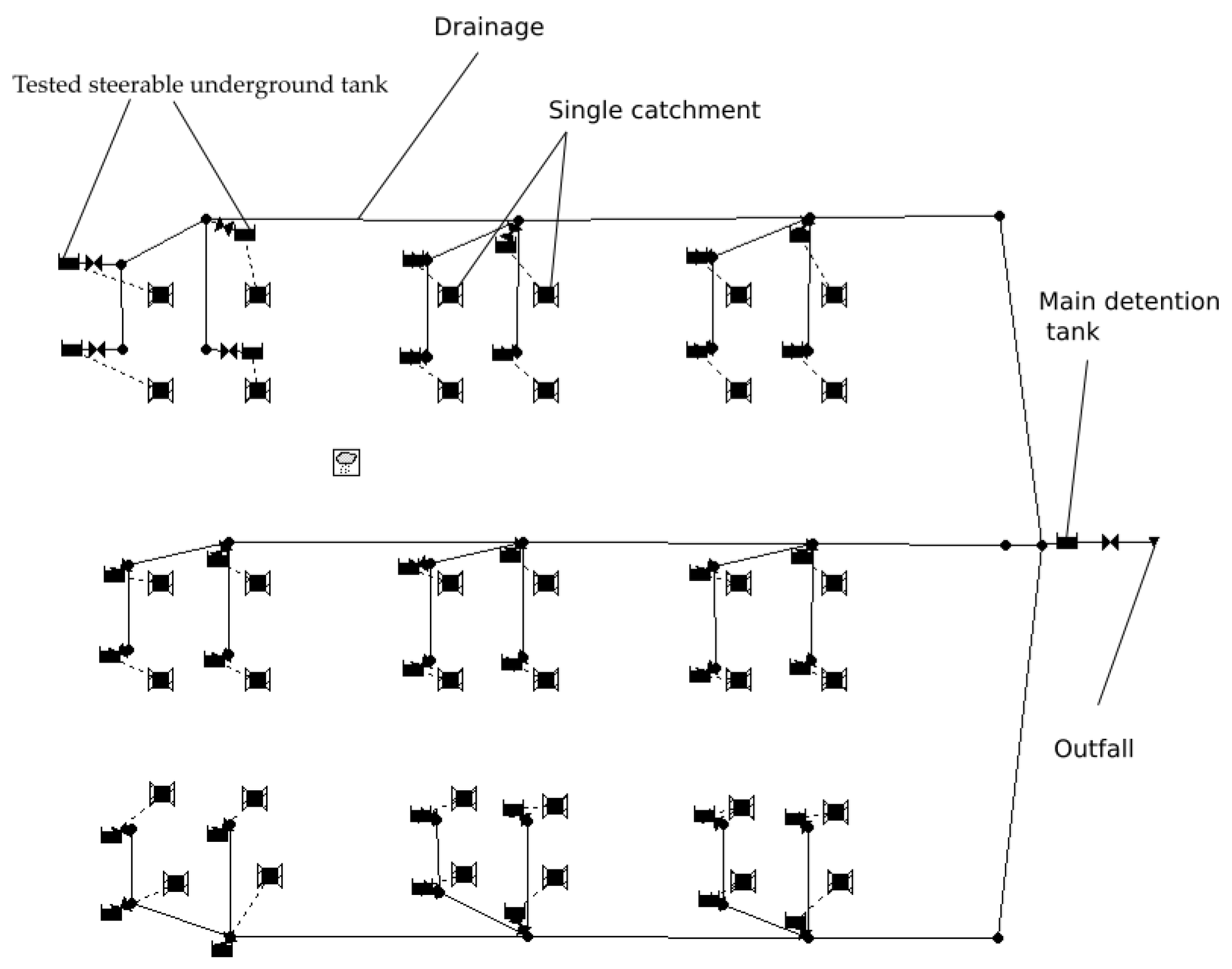
2.1. Tested Device
2.2. Methods
2.3. Key Study
- Description of the WA variant:
- Description of the WB variant:
- Description of the WC variant:
- Analysis of the quantitative reduction of wastewater leakage from the system thanks to the application of the solution in question;
- Analysis of the possibility of reducing the maximum flow rate of sewage at the final node of the drainage system;
- Analysis of the limitation of the capacity of the main tank in cooperation with the solution in question.
3. Result and Discussion
3.1. Analysis of the Quantitative Reduction of Wastewater Discharge from the System Thanks to the Application of the Solution in Question
- Results of the overflow of wastewater from the system in the absence of the introduction of the steerable underground tank for sewage systems.
- The results of wastewater spillage from the system using the steerable underground tank for sewage systems, with a working chamber area of 2 m2.
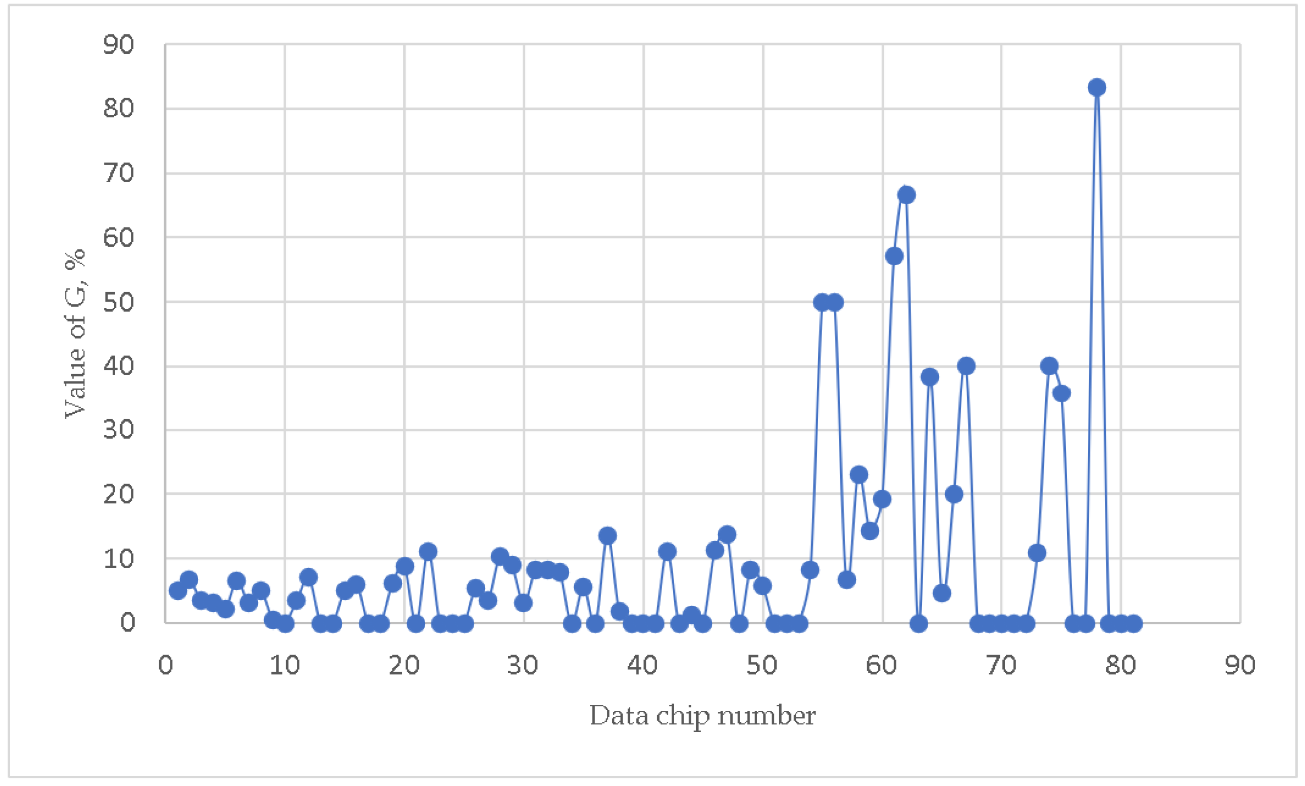
- The results of wastewater spillage from the system using the steerable underground tank for sewage systems, with a working chamber area of 4 m2.
- The results of wastewater spillage from the system using the steerable underground tank for sewage systems, with a working chamber area of 10 m2.
3.2. Analysis of the Quantitative Reduction of Wastewater Discharge from the System Thanks to the Application of the Solution in Question
3.3. Analysis of the Quantitative Reduction of Wastewater Discharge from the System Thanks to the Application of the Solution in Question
4. Conclusions
- The use of steerable underground tanks depending on the hydraulic parameters of the catchment area significantly reduces the amount of wastewater discharged from the sewage system. In the most favourable cases, the reduction of the amount of wastewater poured out may amount to 40% for the surface of the working chamber of 2 m2, 67% for the area of 4 m2, and 83% for the area of 10 m2. This indicates that additional benefits may come from using this solution as high-capacity network objects.
- The use of the steerable underground tank in the WB network connection variant brings greater results than in the WC variant. The analysis based on the K parameter indicated that the reduction in the flow between the variants was as high as 58% (K parameter equal to 0.42). In the least-favourable cases (catchment systems), there was no difference in the reduction of the flow rate resulting from the method of connecting the solution to the network.
- Not in all hydraulic conditions, connecting the device in the WB variant to a greater extent limits the amount of wastewater poured out of the system. The analysis of the ∆V parameter showed that, in some hydraulic systems (i.e., with a specific variation in the hydraulic and hydrological parameters of the catchment area), it is more advantageous to connect the device in the WC variant. Therefore, the choice of the method of connecting the device to the network should be preceded by hydrodynamic analyses of the greater part of the catchment area.
- The application of steerable underground tanks significantly reduces the capacity of the main reservoir (in the analysed systems, it can even reach 60 m3) and allows limiting the amount of rainwater discharged from the system. The maximum value of the reduction in the capacity of the main tank is determined only by the total capacity of all steerable underground tanks used.
- The use of net damming gates can significantly increase the efficiency of the tanks used. Thanks to the use of throttling, reductions of up to 40% can be achieved.
- The effectiveness of the presented solution is strictly dependent on the ratio of the capacities of the presented steerable tank and the capacity of the entire sewage network
Supplementary Materials
Author Contributions
Funding
Data Availability Statement
Conflicts of Interest
References
- Post, A.K.; Knapp, A.K. The importance of extreme rainfall events and their timing in a semiarid grassland. J. Ecol. 2020, 108, 2431–2443. [Google Scholar] [CrossRef]
- Frame, D.J.; Rosier, S.M.; Noy, I.; Harrington, L.J.; Carey Smith, T.; Sparrow, S.N.; Stone, D.A.; Dean, S.M. Climate change attribution and the economic costs of extreme weather events: A study on damages from extreme rainfall and drought. Clim. Change 2020, 162, 781–797. [Google Scholar] [CrossRef]
- Zipser, E.J.; Liu, C. Extreme Convection vs. Extreme Rainfall: A Global View. Curr. Clim. Change 2021, 7, 121–130. [Google Scholar] [CrossRef]
- Bell, C.D.; Tague, C.L.; McMillan, S.K. Modeling runoff and nitrogen loads from a watershed at different levels of impervious surface coverage and connectivity to storm water control measures. Water Resour. Res. 2019, 55, 2690–2707. [Google Scholar] [CrossRef]
- Yin, J.; Fu, P.; Cheshmehzangi, A.; Li, Z.; Dong, J. Investigating the Changes in Urban Green Space Patterns with Urban Land Use Changes: A Case Study in Hangzhou, China. Remote Sens. 2022, 14, 5410. [Google Scholar] [CrossRef]
- López Zavala, M.Á.; Castillo Vega, R.; López Miranda, R.A. Potential of Rainwater Harvesting and Greywater Reuse for Water Consumption Reduction and Wastewater Minimization. Water 2016, 8, 264. [Google Scholar] [CrossRef] [Green Version]
- Hasan, M.A.; Irfanullah, H.M. Exploring the potential for rainwater use for the urban poor in Bangladesh. Water Policy 2022, 24, 645666. [Google Scholar] [CrossRef]
- Cao, Y.; Zhang, Z.; Fu, J.; Li, H. Coordinated Development of Urban Agglomeration in Central Shanxi. Sustainability 2022, 14, 9924. [Google Scholar] [CrossRef]
- Li, J.; Ouyang, X.; Zhu, X. Land space simulation of urban agglomerations from the perspective of the symbiosis of urban development and ecological protection: A case study of Changsha Zhuzhou Xiangtan urban agglomeration. Ecol. Indic. 2021, 126, 107669. [Google Scholar] [CrossRef]
- Not a drop to spare. Nat. Sustain. 2018, 1, 151152.
- Xing, Y.; Shaob, D.; Liangc, Q.; Chenc, H.; Mad, X.; Ullahe, I. Investigation of the drainage loss effects with a street view based drainage calculation method in hydrodynamic modelling of pluvial floods in urbanized area. J. Hydrol. 2022, 605, 127365. [Google Scholar] [CrossRef]
- Sein, Z.M.M.; Zhi, X.; Ullah, I.; Azam, K.; Ngoma, H.; Saleem, F.; Xing, Y.; Iyakaremye, V.; Syed, S.; Hina, S.; et al. Recent variability of sub-seasonal monsoon precipitation and its potential drivers in Myanmar using in-situ observation during 1981–2020. Int. J. Clim. 2022, 42, 3341–3359. [Google Scholar] [CrossRef]
- Zevenbergen, C.; Fu, D.; Pathirana, A. Transitioning to Sponge Cities: Challenges and Opportunities to Address Urban Water Problems in China. Water 2018, 10, 1030. [Google Scholar] [CrossRef] [Green Version]
- Meng, B.; Li, M.; Du, X.; Ye, X. Flood Control and Aquifer Recharge Effects of Sponge City: A Case Study in North China. Water 2022, 14, 92. [Google Scholar] [CrossRef]
- Qi, Y.; Shun Chan, F.K.; Griffiths, J.; Feng, M.; Sang, Y.; O’Donnell, E.; Hutchins, M.; Thadani, D.R.; Li, G.; Shao, M.; et al. Sponge City Program (SCP) and Urban Flood Management (UFM)—The Case of Guiyang, SW China. Water 2022, 13, 2784. [Google Scholar] [CrossRef]
- Drumond, P.P.; Moura, P.M.; Silva, T.F.G.; Ramires, J.C.; Silva, L.R.V. Citizens’s perception on stormwater management and use of onsite stormwater detention in Belo Horizonte/Brazil. Braz. J. Water Resour. 2022, 27, 115. [Google Scholar]
- Drumond, P.P.; Moura, P.M.; Coelho, M.M.L.P. Comparison the monitoring data of an onsite stormwater detention (OSD) and the results in the use of theoretical methods for its design. Braz. J. Water Resour. 2018, 23, 112. [Google Scholar]
- Ngu, J.O.K.; Mah, D.Y.S.; Liow, C.V.; Ngu, I.T. Modelling of OnSite Stormwater Detention Underneath a Car Porch. Int. J. Innov. Technol. Explor. Eng. 2019, 12, 43044307. [Google Scholar]
- Rodney, R.; Rowlands, A.; Zhang, H. Onsite stormwater detention for Australian development projects: Does it meet frequent flow management objectives? Water Sci. Eng. 2019, 1, 110. [Google Scholar]
- Bonane, T.; Pizzo, H.; Meireles, M.; Rochal, L. Damping of the rainwater runoff by small underground reservoirs in subdivisionlots. Hidraul. Mag. 2022, 3, 4857. [Google Scholar]
- di Matteo, M.; Liang, R.; Maier, H.R.; Thyer, M.A.; Simpson, A.R.; Dandy, G.C.; Ernst, B. Controlling rainwater storage as a system: An opportunity to reduce urban flood peaks for rare, long duration storms. Environ. Model. Softw. 2018, 111, 3441. [Google Scholar] [CrossRef]
- Pochwat, K. Assessment of Rainwater Retention Efficiency in Urban Drainage Systems—Model Studies. Resources 2022, 11, 14. [Google Scholar] [CrossRef]
- Pochwat, K.; Iličić, K. A simplified dimensioning method for high efficiency retention tanks. E3S Web Conf. 2018, 45, 00065. [Google Scholar] [CrossRef]
- Pochwat, K. Hydraulic analysis of functioning of the drainage channel with increased retention capacity. E3S Web Conf. 2017, 17, 00075. [Google Scholar] [CrossRef] [Green Version]
- Szeląg, B.; Górski, J.; Bak, Ł.; Górska, K. Modelling of stormwater quantity and quality on the example of urbanised catchment in Kielce. Ecol. Chem. Eng. A 2013, 20, 13051316. [Google Scholar]
- Zhang, X.; Bao, W.; Qu, S.; Yu, Z. One dimensional hydrodynamic model accounting for tidal effect. Hydrol. Res. 2012, 43, 113122. [Google Scholar] [CrossRef]
- Rakha, M.A.; Rathie, A.K. Extensions of Euler type II transformation and Saalschütz’s theorem. Bull. Korean Math. Soc. 2011, 48.1, 151–156. [Google Scholar] [CrossRef]
- Dziopak, J.; Słyś, D. Stormwater management and retention in urban catchment. Storm Water Manag. 2015, 835, 4366. [Google Scholar]
- Stanowska, P.; Dziopak, J.; Słyś, D.; Starec, M. An innovative rainwater system as an effective alternative for cubature retention facilities. Stud. Geotech. Et Mech. 2021, 43, 532–547. [Google Scholar] [CrossRef]


| Number | Catchment Area | Conduit Gradient | Catchment Gradient | Length of Conduits |
|---|---|---|---|---|
| ha | ‰ | % | m | |
| 1 | 10 | 2 | 0.5 | 100 |
| 2 | 15 | 2 | 0.4 | 100 |
| 3 | 5 | 2 | 0.3 | 100 |
| 4 | 10 | 2 | 0.4 | 150 |
| 5 | 5 | 2 | 0.5 | 150 |
| 6 | 15 | 2 | 0.3 | 150 |
| 7 | 15 | 2 | 0.5 | 200 |
| 8 | 5 | 2 | 0.4 | 200 |
| 9 | 10 | 2 | 0.3 | 200 |
| 10 | 10 | 3 | 0.4 | 100 |
| 11 | 15 | 3 | 0.3 | 100 |
| 12 | 5 | 3 | 0.5 | 100 |
| 13 | 10 | 3 | 0.3 | 150 |
| 14 | 15 | 3 | 0.5 | 150 |
| 15 | 5 | 3 | 0.4 | 150 |
| 16 | 15 | 3 | 0.4 | 200 |
| 17 | 10 | 3 | 0.5 | 200 |
| 18 | 5 | 3 | 0.3 | 200 |
| 19 | 10 | 4 | 0.3 | 100 |
| 20 | 5 | 4 | 0.4 | 100 |
| 21 | 15 | 4 | 0.5 | 100 |
| 22 | 5 | 4 | 0.3 | 150 |
| 23 | 10 | 4 | 0.5 | 150 |
| 24 | 15 | 4 | 0.4 | 150 |
| 25 | 5 | 4 | 0.5 | 200 |
| 26 | 10 | 4 | 0.4 | 200 |
| 27 | 15 | 4 | 0.3 | 200 |
| The Value of the G Parameter | |
|---|---|
| Minimum value | 0% |
| Average value | 7.7% |
| Maximum value | 40% |
| The Value of the G Parameter | |
|---|---|
| Minimum value | 0% |
| Average value | 15.27% |
| Maximum value | 67% |
| The Value of the G Parameter | |
|---|---|
| Minimum value | 0% |
| Average value | 15.60% |
| Maximum value | 83% |
| Area of Steerable Underground Tank Chamber, m2 | 1 | 2 | 3 | 4 | 10 |
|---|---|---|---|---|---|
| Minimum value | 0.433 | 0.424 | 0.424 | 0.428 | 0.438 |
| Average value | 0.910 | 0.907 | 0.908 | 0.905 | 0.916 |
| Maximum value | 0.994 | 0.999 | 0.996 | 0.993 | 0.999 |
| Number of Tested Systems (Data Chip Number) | Maximum Value of the Inflow Intensity, dm3/s | ||
|---|---|---|---|
| WB | WC | ||
| U8 | 0 | 120.314 | 120.314 |
| U89 | 1 | 113.426 | 119.145 |
| U170 | 2 | 112.332 | 118.615 |
| U251 | 3 | 112.339 | 117.386 |
| U332 | 4 | 111.792 | 116.415 |
| U413 | 10 | 105.081 | 109.296 |
Publisher’s Note: MDPI stays neutral with regard to jurisdictional claims in published maps and institutional affiliations. |
© 2022 by the authors. Licensee MDPI, Basel, Switzerland. This article is an open access article distributed under the terms and conditions of the Creative Commons Attribution (CC BY) license (https://creativecommons.org/licenses/by/4.0/).
Share and Cite
Pochwat, K.; Pizzo, H. Analysis of the Hydraulic Efficiency of a Steerable Detention Tank—Simulation Studies. Hydrology 2022, 9, 217. https://doi.org/10.3390/hydrology9120217
Pochwat K, Pizzo H. Analysis of the Hydraulic Efficiency of a Steerable Detention Tank—Simulation Studies. Hydrology. 2022; 9(12):217. https://doi.org/10.3390/hydrology9120217
Chicago/Turabian StylePochwat, Kamil, and Henrique Pizzo. 2022. "Analysis of the Hydraulic Efficiency of a Steerable Detention Tank—Simulation Studies" Hydrology 9, no. 12: 217. https://doi.org/10.3390/hydrology9120217