
An Overview of Hydrogen Energy Generation

Department of Mechanical Engineering, Prince Mohammad Bin Fahd University, Al Khobar P.O. Box 1664, Saudi Arabia
ChemEngineering 2024, 8(1), 17; https://doi.org/10.3390/chemengineering8010017
Submission received: 18 November 2023
/
Revised: 9 January 2024
/
Accepted: 24 January 2024
/
Published: 1 February 2024
(This article belongs to the Special Issue Advances in Hydrotreating Catalyst Synthesis for Fuel and Chemical Production Processes)
Abstract
:The global issue of climate change caused by humans and its inextricable linkage to our present and future energy demand presents the biggest challenge facing our globe. Hydrogen has been introduced as a new renewable energy resource. It is envisaged to be a crucial vector in the vast low-carbon transition to mitigate climate change, minimize oil reliance, reinforce energy security, solve the intermittency of renewable energy resources, and ameliorate energy performance in the transportation sector by using it in energy storage, energy generation, and transport sectors. Many technologies have been developed to generate hydrogen. The current paper presents a review of the current and developing technologies to produce hydrogen from fossil fuels and alternative resources like water and biomass. The results showed that reformation and gasification are the most mature and used technologies. However, the weaknesses of these technologies include high energy consumption and high carbon emissions. Thermochemical water splitting, biohydrogen, and photo-electrolysis are long-term and clean technologies, but they require more technical development and cost reduction to implement reformation technologies efficiently and on a large scale. A combination of water electrolysis with renewable energy resources is an ecofriendly method. Since hydrogen is viewed as a considerable game-changer for future fuels, this paper also highlights the challenges facing hydrogen generation. Moreover, an economic analysis of the technologies used to generate hydrogen is carried out in this study.
1. Introduction
Hydrogen is known as the lightest and the most abundant element. It supplies energy to fuel the stars and the Sun. It is considered non-toxic, odorless, colorless, highly combustible, and unpolluted. Also, it is an energy carrier [1]; it scarcely exists by itself and should be generated from compounds that contain it. Hydrogen is versatile; it can be produced from varied resources, and it is used in a wide range of applications. It can be converted into electricity using conversion devices like fuel cells [2]. The main advantages of hydrogen are its high electrochemical reactivity, theoretical energy density, safe combustion products, and unbounded availability. However, hardness storage, low density under normal circumstances, and explosion hazards represent the main impediments to the use of hydrogen in fuel cells. Many sources could be used to generate hydrogen, like water, fossil fuels, and renewable energy. According to its production method, hydrogen can be classified as follows [3]:
- -
- Gray hydrogen: fossil fuels are used to produce hydrogen, like natural gas and oils; this kind of hydrogen releases a large amount of CO2 into the air during its production process.
- -
- Blue hydrogen: hydrogen is produced using fossil fuels, and it is accompanied by carbon-capture storage technology to decrease carbon dioxide emissions.
- -
- Green hydrogen: hydrogen is generated by electrolysis powered by renewable energy, such as solar, wind, geothermal, nuclear, and waste energy. It is considered to be a clean technology to generate hydrogen.
- -
- Brown hydrogen: this type of hydrogen is considered to be the most affordable and the most harmful to the environment due to the thermal coal that is used in the generation process.
- -
- Turquoise hydrogen: hydrogen is fabricated using methane pyrolysis technology that yields solid carbon.
- -
- Yellow hydrogen: this refers to the hydrogen generated by electrolysis using solar energy.
- -
- White hydrogen: this type of hydrogen is geological, which is established in underground deposits and formed via fracking. Presently, there are procedures to harness and exploit it.
Hydrogen energy is versatile in terms of its usage and generation. Currently, it is used in the production of methanol and ammonia, the fabrication of vitamins and pharmaceutical products, and the hydrogeneration process of liquid oils. Also, hydrogen is used to extract sulfur and nitrogen compounds in refinery processes [4]. It is used to produce steel by replacing coking coal and to generate fuel for transportation. Moreover, some companies are planning to use hydrogen to heat and cool buildings and to generate power to minimize GHG emissions and improve efficiency.
Hydrogen energy is anticipated to be a sustainable fuel for the future. Recently, the development of hydrogen technologies has gained more international interest and attention due to the significant role that hydrogen can play in increasing energy security and economic sustainability. Hence, hydrogen energy can sustainably cope with the global growth in energy demand. In addition, hydrogen energy can be used to generate and store energy and to deal with the intermittent nature of renewable energy sources [5]. Also, hydrogen can contribute to decarbonization in many sectors, including chemical, transportation, and steel production, and therefore, it can enhance air quality, boost energy security, minimize oil reliance, and cope with climate change. Moreover, hydrogen can be produced from plastic waste materials through several thermo–catalytic processes; therefore, it is considered to be a solid waste treatment [6].
The neutral carbon characteristic of hydrogen depends on the cleanliness of its generation method, the feedstock used, and the energy used in its generation process [7]. Therefore, it is essential to determine the hydrogen origin before considering it as a green energy source. The kind of feedstock and energy and the desired end-use purity determine the specified technology and hydrogen generation method. The objective of this paper is to present a complete review of the operated and developed technologies used to generate hydrogen with a focus on the feedstock and energy used, the advantages and drawbacks of each technology, and its maturity. Moreover, the different uses of hydrogen and the different challenges facing hydrogen energy generation are discussed in the current paper. Also, since hydrogen is predicted to play a crucial role in the future, and since the economic aspect is considered an important factor in expanding the hydrogen market, an economic analysis is carried out in this paper.
2. Current and Future Uses of Hydrogen and Its Generation
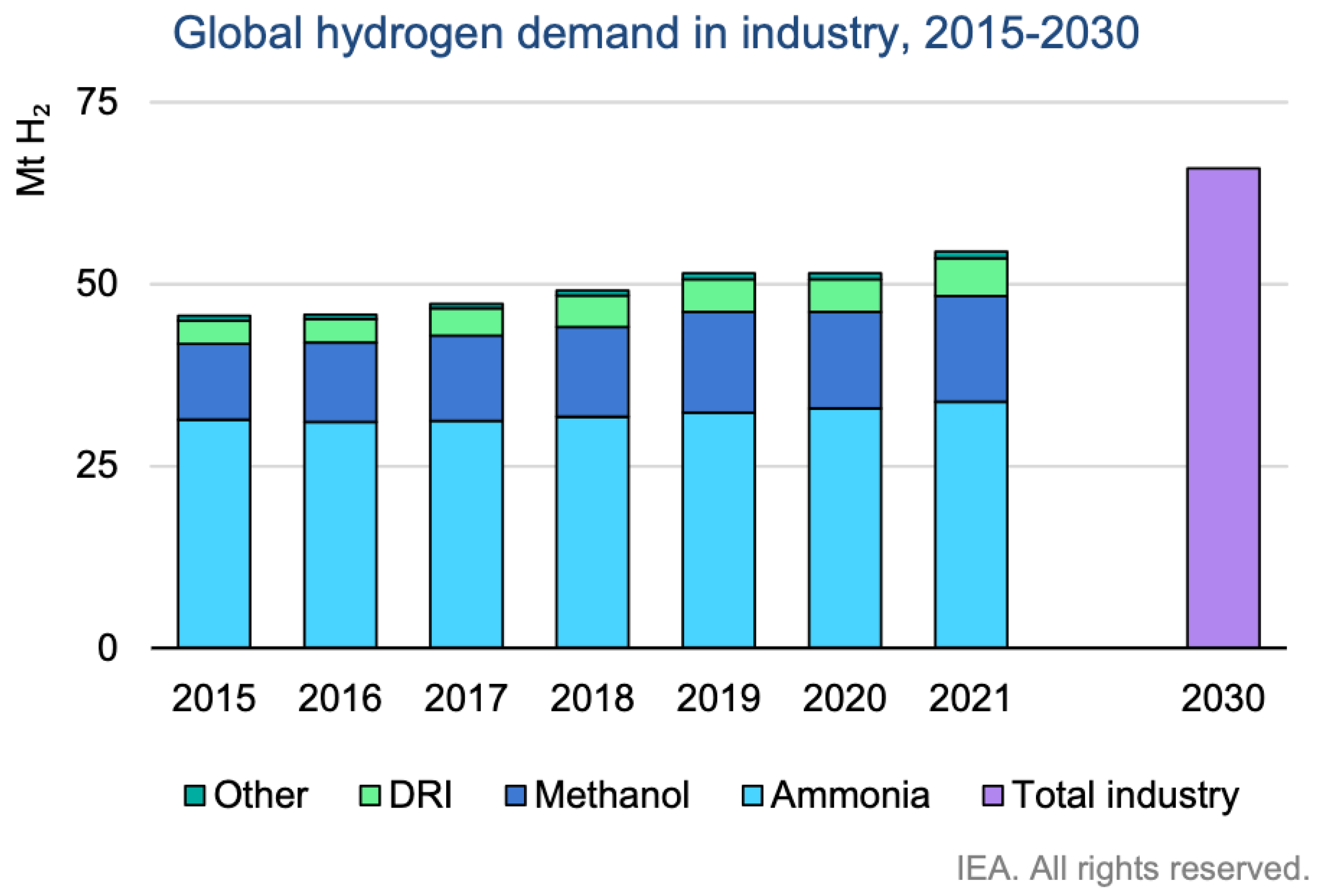
Hydrogen can be fabricated and utilized on site. The main uses of hydrogen are oil refining and ammonia production, which account for two thirds of hydrogen usage [8]. Hydrogen is combined with heavier oil in petroleum refineries to generate transport fuel. Ammonia can be used as a fertilizer in agriculture, as a refrigerant gas, and in the fabrication of explosives, pesticides, plastics, and other chemicals. Figure 1 displays the global annual production of hydrogen and its usage between 2015 and 2030. Hydrogen generation will increase: it reached 55 Mt of H2 in 2021 and is expected to reach 70 Mt of H2 by 2030. In addition, it is noticeable that the main use of hydrogen is for ammonia production.
Overall hydrogen production is expected to increase from USD 150.20 billion in 2021 to USD 220.37 billion by 2028 [9]. Also, the overall hydrogen market bulk is anticipated to attain USD 184.11 billion by 2028 [9].
Figure 1.
Annual hydrogen production and uses between 2015 and 2030 [10].
Figure 1.
Annual hydrogen production and uses between 2015 and 2030 [10].

The hydrogen market scale is divided into three categories [11]:
− Small scale: the hydrogen capacity ranges from 0.5 MW to 1.7 MW, and the hydrogen is used in hydrogen filling stations.
− Medium scale: the hydrogen capacity ranges from 33 MW to 1000 MW, and the hydrogen is used for refineries.
− Large scale: the hydrogen capacity ranges from 66 MW to 333 MW, and the hydrogen is used in industrial fields.
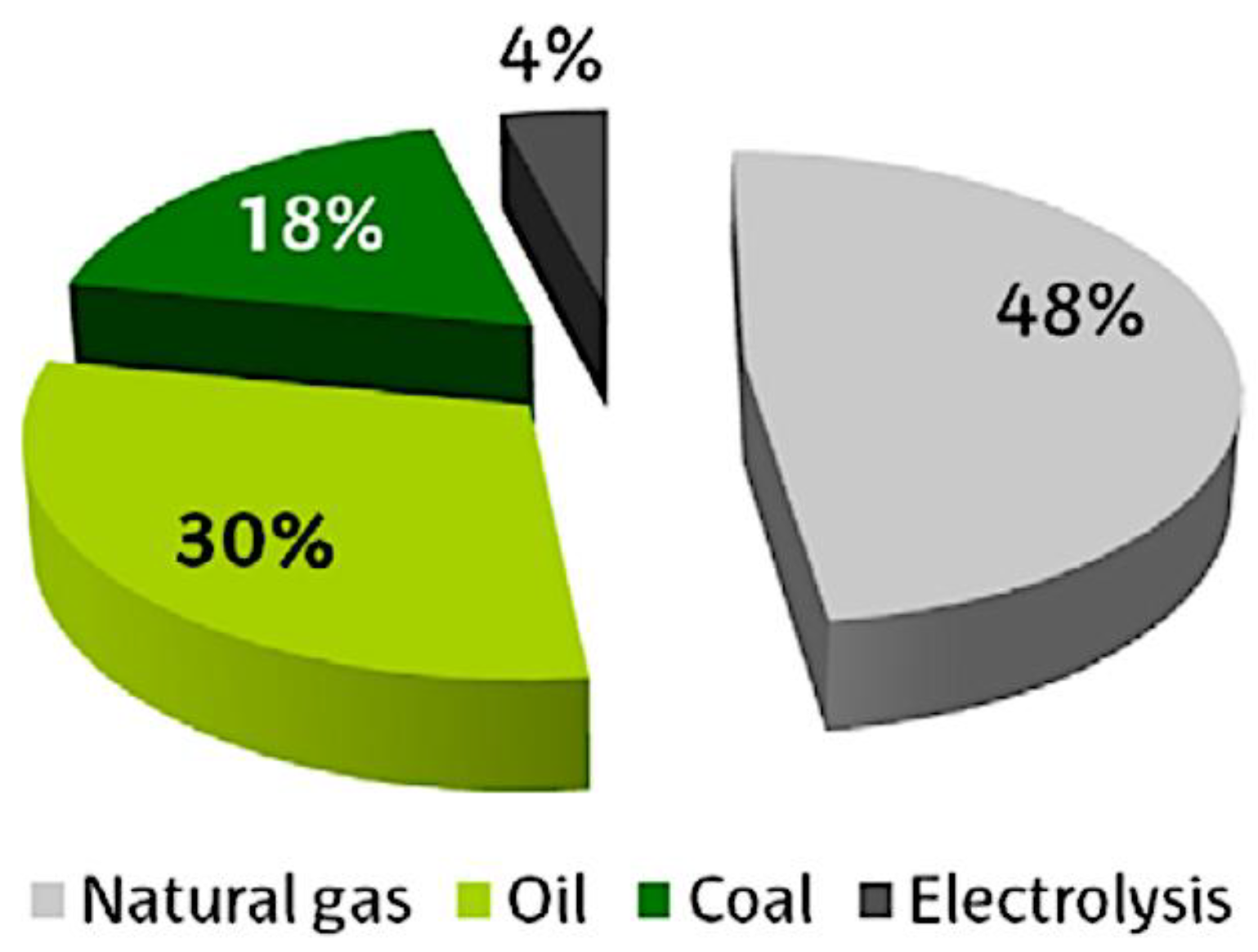
Several feedstocks are used to fabricate hydrogen, like water, fossil fuels (natural gas, crude oil, and coal), and biomass. Figure 2 displays the current feedstock used in hydrogen production. Non-renewable sources are mainly used in the hydrogen generation process. A total of 48% are from natural gas, 30% are from crude oil, 18% are from coal, and 4% are from water electrolysis [12]. In water electrolysis, the water is used to generate hydrogen, and it requires electricity that is generated from fossil fuels or renewable energy.
3. Main Approaches for Hydrogen Production
Many technologies are used to produce hydrogen, involving the steam reformation of methane sources, coal and coke gasification, catalytic decomposition of natural gas, partial oxidation of hydrocarbon, and water electrolysis. According to many research studies, the largest quantity of hydrogen is produced by steam reformation at 48%, followed by petroleum fraction at 30%, and coal gasification at 18%. The lowest is produced using water electrolysis [13,14].
The prime technologies of hydrogen generation use non-renewable energy, are very energy intensive, and have a high temperature demand [13]. Consequently, the use of these technologies contributes to polluting the air by emitting enormous quantities of ashes and greenhouse gas emissions, including oxide carbon, nitrogen, sulfur, and heavy materials. However, other technologies use renewable resources to generate hydrogen, such as photo-electrolysis, thermochemical, and water splitting. Some of these technologies are still at laboratory scale [15,16].
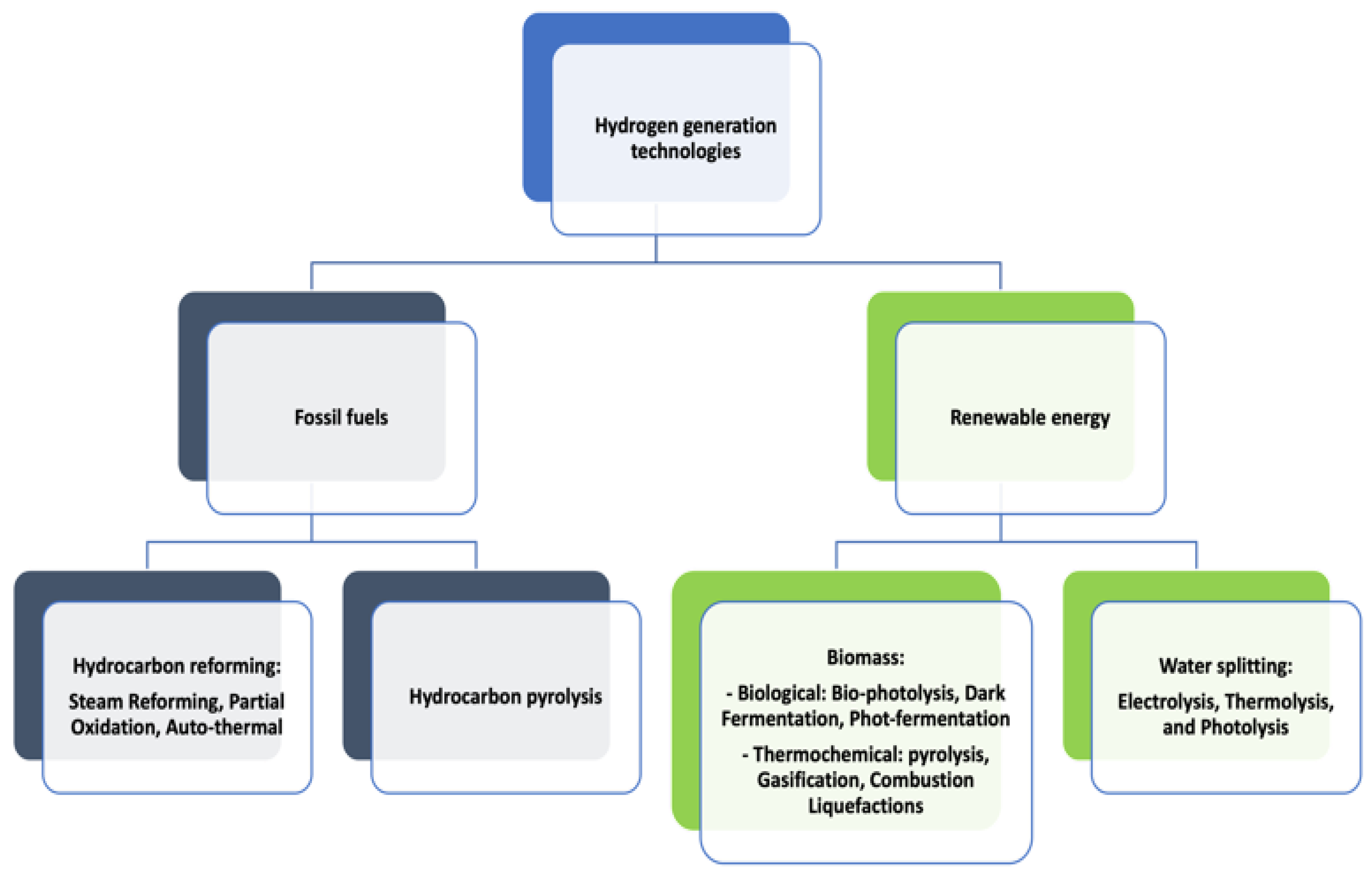
The classification of hydrogen generation is based on many factors, such as the technologies used and the sources of energy used. There are mainly two power sources used in the process of hydrogen generation: fossil fuel and renewable energy (Figure 3). The technologies used for hydrogen production can be classified into three groups: electrolytic, photolytic, and thermal process.
3.1. Electrolytic Technique
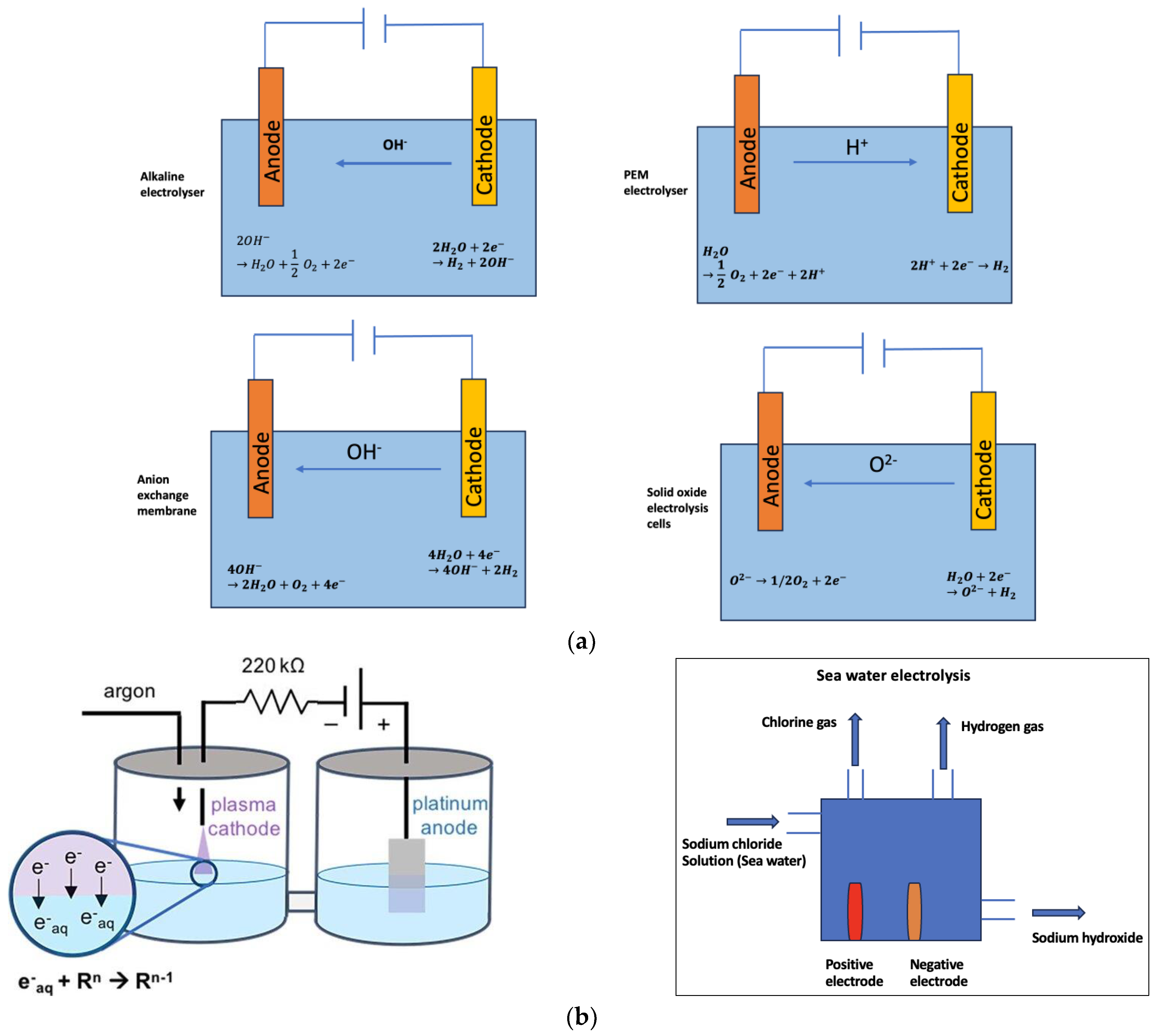
In this technique, hydrogen is generated by feeding the electrolyzer with electricity to dissociate water molecules into hydrogen and oxygen. Water comprises two atoms of hydrogen and one atom of oxygen, and the dissociation of water will yield hydrogen and oxygen. Since the two atoms are robustly bonded, stimulus and external agents are required to facilitate the splitting of the water molecule. The external agents could be electrical energy generated from renewable and non-renewable energy sources. Water electrolysis comprises a cathode and an anode joined through a power supply and submerged in a conducting electrolyte. The types of electrolytes used are an oxygen ion exchange ceramic membrane, a proton-exchange membrane (PEM), and an aqueous solution containing ions. After a direct current is applied, the electrons move from the negative terminal of the power supply to the cathode to form hydrogen. The electrons, generated by the electrochemical reaction, go back to the positive terminal of the DC supply. This technique can be sustainable and clean if the electricity used is produced from renewable energy sources. This technology is envisaged to be cheaper and more performant if renewable energy resources are used, as power prices decrease during windy and sunny days. The performance of electrolysis can be estimated using two methods: Faradaic efficiency and energy efficiency of the cell. Faradaic efficiency is described as the fraction of the number of moles of hydrogen generated by the charge passed. A Faradaic efficiency of 100% means that every electron obtained by water oxidation is converted to a conformable proton to generate hydrogen. Faradaic efficiency is usually less than 100% owing to parasitic electrochemical processes, such as the degeneration of elements of the electrochemical processes. The energy efficiency of the cell is the ratio of the obtainable energy from the hydrogen generated by the cell, using the heating value of hydrogen, to the energy expended by the cell [17]. Water electrolysis can be classified into three classes based on the operating temperature: low temperature (lower than 300 °C), intermediate temperature (300–700 °C), and high temperature (higher than 700 °C and below 1000 °C) [18]. There are six main technologies used in the water electrolysis domain: the alkaline electrolyzer, electrolysis with a proton-exchange membrane (PEM) water electrolysis, steam electrolysis using a solid oxide electrolysis cell (SOEC), anion exchange membrane (AEM), plasma electrolysis, and seawater electrolysis (Figure 4a,b).
Water electrolysis under alkaline conditions: Strong electrolytes, such as sodium or potassium for positive ions, and hydroxide or chlorides as negative ions, are used in this process to strengthen the solution to be able to transmit the ions with high motility. A diaphragm is used to separate the anode and cathode. The alkaline electrolyte comes in the cathode and anode areas, and water molecules can penetrate through the diaphragm to the other region. When an electric current is applied, electrons move from the negative terminal of the DC course to the cathode and combine with the water molecule to create hydrogen and hydroxide ions. Then, the hydroxide ions are moved to the anode by migration since they have an opposite charge. In the anode, the hydroxide ions lose electrons and form oxygen and water. The gas produced by the electrolysis is not able to move in a large quantity through the diaphragm to the other area due to the impediment of the porous diaphragm. Hydrogen and oxygen are composed and collected by gas receivers as oxygen on the anode and hydrogen on the cathode. Nickel is used normally as electrode material thanks to its good activity, easy accessibility, and its low cost. A concentrated solution of potassium hydroxide (KOH) is normally used as an electrolytic solution due to its high conductivity and fewer corrosion issues compared to other electrolytic solutions. This technology is characterized by simplicity and low investment cost. The purity level of oxygen and hydrogen can attain 99.7 and 99.9 vol.%, respectively. The operating temperature is in the range of 80–90 °C, and the operating pressure is around 3.4 MPa. The performance of hydrogen generation is in the range of 45–80% [21]. This technology is more effective when operating under low current densities (0.3 A/cm2) [22]. The disadvantage of this technology is the highly corrosive effect of liquid electrolytes that shortens their lifetime. Also, the cross-diffusion of oxygen and hydrogen between electrodes decreases the purity of hydrogen, resulting in security matters linked to hydrogen explosion [23]. An acidic/alkaline atmospheric water electrolysis is developed to generate hydrogen, in which hydrogen is generated within an acidic solution, oxygen is released under alkaline conditions, and a membrane is used in the center of the electrolyzer to curb neutralization [24]. This advanced technology generates four times more hydrogen than that of alkaline aqueous solution with 30% less energy consumption under the current density of 200 mA/cm2. An efficient catalyst can contribute to minimizing the overpotential of the OER and HER in water splitting and enhance energy efficiencies. According to the authors of [25], the catalysts Pt and IrO2/RuO2 demonstrate high efficiency with low cost. The effect of temperature on the efficiency on alkaline water electrolysis has been theoretically studied by [26] through a developed model. Results have revealed that the rise of operating temperature leads to improved system efficiency in the case of relatively high current density. The catalytic activity of the role of the NiCoP catalyst for the hydrogen evolution reaction in alkaline water electrolysis has been examined [27]. Results showed that the integration of the catalyst nanoparticle on the carbon fiber support is efficient in the electrode preparation and, therefore, increases the catalytic activity. The authors of [28] conducted a study to estimate the impact of operating pressure on an alkaline water electrolysis system using a developed numerical model. A comparison between the current–voltage polarization curve and the experimental data is used to validate the developed system. Results showed that using high-pressure water electrolysis acquires high-purity hydrogen without the need for a water-adsorption device. In addition, the system becomes more performant with suitable pressure, owing to the reduction of the power consumption of the balance of plant.
Proton-exchange membrane electrolyzer: in this process, a gas-tight thin polymeric membrane with a cross-connected frame and effective acid character is used as an electrolyte. Water is oxidized at the anode to generate oxygen, electrons, and protons that move along the membrane to the cathode, where they are diminished and generate hydrogen that babbles towards the cathodic gas manifold. The PEM electrolyzer is most suitable for low-scale hydrogen generation. The maximum hydrogen yield is around 30 Nm3/h, and the power consumption is 174 kW [21]. The efficiency is in the range of 48–65%. The electrolysis temperature is limited to below 80° due to the existence of the polymeric membrane. The hydrogen purity reaches values up to 99.99 vol.% in the absence of auxiliary equipment thanks to the solid polymer membrane, which can efficiently avert gas diffusion [21]. Also, PEM can be performed at a high current density to enhance the hydrogen generation rate. The hazard of the formation of a flammable mixture is low due to the weak gaseous permeability of the polymeric membranes. The main feature of the PEM electrolyzer derives from its capability to perform under a changeable power feeding pattern. However, PEM electrolyzers are characterized by high investment costs and shorter lifespans, resulting from noble metal catalysts, indispensable PEM, and corrosion-resistant current. The use of molecular catalysts is viewed as a promising solution to the drawbacks of PEM [29]. Lately, several molecular water oxidation catalysts and HOR catalysts, which can bear high acidity, have evolved [30]. The coupling of PEM with renewable energy sources is viewed as a promising system thanks to its resilient response and high current densities. However, this hybrid system faces the challenge of degradation caused by operating with volatile current and constant current. According to [31,32], degradation rates between 0 mV/h and 230 mV/h were apprised under constant current. This can be explained by the oxidation of the porous titanium, which acted as the transport player and the fluffy membrane [33]. In addition, the degradation can be caused by mechanical degeneration [34], active material losses [18], and material caducity [35]. The rise in operating temperature has a positive impact on the efficiency and the power efficiency of the PEM system owing to the low quantity of electricity needed by a cell that lessens with the rise of temperature [36]. Nevertheless, the increase of temperature above 100 °C negatively affects the stability of membrane. Heat is produced in the current contractor through the operating of the PEM owing to joule heating. The area of the membrane alongside the current contactor and the current contractor will have the same temperature. Although the inner part of the PEM is submerged in water, the area of the membrane compressed on the current contactor is revealed to have a localized greater temperature, causing it to be more sensitive to degeneration. Therefore, monitoring and evaluating the heat generation rate and the stack temperature is important. Even though the PEM is recognized for its dynamic nature, a high rise of current supply will lead to a fast rise of the heat production and the operating temperature, resulting in negatively affecting the stability and the longevity of the membrane.
Solid oxide electrolyzers (SOEs) are presented as an advanced concept of water electrolyzers to increase efficiency by enabling water or steam electrolysis at high temperatures (600–900 °C) [37]. Since water splitting is an endothermic reaction, an increase in temperature leads to a decrease in the decomposition voltage and the electricity demand. Therefore, a remarkable improvement in power-to-hydrogen efficiency (up to 95%HHVH2) with external heat of 150–180° is attained, resulting in a decrease in the cost of hydrogen generation [38]. The working principle of SOEs is based on feeding the cathode with steam and recycled hydrogen, and the water is reduced to produce hydrogen. The oxide anions, produced in the cathode, move to the anode through the solid electrolyte, where they combine to form oxygen and close the circuit with the released electrons. In addition to the high efficiency ensured by SOEC, expensive noble metal electrocatalysts are not required thanks to the high running temperature. The two different architectures of SOEC are the cathode-supported cell (CSC) and the electrolyte-supported cell (ESC). The main difference between these two architectures is the thicker layer. The CSC comprises a thick cathode upon which a thin anode and electrolyte are placed. However, the ESC encompasses a thick electrolyte upon which a thin anode and cathode are placed. The electrolytes that are widely used in this technology are ceramic material, Ni-based cermet, combined yttria-stabilized zirconia (YSZ, 8 mol.% yttria-doped), and gadolinium-doped ceria. The main benefits of YSZ are the conscientious stable efficiency under temperatures ranging between 700 and 850 °C owing to a high ionic conductivity (10−2–10−1 S cm−1). Gadolinium-doped ceria is considered to be a useful electrolyte material owing to its high conductivity, while it has a high sintering temperature (~1500 °C) that is considered to be a challenge since it limits co-sintering possibilities. Compared to traditional electrolyzers, this technology can perform effectively with high power density. Notably, intense temperature waste heat is supplied. This can be explained by the fact that the electrochemical transformation of water under high-temperature conditions allows the storage of electricity and heat in the generated hydrogen [39]. Since this technology is a high-temperature type of electrolysis, it causes the rapid degradation of cells. Nuclear heat is one of the leading nominees to run SOEC on a large scale, where heat is a byproduct. In addition, it can be incorporated with solar collectors with the aim of storing energy and generating secondary fuel. The causes of degradation of SOEs can be categorized into three classes: structural degradation, mechanical failure due to thermal stress, and chemical/electrochemical degradation. The degradation of SOE cells depends on cell material, cell operating conditions, and processing. The longevity of SOE cells during operation is affected by current density, gas supplied, operating temperature, cell polarization, and steam-to-hydrogen transformation rate [40]. However, the stack degradation is a result of seals, interconnect contact degeneration, and speeded-up cell degeneration due to pollution from tubing [41]. Despite the fact that the SOE is a promising technology for wide-ranging hydrogen generation, it is still in the development stage.
Anion exchange membrane (AEM) electrolysis is a propitious technology for large-scale hydrogen generation. This technology integrates the merits of alkaline and PEM electrolysis in a cell formed of a hydrocarbon-based anion exchange membrane and two transition metals [42,43]. The benefits of this technology arise from the use of distilled water or milder alkaline electrolytes rather than a concentrated KOH solution and the feasibility of using an affordable catalyst, as in alkaline electrolysis, and the use of a solid polymer electrolyte architecture, as in PEM electrolysis [44]. It is a cheap technology and has low interchange with atmospheric CO2 [45]. Nevertheless, the disadvantages of current AEM are low power performance, low ionic conductivity, important catalyst loading, and moderate-range membrane stability with significant ohmic resistance loss [43]. An increase in temperature increases the efficiency of AEM, and the integration of ionomers in the electrode could enhance ion transport between the electrode and the membrane [46]. The main weakness of AEMs is their restricted thermal stability, particularly at high pH [47]. The degradation of AEMs at high temperatures and under fundamental circumstances is mainly caused by two reasons: nucleophilic attack of hydroxide on N-alkyl groups and Hofmann elimination [48]. Moreover, the electrochemical oxidation of the immersed phenyl group oxygen evolution catalyst can lead to the degradation of AEMs [49]. The development of stabilized functional groups on the polymer backbone enhances the chemical stability of AEMs under alkaline circumstances, resulting in using this membrane under high temperatures for long duration. AEMs should be fed with pure water, and the use of ionomer/binder material is necessary. The use of pure water engenders low current densities and the use of suitable liquid electrolyte conduct to improve the performance of AEMs, such as 1% K2CO3 or dilute KOH solutions.
Plasma electrolysis is viewed as an alternative and promising method for hydrogen generation thanks to its ability to generate more hydrogen using less energy consumption compared to hydrocarbon electrolysis. Plasma electrolysis can generate hydrogen 149 times more than hydrogen generated by Faraday electrolysis [50]. It comprises electrolysis performed at high voltage that generates electrical sparks, resulting in the formation of plasma in the electrolyte solution. In this technology, the surface current flows near the water–plasma boundary to produce hydrogen in the proximity of the negative electrode and oxygen in the vicinity of the positive electrode. Many factors affect hydrogen generation in plasma electrolysis, such as PH, conductivity, electrolyte solution, and voltage discharge [51]. A rise in voltage leads to minimized electricity consumption and improved hydrogen generation. Hydrogen generation can be enhanced by adding acetic acid to the electrolyte solution and by deeply submerging the cathode in the electrolyte [52]. It has been found that the ideal hydrogen generation was 50.71 mmol/min, attained at 700 V with 0.03 M KOH, 10 vol.% ethanol, and 6.6 cm cathode deep, with an energy consumption of 1.49 kJ/mmol [50]. The concentration of electrolytes influences the Faradaic efficiency of plasma electrolysis. An investigation study on the effect of concentration of electrolyte on the Faradaic efficiency of plasma electrolysis using various electrolytes with different concentrations of the methanol additive with variables between 0 and 99.5 vol.%. Results demonstrated that the rise of conductivity of NaOH solution from 0.43 mS/cm to 16.68 mS/cm with the concentration of a methanol additive of 99.5 vol.% led to a rise in the Faradaic efficiency from 325 to 850 with an applied voltage of 700 and to reduce the energy consumption [53]. This is attributed to two reasons: the larger conductivity of the electrolytic solution and the lesser energy losses and resistivity in the electrolytic cell. Also, the rise of conductivity of electrolytic solution leads to lessening the discharge onset voltage in plasma electrolysis, which indicates that the bigger the conductivity of the electrolytic solution, the easier the initiation of plasma at a smaller voltage, leading to lessen the consumed energy. The Faradic efficiency depends also on the type of electrolyte. According to [53], the use of KOH electrolytic solution can achieve thigh hydrogen energy efficiency with a value of 40.8%. Moreover, the use of Na2CO3 aqueous electrolytic solution in plasma recorded the biggest energy efficiency with a value of 51.1%, attributed to the CO and CO2 gases generated in the region of the discharge plasma performing as a forager of the hydroxyl radicals [54]. The organic additive in plasma electrolysis has a significant effect on energy consumption, energy and Faradaic efficiencies, and hydrogen production rate. Ethanol can increase the hydrogen production rate by 21.4-fold, Faradaic efficiency by 12.8-fold, energy efficiency by 3.6-fold, and reduce energy consumption by 17.9-fold [53]. Methanol is viewed as promising for plasma electrolysis, since it can achieve an efficiency of 51.5% compared to 46.3% obtained with ethanol additive.
The rise in temperature of the electrolytic solution leads to a rise in hydrogen generation and minimizes electrical energy consumption. An investigation study on the effect of the temperature of the electrolytic solution, Na2CO3 aqueous solution with a CH3COOH additive, on the electrical energy consumption and hydrogen production of plasma electrolysis has been conducted by [52]. Results indicated that the rise to electrolytic solution from 70 °C to 75–80 °C led to a lessened energy consumption of 11.8 × 10³ kJ/mol(H2) to 5.3 × 10³ kJ/mol(H2) and a rise in hydrogen generation from 0.61 g(H2)/kWh to 1.36 g(H2)/kWh. This can be attributed to a larger water-vapor concentration at the high temperature of the electrolytic solution and the lower amount of energy consumption required for heating the electrolytic solution and evaporating it near the discharge electrode.
Seawater electrolysis is a feasible solution to the grid-scale generation of carbon-free hydrogen without depending on fresh water. The working principle of seawater is the same as water electrolysis, with a little difference due to the chemical composition being contingent on salts like sodium chloride. There are three processes to generate hydrogen from seawater: (a) electrolysis to generate hydrogen, oxygen, and alkali; (b) electrolysis to generate hydrogen, oxygen, chlorine, and alkali; and (c) electrolysis to generate hydrogen and sodium hypochlorite. The second method is the most functional. The use of real seawater, which is a plentiful resource, can contribute to the mitigation of freshwater consumption. This technology is characterized by larger hydrogen generation compared to simulated seawater [55]. The hydrogen generation rate increases with the salinity of seawater, which is attributable to the change in the electrolyte conductivity with the salinity of the seawater. However, hydrogen generation from seawater electrolysis faces several issues related to the lifetime, high capital and operating cost, change in seawater with season and topology, foiling of the ion exchange membranes, deposit of solids, biofouling, and corrosive Cl− oxidation species [56]. The high concentration of various salts in seawater with different competing redox processes and substantial pH variation lead to the degeneration of the catalysts. One of the promising technologies to produce hydrogen using less energy is based on replacing the OER with thermodynamically more beneficial electro-oxidation processes. Electrosynthesis is another operation of this technology. The benefit of salt-water electrolysis derives from its ability to evade the problems with chlorine chemistry without minimizing the hydrogen generation performance and the electrolysis current [57]. To generate hydrogen using sea electrolysis, the energy used should be priced rationally enough to equalize the high consumption.
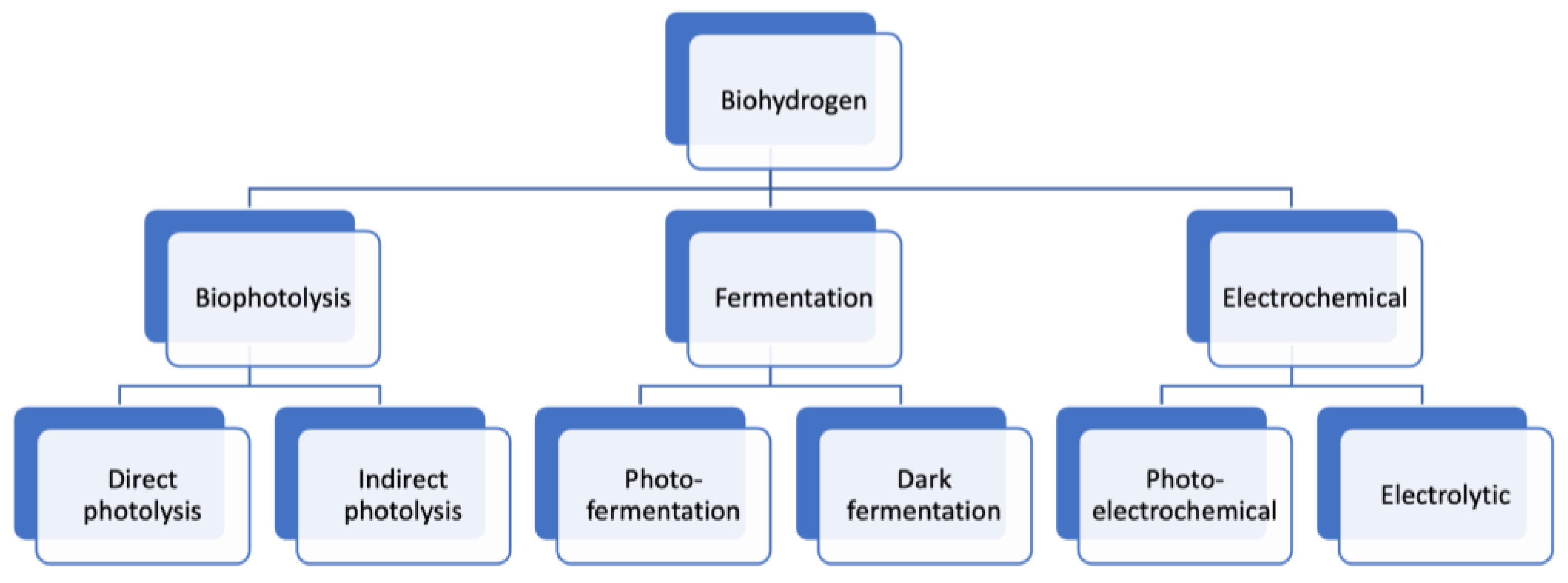
3.2. Photolytic and Biotechniques
Light is utilized to produce hydrogen by decomposing water. This technique comprises photolytic biological production and photo-electrochemical production (PEC) (Figure 5). Sunlight is used with specialized semiconductors (photo-electrochemical) to split water photo-electrochemically, while microbes and micro-algae with sunlight generate hydrogen using photolytic biological production.
Bio-photolysis: water is used as feedstock in this technology to generate hydrogen using photonic energy. Bio-photolysis is characterized by its ability to generate hydrogen using water in moderate environments featuring modest pressures and temperatures. Furthermore, this technology is proven at a laboratory scale. Bio-photolysis is categorized into two categories: direct and indirect. In direct bio-photolysis, the water is used as a substrate in the presence of light and micro-algae, such as green algae and cyanobacteria, under anaerobic circumstances to produce oxygen and hydrogen [58]. The overall reaction of bio-photolysis is expressed as [59]:
The disadvantages of direct bio-photolysis are its low performance of hydrogen generation, which is sensitive to oxygen, and its high need for light intensity. In addition, the need for enormous cultivation of algae to entrap sufficient sunlight to supply enough energy is a barrier. Moreover, the concentration and preparation of cell biomass, photosynthetic capacity rations, and respiration are viewed as challenges [60].
Indirect photolysis comprises two phases: photosynthesis and dark fermentation. In the first phase, photosynthesis is used for carbon fixation, which aims to convert the inorganic carbon into an organic compound (carbohydrate) in an open tank. In the second phase, the carbohydrate is transformed into hydrogen, carbon dioxide, and acetic acid via dark fermentation or combined photo-fermentation and dark fermentation. The overall reaction of the indirect photolysis is [59]:
The acetic acid is converted into hydrogen and carbon dioxide using light and under anaerobic conditions. Photosynthesis is characterized by a high hydrogen yield of 0.38 kJ/L/h, and the photochemical performance is 10% reached from full solar irradiance [61,62]. The ability to fix nitrogen from the atmosphere is one of the main benefits of this technique, besides the unnecessary separation of hydrogen and oxygen. However, the disadvantage is the high percentage of O2 in the gas mixture. Many micro-algae were assessed to test their ability to generate hydrogen by using crude glycerol as a cheap source of exogenous carbon to evolve a concurrent lipide and hydrogen generation process [63]. All micro-algae amassed large lipid quantities of up to 20%, but an important quantity of hydrogen is generated by Chlorella sp. under anaerobic circumstances. The integration of biohydrogen with the generation of lipids by oleaginous micro-algae could be a promising technology for the long-term feasibility of biofuel generation utilizing micro-algae. The biohydrogen generated by direct bio-photolysis ranges from 0.015 to 1.084 mmol/L.h and by indirect ranges between 0.35 to 10.26 mmol/L.h, determined by the culture circumstance, microorganism used, and feedstocks.
Dark fermentation (DF): this technology is among the biohydrogen production (BHP) technologies used to generate hydrogen, and it does not require light [64]. It transforms organic matter into carbon dioxide, hydrogen, and non-gaseous products under anaerobic or anoxic circumstances. The principle of the DF process is based on the use of carbohydrate-rich biomass with pure or mixed bacteria, such as organic acids and ethanol, under suitable conditions to generate hydrogen in a gas state and some organics products in a liquid state. According to [65], biomass rich in sugars and carbohydrates is considered to be the most appropriate feedstock for biohydrogen generation through DF. The overall reaction of dark fermentation is [66]:
This technology is considered to be favorable and propitious for biohydrogen generation since it converts the waste and residual biomass to clean energy instead of throwing it away and polluting the environment [66,67]. DF is characterized by a high hydrogen evolution rate, which is higher than that of other BHP technologies. Otherwise, the yield of H2 per substrate consumed is low. Also, the high production of carbon-rich metabolites and CO2 presents another drawback of this technology that should be treated by eliminating CO2 or detaching it from H2 and by converting it to other substances like methane (CH4) [68,69].
The main microorganisms used in DF for different substrates and the biohydrogen yield are presented in Table 1.
Photo-fermentation: this photosynthesis process is used to convert organic acids into hydrogen and CO2 in the presence of anaerobic bacteria strains like Rhodopseudomonas and Rhodobacter [80]. The operational process is based on the decrease of molecular nitrogen due to the presence of nitrogenase (an enzyme produced by bacteria) that loses a proton to hydrogen without the formation of oxygen. The overall reaction of this technology is formulated as [81]:
The advantages of this technology refer to the use of clean solar energy and the conversion of organic waste into hydrogen. On the other hand, this technology is complex, comprising biological, chemical, and physical procedures that depend on many factors that affect the output of hydrogen generation, such as medium type, microorganism type, photo-fermenter design, and light intensity [82]. Also, the drawback of this technology refers to the low growth rate of anoxygenic that leads to decreases in its efficiency, which is two orders of magnitude lower than that of dark fermentation. Moreover, photo-fermentation entails a bigger reactor than dark fermentation for the same amount of hydrogen generation amount. The combination of photo-fermentation and dark fermentation in two-stage processes leads to a rise in the hydrogen output [83]. Photo-fermentation is viewed as a better technique to generate biohydrogen compared to dark fermentation due to the higher hydrogen content (up to 58.90%) and the performance in energy conversion (10.12%) [84]. Photo-fermentation also has better performance in hydrogen generation, with a maximum hydrogen generation of 141.42 mL (g TS)−1, compared to 36.08 mL (g TS)−1 for dark fermentation. Therefore, the photo-fermentation could be considered to be a good option for biohydrogen generation. However, photo-fermentation has lower performance in sunlight transformation and biohydrogen generation compared to bio-photolysis.
Microbial electrolysis cells (MECs): this technology is used to generate hydrogen from organic material using electrochemical devices. This technology is based on the microbial oxidization of organic material to form CO2, electrons, and protons that are minimized to form hydrogen gas. The overall reaction of MECS is expressed as [85]:
The reactions occur in a reactor called a microbial electrolysis cell (MEC), and the microorganisms used are termed electricigens and act as biocatalysts. The biocatalysts are used to boost voltage performance and generation rate and to minimize the activation overpotential of a certain redox reaction [86]. Some microbes can create a biofilm on the anode surface that can transform the chemical energy into electrical energy. The generated electrical energy is used to generate beneficial output on the cathode, like H2 and CH4 [87]. This technology can generate a significant amount of biohydrogen with less environmental impact.
The use of a photobioanode, which is based on the integration of bio and solar energy on the same electrode, has been investigated in this technology. Results revealed that the photobioanode with two edges—biocarbon material and photocatalyst—forms a biofilm, resulting in enhanced extracellular electron transport and boosted exoelectrogens [88]. In addition, the use of metal-free carbon film based on CeO2-rGO as a photobioanode was tested, and a hydrogen evolution rate of 5 m3/m3/d was achieved when treating wastewater [89].
Photocatalytic: in this technology, the water splitting into hydrogen is powered by solar energy with the aid of the four-electron or two-electron method. The advantages of this technology are the fewer environmental effects without the need for energy surplus, the cost, and the large scale of hydrogen generation. The drawback of this technology is the use of expensive noble metals, which are used as efficient redox-co-catalysts owing to their high physico–chemical aspects, excellent catalytic activities, and electrical features [90]. Contrastingly, non-noble metal photocatalysts are regarded as propitious options for water decomposition thanks to their good performance, good stability, and low price. The good stability of non-noble metals avoids deactivation under some circumstances, making it convenient for transforming wastewater into hydrogen. An overview of the non-noble metal catalysts used in photocatalytic H2 evolution is presented in Table 2. Many strategies have been mentioned in the literature to promote the photocatalytic H2 generation from water splitting, such as dye-sensitization, raising the contact area and the intensity of the interconnection, ion co-doping, metalloid doping, building ore-shell structures, building ternary systems, and supervising the morphology of the catalysts [91].
3.3. Thermal Technique
Hydrogen is released from materials and organic materials using heat and chemical reactions. The organic material could be fossil fuels such as natural gas, and the material is water, and, in this case, the process is called thermochemical. The thermal technique involves natural gas reformation, biomass, coal gasification, and thermochemical generation. The methods followed by this technique are steam reformation, biomass gasification, and partial oxidation.
Steam reformation (SR): this is among the most widely used and the cheapest technologies to generate hydrogen [103]. Its features emerge from the low generation and operational cost and the high operational performance. The most common feedstocks used are methane sources like natural gases and hydrocarbons [104]. Methanol, ethanol, and glycerol could be used in this technology. Methanol has many benefits related to attainability and accessibility, vacancy of C–C bonds in its chemical structure, a large ratio of hydrogen to carbon, cheapness and safety, and moderate operating circumstances for its catalytic conversion into hydrogen. Moreover, methanol could be supplied from renewable energy resources. Ethanol is viewed as more promising because one molecule of ethanol can generate six moles of hydrogen during steam reformation compared to three moles of hydrogen generated by methanol–steam reformation. Ethanol can be generated from agricultural feedstocks and lignocellulose. Glycerol is generated from the biodiesel industry and alcohol and vegetable oil through transesterification reaction as a byproduct. The main feature of glycerol is its availability, in which one ton of biodiesel generation transesterification of edible or non-edible oil could generate 100 kg of glycerol. This process is endothermic and requires high temperature and pressure to burn the used raw material. It is performed through three phases. The overall reaction is presented as [105]:
It begins by reforming the hydrocarbon raw material with steam under high pressure (3–25 bar) and high-temperature steam (700–1000 °C) and injecting them into a catalyst reactor to obtain a mix of carbon monoxide and hydrogen (syngas) with a small quantity of CO2. The second phase, named the “water–gas shift reaction”, aims to generate more hydrogen by reacting the carbon monoxide with water to generate carbon dioxide and hydrogen using a catalytic. The last phase strives to purify the hydrogen by removing the carbon dioxide and other impurities from the gas stream. Many processes can be used in this phase, such as membrane or pressure swing adsorption. Despite the benefits of SR, it has many drawbacks attributable to the thermodynamics reactions and reactant features [106,107], such as the high generation cost and the high power, tough reaction circumstances, and low reaction performance and operation constancy. These drawbacks are due to the high stability of methane that requires high energy consumption and extra tools to ensure the high temperature and pressure required to activate it. Also, the cost and the reachability of the used noble metals catalysts restrain their use. In addition, SMR releases greenhouse gas that affects the environment and raises the cost of SR to handle these emissions. The catalyst used in steam reformation should have special properties, like high catalytic activity, good heat exchange, excellent thermal stability, accepted lifespan, low pressure decrease, and high mechanical stability. Developing cheap catalysts with properties that meet the requirement of steam reformation catalysts is crucial mainly in activating methane at low temperatures, reaching the equilibrium values over a short time, and protecting from deactivation parameters such as preferential oxidation and carbon formation [108]. The most common catalyst used in SR is Ni-based catalysts, owing to their low price and high catalytic activity. However, Ni-based catalysts suffer from coking and sintering. Many studies have been carried out to solve these issues by developing new agents, adjusting the structures of supported Ni catalysts, building self-supported Ni-based catalysts, and searching for Ni-based solid solution catalysts [109]. Some non-noble metals have a high catalytic activity compared to nickel, such as MoC2/Al2O3, which achieved better CH4 transformation compared to Ni/Al2O3 under low-temperature conditions [110]. Non-noble metal catalysts have serious issues that should be addressed, such as carbon deposition, aggregation caused by high temperature, and easiness of deactivation [111]. Noble metal catalysts, such as Ru, Ir, Rh, and Pd, have been used as catalysts in SR owing to their excellent catalytic activity and durability. However, their high cost and some issues related to aggregation and carbon deposition for some noble metals limit their uses. Many studies have been conducted to enhance the performance of noble metals while minimizing their loading quantity. Rh showed excellent catalytic activity in the conversion of CH4. A study has been conducted on the deposition of CeO2 on Rh, and results showed that Rh/CeO2 achieves the highest methane transformation compared to other noble metals [112]. The addition of CeO2 to Pt/Al2O3 enhances its efficiency in converting the CH4 [113], and the addition of 12 wt.% La2O3 to Pt/Al2O3 enhances the catalytic activity and minimizes the particle size of Pt [114].
Dry reformation (DR) is one of the new technologies that has been developed to overcome the different disadvantages of SR by improving the process of methane transformation. The chemical reaction of DR technology is presented by [93]:
The advantage of DR comes from its ability to convert the greenhouse gases CH4 and CO2, using them as oxidants, into syngas, resulting in a decrease in their emissions. It is used in processes that demand a high portion of CO in the synthesis gas. The components H2 and CO of syngas might be used to generate chemical fuels, mainly H2. It has the same thermodynamics as steam reformation. Dry reformation of methane (DRM) is viewed as a promising candidate for energy storage. For instance, DRM powered with concentrated solar energy could empower the transformation of solar energy with lower energy density into chemical energy with bigger energy density for steady and sustainable exploitation [115]. Many studies have been conducted on the thermochemical storage performance of DRM power by solar energy, which is defined as the fraction of chemical energy generated to input solar energy. A thermochemical efficiency of 19.7% was obtained by DRM reaction in a tubular and semi-cavity reactor powered by a solar dish system [116]. Moreover, the DRM reaction in a foam reactor heated by highly concentrated solar radiation achieved a thermochemical efficiency of 45.58% at c.a. 600 °C [117]. However, DR has many disadvantages attributed to a larger energy consumption that renders its application at an industrial scale unserviceable/ineffective, a higher tendency to coke (carbon with a few impurities) forming, and low fineness of syngas. The carbon formation can paralyze the operating catalyst that is used to decrease energy consumption. Two solutions could be used to reduce the coke deposition, either by increasing the temperature above 1000 °C or by adding oxygen to the feed by changing the catalysts with rare earth metals. The catalysts used in dry reformation could be noble metals (Ru, Pt, Rh, and Pd) and non-noble metals (Co, Ni, and Fe). The main advantages of noble metal catalysts derive from their excellent catalytic activity and high protection against coke deposition. According to a study [118] on the efficacity of different noble metal catalysts (Ir, Rh, Pd, Ru, Pt at 5 wt.%), Rh showed the highest catalytic activity and durability. However, their high cost is considered to be the main limitation to their use. Therefore, many studies have focused on the use of non-noble metal catalysts, mainly nickel. The authors in [119] conducted a review of the active metals dispersed over different support systems used in DRM reactions. The catalytic activity of Ni/Sab-15 [120], Ni/A12O3 [121], and Ni-MgO-Al2O3 [122] on the CH4 and CO2 conversions has been examined and showed good results. Results also showed that the rise of Ni loading led to an improvement in the CH4 and CO2 conversions [122]. A novel adapted process based on using Ni as bifunctional materials for carbon capture and methane dry reformation has been developed [123]. The process was based on using NiO-impregnated CaO material and CaO-NiO composition, and the results showed a good performance. Moreover, results pointed out that NiO-doped sodium zirconate ceramics are excellent materials for CH4 dry reformation and CO2 capture. On the other hand, the main issue with Ni catalysts is the apparent carbon deposition [124].
Performing a DRM reaction with solar energy could enable a high conversion of CH4 with a high energy storage efficiency and a high reaction temperature obtained from high solar concentration ratios. The use of a selective membrane, such as an oxygen permeation membrane reactor and three-side membrane reactor, could boost the conversion rate of a chemical reaction [125,126], as well as its potential to minimize CO2 emission owing to the smaller heat requirement and purer outcome steam from the reactor [127].
Partial oxidation (PO) is an exothermic reaction that takes place when the methane or hydrocarbons react with a finite amount of oxygen to generate a syngas stream, a small amount of carbon dioxide, and other compounds. The chemical reaction of partial oxidation is [128]:
The reaction cannot be achieved to compose carbon owing to the insufficiency of oxygen. The interest in this technology is assigned to its rapidness, which is quicker than steam reformation, and its need for a smaller reactor. Also, this method is characterized by a high conversion of methane with an excellent specificity of hydrogen and high space velocities (flow rate of the reactants/the reactor volume) of the catalyst [129]. PO has not been commercialized owing to some issues related to small drops in CO selectivity due to the overoxidation that leads to increased local temperature at the catalyst surface and conduct to deactivate the catalyst due to its sintering and carbon deposition. The catalysts used in the partial oxidation of methane (POM) are noble metals, perovskite oxides, and transition metals (Fe, Ni, and CO) [130]. The transition metals are characterized by a stimulant catalyst element for POM, and the species metal has an important contribution to the methane transformation processes. The use of Ni-supported catalysts can foster the generation of syngas due to the metallic nickel and the complete combustion of methane due to NI species with an oxidation number bigger than 2. Perovskite-cased catalyst materials proved their high catalytic activity, their potentiality in constraining themselves from carbon degradation, and their steadiness. Also, the perovskite catalyst can minimize the sill/starting value required to produce the carbon deposition. In addition, the reaction of oxygen species atop the perovskite that reacts with the carbon deposition could avoid the carbon deposition. The partial oxidation of ethanol has many benefits compared with the other thermal technologies, such as quick start-up, simple functioning without the need for an external heat source, and short reaction time [131,132]. It has been demonstrated that the combustion of porous media could be enhanced owing to its larger heat transfer performance, larger flame temperature, and speedy flame [133,134]. Moreover, the enhancement of hydrogen generation could be achieved through a larger flammability limit using super-adiabatic combustion through porous media combustion [135]. Pd-based and Pt-based catalysts can be used in POM for hydrogen generation. The Pd-based catalysts require preheating to drive POM, and the Pt-based catalysts can drive the POM with a cold start [136].
Autothermal reformation (ATR) integrates two technologies—steam reformation and fuel oxidation—in one consolidated reactor that comprises a combustion area and a catalyst bed in a refractory-lined pressure shell. In this process, the exothermic reaction of fuel oxidation provides the requested heat for the endothermic reaction of steam reformation. The feedstock used in this process can be liquefied petroleum gas, naphtha, natural gas, Fischer–Tropsch tail-gas, pre-reformed gas, or refinery off gas. This technique is performed under pressures of between 30 and 50 bar, temperatures between 950 and 1050 °C, an oxygen-to-carbon molar rate of 0.6–1, and a steam-to-carbon molar rate of 0.5–1.5 [137]. The chemical reaction of ATR is formulated as [138]:
The operational process of this technology starts with the desulfurization of the feed gas to remove the sulfur, which should be preheated and pre-reformed before injecting it into the ATR reactor using the referenced proprietary heater. After that, syngas is produced by reacting the feed gas with oxygen and steam. Then, the generated syngas is injected again into the same reactor for more reformation to attain high output, achieving thermodynamic equilibrium. In the last stage, the syngas streams into a gas boiler, which is used to cool down the syngas and produce high-pressure steam. The syngas can be used in several applications, such as generating hydrogen by separating the components of the syngas and using it as raw material for other synthesis processes (Fischer–Tropsch). Also, the high-pressure steam can be used for power production. ATR is common for smaller-scale hydrogen production, quicker power-up and reaction time than SR, higher output H2 generation than POX, and lower operational cost and energy requirements [139]. The issue of this process is the choice of the catalyst that should serve the SR and the fuel oxidation and correspondence to the used fuel. Also, for high-generation capacities, this technology becomes cost-effective due to the large investment requested for an oxygen generation station [139].
Noble metal-based catalysts, like Rh/Al2O3, can generate a high amount of hydrogen in ATR, but their use is limited due to their high cost [140]. A non-precious-metal catalyst could be used in the ATR of ethanol. A nickel-based catalyst is a good candidate, but it generates low hydrogen at low temperatures. Moreover, the deactivation of the catalyst is induced by rubbishing and carbon deposition on the surface of the catalyst. The enhancement of the catalytic activity and stability of Ni-based catalysts could be achieved by adding some metals like Co, Cu, or Mo or utilizing different supports like CeO2, La2O3, and Y2O3 [141,142]. Moreover, iron is known as an active element in the water–gas shift reactions. It can lessen carbon deposition and raise selectivity to carbon dioxide, which is pivotal for the hydrogen-opulent reformat gases used as fuels for application in fuel cells [143]. Moreover, iron has identical electronic properties to nickel. Therefore, it could enhance the nickel-based catalysts. Ammonia decomposition is used to generate hydrogen by operating an autothermal microchannel reactor. The effects of different operating conditions on the performance of the reactor have been studied [144]. Results have revealed that the best functional circumstances were achieved with a flow rate of ammonia of 0.4 NLPM, with a fuel-rich calculation equable to a fuel equivalence rate of 1.2, and a combustible feed flow velocity of 0.8 NLPM.
Plasma reformation: plasma is an ionized gas produced in several ways, such as shocks, flames, and electric discharge. It is distinguished by high electrical conductivity. Plasma has the potential to supply high temperatures appropriate for thermal decomposition, decreasing activation energy via vibrational excitation-based reaction passage, electron collision-created cleavage, and ions and radicals adequate for utilization in catalytic reactions [145]. It has been experienced to be used in the generation of hydrogen through the reformation process due to its high energy density. The whole reformation reaction is similar to traditional reformation. The only difference is that the plasma is used to generate the energy and the free radicals required to run the reformation processes. In this technology, a catalyst is not required since plasma acts as the catalyst due to the high energy density. The main benefit of this method is low power consumption compared to steam reformation and electrolysis and operation at low operating temperatures. In addition, the generation cost is low, and the steam/heat output might be used for other procedures [146]. According to [147], increasing the temperature by adding a heater and raising the input voltage of the coil leads to a rise in the hydrogen generation rate. The drawbacks of plasma reformation are the need for electrical energy and the hardness of the high-pressure process, which negatively affect the lifetime of the electrode because it raises electrode corrosion by the reduction of arc mobility [148]. Plasma can be classified into thermal plasma and non-thermal plasma based on the method of deposition of energy into the gas stream. The main benefits of non-thermal plasma reformation compared to thermal technology are high yield, instantaneous boot time, and lower energy cost. The gliding arc is based on a transitional non-equilibrium plasma, beginning as thermal arc plasma. The gas flow or magnetic field extends it, and it is snuffed out after it converts to non-thermal arc plasma. It is considered to be a non-thermal arc plasma due to the temperature of converted gas in the scope, which varies between 2200 and 2500 K, and it is enclosed by the temperature of cold plasma (300 K) and thermal plasma (more than 10,000 K) [149]. A non-thermal arc has the potential to generate an efficient plasma with high effectivity and good astucity. It has been proved that the use of a gliding arc discharge reactor with a vortex flow configuration can achieve the best reformation outcomes in the matter of fuel transformation and low-priced energy needed for syngas generation [150]. The effect of different factors such as voltage, temperature, waveform, and feeding rate on methanol transformation plasma–catalytic methanol–steam reformation under electric discharge has been examined [151]. Results have revealed that the rise of frequency and discharge voltage leads to improved methanol conversion controlled by electric discharge. The main benefit of electric discharge is the amount of energy supplied, which is enough to break the chemical bonds of methanol and steam. In addition, a square waveform has been proven to be more efficient in methanol conversion compared to a sine waveform. Also, a rise in absorption intensities of reactants on the active surface on the catalyst surface is achieved by a strong electric field.
Pyrolysis is considered among the thermochemical technologies that convert biomass into hydrogen. Pyrolysis is a well-known route for hydrogen production, in which hydrogen-containing compounds such as hydrocarbons are the only reactants. In fact, these compounds are decomposed by heating in the absence of oxygen and water to achieve a high temperature (between 375 and 525 °C) in a short period. In this regard, the pyrolysis of biomass is a renewable source, and pyrolysis of methane and hydrogen sulfide is used as feedstock. The output of the reaction is a liquid mixture produced in a gaseous mixture that will then be liquified [152]. The overall reaction of pyrolysis is given by [153]:
Many factors affect the performance of generating hydrogen by pyrolysis, such as temperature, the rate of biomass heating, the catalyst type, and the time interval [154,155,156]. The high temperature and the short process time led to an increase in the hydrogen yield. Biomass pyrolysis requires low-pressure operation [157]. The feasibility of its application using several feedstock materials is considered to be its main advantage, while the requisite of a high amount of energy is the main drawback [158].
Biomass gasification is known as one of the thermochemical conversion technologies to convert organic material into synthetic gas (syngas) and a solid product labeled char in an enclosed gasifier at high pressure and temperature. Syngas is a combustible gas that contains mainly hydrogen and carbon, and it can be used as a fuel source and intermediate to generate chemical products. The char is a blend of untransformed organic portions, predominately carbon and ash. Biomass gasification is regarded as a promising technology for hydrogen-rich syngas and is characterized by high energy performance and low CO2 emissions [159]. It has been developed at a commercial scale. The feedstocks used in this technology are biomass resources, like municipal and industrial wastes, and forestry and agriculture leftovers [160]. The disadvantage of this technology is the high cost of hydrogen generation, which can reach 3.5 USD/GGE, compared with the SR technology [161,162].
Thermolysis is a thermochemical process where water is decomposed into hydrogen and oxygen using chemical reactions and, under high temperatures (500–2000 °C), heat is provided from concentrated solar power, wind energy, and waste heat from nuclear reactors. This technology is characterized by carbon-free or low-carbon emissions. Also, this technology makes a locked loop that is fed only by water to generate hydrogen and oxygen since the chemicals utilized in the operation are reused in each twirl.
The energy generated by wind farms could be used to perform an electrolysis process and generate green hydrogen. The wind-driven hydrogen generation could enhance the overall resource use of wind energy. The working principle is based on the use of energy generated by wind to generate hydrogen in electrolytic cells and then to separate and purify the produced hydrogen to compress and store it. Many studies have been performed to evaluate hydrogen generation using on and offshore wind in many countries [163,164,165]. A study has been conducted by [166] to assess the generation of hydrogen using wind farms in Pakistan. Findings have indicated that the generation of hydrogen using wind energy is commercially feasible in many cities in Pakistan, and the hydrogen generated could be used to fuel many forms of transportation.
Solar energy is also used to feed electrolysis to generate green hydrogen. Two technologies use solar energy to produce green hydrogen: photovoltaic electrolysis and concentrated PV electrolysis. Many solar-driven hydrogen generation projects have been erected to generate hydrogen using PV panels. In the past, the use of this technology was disappointing due to the low performance of solar to hydrogen (2–6%) and the high capital cost (40 USD/kg of hydrogen) [167,168]. Recently, many studies have been conducted to enhance efficiency and decrease the capital cost of this technology. A rise of solar hydrogen efficiency to 12.4% could be attained by matching the maximum power output voltage of the PV system with the operating voltage of the electrolyzer [169]. Also, an integration of multi-junction PV with electrolysis could achieve a high efficiency, around 16% [170]. Moreover, a study showed that the optimization of hydrogen generation could be attained using a DC/DC buck transformer with an MPPT and by controlling the water flux inserted in the electrolysis [171]. Using a DC/DC buck transformer can enhance the acclimation between the electrolysis and the PV generator, and the control of water flux can enhance hydrogen generation.
Nuclear energy-driven hydrogen generation technology is viewed as a promising and attractive way to generate green hydrogen. Nuclear energy is more advantageous than renewable energy resources, which have many drawbacks related to density, magnitude, goodness, and reliability [172]. Nuclear energy can produce hydrogen energy by means of high-temperature thermochemical processes or using temperature steam electrolysis. The working principle of this technique is based on the use of high heat generated by the reactor to split the water into hydrogen and oxygen. The drawbacks of this technology are the high corrosivity caused by high temperatures that affect the materials used and some hazards caused by the extending process [173]. To achieve an effective electrochemical and thermochemical performance, high temperatures are requested and can be obtained using high-temperature reactors. Molten salt-cooled, gas-cooled, and liquid-cooled reactors are some examples of reactors that can be used to generate hydrogen. The most economical reactor to generate hydrogen is the high-temperature gas-cooled reactor (HTGR) [174]. The first high-temperature gas-cooled (HTGR) reactor was built in Japan by the Japanese Atomic Energy Agency (JAEA). The development and commercialization of generating hydrogen with nuclear energy using HTGR is attributed to the JAEA. Moreover, the issue of nuclear waste with high radioactivity levels is solved by the development of accelerator-driven systems through the turning of long-lived fission products (LLFP) and MA into less dangerous nuclides diminished lives [174].
4. Comparison of the Technologies Used to Generate Hydrogen
A comparison of the technologies presented in the current paper and used to generate hydrogen in terms of efficiency, advantages, and drawbacks is displayed in Table 3. It can be noticed that the reformation technologies have the highest efficiencies, but they are characterized by high energy consumption and high greenhouse gas emissions. Steam reformation and plasma reformation could attain an efficiency of 85%, compared to 75% by partial oxidation and autothermal and 50% by biomass gasification.
In biological processes, micro-algae and bacteria are used to generate hydrogen by means of biological reactions and using either organic matter or sunlight. This process gains more attention owing to the large and easy attainability of feedstock material, low to net-zero carbon emission, and economic competitiveness. In addition, this process might use wastewater since bacteria and algae could be expanded/developed in wastewater. However, the methods used in this process are characterized by low yield/efficiency and require more research [175].
Water electrolysis technologies are considered to be clean and environmentally friendly if combined with renewable energy resources. PEM and alkaline are used under low temperatures, while solid oxide electrolyzers (SOE) are used under high temperatures. PEM has the advantages of hydrogen gas purity and high current densities compared to alkaline electrolysis. Anion exchange membrane (AEM) and PEM electrolysis have analogous assemblies, while the membrane in AEM transport anions (OH–) is a substitute for proton (H+). AEM and alkaline use the same process in the electrodes. AEM is cheaper than PEM due to the use of cheaper membrane transport anions, and AEM does not use noble metal catalysts. A high-purity hydrogen could be achieved using AEM at high pressure compared to an alkaline electrolyzer. PEM electrolysis could achieve a higher efficiency of 70% compared to AEM, alkaline, and SOE, which have an efficiency of 60%. Seawater electrolysis is viewed as a promising method to generate clean hydrogen without requiring a high demand for freshwater since it uses seawater and can achieve an efficiency of 72%. However, the corrosion of the positive electrolyte by the negatively charged chloride that exists in seawater leads to court the lifespan of the system. This drawback can be overcome using layers loaded in negative charges to coat the anode; therefore, they can repel the chloride and cease the degradation of the essential metal.

Table 3.
Comparison of the technologies used to generate hydrogen.
| Technology | Efficiency | Advantages | Drawbacks | Maturity | Reference |
|---|---|---|---|---|---|
| Alkaline electrolyzer | 50–78% | Long-term stability, cost-effective, low cost, mature technology, non-noble catalyst | Low current densities, low operational pressure, corrosive liquid electrolyte, crossover of gases | Commercial | [23] |
| PEM electrolyzer | 50–83% | High current densities and voltage efficiency, high gas purity, rapid system response | High cost of components, acidic corrosive environment, low durability | Commercial | [23] |
| Solid oxide electrolysis cells | 89% (lab) | No electrode corrosion, since it performs with high temperatures, so no need for expensive catalysts and better ability to tolerate the presence of impurities, negligible pollution | Bulky design, durability issues, high cost, and complex fabrication | Medium-term | [176] |
| Anion exchange membrane | 57–59% | Chloride resistance, oxidation resistance, alkali resistance, and diffusion and dialysis to recover acid, regeneration is not required, high-purity hydrogen | Low power performance, low ionic conductivity, important catalyst loading, and moderate-range membrane stability with significant ohmic resistance loss | Commercial | [43] |
| Plasma electrolysis | - | Generate more hydrogen using less energy consumption compared to hydrocarbon electrolysis | [177] | ||
| Seawater electrolysis | 72% | Mitigation of freshwater consumption since seawater is a plentiful resource | Capital costs of the water purification equipment and the environmental problem arising from the need to dispose of the residual salts removed during desalinization | R&D | [178] |
| Photolysis | 10–11% | CO2 neutral, O2 generation | High needs of light intensity, low performance, expensive | Long term | [179] |
| Dark fermentation | 60–80% | Light is not mandatory required, and many substrates can be used as carbon source | Low yield of H2 per substrate consumed—concomitant production of carbon-rich metabolites (i.e., organic acids, alcohols) and CO2, big reactor needed | Long term | [180] |
| Photo-fermentation | 10% | Possibility of using different organic biomass—oxygen inhibition effects on hydrogen generation is removed since photosynthetic bacteria do not have PSII | Photochemical performance is low, and nitrogenase activity is restrained due to the existence of oxygen Low efficiency | Long term | [181] |
| Microbial electrolysis cells | 78% | Possibility to work at high pressure with low energy consumption, ecofriendly electrolyte, low-cost material, self-sustained and self-assembled electrocatalyst, oxidation of organic compounds | Hydrogen can be consumed at the bioanode, bioanodes do not accept high temperatures and high substrate concentrations and are very sensitive to slightly acidic pH | Long term | [182] |
| Steam reformation | 70–85% | No oxygen required, lowest process temperature, good H2/CO ratio | Highest greenhouse gas emission | Commercial | [183] |
| Dry reformation | Possibility to use CO2 | Large energy consumption, higher tendency to coke forming, forming and low fineness of syngas | - | [93] | |
| Partial oxidation | 60–75% | Catalyst is not required, low methane slip | Very high processing temperatures, Low H2/CO, generation of heavy oils | Commercial | [184] |
| Autothermal reformation | 60–75% | Low methane slip, requires less temperature than POX, existing infrastructure, mature | Needs air or oxygen, generation of GHG | Near term | [185] |
| Plasma reformation | 9–85% | No need for thermal activation, quick reaction start-up, long durability, reliable, small reaction volume | Requires electrical energy | Long term | [148] |
| Biomass gasification | 35–50% | CO2-neutral-decrease the amount of energy sources | Requires a large amount of land and very inefficient | Commercial | [186] |
| Pyrolysis | 35–50% | Possibility of using several cheap feedstock materials | Require high amount of energy, seasonal disponibility, Tar formulation | Near term | [187] |
5. Barriers to Hydrogen Generation
Hydrogen energy is viewed as one of the most favorable alternative fuels to achieve sustainable mass transport. It has the potential to decarbonize transport since it can be exploited in fuel cells to power vehicles by converting H2 into electricity without emitting harmful pollutants and greenhouse gases. A hydrogen vehicle emits less than 15 tons if generated by renewable electrolysis compared to 40 and 45 metric tons of a diesel vehicle [188]. Hydrogen fuel can power airplanes, domestic heating, steel production, heavy commercial vehicles, and long-haul freight vehicles. In addition, hydrogen could be an effective part of the transition to more sustainable energy. It can be used as energy storage for intermittent renewable energy, in both the medium and long term, due to its very high specific energy. However, hydrogen should be stored as gas at high pressure or as a liquid at cryogenic temperature since it has a very low volumetric density. Moreover, hydrogen can play a crucial role in the long-distance transport and trade of energy.
Despite all the advantages of hydrogen energy, its generation faces many challenges that should be addressed to boost the evolution of the hydrogen market in the coming years. These challenges are presented below.
- -
- There are many existing technologies for hydrogen generation. Some of these technologies are cheap but pollute the environment, and others are expensive and clean. Hydrogen producers face an important issue in choosing the best technology and the source of energy used to perform the generation process.
- -
- Hydrogen storage is considered to be a significant barrier since high space is required to stock hydrogen owing to its low density, resulting in increasing hazardous accidents due to the high flammability of hydrogen. Also, energy efficiency is a significant issue for all hydrogen storage technologies. The round-trip efficiency of hydrogen storage is 32% compared to 95% of battery storage [189,190]. Moreover, the cost of hydrogen storage is expensive compared to the storage of petroleum fuels. The capital cost of underground and aboveground hydrogen storage compared to battery storage is shown in Table 4. It is observable that the charging and discharging cost of hydrogen storage is higher than that of battery storage, but the discharging cost of hydrogen storage is lower than that of battery storage.
- -
- A hydrogen-fueled vehicle might be less preferable since less space will be available for commuters due to the high space of hydrogen storage [191]. Also, the mileage that the vehicle can travel before recharge presents a barrier since the vehicles require a big storage capacity, resulting in bigger space in the vehicle. This issue could be solved through electric vehicles using fuel cell batteries, which have some issues related to the cost and the resources that are not renewable [192]. Furthermore, the installation of recharging stations required for hydrogen-fueled vehicles causes a problem since investors will not invest in the installation if they are not sure that people will buy and use hydrogen vehicles [193]. Another issue related to the long process of the design and installation of infrastructure is the road networks and pipelines required for fuel charging stations.
- -
- The expanding hydrogen market is facing the impediment of the ability of the existing technologies to meet the hydrogen demand that is projected to increase in the coming years with a competitive cost.
- -
- The use of hydrogen for transportation, electrification, and heating is less effective than direct technology since hydrogen is an energy carrier and not a primary energy source, resulting in a high conversion loss.
- -
- The carbon capture and storage (CCS) used in the generation of blue hydrogen is unproven at scale and expensive since it requires equipment, materials, and infrastructure for transportation and storage, causing an increase in the cost of the generated energy. In addition, the CO2 captured in CCS is used in enhanced oil recovery to liberate unreachable oil into the depleted oil wells, resulting in increasing CO2 emissions into the atmosphere. Also, the leakage of CO2 during transportation and at the site of underground storage causes an immediate menace to human and animal welfare, even if accident rates are very low.
- -
- The generation of hydrogen through electrolysis consumes a huge amount of water. In addition, the water used in the electrolysis process should be purified before using it. Therefore, the capital cost of hydrogen generation increases with the cost of water, purification, and transportation.
6. Economics of Hydrogen Generation
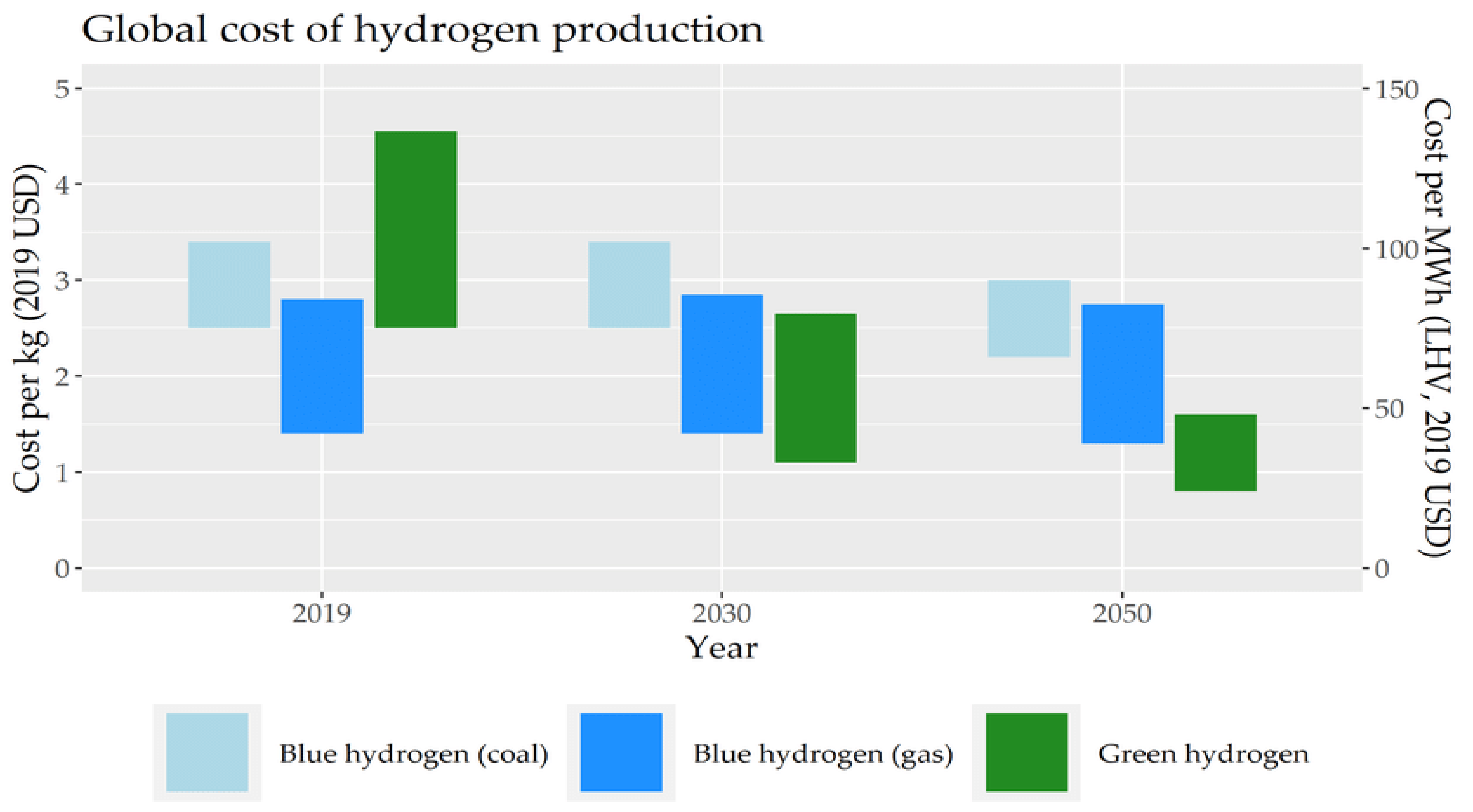
6.1. Cost of Hydrogen Based on Hydrogen Types
An analysis of the hydrogen-based energy system has been conducted [194]. The findings pointed out that the global future energy system will be established mainly on electricity and hydrogen. The cost of hydrogen relies on technologies used to generate hydrogen and the feedstock used. Among the different types of hydrogen (colors), the lowest cost of hydrogen generation is gray hydrogen, with a price range from 0.88 to 2.31 USD/kg of H2 [195]. The cost of blue hydrogen is higher owing to the necessity to use devices/systems to capture and store carbon, and it ranges between 1.32 and 3.30 USD/kg of H2 [196]. The generation cost of green hydrogen through electrolysis is the most expensive, and it ranges from 2.42 to 9.01 US USD/kg of H2 [195,196].
Figure 6 displays the cost of blue hydrogen, generated with coal and gas, and green hydrogen in 2019 and a future estimation of their costs [197]. It can be noticed that the cost of blue hydrogen generated with gas is the lowest, and the cost of green hydrogen is the highest. Blue hydrogen is 2–3 times cheaper than green hydrogen. Nevertheless, the cost of green hydrogen is projected to drop significantly, by up to 60%, to reach a minimum value of 1.5 USD/kg by 2050. Many issues affect the cost of green hydrogen, such as the renewable electricity price, operating hours, and the electrolyzer investment cost [198]. Innovation and enhanced efficiency are required to maximize the electrolyzer’s ability to reach multi-gigawatt (GW) levels. The drop in electricity price and the investment cost of electrolysis facilities are fundamental to producing a competitive green hydrogen.
6.2. Cost of Hydrogen Generated Based on the Technologies Used
Currently, the most predominately used and economical technology for hydrogen generation is the steam reformation of methane. Around half of all global hydrogen is generated using steam reformation, with a generation cost of 7 USD/GJ. Partial oxidation of hydrogen showed a competitive price for hydrogen generation. Nevertheless, a carbon capture and storage system should be integrated to minimize the greenhouse gases generated by thermochemical technologies, and in this case, a rise in hydrogen price by 25–30% must be considered [61].
Gasification and pyrolysis of biomass are among the thermochemical technologies used to generate hydrogen. The cost of hydrogen generation by gasification and pyrolysis is costly, about three times greater than the cost of hydrogen generated by steam reformation technology. Therefore, these technologies are generally not deemed as cost-competitive for steam reformation. The cost of hydrogen generated by gasification and pyrolysis of biomass ranges from 10 to 14 USD/GJ and from 8.9 to 15.5 USD/GJ, respectively. The generation cost depends on different factors, including the equipment, accessibility, and cost of raw materials [1].
Generating hydrogen using water electrolysis is considered to be the simplest and most efficient process without byproducts. However, the generation of hydrogen through water electrolysis is costly due to the cost of electricity needed to split the water and the cost of water. Decreasing the electricity prices and increasing the operating hours are crucial for hydrogen generation through electrolysis [199].
An economic analysis of the different hydrogen generation technologies has been carried out [200]. Results demonstrated that the most economical technology is the generation of gray hydrogen. In addition, the study indicated that alternative technologies could be economically competitive in the future. Gasification and pyrolysis have the potential to be competitive over time [201]. Also, results showed that hydrogen-generated power by solar energy is the most ecofriendly process. The main technologies to generate hydrogen by 2030 will be steam reformation of natural gas and catalyzed biomass gasification. In addition, coal gasification and electrolysis will be used to a limited extent. Hydrogen production using solar energy is arguable in a given context and is questionable but also possible. The use of solar energy will most likely rise by 2050 [1].
A comparative study of the different hydrogen generation technologies in terms of efficiency and cost has been performed [195]. Findings showed that hydrogen generation based on fossil fuels is not in phase with the transition toward a sustainable energy future. Also, the study pointed out that in the case of the generation of blue hydrogen, substantial fugitive methane emissions happen, which is not taken into consideration in most studies. Moreover, the study discussed the possibility of decreasing the cost of electrolysis in the future. The introduction of a global hydrogen market is viewed as an important key player since it would enable countries with suitable circumstances for renewable energy generation to generate hydrogen at lower costs [202].
The cost breakdown of different technologies used to generate hydrogen is displayed in Table 5. The highest investment cost is recorded for PEM electrolysis, with a value of 3163 (USD/kW), and the lowest is for the SMR technology. Steam reformation and steam reformation with CCUS have the highest operating time and the lowest energy price.
7. Conclusions
Hydrogen energy is viewed as the most available fuel worldwide and as one of the prime options for storing renewable energy. It is an energy carrier used to store and transport energy generated from other resources. Hydrogen energy is versatile. It can be generated from several types of feedstocks and using a wide variety of technologies. This paper presents an overview of the existing technologies used to generate hydrogen from fossil and non-fossil fuels. These technologies are classified into three categories: electrolytic, photolytic/biotechnique, and thermal. In electrolytic technology, electricity is used to break water into oxygen and hydrogen, and the electricity used can be from fossil fuels or renewable energy. Light energy, microbes, and micro-algae are used in photolytic and biotechniques to break water into hydrogen and oxygen. In the thermal process, energy is used to liberate hydrogen from several feedstocks, such as coal, natural gas, and biomass, which incorporate hydrogen in their molecular bodies. Also, hydrogen can be generated from feedstocks (like water) by combining heat with a closed chemical cycle. Results showed that the most mature technologies are steam reformation and biomass gasification. The actual technologies used for the generation and exploitation of hydrogen do not conform with the environmental sustainability goals. The electrolytic process could be a sustainable option if renewable energy is used; however, its cost and efficiency depend on the cost and efficiency of the renewable energy resources used. Photolytic and biotechnique methods are auspicious methods to generate hydrogen, but they are in the early stages of development, and they are not feasible on a large scale. Gasification and thermochemical technologies are economically feasible and competitive compared to reformation methods.
The different barriers affecting the growth of the hydrogen energy market are highlighted in this paper. These barriers include low efficiency, high capital cost, and high storage volume and cost. In the case of the electrolysis process using renewable energy, hydrogen generation faces more challenges related to the extra cost of renewable energy, the cost of water, its purification, and its transportation. More research studies should be addressed to overcome the different challenges and boost the growth of the hydrogen market in the coming years. The capital cost of hydrogen generation and storage should be minimized by decreasing the cost of materials and components, increasing the efficiency of the used technology, and dropping the cost of renewable energy.
Funding
This research received no external funding.
Institutional Review Board Statement
Not applicable.
Informed Consent Statement
Not applicable.
Data Availability Statement
No new data were created.
Conflicts of Interest
The authors declare no conflict of interest.
References
- Mazloomi, K.; Gomes, C. Hydrogen as an energy carrier: Prospects and challenges. Renew. Sustain. Energy Rev. 2012, 16, 3024–3033. [Google Scholar] [CrossRef]
- Stambouli, A.B.; Traversa, E. Fuel cells, an alternative to standard sources of energy. Renew. Sustain. Energy Rev. 2002, 6, 295–304. [Google Scholar] [CrossRef]
- Kochanek, E. The role of hydrogen in the visegrad group approach to energy transition. Energies 2022, 15, 7235. [Google Scholar] [CrossRef]
- Ramachandran, R.; Menon, R.K. An overview of industrial uses of hydrogen. Int. J. Hydrogen Energy 1998, 23, 593–598. [Google Scholar] [CrossRef]
- Ehteshami, S.M.M.; Chan, S. The role of hydrogen and fuel cells to store renewable energy in the future energy network–potentials and challenges. Energy Policy 2014, 73, 103–109. [Google Scholar] [CrossRef]
- Al-Fatesh, A.S.; AL-Garadi, N.Y.; Osman, A.I.; Al-Mubaddel, F.S.; Ibrahim, A.A.; Khan, W.U.; Alanazi, Y.M.; Alrashed, M.M.; Alothman, O.Y. From plastic waste pyrolysis to Fuel: Impact of process parameters and material selection on hydrogen production. Fuel 2023, 344, 128107. [Google Scholar] [CrossRef]
- Navarro, R.M.; Pena, M.; Fierro, J. Hydrogen production reactions from carbon feedstocks: Fossil fuels and biomass. Chem. Rev. 2007, 107, 3952–3991. [Google Scholar] [CrossRef] [PubMed]
- IRENA. Hydrogen, A Renewable Energy Perspective, International Energy Agency; IRENA: Abu Dhabi, United Arab Emirates, 2019. [Google Scholar]
- IEA. Global Hydrogen Review 2021, IEA, Paris. Available online: https://www.iea.org/reports/global-hydrogen-review-2021 (accessed on 20 August 2023).
- IEA. Global Hydrogen Review 2022, IEA, Paris. Available online: https://www.iea.org/reports/global-hydrogen-review-2022 (accessed on 20 August 2023).
- Nastasi, B. Hydrogen Policy, Market, and R&D Projects. In Solar Hydrogen Production; Elsevier: Amsterdam, The Netherlands, 2019; pp. 31–44. [Google Scholar]
- Arregi, A.; Amutio, M.; Lopez, G.; Bilbao, J.; Olazar, M. Evaluation of thermochemical routes for hydrogen production from biomass: A review. Energy Convers. Manag. 2018, 165, 696–719. [Google Scholar] [CrossRef]
- Zeng, K.; Zhang, D. Recent progress in alkaline water electrolysis for hydrogen production and applications. Prog. Energy Combust. Sci. 2010, 36, 307–326. [Google Scholar] [CrossRef]
- IRENA. Hydrogen from Renewable Power: Technology Outlook for the Energy Transition; International Renewable Energy Agency: Abu Dhabi, United Arab Emirates, 2018. [Google Scholar]
- Shabaker, J.W.; Dumesic, J.A. Kinetics of aqueous-phase reforming of oxygenated hydrocarbons: Pt/Al2O3 and Sn-modified Ni catalysts. Ind. Eng. Chem. Res. 2004, 43, 3105–3112. [Google Scholar] [CrossRef]
- Wang, Z.; Roberts, R.; Naterer, G.; Gabriel, K. Comparison of thermochemical, electrolytic, photoelectrolytic and photochemical solar-to-hydrogen production technologies. Int. J. Hydrogen Energy 2012, 37, 16287–16301. [Google Scholar] [CrossRef]
- Harrison, K.W.; Remick, R.; Hoskin, A.; Martin, G. Hydrogen Production: Fundamentals and Case Study Summaries; National Renewable Energy Lab. (NREL): Golden, CO, USA, 2010. [Google Scholar]
- Correa, G.; Marocco, P.; Muñoz, P.; Falagüerra, T.; Ferrero, D.; Santarelli, M. Pressurized PEM water electrolysis: Dynamic modelling focusing on the cathode side. Int. J. Hydrogen Energy 2022, 47, 4315–4327. [Google Scholar] [CrossRef]
- Chen, K.; Dong, D.; Jiang, S.P. Hydrogen Production from Water and Air through Solid Oxide Electrolysis. In Production of Hydrogen from Renewable Resources; Springer: Berlin/Heidelberg, Germany, 2015; pp. 223–248. [Google Scholar]
- Delgado, H.E.; Radomsky, R.C.; Martin, D.C.; Bartels, D.M.; Rumbach, P.; Go, D.B. Effect of competing oxidizing reactions and transport limitation on the faradaic efficiency in plasma electrolysis. J. Electrochem. Soc. 2019, 166, E181. [Google Scholar] [CrossRef]
- Ursua, A.; Gandia, L.M.; Sanchis, P. Hydrogen production from water electrolysis: Current status and future trends. Proc. IEEE 2011, 100, 410–426. [Google Scholar] [CrossRef]
- Keçebaş, A.; Kayfeci, M.; Bayat, M. Electrochemical Hydrogen Generation. In Solar Hydrogen Production; Elsevier: Amsterdam, The Netherlands, 2019; pp. 299–317. [Google Scholar]
- Carmo, M.; Fritz, D.L.; Mergel, J.; Stolten, D. A comprehensive review on PEM water electrolysis. Int. J. Hydrogen Energy 2013, 38, 4901–4934. [Google Scholar] [CrossRef]
- Lei, Q.; Wang, B.; Wang, P.; Liu, S. Hydrogen generation with acid/alkaline amphoteric water electrolysis. J. Energy Chem. 2019, 38, 162–169. [Google Scholar] [CrossRef]
- Wang, S.; Lu, A.; Zhong, C.-J. Hydrogen production from water electrolysis: Role of catalysts. Nano Converg. 2021, 8, 4. [Google Scholar] [CrossRef] [PubMed]
- Jang, D.; Choi, W.; Cho, H.-S.; Cho, W.C.; Kim, C.H.; Kang, S. Numerical modeling and analysis of the temperature effect on the performance of an alkaline water electrolysis system. J. Power Sources 2021, 506, 230106. [Google Scholar] [CrossRef]
- Ďurovič, M.; Hnát, J.; Strečková, M.; Bouzek, K. Efficient cathode for the hydrogen evolution reaction in alkaline membrane water electrolysis based on NiCoP embedded in carbon fibres. J. Power Sources 2023, 556, 232506. [Google Scholar] [CrossRef]
- Jang, D.; Cho, H.-S.; Kang, S. Numerical modeling and analysis of the effect of pressure on the performance of an alkaline water electrolysis system. Appl. Energy 2021, 287, 116554. [Google Scholar] [CrossRef]
- Zhang, B.; Fan, L.; Ambre, R.B.; Liu, T.; Meng, Q.; Timmer, B.J.; Sun, L. Advancing proton exchange membrane electrolyzers with molecular catalysts. Joule 2020, 4, 1408–1444. [Google Scholar] [CrossRef]
- Hayashi, T.; Bonnet-Mercier, N.; Yamaguchi, A.; Suetsugu, K.; Nakamura, R. Electrochemical characterization of manganese oxides as a water oxidation catalyst in proton exchange membrane electrolysers. R. Soc. Open Sci. 2019, 6, 190122. [Google Scholar] [CrossRef] [PubMed]
- Sun, S.; Shao, Z.; Yu, H.; Li, G.; Yi, B. Investigations on degradation of the long-term proton exchange membrane water electrolysis stack. J. Power Sources 2014, 267, 515–520. [Google Scholar] [CrossRef]
- Ayers, K.E.; Renner, J.N.; Danilovic, N.; Wang, J.X.; Zhang, Y.; Maric, R.; Yu, H. Pathways to ultra-low platinum group metal catalyst loading in proton exchange membrane electrolyzers. Catal. Today 2016, 262, 121–132. [Google Scholar] [CrossRef]
- Rakousky, C.; Reimer, U.; Wippermann, K.; Carmo, M.; Lueke, W.; Stolten, D. An analysis of degradation phenomena in polymer electrolyte membrane water electrolysis. J. Power Sources 2016, 326, 120–128. [Google Scholar] [CrossRef]
- Böhm, D.; Beetz, M.; Gebauer, C.; Bernt, M.; Schroeter, J.; Kornherr, M.; Zoller, F.; Bein, T.; Fattakhova-Rohlfing, D. Highly conductive titania supported iridium oxide nanoparticles with low overall iridium density as OER catalyst for large-scale PEM electrolysis. Appl. Mater. Today 2021, 24, 101134. [Google Scholar] [CrossRef]
- Hernández-Gómez, Á.; Ramirez, V.; Guilbert, D. Investigation of PEM electrolyzer modeling: Electrical domain, efficiency, and specific energy consumption. Int. J. Hydrogen Energy 2020, 45, 14625–14639. [Google Scholar] [CrossRef]
- Diéguez, P.; Ursúa, A.; Sanchis, P.; Sopena, C.; Guelbenzu, E.; Gandía, L. Thermal performance of a commercial alkaline water electrolyzer: Experimental study and mathematical modeling. Int. J. Hydrogen Energy 2008, 33, 7338–7354. [Google Scholar] [CrossRef]
- Zahid, M.; Schefold, J.; Brisse, A. High-Temperature Water Electrolysis Using Planar Solid Oxide Fuel Cell Technology: A Review. In Hydrogen and Fuel Cells, Fundamentals, Technologies and Applications; Wiley-VCH: Weinheim, Germany, 2010; pp. 227–242. [Google Scholar]
- Seitz, M.; von Storch, H.; Nechache, A.; Bauer, D. Techno economic design of a solid oxide electrolysis system with solar thermal steam supply and thermal energy storage for the generation of renewable hydrogen. Int. J. Hydrogen Energy 2017, 42, 26192–26202. [Google Scholar] [CrossRef]
- O’brien, J.; McKellar, M.; Harvego, E.; Stoots, C. High-temperature electrolysis for large-scale hydrogen and syngas production from nuclear energy–summary of system simulation and economic analyses. Int. J. Hydrogen Energy 2010, 35, 4808–4819. [Google Scholar] [CrossRef]
- Eguchi, K.; Hatagishi, T.; Arai, H. Power generation and steam electrolysis characteristics of an electrochemical cell with a zirconia-or ceria-based electrolyte. Solid State Ion. 1996, 86, 1245–1249. [Google Scholar] [CrossRef]
- Arsie, I.; Di Filippi, A.; Marra, D.; Pianese, C.; Sorrentino, M. Fault Tree Analysis Aimed to Design and Implement on-Field Fault Detection and Isolation Schemes for SOFC Systems. In Proceedings of the International Conference on Fuel Cell Science, Engineering and Technology, Brooklyn, NY, USA, 14–16 June 2010; pp. 389–399. [Google Scholar]
- Zhou, Z.; Zholobko, O.; Wu, X.-F.; Aulich, T.; Thakare, J.; Hurley, J. Polybenzimidazole-Based Polymer Electrolyte Membranes for High-Temperature Fuel Cells: Current Status and Prospects. Energies 2020, 14, 135. [Google Scholar] [CrossRef]
- Li, C.; Baek, J.-B. The promise of hydrogen production from alkaline anion exchange membrane electrolyzers. Nano Energy 2021, 87, 106162. [Google Scholar] [CrossRef]
- Vincent, I.; Kruger, A.; Bessarabov, D. Development of efficient membrane electrode assembly for low cost hydrogen production by anion exchange membrane electrolysis. Int. J. Hydrogen Energy 2017, 42, 10752–10761. [Google Scholar] [CrossRef]
- Wang, L.; Weissbach, T.; Reissner, R.; Ansar, A.; Gago, A.S.; Holdcroft, S.; Friedrich, K.A. High performance anion exchange membrane electrolysis using plasma-sprayed, non-precious-metal electrodes. ACS Appl. Energy Mater. 2019, 2, 7903–7912. [Google Scholar] [CrossRef]
- Joe, J.D.; Kumar, D.S.; Sivakumar, P. Production of hydrogen by anion exchange membrane using AWE. Int. J. Sci. Technol. Res 2014, 3, 38–42. [Google Scholar]
- Varcoe, J.R.; Slade, R.C. Prospects for alkaline anion-exchange membranes in low temperature fuel cells. Fuel Cells 2005, 5, 187–200. [Google Scholar] [CrossRef]
- Edson, J.B.; Macomber, C.S.; Pivovar, B.S.; Boncella, J.M. Hydroxide based decomposition pathways of alkyltrimethylammonium cations. J. Membr. Sci. 2012, 399, 49–59. [Google Scholar] [CrossRef]
- Li, D.; Matanovic, I.; Lee, A.S.; Park, E.J.; Fujimoto, C.; Chung, H.T.; Kim, Y.S. Phenyl oxidation impacts the durability of alkaline membrane water electrolyzer. ACS Appl. Mater. Interfaces 2019, 11, 9696–9701. [Google Scholar] [CrossRef]
- Saksono, N.; Batubara, T.; Bismo, S. Hydrogen Production by Plasma Electrolysis Reactor of KOH-Ethanol Solution. In Proceedings of the IOP Conference Series: Materials Science and Engineering, Bandung, Indonesia, 26–27 October 2016; p. 012010. [Google Scholar]
- Saksono, N.; Ariawan, B.; Bismo, S. Hydrogen Productions System Using Non-Thermal Plasma Electrolysis in Glycerol-KOH Solution. Int. J. Technol. 2012, 1, 8–15. [Google Scholar]
- Saksono, N.; Faishal, M.; Merisa, B.; Setidjo, B. Hydrogen Production System with Plasma Electrolysis Method in Natrium Carbonate-Acetate Acid Solution. In Proceedings of the Proceeding the Regional on Chemical Engineering, Yogyakarta, Indonesia, 2–3 December 2014. [Google Scholar]
- Yan, Z.C.; Li, C.; Lin, W.H. Hydrogen generation by glow discharge plasma electrolysis of methanol solutions. Int. J. Hydrogen Energy 2009, 34, 48–55. [Google Scholar] [CrossRef]
- Yan, Z.-C.; Li, C.; Lin, W. Experimental study of plasma under-liquid electrolysis in hydrogen generation. Chin. J. Process Eng. 2006, 6, 396–401. [Google Scholar]
- Zhou, G.; Guo, Z.; Shan, Y.; Wu, S.; Zhang, J.; Yan, K.; Liu, L.; Chu, P.K.; Wu, X. High-efficiency hydrogen evolution from seawater using hetero-structured T/Td phase ReS2 nanosheets with cationic vacancies. Nano Energy 2019, 55, 42–48. [Google Scholar] [CrossRef]
- Pukrushpan, J.T.; Stefanopoulou, A.G.; Varigonda, S.; Pedersen, L.M.; Ghosh, S.; Peng, H. Control of natural gas catalytic partial oxidation for hydrogen generation in fuel cell applications. IEEE Trans. Control. Syst. Technol. 2004, 13, 3–14. [Google Scholar] [CrossRef]
- Kuznetsov, V.V.; Podlovchenko, B.I.; Frolov, K.V.; Volkov, M.A.; Khanin, D.A. A new promising Pt (Mo2C) catalyst for hydrogen evolution reaction prepared by galvanic displacement reaction. J. Solid State Electrochem. 2022, 26, 2183–2193. [Google Scholar] [CrossRef]
- Winkler, M.; Hemschemeier, A.; Gotor, C.; Melis, A.; Happe, T. [Fe]-hydrogenases in green algae: Photo-fermentation and hydrogen evolution under sulfur deprivation. Int. J. Hydrogen Energy 2002, 27, 1431–1439. [Google Scholar] [CrossRef]
- Chaubey, R.; Sahu, S.; James, O.O.; Maity, S. A review on development of industrial processes and emerging techniques for production of hydrogen from renewable and sustainable sources. Renew. Sustain. Energy Rev. 2013, 23, 443–462. [Google Scholar] [CrossRef]
- Jim, J.; Ramı, M. Sustainable Biohydrogen Production by Chlorella sp. Microalgae: A Review. Int. J. Hydrogen Energy 2020, 45, 8310–8328. [Google Scholar]
- Yu, J.; Takahashi, P. Biophotolysis-based hydrogen production by cyanobacteria and green microalgae. Commun. Curr. Res. Educ. Top. Trends Appl. Microbiol. 2007, 1, 79–89. [Google Scholar]
- Oncel, S.S. Biohydrogen from Microalgae, Uniting Energy, Life, and Green Future. In Handbook of Marine Microalgae; Elsevier: Amsterdam, The Netherlands, 2015; pp. 159–196. [Google Scholar]
- Xie, G.-J.; Liu, B.-F.; Xing, D.-F.; Ding, J.; Nan, J.; Ren, H.-Y.; Guo, W.-Q.; Ren, N.-Q. The kinetic characterization of photofermentative bacterium Rhodopseudomonas faecalis RLD-53 and its application for enhancing continuous hydrogen production. Int. J. Hydrogen Energy 2012, 37, 13718–13724. [Google Scholar] [CrossRef]
- Levin, D.B.; Pitt, L.; Love, M. Biohydrogen production: Prospects and limitations to practical application. Int. J. Hydrogen Energy 2004, 29, 173–185. [Google Scholar] [CrossRef]
- Hallenbeck, P.C.; Ghosh, D. Advances in fermentative biohydrogen production: The way forward? Trends Biotechnol. 2009, 27, 287–297. [Google Scholar] [CrossRef] [PubMed]
- Ghimire, A.; Frunzo, L.; Pirozzi, F.; Trably, E.; Escudie, R.; Lens, P.N.; Esposito, G. A review on dark fermentative biohydrogen production from organic biomass: Process parameters and use of by-products. Appl. Energy 2015, 144, 73–95. [Google Scholar] [CrossRef]
- Bharathiraja, B.; Sudharsanaa, T.; Bharghavi, A.; Jayamuthunagai, J.; Praveenkumar, R. Biohydrogen and Biogas—An overview on feedstocks and enhancement process. Fuel 2016, 185, 810–828. [Google Scholar] [CrossRef]
- Lo, Y.-C.; Chen, C.-Y.; Lee, C.-M.; Chang, J.-S. Sequential dark–photo fermentation and autotrophic microalgal growth for high-yield and CO2-free biohydrogen production. Int. J. Hydrogen Energy 2010, 35, 10944–10953. [Google Scholar] [CrossRef]
- Rittmann, S.; Seifert, A.; Herwig, C. Quantitative analysis of media dilution rate effects on Methanothermobacter marburgensis grown in continuous culture on H2 and CO2. Biomass Bioenergy 2012, 36, 293–301. [Google Scholar] [CrossRef]
- Tian, Q.-Q.; Liang, L.; Zhu, M.-J. Enhanced biohydrogen production from sugarcane bagasse by Clostridium thermocellum supplemented with CaCO3. Bioresour. Technol. 2015, 197, 422–428. [Google Scholar] [CrossRef] [PubMed]
- Dada, O.; Yusoff, W.M.W.; Kalil, M.S. Biohydrogen production from ricebran using Clostridium saccharoperbutylacetonicum N1-4. Int. J. Hydrogen Energy 2013, 38, 15063–15073. [Google Scholar] [CrossRef]
- Ulhiza, T.A.; Puad, N.I.M.; Azmi, A.S. Optimization of culture conditions for biohydrogen production from sago wastewater by Enterobacter aerogenes using Response Surface Methodology. Int. J. Hydrogen Energy 2018, 43, 22148–22158. [Google Scholar] [CrossRef]
- Asadi, N.; Zilouei, H. Optimization of organosolv pretreatment of rice straw for enhanced biohydrogen production using Enterobacter aerogenes. Bioresour. Technol. 2017, 227, 335–344. [Google Scholar] [CrossRef]
- Saleem, A.; Umar, H.; Shah, T.A.; Tabassum, R. Fermentation of simple and complex substrates to biohydrogen using pure Bacillus cereus RTUA and RTUB strains. Environ. Technol. Innov. 2020, 18, 100704. [Google Scholar] [CrossRef]
- Xu, J.-F.; Mi, Y.-T.; Ren, N.-Q. Buffering action of acetate on hydrogen production by Ethanoligenens harbinense B49. Electron. J. Biotechnol. 2016, 23, 7–11. [Google Scholar] [CrossRef]
- Azman, N.F.; Abdeshahian, P.; Kadier, A.; Al-Shorgani, N.K.N.; Salih, N.K.; Lananan, I.; Hamid, A.A.; Kalil, M.S. Biohydrogen production from de-oiled rice bran as sustainable feedstock in fermentative process. Int. J. Hydrogen Energy 2016, 41, 145–156. [Google Scholar] [CrossRef]
- Rambabu, K.; Show, P.-L.; Bharath, G.; Banat, F.; Naushad, M.; Chang, J.-S. Enhanced biohydrogen production from date seeds by Clostridium thermocellum ATCC 27405. Int. J. Hydrogen Energy 2020, 45, 22271–22280. [Google Scholar] [CrossRef]
- Kanchanasuta, S.; Prommeenate, P.; Boonapatcharone, N.; Pisutpaisal, N. Stability of Clostridium butyricum in biohydrogen production from non-sterile food waste. Int. J. Hydrogen Energy 2017, 42, 3454–3465. [Google Scholar] [CrossRef]
- Noparat, P.; Prasertsan, P.; Sompong, O. Potential for using enriched cultures and thermotolerant bacterial isolates for production of biohydrogen from oil palm sap and microbial community analysis. Int. J. Hydrogen Energy 2012, 37, 16412–16420. [Google Scholar] [CrossRef]
- He, D.; Bultel, Y.; Magnin, J.-P.; Roux, C.; Willison, J.C. Hydrogen photosynthesis by Rhodobacter capsulatus and its coupling to a PEM fuel cell. J. Power Sources 2005, 141, 19–23. [Google Scholar] [CrossRef]
- Argun, H.; Kargi, F. Bio-hydrogen production by different operational modes of dark and photo-fermentation: An overview. Int. J. Hydrogen Energy 2011, 36, 7443–7459. [Google Scholar] [CrossRef]
- Chen, J.; Toth, J.; Kasap, M. Nitrogen-fixation genes and nitrogenase activity in Clostridium acetobutylicum and Clostridium beijerinckii. J. Ind. Microbiol. Biotechnol. 2001, 27, 281–286. [Google Scholar] [CrossRef]
- Trchounian, K.; Sawers, R.G.; Trchounian, A. Improving biohydrogen productivity by microbial dark-and photo-fermentations: Novel data and future approaches. Renew. Sustain. Energy Rev. 2017, 80, 1201–1216. [Google Scholar] [CrossRef]
- Zhang, T.; Jiang, D.; Zhang, H.; Jing, Y.; Tahir, N.; Zhang, Y.; Zhang, Q. Comparative study on bio-hydrogen production from corn stover: Photo-fermentation, dark-fermentation and dark-photo co-fermentation. Int. J. Hydrogen Energy 2020, 45, 3807–3814. [Google Scholar] [CrossRef]
- Rousseau, R.; Etcheverry, L.; Roubaud, E.; Basséguy, R.; Délia, M.-L.; Bergel, A. Microbial electrolysis cell (MEC): Strengths, weaknesses and research needs from electrochemical engineering standpoint. Appl. Energy 2020, 257, 113938. [Google Scholar] [CrossRef]
- Kitching, M.; Butler, R.; Marsili, E. Microbial bioelectrosynthesis of hydrogen: Current challenges and scale-up. Enzym. Microb. Technol. 2017, 96, 1–13. [Google Scholar] [CrossRef] [PubMed]
- Pant, D.; Singh, A.; Van Bogaert, G.; Olsen, S.I.; Nigam, P.S.; Diels, L.; Vanbroekhoven, K. Bioelectrochemical systems (BES) for sustainable energy production and product recovery from organic wastes and industrial wastewaters. RSC Adv. 2012, 2, 1248–1263. [Google Scholar] [CrossRef]
- Feng, H.; Liang, Y.; Guo, K.; Li, N.; Shen, D.; Cong, Y.; Zhou, Y.; Wang, Y.; Wang, M.; Long, Y. Hybridization of photoanode and bioanode to enhance the current production of bioelectrochemical systems. Water Res. 2016, 102, 428–435. [Google Scholar] [CrossRef] [PubMed]
- Pophali, A.; Singh, S.; Verma, N. Simultaneous hydrogen generation and COD reduction in a photoanode-based microbial electrolysis cell. Int. J. Hydrogen Energy 2020, 45, 25985–25995. [Google Scholar] [CrossRef]
- Kanhere, P.; Chen, Z. A review on visible light active perovskite-based photocatalysts. Molecules 2014, 19, 19995–20022. [Google Scholar] [CrossRef]
- Zhao, W.; Chen, Z.; Yang, X.; Qian, X.; Liu, C.; Zhou, D.; Sun, T.; Zhang, M.; Wei, G.; Dissanayake, P.D. Recent advances in photocatalytic hydrogen evolution with high-performance catalysts without precious metals. Renew. Sustain. Energy Rev. 2020, 132, 110040. [Google Scholar] [CrossRef]
- Meng, A.; Zhu, B.; Zhong, B.; Zhang, L.; Cheng, B. Direct Z-scheme TiO2/CdS hierarchical photocatalyst for enhanced photocatalytic H2-production activity. Appl. Surf. Sci. 2017, 422, 518–527. [Google Scholar] [CrossRef]
- Aouad, S.; Labaki, M.; Ojala, S.; Seelam, P.; Turpeinen, E.; Gennequin, C.; Estephane, J.; Abi Aad, E. A review on the dry reforming processes for hydrogen production: Catalytic materials and technologies. Catal. Mater. Hydrog. Prod. Electro Oxid. React. Front. Ceram. Sci. 2018, 2, 60–128. [Google Scholar]
- Dong, Z.; Wu, Y.; Thirugnanam, N.; Li, G. Double Z-scheme ZnO/ZnS/g-C3N4 ternary structure for efficient photocatalytic H2 production. Appl. Surf. Sci. 2018, 430, 293–300. [Google Scholar] [CrossRef]
- Han, H.; Kim, K.M.; Lee, C.-W.; Lee, C.S.; Pawar, R.C.; Jones, J.L.; Hong, Y.-R.; Ryu, J.H.; Song, T.; Kang, S.H. Few-layered metallic 1T-MoS2/TiO2 with exposed (001) facets: Two-dimensional nanocomposites for enhanced photocatalytic activities. Phys. Chem. Chem. Phys. 2017, 19, 28207–28215. [Google Scholar] [CrossRef] [PubMed]
- Reddy, N.L.; Rao, V.N.; Kumari, M.M.; Sathish, M.; Venkatakrishnan, S.M. Development of high quantum efficiency CdS/ZnS core/shell structured photocatalyst for the enhanced solar hydrogen evolution. Int. J. Hydrogen Energy 2018, 43, 22315–22328. [Google Scholar] [CrossRef]
- Jia, G.; Wang, Y.; Cui, X.; Zheng, W. Highly carbon-doped TiO2 derived from MXene boosting the photocatalytic hydrogen evolution. ACS Sustain. Chem. Eng. 2018, 6, 13480–13486. [Google Scholar] [CrossRef]
- Ma, D.; Shi, J.-W.; Zou, Y.; Fan, Z.; Ji, X.; Niu, C. Highly efficient photocatalyst based on a CdS quantum dots/ZnO nanosheets 0D/2D heterojunction for hydrogen evolution from water splitting. ACS Appl. Mater. Interfaces 2017, 9, 25377–25386. [Google Scholar] [CrossRef] [PubMed]
- Wang, Y.; Wang, H.; Chen, F.; Cao, F.; Zhao, X.; Meng, S.; Cui, Y. Facile synthesis of oxygen doped carbon nitride hollow microsphere for photocatalysis. Appl. Catal. B Environ. 2017, 206, 417–425. [Google Scholar] [CrossRef]
- Cui, Y.; Wang, H.; Yang, C.; Li, M.; Zhao, Y.; Chen, F. Post-activation of in situ BF codoped g-C3N4 for enhanced photocatalytic H2 evolution. Appl. Surf. Sci. 2018, 441, 621–630. [Google Scholar] [CrossRef]
- Man, H.-W.; Tsang, C.-S.; Li, M.M.-J.; Mo, J.; Huang, B.; Lee, L.Y.S.; Leung, Y.-C.; Wong, K.-Y.; Tsang, S.C.E. Transition metal-doped nickel phosphide nanoparticles as electro-and photocatalysts for hydrogen generation reactions. Appl. Catal. B Environ. 2019, 242, 186–193. [Google Scholar] [CrossRef]
- Li, S.; Tan, J.; Jiang, Z.; Wang, J.; Li, Z. MOF-derived bimetallic Fe-Ni-P nanotubes with tunable compositions for dye-sensitized photocatalytic H2 and O2 production. Chem. Eng. J. 2020, 384, 123354. [Google Scholar] [CrossRef]
- Mirabal, S.T. An Economic Analysis of Hydrogen Production Technologies Using Renewable Energy Resources; University of Florida: Gainesville, FL, USA, 2003. [Google Scholar]
- Onozaki, M.; Watanabe, K.; Hashimoto, T.; Saegusa, H.; Katayama, Y. Hydrogen production by the partial oxidation and steam reforming of tar from hot coke oven gas. Fuel 2006, 85, 143–149. [Google Scholar] [CrossRef]
- Iulianelli, A.; Ribeirinha, P.; Mendes, A.; Basile, A. Methanol steam reforming for hydrogen generation via conventional and membrane reactors: A review. Renew. Sustain. Energy Rev. 2014, 29, 355–368. [Google Scholar] [CrossRef]
- LeValley, T.L.; Richard, A.R.; Fan, M. The progress in water gas shift and steam reforming hydrogen production technologies—A review. Int. J. Hydrogen Energy 2014, 39, 16983–17000. [Google Scholar] [CrossRef]
- Parthasarathy, P.; Narayanan, K.S. Hydrogen production from steam gasification of biomass: Influence of process parameters on hydrogen yield—A review. Renew. Energy 2014, 66, 570–579. [Google Scholar] [CrossRef]
- Angeli, S.D.; Monteleone, G.; Giaconia, A.; Lemonidou, A.A. State-of-the-art catalysts for CH4 steam reforming at low temperature. Int. J. Hydrogen Energy 2014, 39, 1979–1997. [Google Scholar] [CrossRef]
- Zhang, H.; Sun, Z.; Hu, Y.H. Steam reforming of methane: Current states of catalyst design and process upgrading. Renew. Sustain. Energy Rev. 2021, 149, 111330. [Google Scholar] [CrossRef]
- Christofoletti, T.; Assaf, J.; Assaf, E.M. Methane steam reforming on supported and non-supported molybdenum carbides. Chem. Eng. J. 2005, 106, 97–103. [Google Scholar] [CrossRef]
- Angeli, S.D.; Turchetti, L.; Monteleone, G.; Lemonidou, A.A. Catalyst development for steam reforming of methane and model biogas at low temperature. Appl. Catal. B Environ. 2016, 181, 34–46. [Google Scholar] [CrossRef]
- Hernandez-Aldave, S.; Enrico, A. Oxygen depolarised cathode as a learning platform for CO2 gas diffusion electrodes. Catal. Sci. Technol. 2022, 12, 3412–3420. [Google Scholar] [CrossRef]
- Han, B.; Wei, W.; Li, M.; Sun, K.; Hu, Y.H. A thermo-photo hybrid process for steam reforming of methane: Highly efficient visible light photocatalysis. Chem. Commun. 2019, 55, 7816–7819. [Google Scholar] [CrossRef]
- Rocha, K.; Santos, J.; Meira, D.; Pizani, P.; Marques, C.; Zanchet, D.; Bueno, J. Catalytic partial oxidation and steam reforming of methane on La2O3–Al2O3 supported Pt catalysts as observed by X-ray absorption spectroscopy. Appl. Catal. A Gen. 2012, 431, 79–87. [Google Scholar] [CrossRef]
- Wang, H.; Kong, H.; Pu, Z.; Li, Y.; Hu, X. Feasibility of high efficient solar hydrogen generation system integrating photovoltaic cell/photon-enhanced thermionic emission and high-temperature electrolysis cell. Energy Convers. Manag. 2020, 210, 112699. [Google Scholar] [CrossRef]
- Yu, T.; Yuan, Q.; Lu, J.; Ding, J.; Lu, Y. Thermochemical storage performances of methane reforming with carbon dioxide in tubular and semi-cavity reactors heated by a solar dish system. Appl. Energy 2017, 185, 1994–2004. [Google Scholar] [CrossRef]
- Chen, X.; Wang, F.; Han, Y.; Yu, R.; Cheng, Z. Thermochemical storage analysis of the dry reforming of methane in foam solar reactor. Energy Convers. Manag. 2018, 158, 489–498. [Google Scholar] [CrossRef]
- Hou, Z.; Chen, P.; Fang, H.; Zheng, X.; Yashima, T. Production of synthesis gas via methane reforming with CO2 on noble metals and small amount of noble-(Rh-) promoted Ni catalysts. Int. J. Hydrogen Energy 2006, 31, 555–561. [Google Scholar] [CrossRef]
- Al-Fatesh, A.S.; Patel, N.; Fakeeha, A.H.; Alotibi, M.F.; Alreshaidan, S.B.; Kumar, R. Reforming of methane: Effects of active metals, supports, and promoters. Catal. Rev. 2023, 65, 1–99. [Google Scholar] [CrossRef]
- Omoregbe, O.; Danh, H.T.; Nguyen-Huy, C.; Setiabudi, H.; Abidin, S.; Truong, Q.D.; Vo, D.-V.N. Syngas production from methane dry reforming over Ni/SBA-15 catalyst: Effect of operating parameters. Int. J. Hydrogen Energy 2017, 42, 11283–11294. [Google Scholar] [CrossRef]
- Charisiou, N.; Baklavaridis, A.; Papadakis, V.; Goula, M. Synthesis gas production via the biogas reforming reaction over Ni/MgO–Al2O3 and Ni/CaO–Al2 O3 catalysts. Waste Biomass Valorization 2016, 7, 725–736. [Google Scholar] [CrossRef]
- Akbari, E.; Alavi, S.M.; Rezaei, M. Synthesis gas production over highly active and stable nanostructured NiMgOAl2O3 catalysts in dry reforming of methane: Effects of Ni contents. Fuel 2017, 194, 171–179. [Google Scholar] [CrossRef]
- Cruz-Hernández, A.; Mendoza-Nieto, J.A.; Pfeiffer, H. NiOCaO materials as promising catalysts for hydrogen production through carbon dioxide capture and subsequent dry methane reforming. J. Energy Chem. 2017, 26, 942–947. [Google Scholar] [CrossRef]
- Cheng, H.; Feng, S.; Tao, W.; Lu, X.; Yao, W.; Li, G.; Zhou, Z. Effects of noble metal-doping on Ni/La2O3–ZrO2 catalysts for dry reforming of coke oven gas. Int. J. Hydrogen Energy 2014, 39, 12604–12612. [Google Scholar] [CrossRef]
- Wang, H.; Hao, Y.; Kong, H. Thermodynamic study on solar thermochemical fuel production with oxygen permeation membrane reactors. Int. J. Energy Res. 2015, 39, 1790–1799. [Google Scholar] [CrossRef]
- Najari, S.; Gróf, G.; Saeidi, S.; Bihari, P.; Chen, W.-H. Modeling and statistical analysis of the three-side membrane reactor for the optimization of hydrocarbon production from CO2 hydrogenation. Energy Convers. Manag. 2020, 207, 112481. [Google Scholar] [CrossRef]
- Byun, M.; Kim, H.; Choe, C.; Lim, H. Conceptual feasibility studies for cost-efficient and bi-functional methylcyclohexane dehydrogenation in a membrane reactor for H2 storage and production. Energy Convers. Manag. 2021, 227, 113576. [Google Scholar] [CrossRef]
- Arku, P.; Regmi, B.; Dutta, A. A review of catalytic partial oxidation of fossil fuels and biofuels: Recent advances in catalyst development and kinetic modelling. Chem. Eng. Res. Des. 2018, 136, 385–402. [Google Scholar] [CrossRef]
- Beretta, A.; Bruno, T.; Groppi, G.; Tavazzi, I.; Forzatti, P. Conditioning of Rh/α-Al2O3 catalysts for H2 production via CH4 partial oxidation at high space velocity. Appl. Catal. B Environ. 2007, 70, 515–524. [Google Scholar] [CrossRef]
- Meng, B.; Zhang, H.; Zhao, Z.; Wang, X.; Jin, Y.; Liu, S. A novel LaGa0.65Mg0.15Ni0.20O3–δ perovskite catalyst with high performance for the partial oxidation of methane to syngas. Catal. Today 2016, 259, 388–392. [Google Scholar] [CrossRef]
- Carotenuto, G.; Kumar, A.; Miller, J.; Mukasyan, A.; Santacesaria, E.; Wolf, E. Hydrogen production by ethanol decomposition and partial oxidation over copper/copper-chromite based catalysts prepared by combustion synthesis. Catal. Today 2013, 203, 163–175. [Google Scholar] [CrossRef]
- Jahromi, A.F.; Ruiz-López, E.; Dorado, F.; Baranova, E.A.; de Lucas-Consuegra, A. Electrochemical promotion of ethanol partial oxidation and reforming reactions for hydrogen production. Renew. Energy 2022, 183, 515–523. [Google Scholar] [CrossRef]
- Toledo, M.; Bubnovich, V.; Saveliev, A.; Kennedy, L. Hydrogen production in ultrarich combustion of hydrocarbon fuels in porous media. Int. J. Hydrogen Energy 2009, 34, 1818–1827. [Google Scholar] [CrossRef]
- Dhamrat, R.S.; Ellzey, J.L. Numerical and experimental study of the conversion of methane to hydrogen in a porous media reactor. Combust. Flame 2006, 144, 698–709. [Google Scholar] [CrossRef]
- Wang, Z.; Dai, H.; Wang, Z. Experimental study on improving the efficiency of hydrogen production by partial oxidation of ethanol. Int. J. Hydrogen Energy 2022, 47, 18619–18628. [Google Scholar] [CrossRef]
- Chen, W.-H.; Guo, Y.-Z. Hydrogen production characteristics of methanol partial oxidation under sprays with ultra-low Pt and Pd contents in catalysts. Fuel 2018, 222, 599–609. [Google Scholar] [CrossRef]
- Lamb, J.J.; Hillestad, M.; Rytter, E.; Bock, R.; Nordgård, A.S.; Lien, K.M.; Burheim, O.S.; Pollet, B.G. Traditional Routes for Hydrogen Production and Carbon Conversion. In Hydrogen, Biomass and Bioenergy; Elsevier: Amsterdam, The Netherlands, 2020; pp. 21–53. [Google Scholar] [CrossRef]
- Nahar, G.; Dupont, V. Hydrogen production from simple alkanes and oxygenated hydrocarbons over ceria–zirconia supported catalysts. Renew. Sustain. Energy Rev. 2014, 32, 777–796. [Google Scholar] [CrossRef]
- Hagh, B.F. Optimization of autothermal reactor for maximum hydrogen production. Int. J. Hydrogen Energy 2003, 28, 1369–1377. [Google Scholar] [CrossRef]
- Salge, J.R. Autothermal Hydrogen from Renewable Fuels in Millisecond Reactors; University of Minnesota: Minneapolis, MN, USA, 2006. [Google Scholar]
- Sánchez-Sánchez, M.; Navarro, R.; Fierro, J. Ethanol steam reforming over Ni/MxOy–Al2O3 (M= Ce, La, Zr and Mg) catalysts: Influence of support on the hydrogen production. Int. J. Hydrogen Energy 2007, 32, 1462–1471. [Google Scholar] [CrossRef]
- Youn, M.H.; Seo, J.G.; Kim, P.; Song, I.K. Role and effect of molybdenum on the performance of Ni-Mo/γ-Al2O3 catalysts in the hydrogen production by auto-thermal reforming of ethanol. J. Mol. Catal. A Chem. 2007, 261, 276–281. [Google Scholar] [CrossRef]
- Júnior, I.L.; Millet, J.-M.M.; Aouine, M.; do Carmo Rangel, M. The role of vanadium on the properties of iron based catalysts for the water gas shift reaction. Appl. Catal. A Gen. 2005, 283, 91–98. [Google Scholar] [CrossRef]
- Chiuta, S.; Bessarabov, D.G. Design and operation of an ammonia-fueled microchannel reactor for autothermal hydrogen production. Catal. Today 2018, 310, 187–194. [Google Scholar] [CrossRef]
- Fridman, A. Plasma Chemistry; Cambridge University Press: Cambridge, UK, 2008. [Google Scholar]
- Hrabovsky, M.; Hlina, M.; Kopecky, V.; Maslani, A.; Krenek, P.; Serov, A.; Hurba, O. Steam plasma methane reforming for hydrogen production. Plasma Chem. Plasma Process. 2018, 38, 743–758. [Google Scholar] [CrossRef]
- Huang, D.-Y.; Jang, J.-H.; Tsai, W.-R.; Wu, W.-Y. Improvement in hydrogen production with plasma reformer system. Energy Procedia 2016, 88, 505–509. [Google Scholar] [CrossRef]
- Cohn, D.R.; Bromberg, L.; Hadidi, K. Onboard Plasmatron Hydrogen Production for Improved Vehicles; Massachusetts Institute of Technology (MIT): Cambridge, MA, USA, 2005. [Google Scholar]
- Fridman, A.; Nester, S.; Kennedy, L.A.; Saveliev, A.; Mutaf-Yardimci, O. Gliding arc gas discharge. Prog. Energy Combust. Sci. 1999, 25, 211–231. [Google Scholar] [CrossRef]
- Petitpas, G.; Rollier, J.-D.; Darmon, A.; Gonzalez-Aguilar, J.; Metkemeijer, R.; Fulcheri, L. A comparative study of non-thermal plasma assisted reforming technologies. Int. J. Hydrogen Energy 2007, 32, 2848–2867. [Google Scholar] [CrossRef]
- Lee, D.H.; Kim, T. Plasma-catalyst hybrid methanol-steam reforming for hydrogen production. Int. J. Hydrogen Energy 2013, 38, 6039–6043. [Google Scholar] [CrossRef]
- Huber, G.W.; Iborra, S.; Corma, A. Synthesis of transportation fuels from biomass: Chemistry, catalysts, and engineering. Chem. Rev. 2006, 106, 4044–4098. [Google Scholar] [CrossRef] [PubMed]
- Demirbas, A.; Arin, G. Hydrogen from biomass via pyrolysis: Relationships between yield of hydrogen and temperature. Energy Sources 2004, 26, 1061–1069. [Google Scholar] [CrossRef]
- Moud, P.H.; Kantarelis, E.; Andersson, K.J.; Engvall, K. Biomass pyrolysis gas conditioning over an iron-based catalyst for mild deoxygenation and hydrogen production. Fuel 2018, 211, 149–158. [Google Scholar] [CrossRef]
- Yang, S.; Zhang, X.; Chen, L.; Sun, L.; Xie, X.; Zhao, B. Production of syngas from pyrolysis of biomass using Fe/CaO catalysts: Effect of operating conditions on the process. J. Anal. Appl. Pyrolysis 2017, 125, 1–8. [Google Scholar] [CrossRef]
- Bridgwater, A. Principles and practice of biomass fast pyrolysis processes for liquids. J. Anal. Appl. Pyrolysis 1999, 51, 3–22. [Google Scholar] [CrossRef]
- Demirbaş, A. Biomass resource facilities and biomass conversion processing for fuels and chemicals. Energy Convers. Manag. 2001, 42, 1357–1378. [Google Scholar] [CrossRef]
- Bakhtyari, A.; Makarem, M.A.; Rahimpour, M.R. Hydrogen Production through Pyrolysis. In Fuel Cells and Hydrogen Production; Springer: Berlin/Heidelberg, Germany, 2019; pp. 947–973. [Google Scholar]
- Li, X.; Grace, J.; Watkinson, A.; Lim, C.; Ergüdenler, A. Equilibrium modeling of gasification: A free energy minimization approach and its application to a circulating fluidized bed coal gasifier. Fuel 2001, 80, 195–207. [Google Scholar] [CrossRef]
- Salam, M.A.; Sufian, S.; Murugesan, T. Catalytic hydrogen adsorption of nano-crystalline hydrotalcite derived mixed oxides. Chem. Eng. Res. Des. 2013, 91, 2639–2647. [Google Scholar] [CrossRef]
- Bocci, E.; Di Carlo, A.; Vecchione, L.; Villarini, M.; De Falco, M.; Dell’Era, A. Technical-Economic Analysis of an Innovative Cogenerative Small Scale Biomass Gasification Power Plant. In Proceedings of the International Conference on Computational Science and Its Applications, Ho Chi Minh City, Vietnam, 24–27 July 2013; pp. 256–270. [Google Scholar]
- El-Shafie, M.; Kambara, S.; Hayakawa, Y. Hydrogen production technologies overview. J. Power Energy Eng. 2019, 7, 107. [Google Scholar] [CrossRef]
- Loisel, R.; Baranger, L.; Chemouri, N.; Spinu, S.; Pardo, S. Economic evaluation of hybrid off-shore wind power and hydrogen storage system. Int. J. Hydrogen Energy 2015, 40, 6727–6739. [Google Scholar] [CrossRef]
- Rezaei, M.; Naghdi-Khozani, N.; Jafari, N. Wind energy utilization for hydrogen production in an underdeveloped country: An economic investigation. Renew. Energy 2020, 147, 1044–1057. [Google Scholar] [CrossRef]
- Gökçek, M. Hydrogen generation from small-scale wind-powered electrolysis system in different power matching modes. Int. J. Hydrogen Energy 2010, 35, 10050–10059. [Google Scholar] [CrossRef]
- Iqbal, W.; Yumei, H.; Abbas, Q.; Hafeez, M.; Mohsin, M.; Fatima, A.; Jamali, M.A.; Jamali, M.; Siyal, A.; Sohail, N. Assessment of wind energy potential for the production of renewable hydrogen in Sindh Province of Pakistan. Processes 2019, 7, 196. [Google Scholar] [CrossRef]
- Barot, N.S.; Bagla, H.K. Eco-friendly waste water treatment by cow dung powder (Adsorption studies of CrIII, CrVI and CdII using tracer technique). Desalination Water Treat. 2012, 38, 104–113. [Google Scholar] [CrossRef]
- Schucan, T. International Energy Agency Hydrogen Implementing Agreement Task 11. In Systems: Final Report of Subtask A: Case Studies of Integrated Hydrogen Energy Systems; International Energy Agency Hydrogen Implementing Agreement: Golden, CO, USA, 2002. [Google Scholar]
- Gibson, T.L.; Kelly, N.A. Optimization of solar powered hydrogen production using photovoltaic electrolysis devices. Int. J. Hydrogen Energy 2008, 33, 5931–5940. [Google Scholar] [CrossRef]
- Khaselev, O.; Bansal, A.; Turner, J. High-efficiency integrated multijunction photovoltaic/electrolysis systems for hydrogen production. Int. J. Hydrogen Energy 2001, 26, 127–132. [Google Scholar] [CrossRef]
- Dahbi, S.; Aboutni, R.; Aziz, A.; Benazzi, N.; Elhafyani, M.; Kassmi, K. Optimised hydrogen production by a photovoltaic-electrolysis system DC/DC converter and water flow controller. Int. J. Hydrogen Energy 2016, 41, 20858–20866. [Google Scholar] [CrossRef]
- Gagnon, L.; Belanger, C.; Uchiyama, Y. Life-cycle assessment of electricity generation options: The status of research in year 2001. Energy Policy 2002, 30, 1267–1278. [Google Scholar] [CrossRef]
- Yildiz, B.; Kazimi, M.S. Efficiency of hydrogen production systems using alternative nuclear energy technologies. Int. J. Hydrogen Energy 2006, 31, 77–92. [Google Scholar] [CrossRef]
- Yamawaki, M.; Nishihara, T.; Inagaki, Y.; Minato, K.; Oigawa, H.; Onuki, K.; Hino, R.; Ogawa, M. Application of nuclear energy for environmentally friendly hydrogen generation. Int. J. Hydrogen Energy 2007, 32, 2719–2725. [Google Scholar] [CrossRef]
- Das, D.; Veziroǧlu, T.N. Hydrogen production by biological processes: A survey of literature. Int. J. Hydrogen Energy 2001, 26, 13–28. [Google Scholar] [CrossRef]
- Pandiyan, A.; Uthayakumar, A.; Subrayan, R.; Cha, S.W.; Krishna Moorthy, S.B. Review of solid oxide electrolysis cells: A clean energy strategy for hydrogen generation. Nanomater. Energy 2019, 8, 2–22. [Google Scholar] [CrossRef]
- Chaffin, J.H.; Bobbio, S.M.; Inyang, H.I.; Kaanagbara, L. Hydrogen production by plasma electrolysis. J. Energy Eng. 2006, 132, 104–108. [Google Scholar] [CrossRef]
- Abdel-Aal, H.; Zohdy, K.; Kareem, M.A. Hydrogen production using sea water electrolysis. Open Fuel Cells J. 2010, 3, 1–7. [Google Scholar] [CrossRef]
- Preethi, V.; Kanmani, S. Photocatalytic hydrogen production. Mater. Sci. Semicond. Process. 2013, 16, 561–575. [Google Scholar] [CrossRef]
- Łukajtis, R.; Hołowacz, I.; Kucharska, K.; Glinka, M.; Rybarczyk, P.; Przyjazny, A.; Kamiński, M. Hydrogen production from biomass using dark fermentation. Renew. Sustain. Energy Rev. 2018, 91, 665–694. [Google Scholar] [CrossRef]
- Hay, J.X.W.; Wu, T.Y.; Juan, J.C.; Md. Jahim, J. Biohydrogen production through photo fermentation or dark fermentation using waste as a substrate: Overview, economics, and future prospects of hydrogen usage. Biofuels Bioprod. Biorefining 2013, 7, 334–352. [Google Scholar] [CrossRef]
- Hu, H.; Fan, Y.; Liu, H. Hydrogen production using single-chamber membrane-free microbial electrolysis cells. Water Res. 2008, 42, 4172–4178. [Google Scholar] [CrossRef] [PubMed]
- Palo, D.R.; Dagle, R.A.; Holladay, J.D. Methanol steam reforming for hydrogen production. Chem. Rev. 2007, 107, 3992–4021. [Google Scholar] [CrossRef] [PubMed]
- Sengodan, S.; Lan, R.; Humphreys, J.; Du, D.; Xu, W.; Wang, H.; Tao, S. Advances in reforming and partial oxidation of hydrocarbons for hydrogen production and fuel cell applications. Renew. Sustain. Energy Rev. 2018, 82, 761–780. [Google Scholar] [CrossRef]
- Nahar, G.; Dupont, V. Recent advances in hydrogen production via autothermal reforming process (ATR): A review of patents and research articles. Recent Pat. Chem. Eng. 2013, 6, 8–42. [Google Scholar] [CrossRef]
- Cao, L.; Iris, K.; Xiong, X.; Tsang, D.C.; Zhang, S.; Clark, J.H.; Hu, C.; Ng, Y.H.; Shang, J.; Ok, Y.S. Biorenewable hydrogen production through biomass gasification: A review and future prospects. Environ. Res. 2020, 186, 109547. [Google Scholar] [CrossRef] [PubMed]
- Lopez, G.; Santamaria, L.; Lemonidou, A.; Zhang, S.; Wu, C.; Sipra, A.T.; Gao, N. Hydrogen generation from biomass by pyrolysis. Nat. Rev. Methods Primers 2022, 2, 1–13. [Google Scholar] [CrossRef]
- Zhang, C.; Greenblatt, J.B.; Wei, M.; Eichman, J.; Saxena, S.; Muratori, M.; Guerra, O.J. Flexible grid-based electrolysis hydrogen production for fuel cell vehicles reduces costs and greenhouse gas emissions. Appl. Energy 2020, 278, 115651. [Google Scholar] [CrossRef]
- Apostolaki-Iosifidou, E.; Codani, P.; Kempton, W. Measurement of power loss during electric vehicle charging and discharging. Energy 2017, 127, 730–742. [Google Scholar] [CrossRef]
- Smith, K.; Saxon, A.; Keyser, M.; Lundstrom, B.; Cao, Z.; Roc, A. Life Prediction Model for Grid-Connected Li-Ion Battery Energy Storage System. In Proceedings of the 2017 American Control Conference (ACC), Seattle, WA, USA, 24–26 May 2017; pp. 4062–4068. [Google Scholar]
- Bossel, U.; Eliasson, B.; Taylor, G. The future of the hydrogen economy: Bright or bleak? Cogener. Distrib. Gener. J. 2003, 18, 29–70. [Google Scholar] [CrossRef]
- Cantono, S. Environmental Input-Output Analysis and Life Cycle Assessment Applied to the Case of Hydrogen and Fuel Cells Buses (May 25, 2008); Research Paper No. 5/2008-GE; University of Torino, Department of Economics: Turin, Italy, 2008. [Google Scholar]
- Konnola, T.; Del Rio, P.; Juarez, L.P.; Carrillo-Hermosilla, J.; Unruh, G.C. An empirical analysis of institutional barriers to European hydrogen RD&D cooperation. Int. J. Sustain. Dev. 2008, 11, 74–96. [Google Scholar]
- Ball, M.; Weeda, M. The hydrogen economy–vision or reality? Int. J. Hydrogen Energy 2015, 40, 7903–7919. [Google Scholar] [CrossRef]
- Longden, T.; Beck, F.J.; Jotzo, F.; Andrews, R.; Prasad, M. ‘Clean’hydrogen?—Comparing the emissions and costs of fossil fuel versus renewable electricity based hydrogen. Appl. Energy 2022, 306, 118145. [Google Scholar] [CrossRef]
- Noussan, M.; Raimondi, P.; Scita, R.; Hafner, M. The role of green and blue hydrogen in the energy transitionda technological and geopolitical perspective. Sustainability 2021, 13, 298. [Google Scholar] [CrossRef]
- IEA. The Future of Hydrogen; IEA: Paris, France, 2019; Available online: https://www.iea.org/reports/the-future-of-hydrogen (accessed on 20 August 2023).
- De León, C.M.; Ríos, C.; Brey, J. Cost of green hydrogen: Limitations of production from a stand-alone photovoltaic system. Int. J. Hydrogen Energy 2022, 48, 11885–11898. [Google Scholar] [CrossRef]
- Rosen, M.A.; Koohi-Fayegh, S. The prospects for hydrogen as an energy carrier: An overview of hydrogen energy and hydrogen energy systems. Energy Ecol. Environ. 2016, 1, 10–29. [Google Scholar] [CrossRef]
- Bartels, J.R.; Pate, M.B.; Olson, N.K. An economic survey of hydrogen production from conventional and alternative energy sources. Int. J. Hydrogen Energy 2010, 35, 8371–8384. [Google Scholar] [CrossRef]
- Nikolaidis, P.; Poullikkas, A. A comparative overview of hydrogen production processes. Renew. Sustain. Energy Rev. 2017, 67, 597–611. [Google Scholar] [CrossRef]
- Ajanovic, A.; Sayer, M.; Haas, R. The economics and the environmental benignity of different colors of hydrogen. Int. J. Hydrogen Energy 2022, 47, 24136–24154. [Google Scholar] [CrossRef]
Figure 2.
Current distribution of types of feedstock used in the generation of hydrogen [12].
Figure 2.
Current distribution of types of feedstock used in the generation of hydrogen [12].

Figure 3.
Methods used to generate hydrogen.

Figure 4.
(a) Visual representation of the working principle and the electrochemical reaction of the alkaline electrolyzer, PEM electrolyzer, solid oxide electrolyzer, and AEM electrolyzer. (b) Visual representation of the working principle of the plasma electrolyzer and seawater electrolysis [19,20].

Figure 5.
Types of processes used in biohydrogen production.

Figure 6.
The global cost of hydrogen generation [197].
Figure 6.
The global cost of hydrogen generation [197].

Table 1.
Microorganisms used in DF for different substrates.
| Microorganism | Substrate | Biohydrogen Yield | Reference |
|---|---|---|---|
| Clostridium thermocellum ATCC 27405 | Sugarcane bagasse | 4.89 mmol H2/g mediumadded | [70] |
| Clostridium saccharoperbutylacetonicum N1–4 | Rice Bran | 3.37 mol H2/mol sugar consumed | [71] |
| Enterobacter aerogenes CDC 819–56 | Sago wastewater | 7.42 mmol H2/mol glucose | [72] |
| Enterobacter aerogenes PTCC 1221 | Rice straw | 19.73 mL H2/g straw | [73] |
| Bacillus cereus | Wheat straw | 156.4 mL H2/g VS | [74] |
| Ethanoligenens harbinense B49 | Glucose | 113.5 mmol H2/L | [75] |
| Clostridium acetobutylicum YM1 | Rice bran | 117.24 mL H2/g sugarconsumed | [76] |
| Clostridium thermocellum ATCC 27405 | Date seeds | 103.97 mmol H2/L | [77] |
| Clostridium butyricum TISTR 1032 | Food waste | 362 mL H2/g VS | [78] |
| Clostridium beijerinckii PS-3 | Oil palm | 141 mL H2/g substrate | [79] |
Table 2.
An overview of non-noble metal catalysts used in photocatalytic H2 evolution.
| Class | Catalyst | Co-Catalyst | Hydrogen Evolution Rate (μmol/h.g) | Reference |
|---|---|---|---|---|
| Metal sulfide | CdS | Loaded Ni3CNPs, Loaded TiO2 | 1028–18,020 | [92,93] |
| ZnS | Doped Cu, doped In and Cu, loaded ZnO/g.C3N4 | 301.25–973 | [94,95] | |
| CdS/ZnS | - | 686 | [96] | |
| Metal oxide | TiO2 | Doped high content C, coated 1 T-MoS2 | 33.04–21,500 | [95,97] |
| ZnO | Loaded g-C3N4NSs, Loaded CdS QDs | 322–22,120 | [97,98] | |
| Metal-free | g-C3N4 | Doped P, Doped B, and F | 348–7020 | [99,100] |
| Metal phosphide | NiP, | Doped Mo, doped Co | 15,300–20,400 | [101] |
| Cu3P | Hybridized MoP | 5420 | [102] |
| Technology | Charging Cost (USD/kW) | Discharging Cost (USD/kW) | Storage Cost (USD/kW) |
|---|---|---|---|
| Battery | 196 | 60 | 218 |
| Hydrogen underground | 942 | 574 | 0.08 |
| Hydrogen above ground | 942 | 574 | 35 |
Table 5.
Cost breakdown of gray, blue, and green hydrogen [202].
Table 5.
Cost breakdown of gray, blue, and green hydrogen [202].
| Alkaline Electrolysis | PEM | SMR | SMR with CCUS | |
|---|---|---|---|---|
| Investment cost (USD/kW) | 2836 | 3163 | 1090 | 1939 |
| O&M (USD/kW) | 42.54 | 48 | 51.27 | 57.82 |
| Efficiency (LHV) | 64 | 66 | 76 | 69 |
| Operating hours | 3000 | 3000 | 8322 | 8322 |
| Energy price (USD/kW) | 0.044 | 0.044 | 0.033 | 0.033 |
Disclaimer/Publisher’s Note: The statements, opinions and data contained in all publications are solely those of the individual author(s) and contributor(s) and not of MDPI and/or the editor(s). MDPI and/or the editor(s) disclaim responsibility for any injury to people or property resulting from any ideas, methods, instructions or products referred to in the content. |
© 2024 by the author. Licensee MDPI, Basel, Switzerland. This article is an open access article distributed under the terms and conditions of the Creative Commons Attribution (CC BY) license (https://creativecommons.org/licenses/by/4.0/).
Share and Cite
MDPI and ACS Style
AlZohbi, G. An Overview of Hydrogen Energy Generation. ChemEngineering 2024, 8, 17. https://doi.org/10.3390/chemengineering8010017
AMA Style
AlZohbi G. An Overview of Hydrogen Energy Generation. ChemEngineering. 2024; 8(1):17. https://doi.org/10.3390/chemengineering8010017
Chicago/Turabian StyleAlZohbi, Gaydaa. 2024. "An Overview of Hydrogen Energy Generation" ChemEngineering 8, no. 1: 17. https://doi.org/10.3390/chemengineering8010017