1. Introduction
Aluminum-brazed plate-fin heat exchangers (PFHEs) are among the most widely used types of compact heat exchangers in the process industry. Their high efficiency and relatively small package space makes them the primary design choice in many energy-intensive applications such as cryogenic air separation, hydrogen and helium liquefaction, and processing of natural gas [
1]. In comparison with other types of heat exchangers, PFHEs offer a high surface area for heat transfer, allowing for small stream-to-stream temperature differences [
2]. Their advantages further include the ability to carry more than 10 process streams with large design flexibility, which allows for high process integration [
3].
However, the design of a compact PFHE with a high number of process streams is a complicated task with many degrees of freedom and multiple objectives such as low operating and investment costs as well as high efficiency. Hence, many researchers have worked on the design methodology even though a general guideline was presented by Kays and London [
4] several decades ago. Reneaume and Niclout [
5] show an approach for automated design of a PFHE based on an optimization of manufacturing costs. After this early work, many studies were dedicated to researching how optimization routines can support the design process of PFHEs.
Some groups focus on a single element of the PFHE design, the arrangement of layers in a multi-stream PFHE. For example, both Wang et al. [
6] and Cho et al. [
7] present an optimization study for the layer arrangement in a PFHE using commercial design software coupled with a genetic algorithm. Similar work is carried out by Tian et al. [
8] where a custom distributed parameter model is used for the design evaluation. Peng et al. [
9,
10] optimize the layer arrangement of heat exchangers using a hybrid particle swarm algorithm and also consider the influence of flow maldistribution in their study. A comprehensive overview of other work in the field of optimizing the layer pattern is given in a review by Wang and Li [
11].
Another topic that is addressed frequently is the design and selection of fin materials. Guo et al. [
12,
13] present a method for optimizing the parameters of fin geometry by evaluating pressure drop and heat exchanger volume in a multi-objective analysis based on a lumped parameter model for the PFHE. Liu et al. [
14] apply a multi-objective genetic algorithm in combination with a computational fluid dynamics (CFD) simulation in order to optimize the shape of an offset strip fin by increasing the Colburn factor and decreasing the friction factor in a specific application. Li et al. [
15] study the optimum design of serrated fins, using maximum performance and minimum thermal stress as objectives. Do Nascimento et al. [
16] combine a CFD simulation of fins with neural networks to optimize the pressure drop and heat transfer characteristics of fins in a two-stream PFHE. In a similar approach, Yu et al. [
17] use a CFD simulation with radical basis functions to employ the detailed simulation model of wavy fins in an optimization routine using a multi-objective genetic algorithm. Cui and Song [
18] also focus on the heat transfer and pressure drop performance of wavy fins. They employ a model based on correlation equations and find that a genetic algorithm can be an efficient tool for the optimization of the fin geometry. Li et al. [
19] successfully use a detailed CFD simulation to manually optimize the geometric parameters of serrated fins at various flow conditions.
In contrast to the studies focusing on single aspects of the design process, Wang et al. [
20] present a comprehensive optimization framework for the steady-state design of a PFHE considering stream and layer arrangement, fin selection, and the outer geometry of a PFHE. The optimization is based on a single objective, the maximum temperature field synergy. Pattison and Baldea [
21] use hot and cold composite curves to optimize the design of multi-stream heat exchangers. Some recent studies also include economic objectives. Sanaye and Hajabdollahi [
22] study the optimum parameters of serrated fins with regard to the overall cost of a PFHE in a furnace application. Najafi et al. [
23] use a genetic algorithm and a lumped parameter model for PFHE efficiency to study the effect of fin dimensions on heat transfer and annual cost of an industrial heat exchanger. Song and Cui [
24] perform both single- and multi-objective optimization of a PFHE design using a genetic algorithm, targeting both efficiency and annual cost of the apparatus. Hajabdollahi et al. [
25] study the effect of flow maldistribution on the thermal efficiency, pressure drop, and annual cost of a PFHE.
The optimization studies presented in the literature are typically tailored for a specific use case. They cannot be easily adapted for any other purpose because they use simplified or non-comprehensive simulation models for the PFHE evaluation or a highly customized optimization routine. The Kopernikus project “SynErgie” investigates synchronizing the energy demand of industrial processes such as cryogenic air separation [
26,
27] with the availability of renewable energy sources via flexible operation in order to stabilize the power grid [
28,
29]. Process integration is a key factor in this highly energy-demanding application [
30,
31]. Hence, it is one of the main targets of the sub-project “FlexASU” to enhance the knowledge about the employed PFHEs [
32,
33,
34]. In this scope, a comprehensive three-dimensional model for steady-state and transient thermo-fluid simulation of PFHEs has been developed by the authors [
35,
36]. This work shows how the detailed simulation model can be combined with an optimization routine to form a flexible framework which can be used for the automated design of PFHEs using arbitrary objectives and design variables. The novelty of the presented workflow is that it is easily adjustable to the requirements of various tasks that may occur in the design and operating phase of a PFHE.
2. Modeling Framework
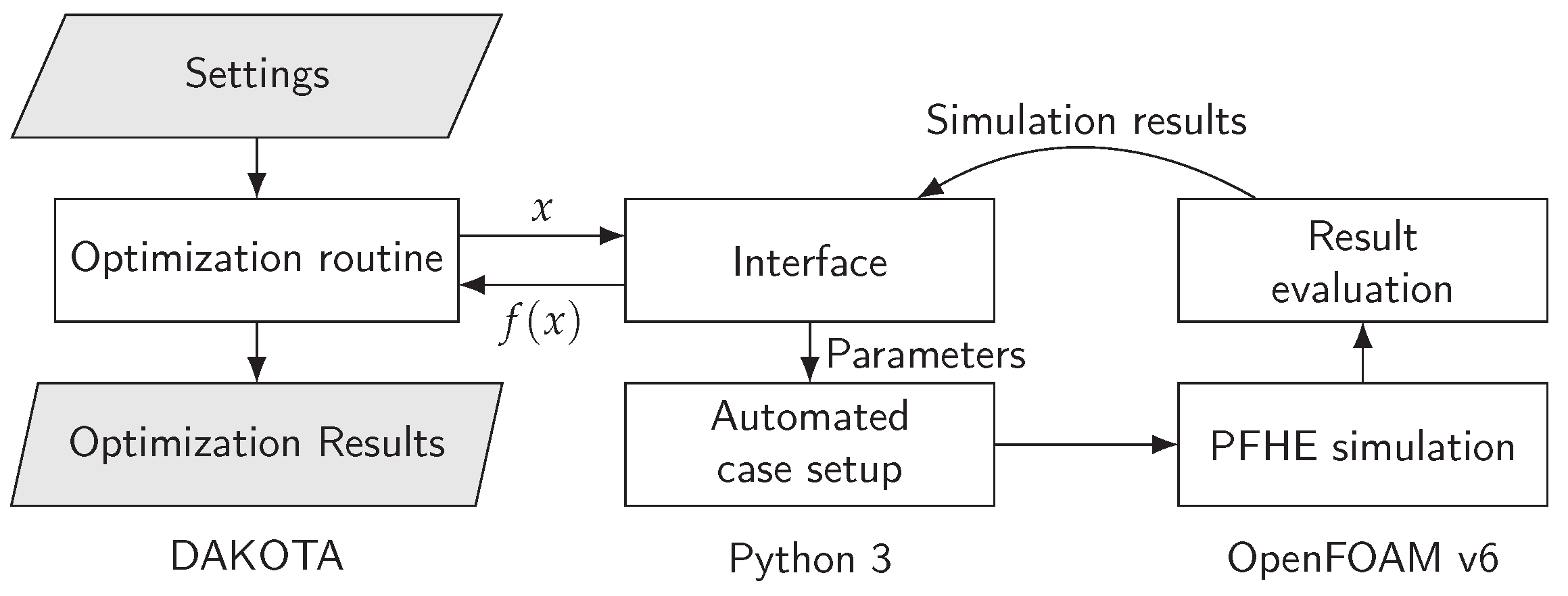
This work presents a general method for the optimization of PFHEs. The basis of the approach is the combination of a detailed and automated simulation model with a flexible optimization routine. The optimization routine is implemented in DAKOTA 6.12 [
37], and each function evaluation results in the setup, execution, and postprocessing of a three-dimensional PFHE simulation. The PFHE model itself is implemented in OpenFOAM v6 [
38] and automated with Python 3 [
39]. To connect the detailed simulation model and the optimization routine, an interface is implemented in Python 3. For each evaluation, the interface passes a set of design variables
x to the automated case setup, controls the execution of a PFHE simulation, and passes the evaluation results
back to the optimization routine. The entire framework is implemented in freely available open source software. A visualization of the framework is shown in
Figure 1.
2.1. Simulation Model
One key element of the modeling framework is the actual simulation model which is used for the evaluation of a PFHE design. In this work, a comprehensive model for both steady-state and transient simulation of PFHE is used. The model itself is described and validated in the earlier work of the authors. Hence, this section gives a brief overview of the most important features. Readers are also encouraged to find more details, an extensive validation, and a detailed PFHE geometry study in the authors’ earlier work on the model [
35,
36].
2.1.1. PFHE Geometry Representation
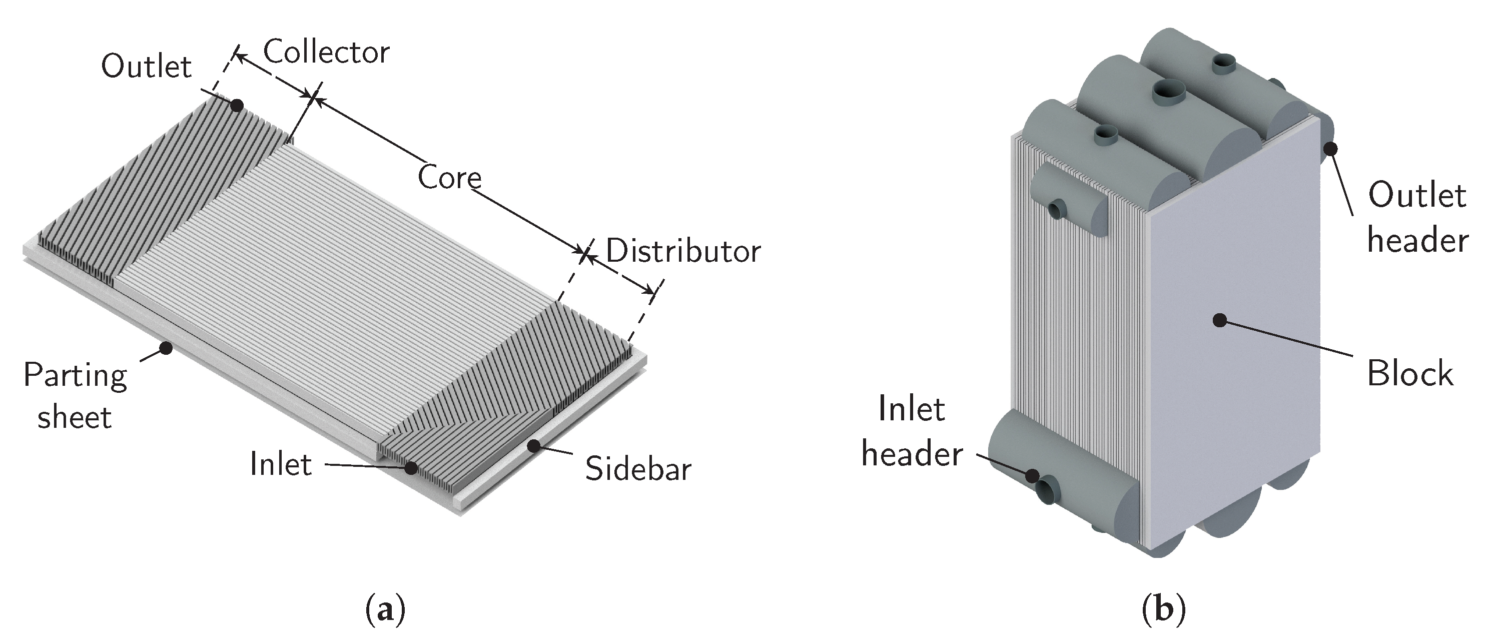
The model in this work uses a very detailed, three-dimensional representation of the brazed block of a PFHE which is represented in
Figure 2. Each layer of the PFHE is captured with its respective collector, distributor, and core fins and the surrounding sidebars and parting sheets. An example of a layer geometry is shown in
Figure 2a. Each process stream flows through multiple equally designed layers, a flow passage, of the PFHE. The layers of different streams are arranged in a specific stacking order. Hence, the design of the block shown in
Figure 2b is a result of the individual layer design and the stacking order.
Headers are used to connect the inlet and outlet of each layer to the surrounding piping of a process stream. However, they do not actively contribute to the desired heat transfer. Hence, their positioning is accurately captured but the headers themselves are omitted in the simulation model.
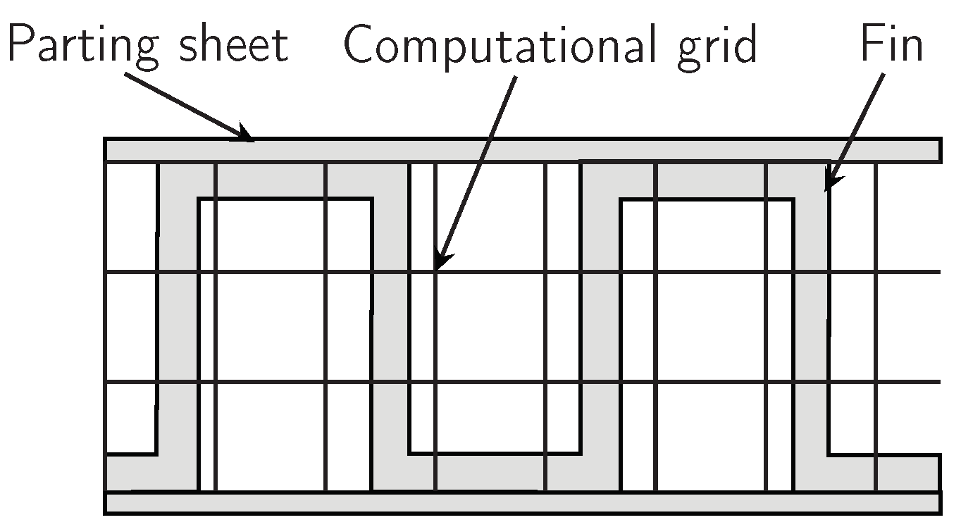
While parting sheets and sidebars are directly resolved by the computational grid, the small-scale geometry of fins, i.e., the individual channels, serrations, and perforations, are not resolved. Instead, a porous modeling approach which allows for the use of a relatively coarse computational grid is employed. The grid is visualized in
Figure 3.
The different orientations of the fin channels in the distributor, core, and collector of a flow passage are accurately captured by the porous medium representing the fin. This approach allows for accurate consideration of the distributors and collectors in the thermo-fluid simulation of the entire PFHE with reasonable computational resources. The porous modeling approach is described in great detail in the original articles on the simulation model [
35,
36].
2.1.2. Mathematical Modeling
The simulation model is based on the solver
chtMultiRegionFoam available in OpenFOAM v6 and uses a finite volume discretization of the governing equations. Sidebars and parting sheets are treated as solids and mathematically described with an energy equation as given in Equation (
1), where
denotes density,
h is enthalpy,
t is time,
is thermal conductivity, and
T denotes temperature [
36]:
Each process stream is treated as a separate compressible fluid with a unique set of thermophysical properties. Each fluid is mathematically described by an energy equation, a momentum equation, and a continuity equation. Since, as seen in
Figure 3, the interface between fluids and fins is not explicitly resolved by the computational grid, respective source terms are added to the momentum and energy equations. These source terms are used to model heat transfer and pressure drop occurring at the non-resolved surfaces between fins and fluids based on established correlations taken from Kays et al. [
4]. A detailed description of how these correlations are implemented in a three-dimensional geometry using the source terms can be found in the authors’ earlier work [
36].
The continuity equation of a process fluid is given in Equation (
2), where
denotes the vector of the velocity field [
36]:
The energy equation of process fluids is given in Equation (
3), where
k denotes kinetic energy,
p is pressure,
is the stress tensor,
is the gravitational acceleration, and
is the respective source term for convective heat transfer between fluid and fin [
36]:
The source term
is used to implement empirical correlations for convective heat transfer based on measurements of the Colburn factor of the fin material [
4].
The momentum equation of process fluids is given in Equation (
4), where
denotes the respective source term for flow resistance caused by interactions on the surface of fins [
36]:
The source term
is used to implement empirical correlations for flow resistance based on the Fanning friction factor of the fin material [
4].
Fins are treated as porous solids because their actual geometry is not resolved by the computational grid as visualized in
Figure 3. Hence, they are described with a modified energy equation containing the source term
for convective heat transfer with process fluids as given in Equation (
5) [
36]:
The cells are considered to be porous, meaning that they are only partially filled with solid material. The porosity is directly linked to the fin geometry and can be calculated directly from its dimensions [
35]. Porosity is reflected in the energy equation via the reduced density and thermal conductivity of the solid material, accounting for the fact that the solid volume is only a fraction of the cell volume. This approach averages small variations on the scale of individual channels of the fin material in order to save computational resources, while it maintains sufficient accuracy for the proper calculation of temperature and flow distribution in the entire heat exchanger [
36].
Details on the calculation of thermophysical properties, the definition of the source terms for heat transfer and pressure drop, and the solution procedure can be found in the original articles describing the simulation model [
35,
36].
2.2. Multi-Objective Optimization
A practical optimization task for a multi-stream PFHE can have any number of objective functions and design variables. Hence, a general optimization framework that is not tailored to a specific task has to rely on algorithms that work with multiple objectives. Because of the generalized approach presented in this work, possible correlations between objectives and design variables are considered to be unknown. They are only accessible through a numerical solution of the PFHE simulation model, which is thus treated as a blackbox [
40]. Derivative-free evolutionary algorithms are suitable for the global optimization of such tasks [
41]. This work uses the multi-objective genetic algorithm (MOGA) available in DAKOTA [
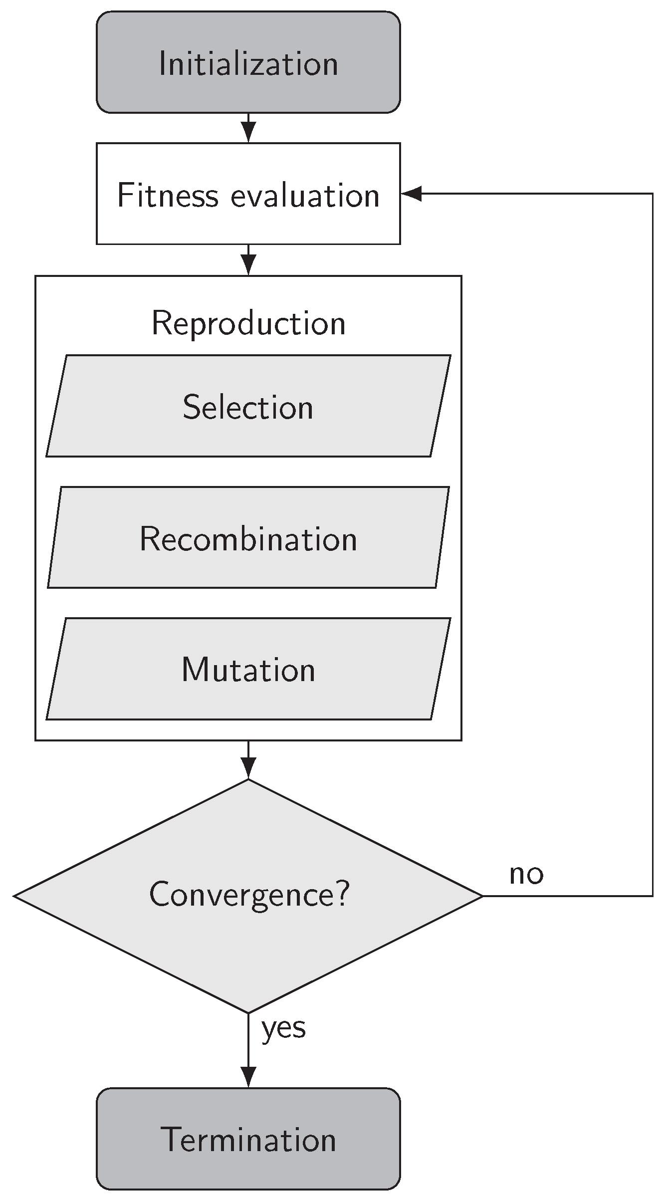
37]. A simplified flowchart of the genetic algorithm is shown in
Figure 4.
In a genetic algorithm, a set of design variables
x is referred to as an individual. Multiple individuals are created in the initialization step and referred to as a population. The fitness
of each individual is evaluated by using the fitness function, i.e., the PFHE simulation model. After evaluation of each individual in the first population, the reproduction process creates a new population to continue the algorithm. The main steps of reproduction are the selection of individuals with desirable fitness, recombination of multiple individuals to form new individuals, and mutation, which randomly changes parts of randomly selected individuals. The algorithm continues until certain criteria for its convergence or termination are reached. The interested reader is encouraged to find a more detailed description of genetic algorithms in the respective literature [
41,
42].
The advantage of using DAKOTA in the presented optimization framework is that the application is not limited to one algorithm. Instead, the MOGA algorithm could be exchanged for other optimization routines available in DAKTOA if required.
2.3. Interfacing
The interface handles all required communications between the simulation model and the optimization routine. After the optimization routine selects a set of variables
x to be evaluated, the interface controls the setup, execution, and evaluation of a corresponding PFHE simulation. Since the simulation model includes an automated setup, the task of the interface is to translate the design variables of the optimization routine to the actual model parameters required by the automation [
35]. After evaluation of the PFHE simulation, the interface returns the processed simulation results
to the optimization routine.
Using an interface instead of directly connecting the optimization routine to the PFHE simulation greatly enhances the flexibility of the modeling framework. In most use cases, not all parameters of a PFHE simulation are considered as independent variables in the optimization routine. The interface is used to handle dependencies between variables that are and those that are not part of the optimization routine. For example, if the fin selection is to be optimized, the interface could adjust the number of layers for each process stream in order to keep a constant overall size of the PFHE despite varying fin dimensions. The interface can further be used to implement arbitrary constraints, which can be useful if the selected routine can only handle linear constraints.
3. Use Case: PFHE Design Optimization
The presented optimization framework uses a comprehensive simulation model which can evaluate the steady-state and transient operation of a PFHE. The optimization routine can be adapted with an arbitrary number of independent design parameters and objective functions. Hence, the framework can be applied to a wide range of use cases in both the design and operation of the apparatus. This work uses a steady-state design optimization as an example study because this task is commonly addressed in the literature.
3.1. Objective Functions
Defining a suitable steady-state design of a PFHE is a typical task in which multiple independent targets have to be achieved: A good design should achieve a high level of performance at a reasonable cost. One possible approach to express these objectives with the results of a thermo-fluid simulation is to use the amount of heat transferred between hot and cold process streams, the pressure drop of each process stream, and the size or weight of the evaluated heat exchanger.
In some applications, it is possible to combine the individual objectives into a single, highly concentrated objective function. In contrast, this case study underlines how the optimization framework can be used with an arbitrary number of independent objectives. Hence, three independent objective functions are treated in this work: thermal efficiency, overall pressure drop, and unit weight.
Thermal efficiency
is a suitable measure of the overall heat transferred from hot to cold process streams. Following the more detailed description given in [
36], it is calculated using Equation (
6):
where
is the total amount of heat transferred, and
is the maximum amount of heat that can be transferred between the process streams. The latter can be calculated from
, the minimum heat capacity flow, and
and
, the averaged inlet temperatures of hot and cold process streams. Hence,
can be calculated from the definitions of the process streams and is independent of the PFHE’s performance. In contrast,
differs for each PFHE design and can be evaluated by volumetric integration of the convective heat transfer source term
in the computational domain
V of all hot or cold process streams as given in Equation (
7):
Because the optimization routine in DAKOTA is set up to minimize objective functions, efficiency is internally transformed to a suitable objective for minimization by using
as the target function.
The overall pressure drop
is calculated by summation of the pressure drops of each individual process stream
i. The pressure drop of each stream is calculated by a comparison of pressure at the inlet and outlet as presented in Equation (
8):
Since the inlet and outlet are two-dimensional surfaces on which the pressure is not necessarily uniform, flow-averaged values are calculated by the simulation model [
36]. As pressure drop should be minimized, the overall pressure drop can be used directly as an objective function.
The unit weight can be calculated by integrating the density of all solid parts of the PFHE, hence parting sheets, sidebars, and fins, in the volume of the computational domain as given in Equation (
9):
The unit weight
M of an optimized design should be minimized; hence, it can directly be used as an objective function.
3.2. Design Variables
In theory, any design variable captured by the simulation model can be used in the optimization routine. In a practical application, each variable vastly increases the number of possible combinations and thus adds to the complexity of the task. In contrast to other optimization studies, the presented framework uses a very comprehensive simulation model that includes many design variables and utilizes a significant amount of computational resources to evaluate each individual design. Hence, it is reasonable to exclude some possible design variables from the optimization routine.
Since numerous previous studies focus on layer arrangement and fin selection, this work excludes these parameters from the optimization and instead focuses on the PFHE sizing, on positioning of stream inlets and outlets, and on the distributor and collector geometries. These geometric details have not been assessed in previous optimization studies because they require a three-dimensional simulation model to be evaluated properly. However, previous work has shown that the configuration of individual stream inlet and outlet positions and geometry type can have a considerable impact on the steady-state performance of a PFHE [
36].
Theoretically, all PFHE dimensions are continuous variables. However, the application of a numerical grid with a certain resolution limits the possibilities to a set of discrete values. The same applies to the manufacturing process, where, typically, only a set of discrete dimensions can be used for any component. To speed up the optimization process, a reasonably large step size can be selected for these variables in combination with a lower and upper bound. The type of distributor and collector for each process stream is treated as a discrete variable. The geometries that are accessible via the simulation model are shown in
Figure 5.
The geometries of type C, D, E, and F are marked with a superscript l or r because they can be mirrored horizontally, resulting in two possibilities for the header position. Hence, 10 different geometry types are available for each distributor and collector, resulting in 100 possible combinations for each process stream.
3.3. Constraints
The presented design optimization is treated without any specific constraints in order to keep it as general as possible. The only constraint considered in this work is that the resulting design has to be feasible for manufacturing. On the one hand, this is achieved by using appropriate lower and upper bounds for the design variables. On the other hand, the geometry types of all process streams have to be compatible with each other. The latter is a rather complicated constraint that is very specific for the task of a PFHE design optimization: The inlet and outlet of each stream have to be positioned so that they do not overlap with those of any other process stream. Otherwise, it is impossible to properly place inlet and outlet headers and facilitate a proper connection of the PFHE to the surrounding piping. The constraint is visualized in
Figure 6.
The MOGA algorithm can only handle linear constraints and thus cannot directly capture the complicated geometric feasibility constraint. However, the interface between the optimization routine and the PFHE simulation is very flexible. Thus, the interface is used to detect designs with an an unfeasible geometry and assigns a very low fitness to them instead of running a real simulation. This behavior saves computational resources and ensures that unfeasible designs are sorted out by the optimization routine.
Studies presented in the literature typically do not require a feasibility constraint because the distributors and collectors are not part of the design variables. However, a similar constraint has been proposed by Reneaume and Nicolut [
5].
5. Results and Discussion
The multi-objective optimization routine does not result in a single design. Instead, it results in a set of Pareto-optimal solutions. A Pareto-optimal design is characterized by the fact that no other design outperforms it in each of the objective functions. In the specific use case of this work, a design can be part of the Pareto-set because it results in the highest efficiency at a certain combination of overall pressure drop and mass.
After the specified optimization run using MOGA with 60 generations and 1000 designs per generation, the Pareto-set contains 1842 designs. The distribution of these designs and the selection of a single optimum are discussed in this section.
5.1. Distribution of the Pareto-Set
In the set of Pareto-optimal solutions, each objective function can be regarded as a separate spatial dimension. A general approach to visualizing the Pareto-set for more than two objectives is to plot multiple two-dimensional projections. The Pareto-set of this optimization with three objective functions can be visualized as shown in
Figure 7 using three two-dimensional projections. Each design in the Pareto-set appears as a data point in each of the three projections.
It can be seen from
Figure 7 that solutions in the Pareto-set spread over a wide range of objective function values. The combined pressure drop
ranges between 110
and 522
, the thermal efficiency
between
and
, and the unit mass
M between 282
and 3190
. For visual reference, the utopia point is also plotted in the diagrams along with its nearest neighbor. The utopia point is a hypothetical point which shows the best value for each of the three objective functions but does not correspond to an actual design. The utopia point and its nearest neighbor are further addressed in
Section 5.2.
The wide range of results in the Pareto-set shows that there are opposing trends between the different objectives: It is not possible for a single design to achieve the best results in all three objectives, and a tradeoff has to be made. The distribution further indicates that there is a correlation between mass and thermal efficiency, with higher weight leading to higher efficiency. This behavior is expected because a larger PFHE can generally facilitate better contact between hot and cold process streams. The correlations between mass and pressure drop are fairly weak because even large units can show a relatively low pressure drop and vice versa. A possible explanation is that the pressure drop is mainly affected by the geometry type and dimensions of the inlet and outlet, while mass is mainly affected by the outer dimensions of the PFHE. Similarly, correlations between pressure drop and thermal efficiency are not strongly pronounced.
Figure 8 shows the relative frequency of each possible value for each design variable among the Pareto-set. The frequencies are normalized so that uniform distribution would result in a relative frequency of one for each possible value.
The distribution of parameters generally shows that nearly all possible values of the design parameters appear in the Pareto-set. This behavior confirms the opposing trends and the necessary tradeoff between the individual objective functions. No variable shows a uniform distribution. This indicates that each variable is relevant for one or more of the objectives.
Most optimal designs range between and in length, which is near the lower boundary. However, designs with the maximum length of are also present in the Pareto-set, indicating that the higher weight caused by longer PFHEs can be balanced by their increased efficiency. Designs with a width above are rare among the Pareto-set, indicating that PFHEs with high width can hardly make up for their increased weight by lowering pressure drop or increasing efficiency. While the inlet width of process stream 1 and 2 is distributed relatively evenly, stream 3 shows a strong tendency, and stream 4 a weak tendency, towards the upper boundary. This can indicate that stream 3 and stream 4 are more sensitive with regard to an increased pressure drop at smaller inlet and outlet dimensions.
Among the different types of geometries, an interesting finding is that geometry type A does not occur in the Pareto-set, and designs with geometry type B are very rare. The absence of designs with type A geometries is caused by the feasibility constraint. Without further adjustments, e.g., by shortening the flow length of one stream, it is impossible to fit the headers of four process streams on a PFHE if one stream uses the type A geometry. The rarity of designs with type B distributor geometries could not be predicted and is an interesting result of the optimization. Using the type B distributor in one process stream drastically limits the remaining space for the other streams at the hot and cold ends of the heat exchanger, which is not beneficial for the overall design according to the results. Another interesting result is that all process streams show high frequencies of geometry type C. This distributor and collector geometry seems to result in the best tradeoff between pressure drop and thermal efficiency for the given process conditions. In contrast, geometry type E appears less frequently among the Pareto-set and is likely not ideal for the specified task.
5.2. Selection of a Design from the Pareto-Set
Without further weighting between the individual objective functions, each design in the Pareto-set can be considered as an optimal solution. However, in an engineering task, one design with a desirable tradeoff between the objectives has to be selected from the Pareto-set.
One way of selecting a design is by using the utopia point as a reference. An optimal design can be selected by picking the nearest neighbor of the utopia point. Since each objective function is represented by a different spatial dimension, each dimension is normalized by the distance between the best and the worst result among the Pareto-set. The nearest neighbor of the utopia point can be selected by searching the smallest distance between any design and the utopia point along these normalized axes. Both the utopia point and its nearest neighbor are shown in
Figure 7.
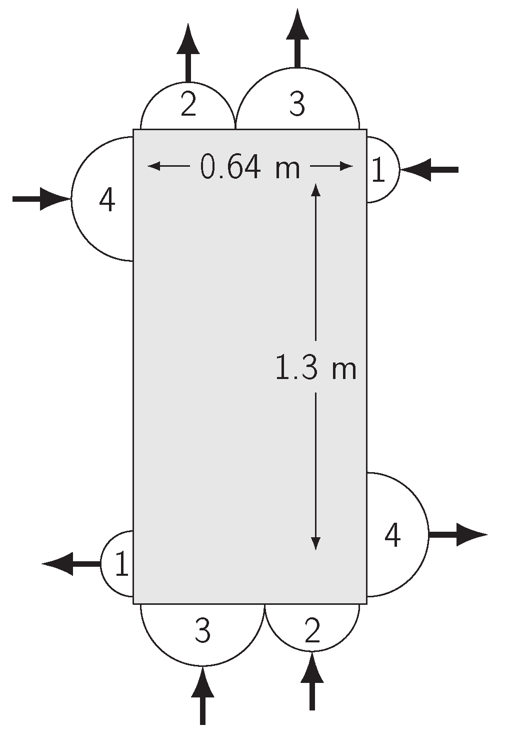
Applying this procedure, the best design for the task is
long and
wide. The outer geometry of the PFHE is visualized in
Figure 9, and the geometry type of each stream is described in
Table 4.
It can be seen that the design does not violate the geometry constraint but fully utilizes the available space at the hot and cold ends of the PFHE with relatively wide inlets and outlets for streams 2 and 3. The optimized design achieves an efficiency of at a combined pressure drop of and a mass of . The design was evaluated in generation 26 of the optimization routine.
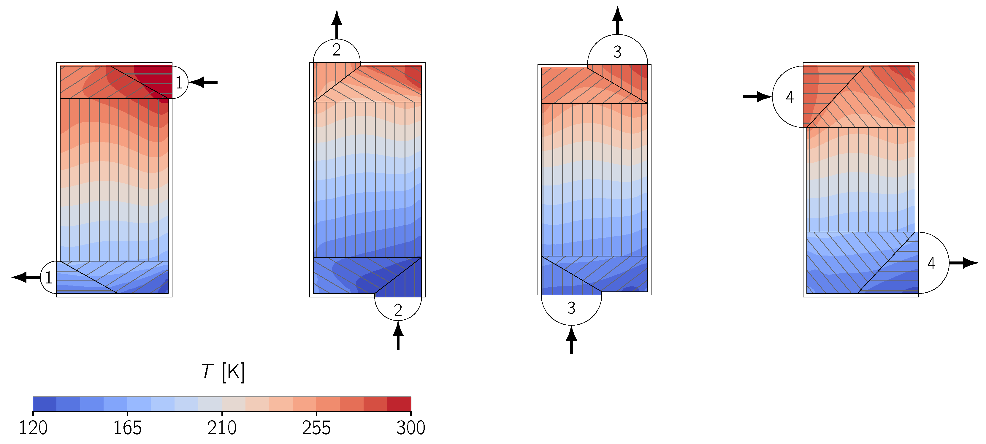
The temperature distribution in the optimized design is shown in
Figure 10 along with a visualization of the detailed stream geometry. It can be seen that the arrangement of the stream inlet positions leads to a relatively even temperature distribution, indicating a balanced thermal design [
11,
36]. The wide inlets of each stream and the selected distributor types favor a low overall pressure drop. The outer dimensions of the PFHE are closer to the lower boundaries specified in
Table 2, leading to a relatively low unit weight. Hence, it is obvious how each of the objective functions influences the PFHE design. Overall, the optimized design can be considered as a well-rounded tradeoff between the desired objectives.
5.3. Relative Weighting the Objective Functions
An advantage of the multi-objective optimization is that the weighting between different objectives occurs only in the last step when a design is selected from the Pareto-set. The weighting does not influence the optimization routine and can easily be altered after the optimization run in order to adjust the tradeoff between the individual objectives.
The weighting can be applied by skewing the normalized axes before picking the nearest neighbor of the utopia point. If the axis of one dimension is shortened, the weighting of the respective objective function increases.
Table 5 shows the performance data of various optimized designs that are selected with different weighting of the objective functions.
It can be seen that by changing the relative weighting between the objectives, designs with different tradeoffs between efficiency, pressure drop, and mass can be achieved. Increasing the weight of one objective always leads to a significant increase in the performance of the respective objective, while the performance of at least one other objective decreases. The weights can be adjusted arbitrarily until a desirable design is found for the engineering task. It is also possible to fully disregard one of the objectives by setting the according weight to zero.
5.4. Computational Effort
In the presented case study, application of the algorithm requires 60,000 evaluations of a three-dimensional CFD model. The numerically efficient porous modeling approach and the periodic boundary conditions facilitate the evaluation of a single simulation within minutes on a single CPU core of a modern workstation. The simulations required for the evaluation of a single generation of the algorithm can be evaluated in parallel, resulting in a nearly linear performance increase with the number of available CPU cores. The results presented in this work are calculated on a 48-core workstation with dual AMD EpycTM 7451 CPUs.
However, the computational effort for each evaluation scales with the size of the PFHE and could drastically increase if the stacking order is not periodic. If a use case requires time-consuming evaluations of large PFHE geometries, it is recommended to split the main optimization task into multiple smaller tasks, each containing a subset of the optimization variables. This approach reduces the overall number of possible variable combinations and thus the number of required function evaluations.
6. Conclusions
This work presents an easily adjustable framework for the multi-objective optimization of plate-fin heat exchangers. A highly detailed simulation model implemented in OpenFOAM is coupled with the external optimization software DAKOTA via an interface programmed in Python. The novelty of this work is that a very comprehensive simulation model is fully automated and employed in combination with a multi-objective genetic algorithm. Hence, the framework can be adjusted to fit the needs of arbitrary practical engineering applications. A task is implemented by the selection of respective objective functions and design variables, while the model and the optimization routine remain unchanged.
One possible use case for the framework is the steady-state design optimization, which is a typical task with multiple opposing objectives and many design variables. The example discussed in this work shows the optimization of a cryogenic PFHE with four process streams and targets high thermal efficiency, low pressure drop, and low unit weight. The design variables are focused on the outer geometry of the apparatus and include the arrangement of inlet and outlet positions and the distributor and collector geometry of the process streams. The task is formulated with three objective functions and a total of ten independent design variables. To ensure that only feasible geometries are evaluated, a tailored geometry constraint for PFHEs is implemented. Since the required computational resources for evaluation of the detailed PFHE simulation are relatively high, some possible design variables are excluded from the study and reasonable upper and lower boundaries are used.
The resulting set of Pareto-optimal solutions gives a good overview of the performance envelope that is achievable under the defined conditions. Both the extension and shape of the Pareto-set and the distribution of design variables among PFHE designs in the set indicate the opposing tendencies of the objective functions, highlighting the necessity of a multi-objective optimization. The best design is selected based on the smallest distance from the utopia point and shows a reasonable geometry with an even tradeoff between the objectives. Relative weighting of the individual objectives can be applied during the selection. Hence, the tradeoff can be steered towards a better fulfillment of a single objective if required.
Application of the optimization framework can yield the fully automated, detailed design of a multi-stream PFHE. The presented workflow is adaptable to any application with multiple objectives and can solve reappearing engineering questions with highly reduced manual labor. This is achieved because a detailed and comprehensive simulation model is used in the optimization framework. Future research could show an application of the framework in a more specialized tasks from the design or operating phase of a PFHE. Another possible topic could be a comparison of the performance of different optimization algorithms in a specific use case.


