Communication

Generation of Photonic Hooks under Point-Source Illumination from Patchy Microcylinders

1
Jiangsu Key Laborotary of Optoelectronics, Nanjing Normal University, Nanjing 210023, China
2
School of Computer and Electronic Information, Nanjing Normal University, Nanjing 210023, China
3
Smart Computational Imaging Laboratory (SCILab), School of Electronic and Optical Engineering, Nanjing University of Science and Technology, Nanjing 210094, China
4
School of Computer Science and Electronic Engineering, Bangor University, Bangor LL57 1UT, UK
*
Author to whom correspondence should be addressed.
Photonics 2022, 9(9), 667; https://doi.org/10.3390/photonics9090667
Submission received: 11 August 2022 / Revised: 15 September 2022 / Accepted: 16 September 2022 / Published: 19 September 2022
(This article belongs to the Special Issue Extreme Photonics)

Abstract

:
Photonic hook (PH) is a new type of non-evanescent light beam with subwavelength curved structures. It has shown promising applications in super-resolution imaging and has the potential to be used in micromachining, optical trapping, etc. PHs are generally produced by illuminating mesoscale asymmetric particles with optical plane waves. In this work, we used the finite-difference time-domain (FDTD) method to investigate the PH phenomenon under point-source illumination. We found that the PHs can be effectively generated from point-source illuminated patchy particles. By changing the background refractive index, particle diameters and the position and coverage ratio of Ag patches, the characteristics of the PHs can be effectively tuned. Moreover, the structure of the intensity distribution of the light field generated from small and large particles can have an opposite bending direction due to the near-field light-matter interaction.

1. Introduction

Photonic nanojets (PNJs) are high-intensity light waves with a subwavelength beam waist generated at the shadow side of illuminated dielectric particles, which have promising applications in various fields such as micromaching, super-resolution imaging, etc. [1,2,3,4]. In 2015, Minin et al. theoretically discovered a new type of PNJ with curved optical fields [5]. They called them photonic hooks (PHs). PHs were later experimentally proved at the terahertz frequency [6], and then at the optical frequency [7]. In 2021, Shang et al. [8] and independently Minin et al. [9] developed a contrast-enhanced microparticle-assisted microscopy, in which the incident light was converted into a PH and induced a near-field asymmetric illumination condition. Asymmetric illumination is a common technique in computational microscopic imaging, which can enhance the contrast of objects [10,11]. Minin’s group also reported a PH-based terahertz microscopy technique [12].
When light waves pass through a dielectric particle whose shape or refractive index distribution is asymmetrical to the propagation direction of light, the difference in phase velocities and the interference of light waves lead to a curved high-intensity focus, i.e., a PH [13,14,15]. Illuminating geometrically asymmetric dielectric particles, such as dielectric trapezoids [5,6,13] and glass cubes [16] embedded dielectric cylinders, with plane waves is a common way to generate PHs. Particles with an anisotropic refractive index distribution, such as Janus particles [14,17], are also suitable for the generation of PHs. In addition, PHs can be generated by partial or nonuniform illumination of symmetric and homogeneous particles [7,18], or by using dielectric particles partially covered with opaque films [19]. For example, Tang et al. used 1–35 μm diameter patchy microcylinders to generate PHs. Half of the cylinder surface is covered with silver films, and PHs with a bending angle of ∼28.4 can be generated under plane wave illumination [19]. In 2021, Liu et al. reported the generation of PHs under point-source illumination [20]. They found that instead of using plane waves, the point-source illumination can also be used to generate PHs from Janus microcylinders, and that the properties of PHs can be effectively tuned by adjusting the parameters of the light source.
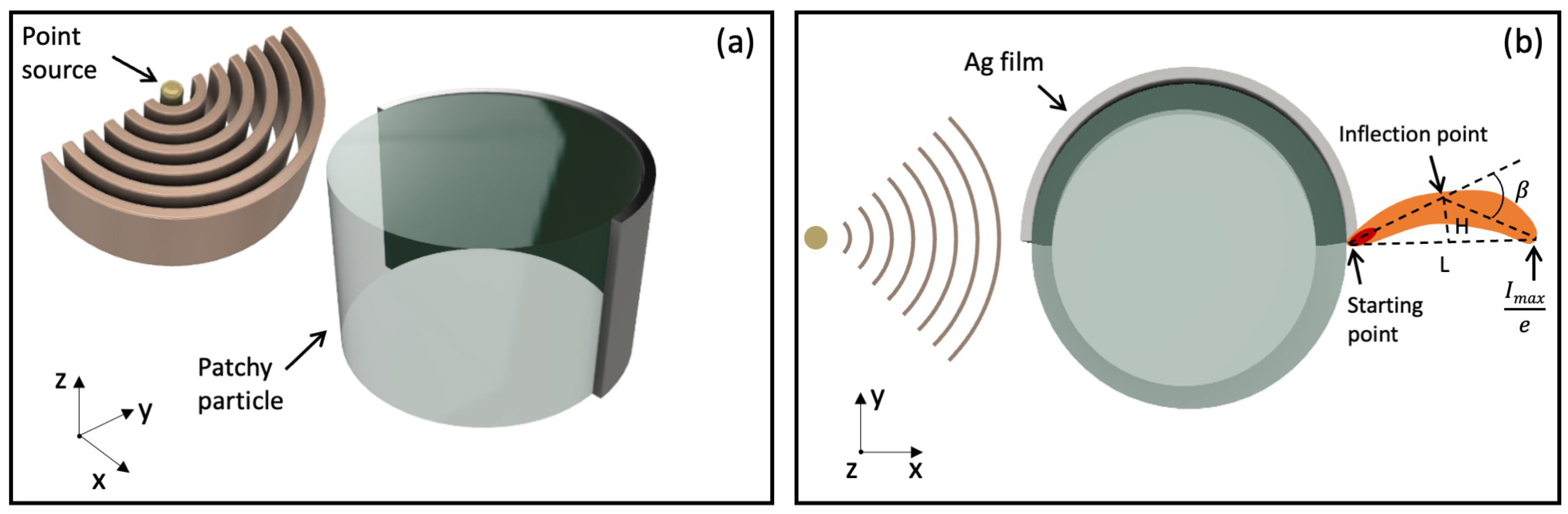
In this work, we show that the generation of PHs can be achieved using patchy particles under point-source illumination. Numerical simulations based on the finite-difference time-domain (FDTD) method were performed to investigate the characteristics of the PHs. By changing the background refractive index (n b g ), particle diameters, the position and coverage ratio of the Ag patches, the characteristics of the PHs, such as the curvature, maximum intensity, length, etc. can be effectively tuned. We also found that the PHs from small and large microcylinders can have opposite bending directions due to the combined effect of the asymmetric energy flow inside the microcylinder and the near-field optical interaction between the light waves and the Ag patches.

2. Simulation Method

Figure 1a,b are the schematic drawings of the 3D stereogram and 2D sectional view of the investigated model. A patchy microcylinder with its surface partially covered with 100 nm-thick Ag films was created for the 2D simulation with the Lumerical FDTD Solutions. As shown in Figure 1b, an intense light field appears on the shadow side of the microcylinder when the cylinder is illuminated by a S-polarized monochromatic point source ( λ = 550 nm). In this study, the microcylinder has a constant refractive index of 1.90, the same as the refractive index of BaTiO3. The diameter of the cylinder varies between 1 and 10 μm and the background refractive index changes between 1.00 and 1.52. The distance between the point source and the microcylinder changes between 0.5 and 5 μm. For the entire computational domain, non-uniform meshes with RI-dependent element size were used, and all of them are smaller than λ /50. The perfectly matched layer was set as the boundary conditions for the simulation region.
As shown in Figure 1b, the curvature of the PH can be defined by the bending angle β , hook height increment H and the length L of PH [21]. We found that in this work, the region of the maximum intensity enhancement is sometimes very close to the edge of the microcylinder. For this reason, the bending angle β was determined by the starting point, deflection point and end point of the PH. The starting point is the point located on the boundary curve between the microcylinder and the background medium, which is defined with the method described in Reference [15]. To determine the starting point, we first analyzed the intensity of the optical fields along the boundary curve, and then the point with the maximum light intensity was selected as the starting point. The end point is the point where the light intensity decays to 1/e of the maximum intensity along the propagation direction of the PH. The deflection point is defined as the point where the perpendicular bisector of the line connecting the starting point and end point intersects the midline of the PH. The bending angle is positive when the deflection point is above the line connecting the starting point and the end point, and negative otherwise. The hook height increment H and the subtense L of the curved photonic flux are also shown in Figure 1b.

3. Results and Discussion

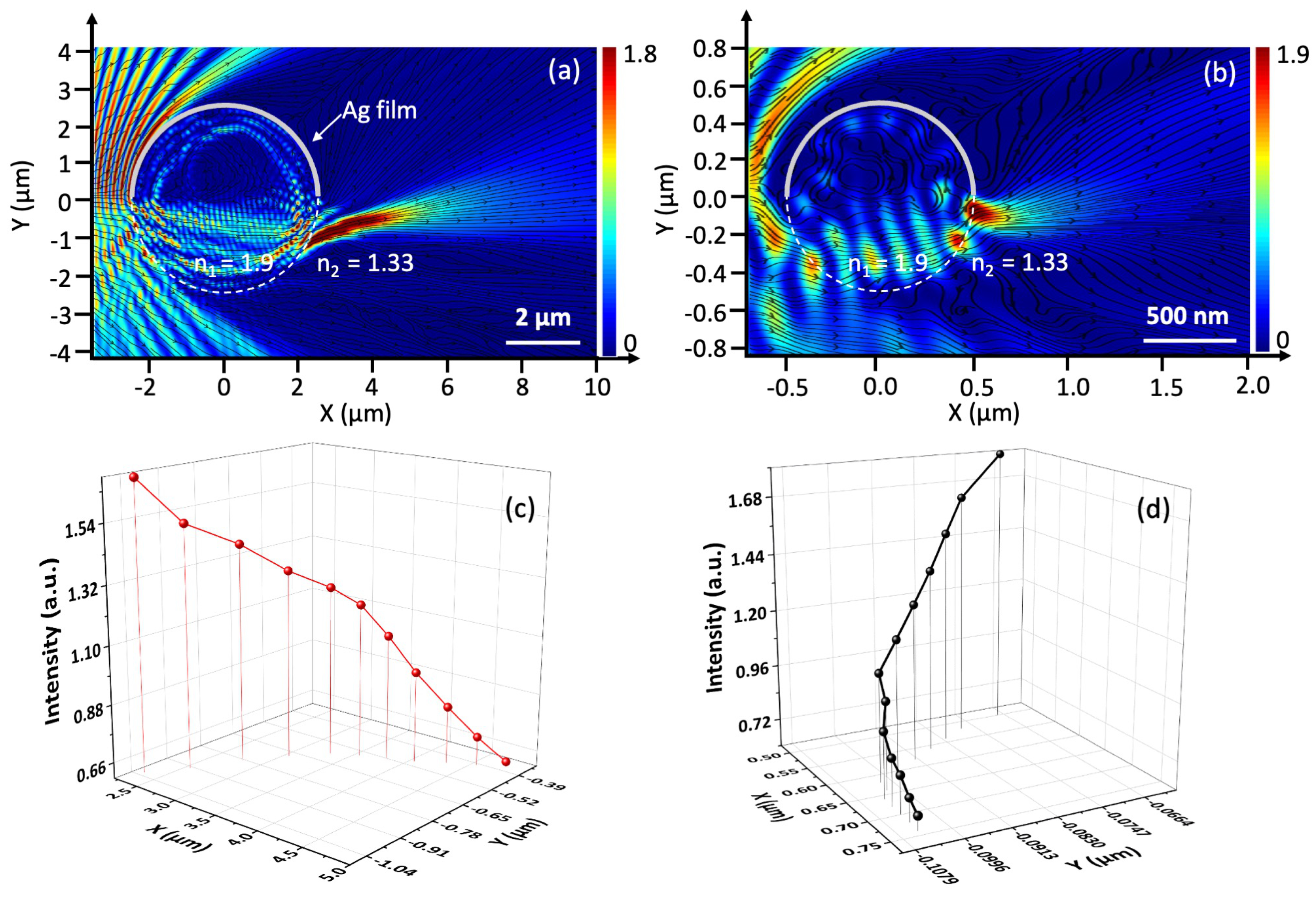
First, we compared the optical fields generated by the 5 μm and 1 μm diameter patchy cylinder. The background refractive index was 1.33. As shown in Figure 2a, a bended optical field can be generated by the 5 μm diameter particle. The obtained PH had a bending angle of β = 13.4 , a hook height increment of H = 0.15 μm and a subtense of L = 2.6 μm. It is interesting to see that the structure of the intensity distribution of the light field bends toward the opposite direction when the particle size decreased to 1 μm. As shown in Figure 2b, the curved optical field had a bending angle of β = −17.1 , a hook height increment of H = 0.02 μm and a subtense of L = 0.24 μm. However, although the spatial intensity distribution generated by the 1 μm diameter patchy microcylinder had a hook-like structure, it was different from the classical PHs described in the previous work [13,15]. The classical PHs have a longer propagation distance of several wavelength [3]. However, the length of the high-intensity energy flux in the 1 μm diameter particle was smaller than the incident wavelength and localized to the near-field region. The 3D trajectory of the I m a x points shown in Figure 2c,d also confirmed the change of the bending directions of PHs. The I m a x points were obtained by slicing the optical fields along the Y-axis and then plotted the coordinates of the maximum intensity point in each slice.
The optical fields generated by patchy microcylinders under Gaussian beam illumination are also simulated in this work (Figure S1, Supplementary Material). As for the 5 μm diameter patchy microcylinder, the Gaussian beam-generated PH has a length of 1.6 μm, which is shorter than the PHs generated under point-source illumination (L = 2.6 μm). A larger bending angle of β = 22.5 and a higher intensity of I m a x = 3.2 were observed in the corresponding optical field. The optical fields of 1 μm diameter patchy microcylinder under Gaussian beam or point-source illumination showed similar characteristics in terms of the bending angle β and subtense L, but the Gaussian beam illumination led to a higher intensity (I m a x = 2.5).
As reported in previous work [13], the formation mechanism of PHs can be analyzed using the time-averaged Poynting vector. In this work, the Poynting vector of the optical fields of the pristine and patchy cylinders under point-source illumination is simulated with the FDTD method, and the corresponding field-lines of the Poynting vector distribution are shown as black lines in Figure 2a,b. As shown in Figure 2a, because of the presence of metal films, part of the incident light is reflected backward to the free space by the Ag films, which breaks the symmetry of illumination and leads to an unbalanced flow of energy inside the microcylinders. This asymmetric flow of energy is then focused into a curved light beam after leaving the patchy cylinder. As shown in Figure 2b, compared with the 5 μm diameter microcylinder, the starting point of the curved light field formed by the 1 μm diameter microcylinder was much closer to the Ag films. To investigate the reason for the change of the bending direction, we recorded the evolution of the E2 field component for the duration of the simulation (Videos S1 and S2). As shown in Videos S1, when light propagates through a 1 μm diameter patchy microcylinder, it is reflected and diffracted by the Ag film at the right edge of the microcylinder [3]. As a result, the direction of its propagation is significantly changed. On the contrary, the starting point of the PH formed by the 5 μm diameter patchy microcylinders was far away from the Ag patch, so the curved shape of the generated light fields was mainly attributed to the phase velocity difference of the light waves (Video S2). We think that the different bending directions between the light fields obtained from the 1 μm and 5 μm diameter patchy microcylinders could be attributed to the near-field optical interaction between the light waves and the Ag patches.
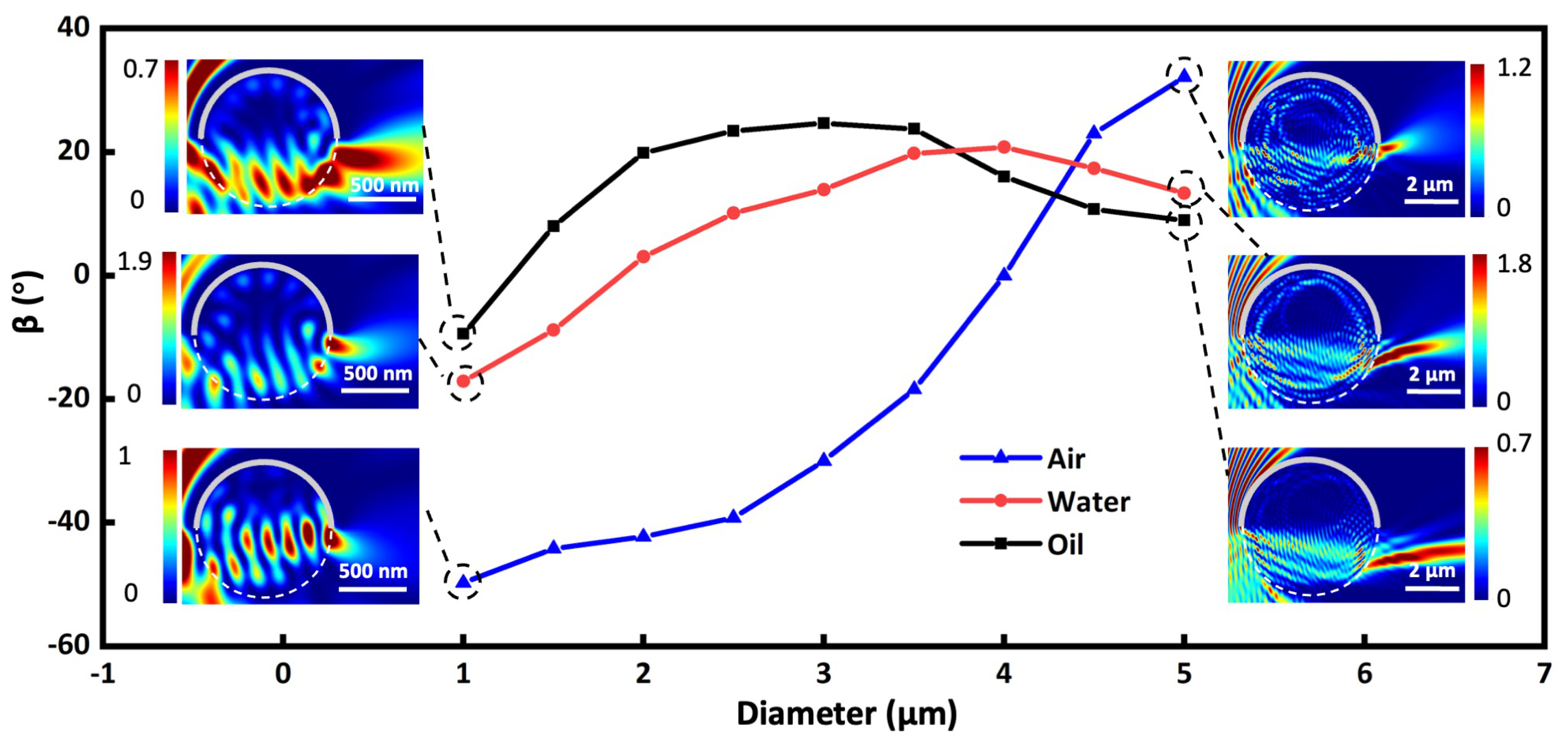
Next, we investigated the influence of the diameter of microcylinders on the bending angle of light fields at three different refractive index contrasts (RIC) between the microcylinder and the background. The diameter of the microcylinder changed between 1 μm and 5 μm, and the refractive index of the microcylinder was 1.90. The background medium was set to air (n = 1.00), water (n = 1.33) and oil (n = 1.52) to obtain a refractive index contrast of 1.90, 1.43 and 1.25, respectively. As shown in the blue line in Figure 3, the optical field generated by the 1 μm diameter patchy microcylinder had an intensity distribution with a bending angle β of around −50 . The bending angle gradually increased to 32 when the particle diameter increased from 1 μm to 5 μm. The curvature of the light fields formed in water (red line) and oil (black line) showed a similar trend; that is, the β increased with the particle diameter and the bending direction turned from downward to upward when the particle diameter became large. We found that the PHs formed in air had the highest curvature compared with its counterparts in water and oil. This could be attributed to the higher refractive index contrast and consequently a larger phase velocity difference between the microcylinder and the background medium. When increasing the particle diameter from 1 μm to 5 μm, the bending angle β of the PHs in water (red line) and oil (black line) increased from −17 to 13 and from −9 to 9 , respectively.
It can be seen from Figure 3 that the bending angles were 0 at some diameters within the range of 1 μm and 5 μm, which means that the optical fields in this case became straight and were similar to a conventional photonic jet. We call this certain particle diameter the critical diameter (CD). In this study, patchy microcylinders with a diameter smaller than the CD generated optical fields with a negative bending angle, and patchy microcylinders with a diameter larger than the CD led to the formation of PHs with a positive bending angle.
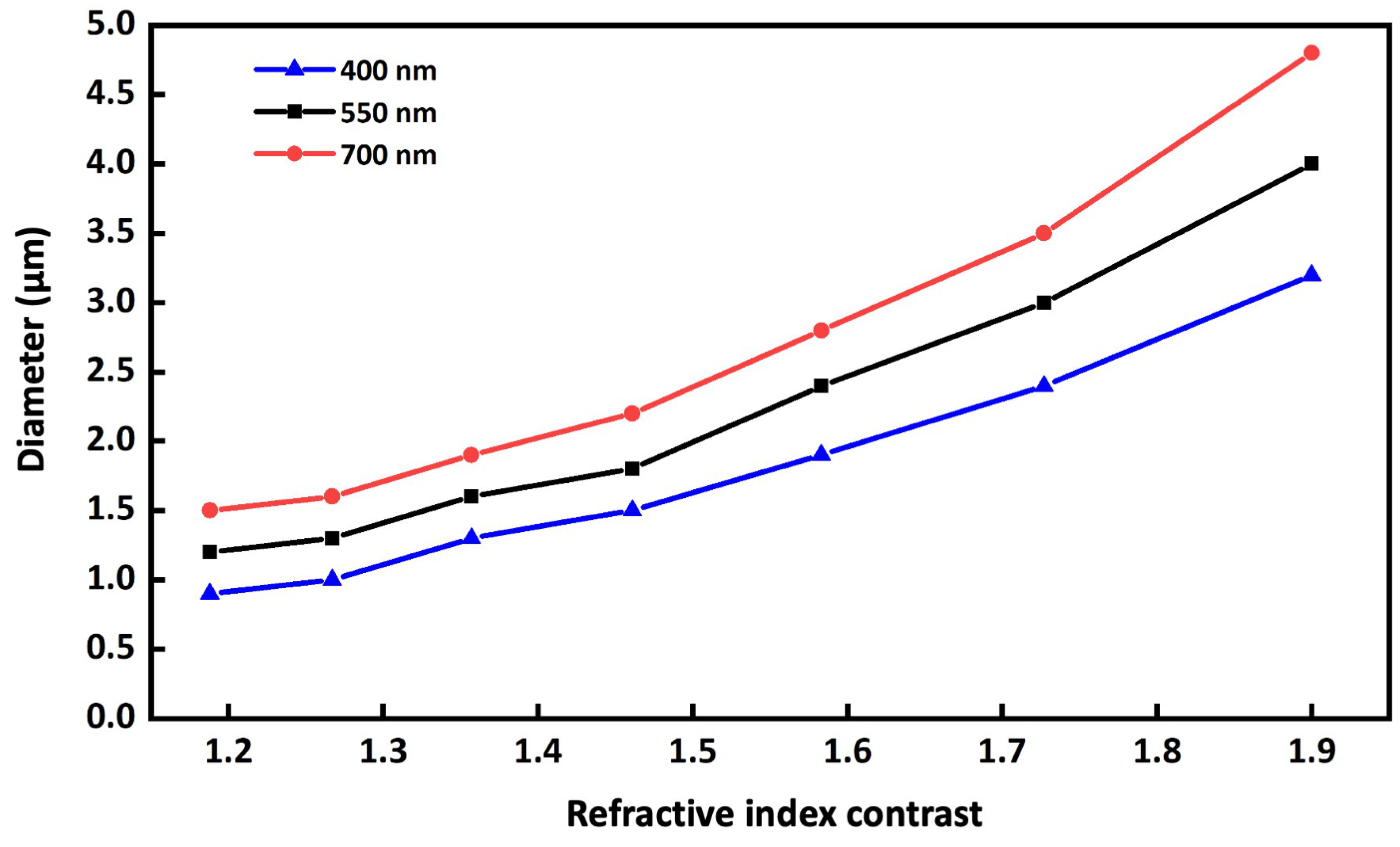
To study the effect of refractive index contrast on the CD of the microcylinder, we increased the refractive index contrast from RIC = 1.19 to RIC = 1.60 and found the CD at each refractive index. Different illumination wavelengths of λ = 400, 550 and 700 nm were used to show the influence of the wavelength on the CD of the particle. The microcylinder here had a constant refractive index of n = 1.9. As can be seen from the red line in Figure 4, when the illumination wavelength was λ = 700 nm, the CD increased from 1.5 μm to 4.8 μm as the refractive index contrast increased from 1.19 to 1.90. We also found that a shorter illumination wavelength led to a smaller CD, as shown in the black and blue lines in Figure 4. The CD increased from 1.2 μm (RIC = 1.19) to 4.0 μm (RIC = 1.90) when the illumination wavelength was λ = 550 nm (red line in Figure 3). For the light fields formed with 400 nm wavelength, the CD increased from 0.9 μm (RIC = 1.19) to 3.2 μm (RIC = 1.90) (blue line in Figure 4).
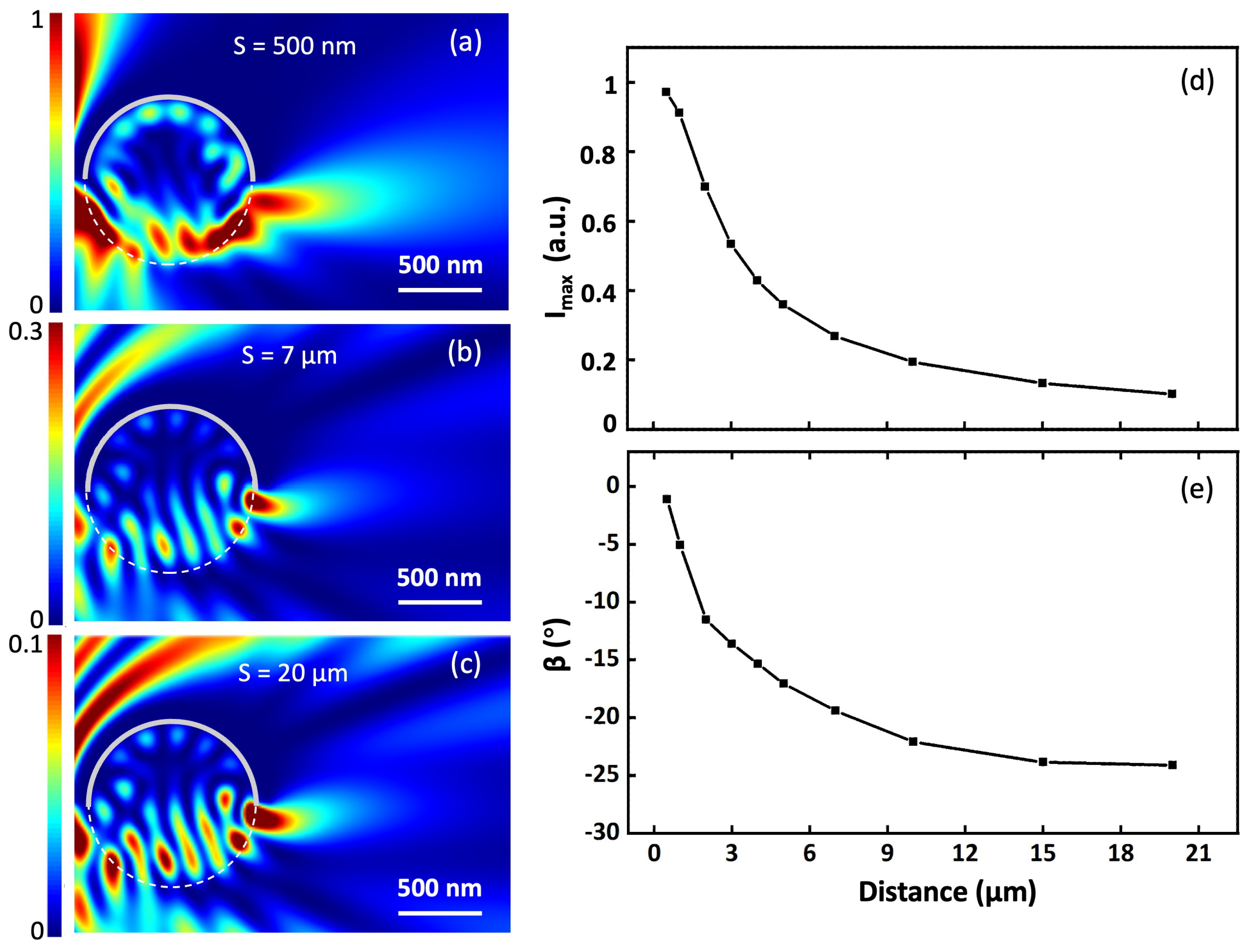
The influence of the distance between point sources and patchy microcylinders on the characteristics of the light fields was also investigated in this work. Microcylinders with a diameter of 1 μm were created for simulation. The upper part of the cylinders was covered with 100 nm thick Ag films. Point sources were positioned at different distances between 0.5 and 20 μm. We defined the distance between the light source and the left edge of the particle as S. As shown in Figure 5a–c, we compared the optical fields formed by the microcylinders when the distance was S = 0.5 μm (Figure 5a), 7 μm (Figure 5b) and 20 μm (Figure 5c). We found that the I m a x position changed with the distance, a closer point-source distance made a further I m a x position. The light fields formed at S = 0.5 μm also had the smallest curvature. As shown in Figure 5d,e, when the distance increased from 0–20 μm, the normalized I m a x decreased from ∼ 0.96 to ∼ 0.1 and the curvature became larger as the bending angle β changed from −2 to −25 . As the distance between the point source and the microcylinder increased, the amount of light waves that can be captured and focused by the microcylinder decreased, resulting in a decrease in the intensity of the light field.
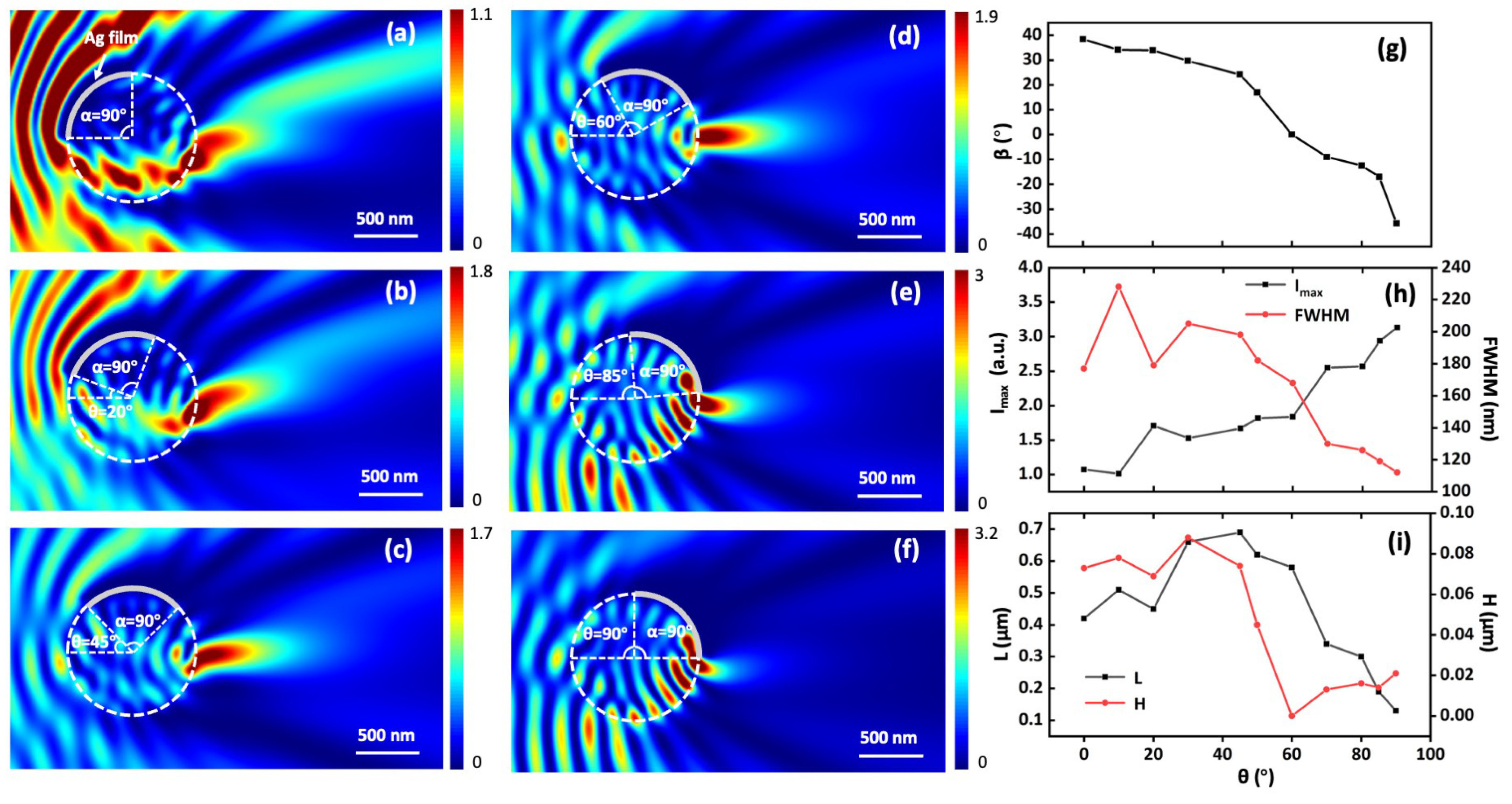
Then, we studied the influence of the position of Ag films on the formation of curved light fields. As shown in Figure 6, a patchy microcylinder with a diameter of 1 μm and a refractive index of 1.9 was used for this study. The cylinder was assumed to be fully immersed in water, so the background refractive index was set to be 1.33. The top surface of the cylinder was partially covered with 100 nm thick Ag films. The opening angle α of the Ag film was constant at 90 . To generate a curved light field at different positions of Ag films, the patchy microcylinder was rotated clockwise around its center, and the corresponding optical field of the patchy microcylinder under point-source illumination was simulated with the FDTD method. The distance between the point source and the left edge of the cylinder was 5 μm. The rotation angle of the microcylinder was defined as the angle θ between the horizontal line and the line connecting the center of the microcylinder to the left edge of the Ag film. As shown in Figure 6a–f, we found that the position of Ag films can significantly affect the properties of the light field. The light field generated at θ = 0 bend upward with a bending angle of β = 38 (Figure 6a). After the microcylinder was rotated 60 clockwise, the spatial distribution of the generated optical field became straight, such as a classical PNJ, and had no curved structure (Figure 6d). When the patchy microcylinder was further rotated clockwise, the generated optical field bends downward toward the opposite direction. As shown in Figure 6f, the bending angle reached β = −35.7 when the Ag films had a rotation angle of θ = 90 .
The main characteristics of the light fields as a function of rotation angle θ are shown in Figure 6g–i. As shown in Figure 6g, the bending angle β of the light fields decreases as the rotation angle increases. Figure 6h shows the I m a x (black line) and the corresponding full width at half maximum (FWHM) (red line) of the light fields obtained at different rotation angles. We found that the focusing ability of the microcylinder became stronger as the rotation angle of the Ag film increased, which could be attributed to the fact that more incident light can be collected by the microcylinder when the Ag film has a larger rotation angle θ . The black line in Figure 6i shows that the subtense L of the light fields increased from 0.42 μm to 0.69 μm when increasing θ from 0 to 45 , then L decreased to 0.13 μm at θ = 90 . The height increment (H) of the light fields generated at different rotation angles θ is shown as a red line in Figure 6i. We found that the maximum height increment was obtained at θ = 30 with a value of H = 0.09 μm. Then, the light beams focused by the patchy cylinder had a structure similar to a PJ when θ was 60 with a value of H = 0 μm. When θ was between 60 and 90 , the height increment increased to 0.02 μm as the rotation angle θ increased to 90 . The data of the corresponding optical fields is shown in the Table S1 (supplementary material).

4. Conclusions

In conclusion, the generation of curved light fields using patchy microcylinders under point-source illumination was investigated in detail in this study. The patchy microcylinders are dielectric cylinders whose surface is partially covered with Ag thin films. Numerical simulations based on the FDTD method were used to investigate the characteristics of the light fields. By changing the diameter of microcylinders between 1 μm and 5 μm, the curvature of the light fields can be changed between −50 and 32 . The light fields generated from small and large microcylinders show opposite bending directions and the critical diameter of the microcylinder is found to be smaller at a larger background refractive index. The simulation results have shown the feasibility of the proposed method as the characteristics of the light fields can be efficiently adjusted by changing the distance between a point source and a patchy microcylinder. The structure of the intensity distribution with a longer length can also be generated if the point source is close to the microcylinder. In this work, we found that the PHs generated by a 5 μm diameter microcylinder have a length of 2.6 μm under point-source illumination and 1.6 μm under Gaussian beam illumination, respectively. We proposed the use of the simulation results for the modeling of photonic hook-assisted microscopic imaging where the light source is close to the target. The maximum intensity and the bending angle of the light fields are smaller at a higher source distance. By rotating a 1 μm diameter patchy cylinder around its center, the bending angle of the curved light field can be changed between −40 and 40 , and the FWHM of the energy flux can be adjusted between ∼0.2 λ and ∼0.3 λ .

Supplementary Materials

The following supporting information can be downloaded at: https://www.mdpi.com/article/10.3390/photonics9090667/s1, Figure S1: The light fields generated by patchy microcylinders under Gaussian beam illumination; Table S1: Characteristics of the light fields generated by 1 µm-diameter patchy microcylinder under point-source illumination; Video S1; Video S2.

Author Contributions

Conceptualization, R.Y.; methodology, F.T., Q.S. and C.X.; software, F.T. and Q.S.; validation, C.X., J.L. and Y.F.; formal analysis, F.T., Q.S., C.X. and R.Y.; writing—original draft preparation, R.Y.; supervision, C.Y., Z.W., C.Z. and R.Y.; funding acquisition, R.Y., J.L. and Z.W. All authors have read and agreed to the published version of the manuscript.

Funding

This research was funded by the National Natural Science Foundation of China (62105156, 62105151), Youth Foundation of Jiangsu Province (BK20210338), European Regional Development Fund (SPARCII-c81133) and Natural Science Foundation of the Higher Education Institutions of Jiangsu Province (20KJB416002).

Institutional Review Board Statement

Not applicable.

Informed Consent Statement

Not applicable.

Data Availability Statement

The data presented in this study are available on reasonable request from the corresponding author.

Conflicts of Interest

The authors declare no conflict of interest.

References

  1. Zhu, J.; Goddard, L.L. All-dielectric concentration of electromagnetic fields at the nanoscale: The role of photonic nanojets. Nanoscale Adv. 2019, 1, 4615–4643. [Google Scholar] [CrossRef]
  2. Chen, L.; Zhou, Y.; Li, Y. Microsphere enhanced optical imaging and patterning: From physics to applications. Appl. Phys. Rev. 2019, 6, 021304. [Google Scholar] [CrossRef]
  3. Minin, I.V.; Liu, C.Y.; Geints, Y.E.; Minin, O.V. Recent advances in integrated photonic jet-based photonics. Photonics 2020, 7, 41. [Google Scholar] [CrossRef]
  4. Darafsheh, A. Photonic nanojets and their applications. J. Phys. Photonics 2021, 3, 022001. [Google Scholar] [CrossRef]
  5. Minin, I.; Minin, O. Diffractive Optics and Nanophotonics: Resolution below the Diffraction Limit; Springer: Berlin/Heidelberg, Germany, 2015; Volume 4, pp. 43–45. [Google Scholar]
  6. Minin, I.V.; Minin, O.V.; Katyba, G.M.; Chernomyrdin, N.V.; Kurlov, V.N.; Zaytsev, K.I.; Yue, L.; Wang, Z.; Christodoulides, D.N. Experimental observation of a photonic hook. Appl. Phys. Lett. 2019, 114, 031105. [Google Scholar] [CrossRef]
  7. Minin, I.V.; Minin, O.V.; Liu, C.Y.; Wei, H.D.; Geints, Y.E.; Karabchevsky, A. Experimental demonstration of a tunable photonic hook by a partially illuminated dielectric microcylinder. Opt. Lett. 2020, 45, 4899–4902. [Google Scholar] [CrossRef] [PubMed]
  8. Shang, Q.; Tang, F.; Yu, L.; Oubaha, H.; Caina, D.; Yang, S.; Zuo, C.; Wang, Z.; Ye, R. Super-resolution imaging with patchy microspheres. Photonics 2021, 8, 513. [Google Scholar] [CrossRef]
  9. Minin, O.V.; Minin, I.V. Optical phenomenan in mesoscale dielectric particles. Photonics 2021, 8, 591. [Google Scholar] [CrossRef]
  10. Fan, Y.; Li, J.; Lu, L.; Sun, J.; Hu, Y.; Zhang, J.; Li, Z.; Shen, Q.; Wang, B.; Zhang, R.; et al. Smart computational light microscopes (SCLMs) of smart computational imaging laboratory (SCILab). PhotoniX 2021, 2, 19. [Google Scholar] [CrossRef]
  11. Li, J.; Zhou, N.; Sun, J.; Zhou, S.; Bai, Z.; Lu, L.; Chen, Q.; Zuo, C. Transport of intensity diffraction tomography with non-interferometric synthetic aperture for three-dimensional label-free microscopy. Light Sci. Appl. 2022, 11, 154. [Google Scholar] [CrossRef]
  12. Minin, O.V.; Minin, I.V. Terahertz microscope with oblique subwavelength illumination: Design principle. Quantum Elec. 2022, 52, 13. [Google Scholar] [CrossRef]
  13. Yue, L.; Minin, O.V.; Wang, Z.; Monks, J.N.; Shalin, A.S.; Minin, I.V. Photonic hook: A new curved light beam. Opt. Lett. 2018, 43, 771–774. [Google Scholar] [CrossRef] [PubMed]
  14. Gu, G.; Shao, L.; Song, J.; Qu, J.; Zheng, K.; Shen, X.; Peng, Z.; Hu, J.; Chen, X.; Chen, M.; et al. Photonic hooks from Janus microcylinders. Opt. Express 2019, 27, 37771–37780. [Google Scholar] [CrossRef] [PubMed]
  15. Gu, G.; Zhang, P.; Chen, S.; Zhang, Y.; Yang, H. Inflection point: A perspective on photonic nanojets. Photonics Res. 2021, 9, 1157–1171. [Google Scholar] [CrossRef]
  16. Yang, J.; Twardowski, P.; Gérard, P.; Duo, Y.; Fontaine, J.; Lecler, S. Ultra-narrow photonic nanojets through a glass cuboid embedded in a dielectric cylinder. Opt. Express 2018, 26, 3723–3731. [Google Scholar] [CrossRef] [PubMed]
  17. Geints, Y.E.; Zemlyanov, A.A.; Minin, I.V.; Minin, O.V. Overcoming refractive index limit of mesoscale light focusing by means of specular-reflection photonic nanojet. Opt. Lett. 2020, 45, 3885–3888. [Google Scholar] [CrossRef] [PubMed]
  18. Liu, C.Y.; Chung, H.J.; Minin, O.V.; Minin, I.V. Shaping photonic hook via well-controlled illumination of finite-size graded-index micro-ellipsoid. J. Opt. 2020, 22, 085002. [Google Scholar] [CrossRef]
  19. Tang, F.; Shang, Q.; Yang, S.; Wang, T.; Melinte, S.; Zuo, C.; Ye, R. Generation of photonic hooks from patchy microcylinders. Photonics 2021, 8, 466. [Google Scholar] [CrossRef]
  20. Liu, C.Y.; Chen, Y.B.; Li, C.; Chen, W.Y.; Chien, S.C. Photonic hook generated by the Janus microcylinder under point-source illumination. J. Opt. Soc. Am. B 2021, 38, 2938–2944. [Google Scholar] [CrossRef]
  21. Geints, Y.E.; Minin, I.V.; Minin, O.V. Tailoring ’photonic hook’ from Janus dielectric microbar. J. Opt. 2020, 22, 065606. [Google Scholar] [CrossRef]
Figure 1. (a) Schematic drawing of a patchy microcylinder under point-source illumination. (b) The points used to define the properties of the generated PHs.
Photonics 09 00667 g001
Figure 2. (a) Light field formed by a 5 μm diameter patchy microcylinder. (b) Light field formed by a 1 μm diameter patchy microcylinder. (c,d) Corresponding 3D trajectories of the midline of the light fields formed by (c) a 5 μm diameter and (b) a 1 μm diameter patchy microcylinder.
Photonics 09 00667 g002
Figure 3. Bending angles ( β ) of the light fields formed in air (blue), water (red) and oil (grey) as a function of particle diameters. The insets are the optical fields of the PHs generated at certain conditions.
Photonics 09 00667 g003
Figure 4. Critical diameters obtained at different illumination wavelengths as a function of the refractive index contrast between the microcylinder and background.
Photonics 09 00667 g004
Figure 5. Optical fields of the patchy microcylinders with a diameter of 1 μm under point-source illumination at different source distances: (a) S = 500 nm, (b) S = 7 μm, (c) S = 20 μm. (d) Maximum intensity enhancement factor I m a x . (e) Bending angle β .
Photonics 09 00667 g005
Figure 6. Optical fields of the patchy microcylinders with a diameter of 1 μm under point-source illumination at the source distance of 5 μm with α = 90 at different rotation angles: (a) θ = 0 , (b) θ = 20 , (c) θ = 45 , (d) θ = 60 , (e) θ = 85 , (f) θ = 90 immersed in water. (gi) Characteristics of the light field as a function of rotation angle θ : (g) bending angle β , (h) maximum intensity enhancement factor I m a x (black line) and the corresponding FWHM (red line), (i) subtense L (black line) and hook height increment H (red line).
Photonics 09 00667 g006
Publisher’s Note: MDPI stays neutral with regard to jurisdictional claims in published maps and institutional affiliations.

