1. Introduction
With the development of instrumentation, radars, wireless and optical communications, and other modern applications, the bandwidth of signals processed in transceivers has been increasing [
1]. However, the signal bandwidth that a transceiver can accommodate is limited by the electronic components employed, for example, analogue-to-digital and digital-to-analogue converters (ADCs and DACs). The progress of ADCs and DACs in recent decades lags largely behind that of digital signal processing [
2]. Despite the ADCs and DACs with extremely high RF bandwidth (tens of GHz, or even greater than 100 GHz) that are currently available, their high cost hinders transceivers from moving toward higher bandwidths in practical applications.
Microwave photonics is an interdisciplinary research field between microwave engineering and photonics, which studies the generation, transmission, receiving, processing, control, measurement, as well as others, of microwave signals based on photonic technologies [
3]. In the past decade, an increasing effort has been devoted to developing microwave photonic techniques for applications in broadband wireless networks, next-generation radars, electronic warfare systems, and sensor networks [
4,
5,
6].
Photonic time stretch (PTS) is a microwave photonic technique used to slow ultrafast signals in the optical domain, which was first proposed by a research group in UCLA [
7]. PTS exploits the group-velocity dispersion of a dispersive element (DE) to stretch an intensity-modulated chirped optical pulse [
8]. In this technique, an ultrafast electrical waveform within a time duration is modulated on a chirped optical pulse, and then the modulated chirped pulse propagating through a DE leads to further broadening of the pulse, which indicates that the modulating ultrafast waveform is optically slowed. If the bandwidth of a signal is reduced to a sufficient ratio, it can be captured using an electronic digitizer. PTS has found applications in areas such as fast ADCs, spectroscopy, and ultrafast imaging [
9,
10,
11]. There have been many reports of PTS studies. Frequency-dependent RF power fading occurs in a PTS system with double-sideband modulation owing to the nonlinear phase shifting between the optical carrier and sidebands induced by chromatic dispersion, which limits the operation bandwidth of the system. An approach based on single-sideband modulation was proposed in [
12] to overcome this problem. It was shown that a method based on a dual-output modulator can compensate for power fading [
13]. The impact of higher-order dispersion and modulation nonlinearity on the performance of PTS was analyzed and characterized in [
14,
15]. In [
16], a method based on the differential operation of a dual-output push-pull Mach-Zehnder modulator (MZM) was proposed to remove dispersion-induced second-order harmonics and intermodulation products. A method using an asymmetric dual-parallel MZM to suppress even -and odd-order distortions was presented in [
17]. To eliminate the impact of the spectral nonuniformity of pulses on stretched signals, an envelope-removing technique was proposed in [
18]. Since the single-channel PTS has a limited time aperture and therefore is not applicable to the processing of continuous-time signals, the PTS for continuous-time operation based on virtual time gating was proposed and demonstrated [
19,
20].
The PTS technique opens a path for receiving high-bandwidth signals that cannot be captured by conventional ADCs. Therefore, a PTS system can be used as an optical front-end for wideband receivers. If we change the dispersion configuration in a PTS system, the function of the system can be switched to speeding up and not slowing down the input signal, which is referred to as photonic time compression (PTC). The concept of PTC was initially introduced in [
21]; however, there are few reports on the theories, experiments, or applications of PTC. Similar to a PTS system that can be used to reduce the bandwidth of received signals, a PTC system can be used to increase the bandwidth of the signals generated from a DAC. Hence, a PTC system can be used as an optical front-end for a DAC-based transmitter to promote the generation of wideband signals. Furthermore, unlike photonic RF mixers based on external optical modulators, which often shift the carrier frequency but do not change the signal bandwidth [
22,
23], the PTC and PTS can improve the bandwidth of the signals to be transmitted and received.
In this paper, we propose an optical front-end for wideband transceivers that integrates a PTC-based transmitter and a PTS-based receiver. The PTC and PTS systems are able to increase the signal bandwidth of transceivers by using inexpensive and relatively low-speed DACs and ADCs. We present theoretical models for phase modulator (PM)-based PTC and PTS and analyze their characteristics. Design of the transceiver front-end, with an emphasis on the bandwidth match between the PTC and PTS, is discussed. Since the PM-based PTC and PTS have a bandpass response with a sub-octave passband, which are naturally immune to the interference of second-order nonlinearities [
24]. Experiments of single-channel PTC and PTS are implemented. Further simulation results on multi-channel PTC and PTS for continuous-time operation are presented. The proposed transceiver front-end creates a new architecture for wideband signal generation/receiving and has prospective applications in future ultra-wideband communications and radars.
2. System and Model
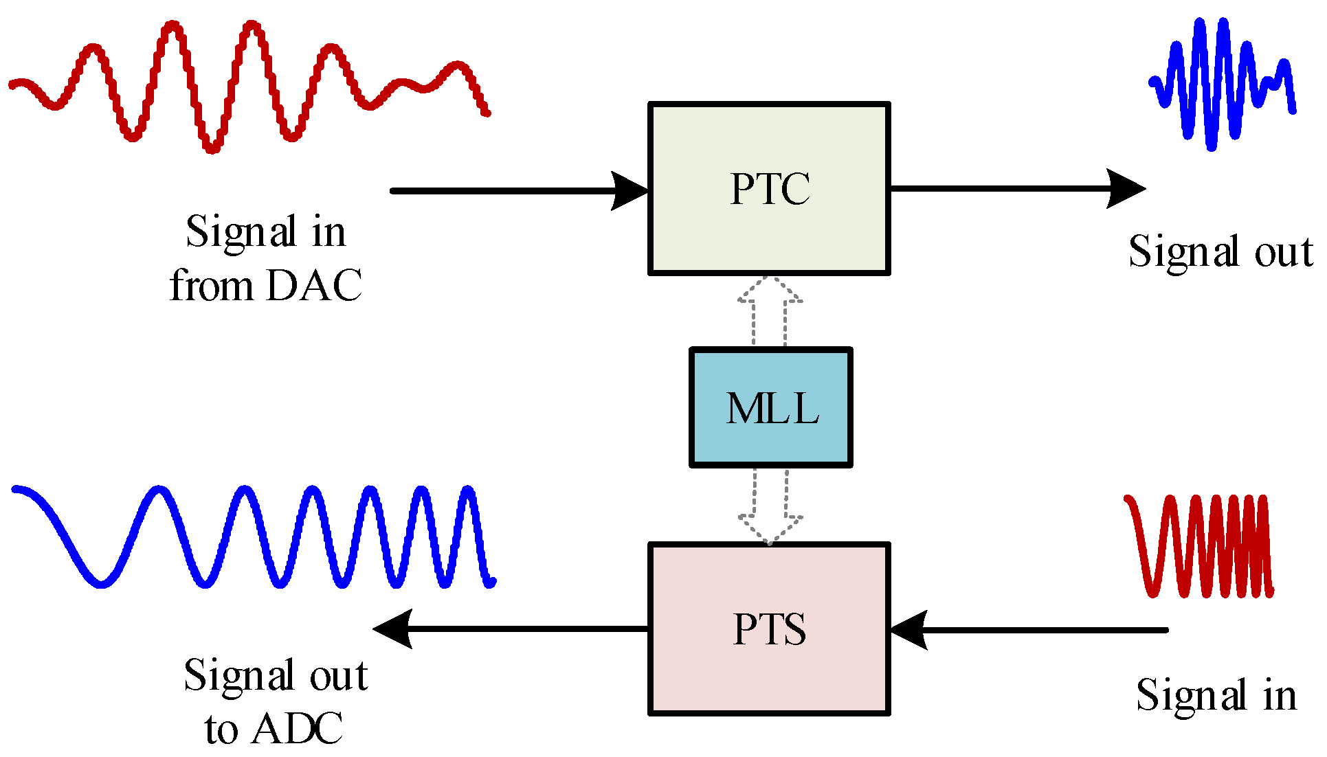
The transceiver front-end is schematically illustrated in
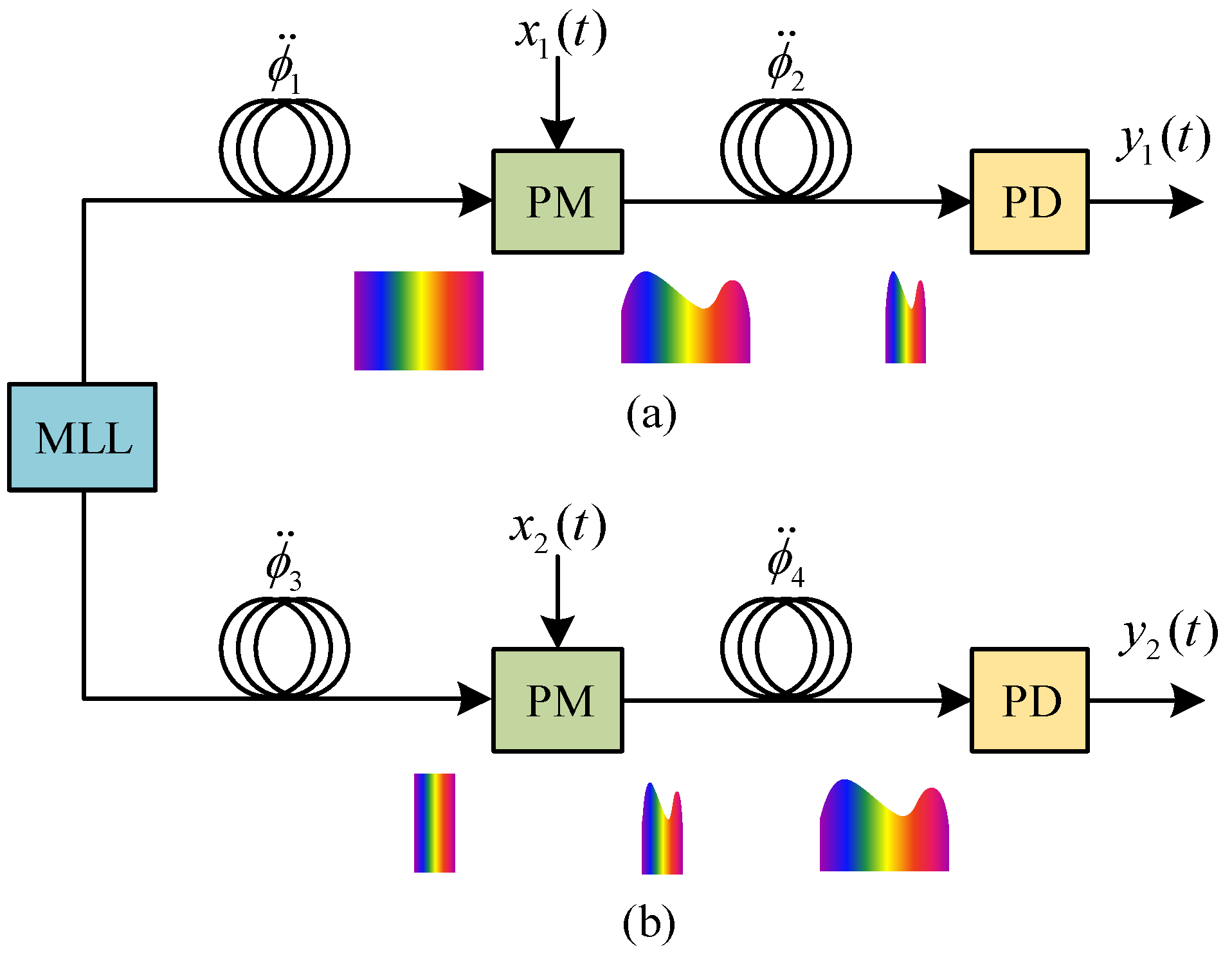
Figure 1, which consists of a PTC system and PTS system. The two systems within the front-end share a common MLL as the pulsed source. PTC generates wideband signals by compressing the input signals from an electronic device (e.g., DAC) in time. The PTS slows down the incoming signals in time or compresses their bandwidths before they can be processed by the following electronic device, for example, ADC. The PTC and PTS within the front-end can be regarded as a postprocessor and preprocessor for transmitting and receiving wideband signals by compressing and stretching the incoming analogue signals, respectively. The diagrams of the PTC and PTS systems are shown in
Figure 2. The PTC and PTS systems have similar architectures but have different dispersion configurations. Both consist of an MLL as the pulsed source, a pair of DEs for pulse compression/stretching, a PM for signal modulation, and a photodetector (PD) for optical-to-electrical conversion. In the PTC system, the DE after the PM has an opposite dispersion sign and is less dispersed compared to the DE prior to the PM, which results in the compression of the modulated pulse in time. However, in the PTS system, the DEs placed prior to and after the PM have the same dispersion sign, which leads to a further broadening of the modulated pulse.
Assume that the output pulse from the MLL is Gaussian-shaped and transform-limited, its time-domain expression in an electrical field can be given by , where is the amplitude of the pulse and is the half width at maximum of the pulse. The RF signals injected into both systems are sinusoidal signals with the frequencies of (PTC) and (PTS), respectively. The dispersion values are and for PTC, and for PTS. It should be noted again that has an opposite sign to (and ), but has the same sign to .
Similar to the theoretical results in PTS [
7,
24], the time-domain expressions of the output signals from the PTC and PTS systems can be written as
and
respectively, where
and
are the modulation indices as
and
; furthermore,
and
are the voltages of the injected RF signals,
is the half-wave voltage of the PMs,
is the compression factor of the PTC,
is the stretch factor of the PTS,
(
) is the half width at
maximum of the pulse after the first DE for both the PTC and PTS.
A proper configuration of the DEs makes
for PTC and
for PTS. It is seen from Equations (1) and (2) that the frequency of the output signal (the cosine term) of PTC is increased to be
and that of PTS is reduced to be
. Both of the output signals are covered by Gaussian envelopes with widths of
and
, respectively. In addition, the sine terms represent a frequency-related power fading introduced by the chromatic dispersion after the PM in both the systems, which is different from the MZM-based PTS systems with a power fading represented by a cosine function [
7]. This property means the PM-based PTC and PTS are bandpass systems. We have verified previously that the 3-dB bandwidth of a PM-based PTS is just slightly less than an octave band, which naturally excludes the impact of second-order intermodulation products [
24].
As a transceiver front-end, it is highly demanded that the transmitter and receiver have the same operation bandwidth. The 3-dB bandwidth, lower-bound and upper-bound of the PTC system can be derived from Equation (1) as , , and , respectively, and those of the PTS system are , , and . It is seen, in order to match the bandwidth between PTC and PTS, the conditions and should be satisfied simultaneously. In addition, it is confirmed that there is for PTC, which indicates that the PTC system also has a sub-octave 3-dB passband, similar to the PTS.
According to the above analysis, for the given compression/stretch factors, the bandpass 3-dB bandwidth of the PTC and PTS systems match with each other if the following conditions are satisfied; that is
where
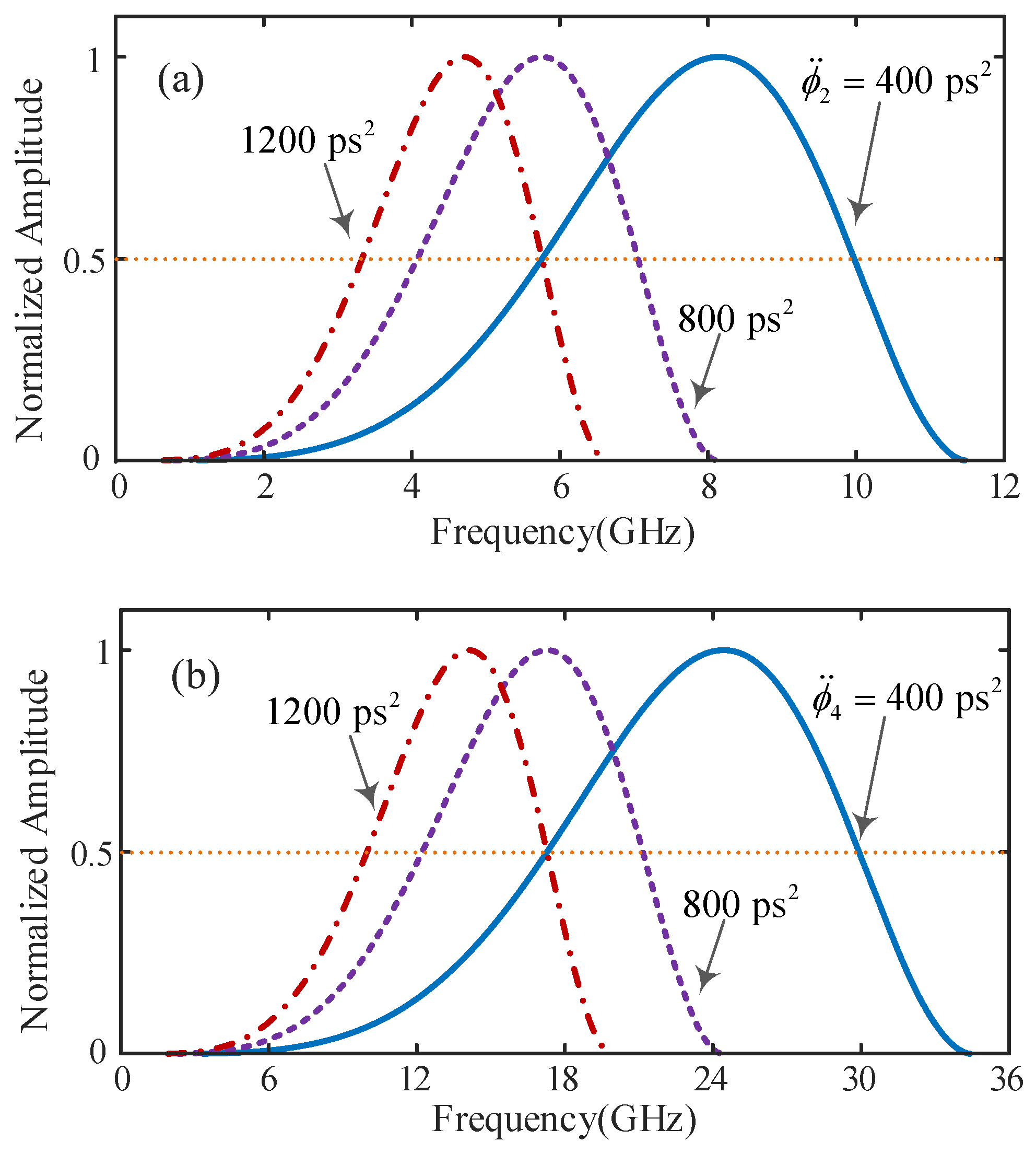
is defined as the companding factor of the transceiver. For example, for a front-end with a given companding factor
, in which the conditions in Equation (3) are satisfied, the frequency responses of the PTC and PTS systems under different dispersion values are given in
Figure 3. It is seen that the passband shifts to a lower frequency and the bandwidth narrows with the increase in dispersion value for both the cases of PTC and PTS. However, the passbands of the two systems always match with each other. It should be noted that the horizontal axes in
Figure 3a,b are the frequency of the incoming signals to be compressed or stretched.
According to the above discussions, in order to obtain greater system bandwidth, smaller dispersion values are demanded. However, larger dispersion values are preferred in order to expand the time aperture within which signals can be processed, which refers to the time duration of a single pulse after passing through the first DE and is given by
and
for PTC and PTS, respectively, where
is the optical bandwidth of the pulse. From Equations (3)–(5), we can get
, which indicates that the PTC and PTS systems within a transceiver also match with each other in the time domain. According to Equations (4) and (5), the time apertures of both systems are proportional to the dispersion value of the first DEs.
Figure 4 shows the time apertures of the PTC and PTS systems under different dispersion values for a given companding factor
, where the conditions in Equation (3) are met. It is seen from
Figure 4 that the time aperture increases with the increase in dispersion value for both PTC and PTS, which is contrary to the above case of the passband.
Now we estimate the time-bandwidth product (TBWP) of the transceiver system [
25]. It is found that the TBWP of the PTC system is equal to that of the PTS system with a matched companding factor and operation bandwidth, which can be written as
Given that , Equation (6) can be simplified as .
There is a time-aperture limitation in either the PTC or PTS with a single channel, as discussed above, which cannot accommodate continuous-time signals. The continuous-time operation of PTS can be achieved based on frequency-domain segmentation and virtual time gating [
25,
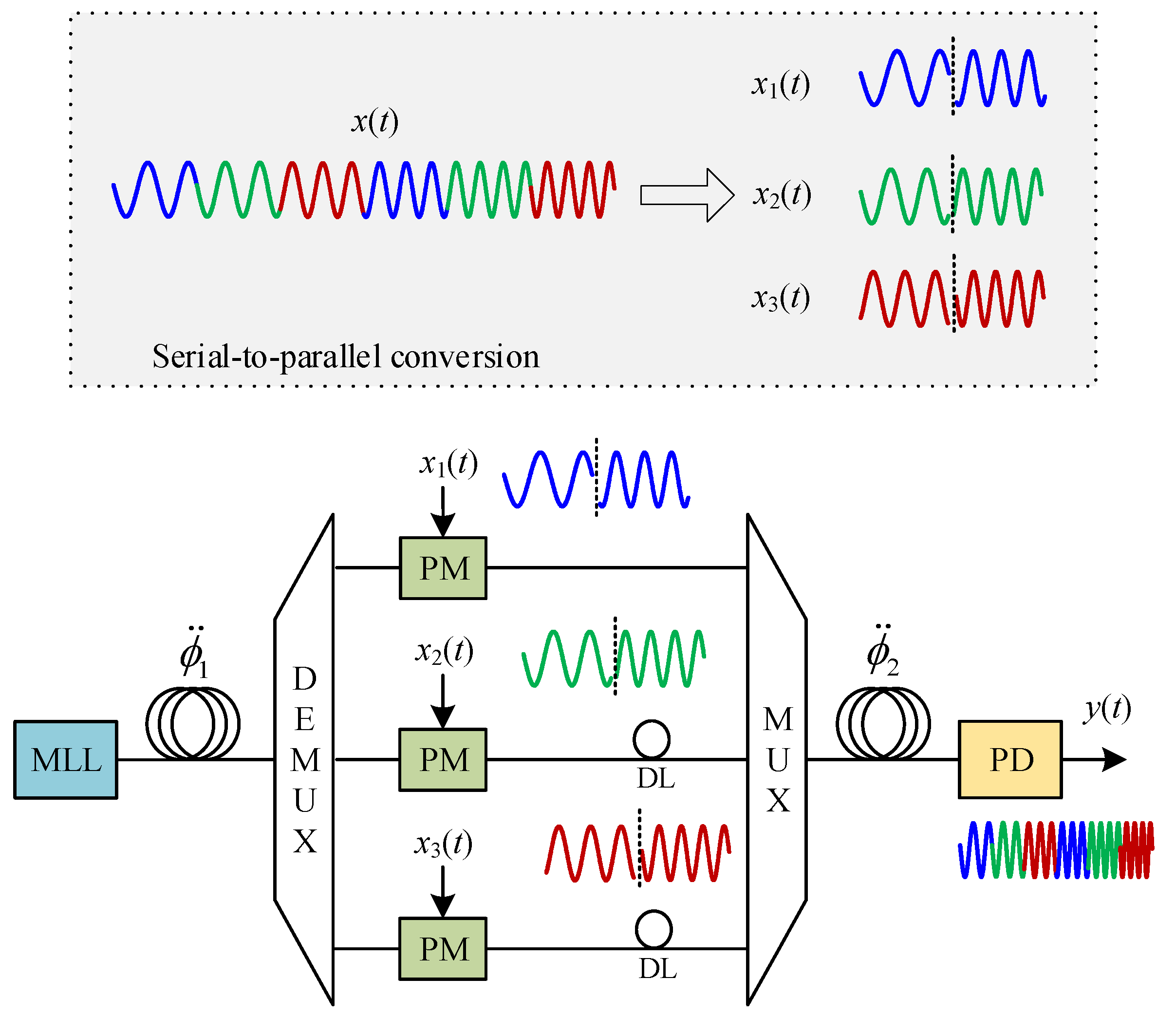
26]. In this work, based on the time-wavelength mapping property of chirped pulses, an improved PTC system for processing continuous-time signals was designed, as shown in
Figure 5. In a digital serial-to-parallel module, the incoming signal that will be compressed in time is first segmented and then interleaved into multiple parallel signals, which will be converted into analogue signals and injected into the parallel optical modulators. Meanwhile, we can see there are some jumps in the input analog signal. In actual situations, the input signal will be distorted slightly due to the limited bandwidth of any electrical system. However, these distortions are located in the edges of each pulse, and their impact is far less than that caused by the spectral edge property. In the continuous-time PTC system, the spectrum of a chirped pulse is divided into multiple channels via a wavelength demultiplexer, which is equivalent to time-domain slicing owing to the time-wavelength mapping property. In each channel, a time-interleaved signal modulated the optical carrier. The modulated optical signals in all channels were combined using a multiplexer. The combined optical signal propagates through the second DE, which leads to a compression in time owing to the opposite dispersion sign of the second DE compared to the first DE. Delay lines can be incorporated into the optical paths between the demultiplexer and multiplexer to adjust the time delay among the different channels. A compressed continuous-time signal is obtained at the output of the second DE. Note that the DEs before and after the modulators can be shared by all channels, which is another major advantage of continuous-time PTC based on spectral segmentation and combination.
Here, we present a simple information capacity analysis on the PTC system shown in
Figure 5 in order to demonstrate there is no loss of information. We assume that the average power and the bandwidth of an incoming signal are
and
, respectively. The information capacity is
, where
is the power spectral density of additive white Gaussian noise. Firstly, the incoming signal is segmented into
parallel channels with powers of
(
,
). After compression by
times in the time domain, the power of the signal in each channel is magnified to be
. In addition, the signal bandwidth is also magnified by
times as
. The information capacity of the compressed signal can be written as
. Since the duration of the incoming signal though the PTC system is reduced by
, the overall amount of information is kept unchanged.
As an extension of single-channel PTS, continuous time stretch and compression have distortion problems similar to those discussed in part 1, including power fading, spectrum unflatness, higher-order dispersion and modulation nonlinearity. Some problems in PTC can be solved by the solutions designed for PTS. However, there is a major difference between PTS and PTC. In PTS, any signal distortions can be compensated or corrected in the digital domain after the PTS module, at least in theory; however, in PTC, digital post-process is not allowed since the output is a high-speed analogue signal.
3. Experiment
An experiment with a setup as shown in
Figure 2 was implemented to demonstrate a transceiver front-end based on PTC and PTS with a matched bandwidth and companding factor. An MLL (Menlo ELMO) with a repetition rate of 100 MHz and a bandwidth over 40 nm in 1550 nm band was employed as the pulsed source. Four coils of standard single-mode fiber and dispersion compensating fiber were used as the DEs, and the dispersion values were
and
for PTC,
and
for PTS, which correspond to a companding factor of
. A programmable optical filter (Finisar WS 4000A) was used to truncate the spectrum to be within 1540–1560 nm and compensate the ripples in the spectral profile. In both PTC and PTS, a polarization controller was placed prior to the PM (Lucent X2622X0001) to minimize polarization dependent loss. RF signals under test were generated by a signal generator (R&S SMB100A). Meanwhile, an erbium-doped fiber amplifier (AESPA-23-B-FA) placed after the PM was used to compensate the link loss in both the systems. A PD (HLT-PD-40) with a bandwidth of 40 GHz was applied for O/E conversion.
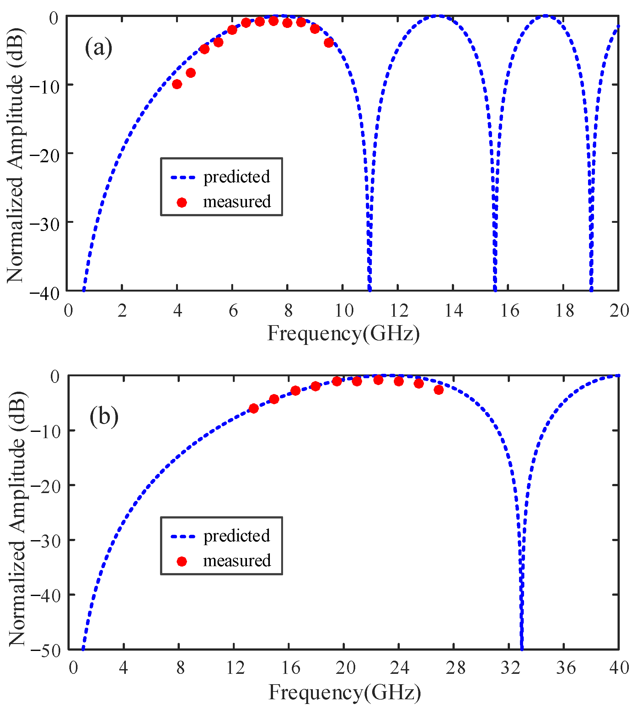
First, we measured the frequency response of the PTC system. The frequency of the RF signal was gradually increased from 4 GHz to 9.5 GHz, while the RF power injected into the PM was fixed at 5 dBm. The RF power of the output signal was measured using a spectrum analyzer (R&S FSV30). The measured power transfer function of the PTC is shown in
Figure 6a, where the horizontal axis represents the frequency of the input signal to be compressed. The measured data are in good agreement with the predicted transfer function. Next, the frequency response of the PTS system was studied. In this case, the frequency of the input RF signal varies from 13.5 GHz to 27 GHz. These results are shown in
Figure 6b. Again, the measured data matched well with the theoretically predicted data. We also observed that the transfer function and operation passband of the two systems matched, as expected, which also verifies the effectiveness of the above design method.
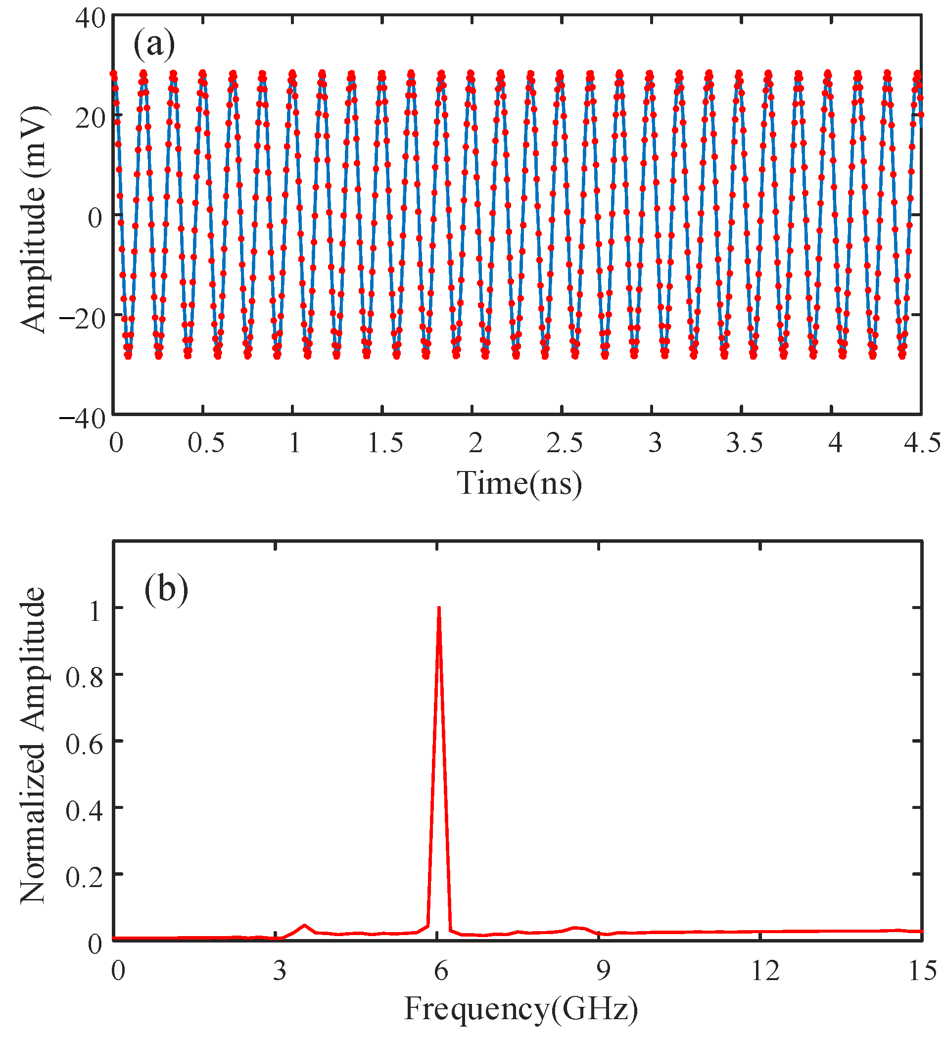
To further study the waveform compression property in the PTC system, we injected an RF signal with a frequency of 6 GHz and power of 5 dBm into the PM, which is within the 3-dB bandwidth of the system. The output signal from the PD was recorded using a sampling oscilloscope (Agilent 86100D), as shown in
Figure 7a. The recorded waveform matches well with the fitted sinusoidal signal at a frequency of 18 GHz. The spectrum obtained by Fourier transform is shown in
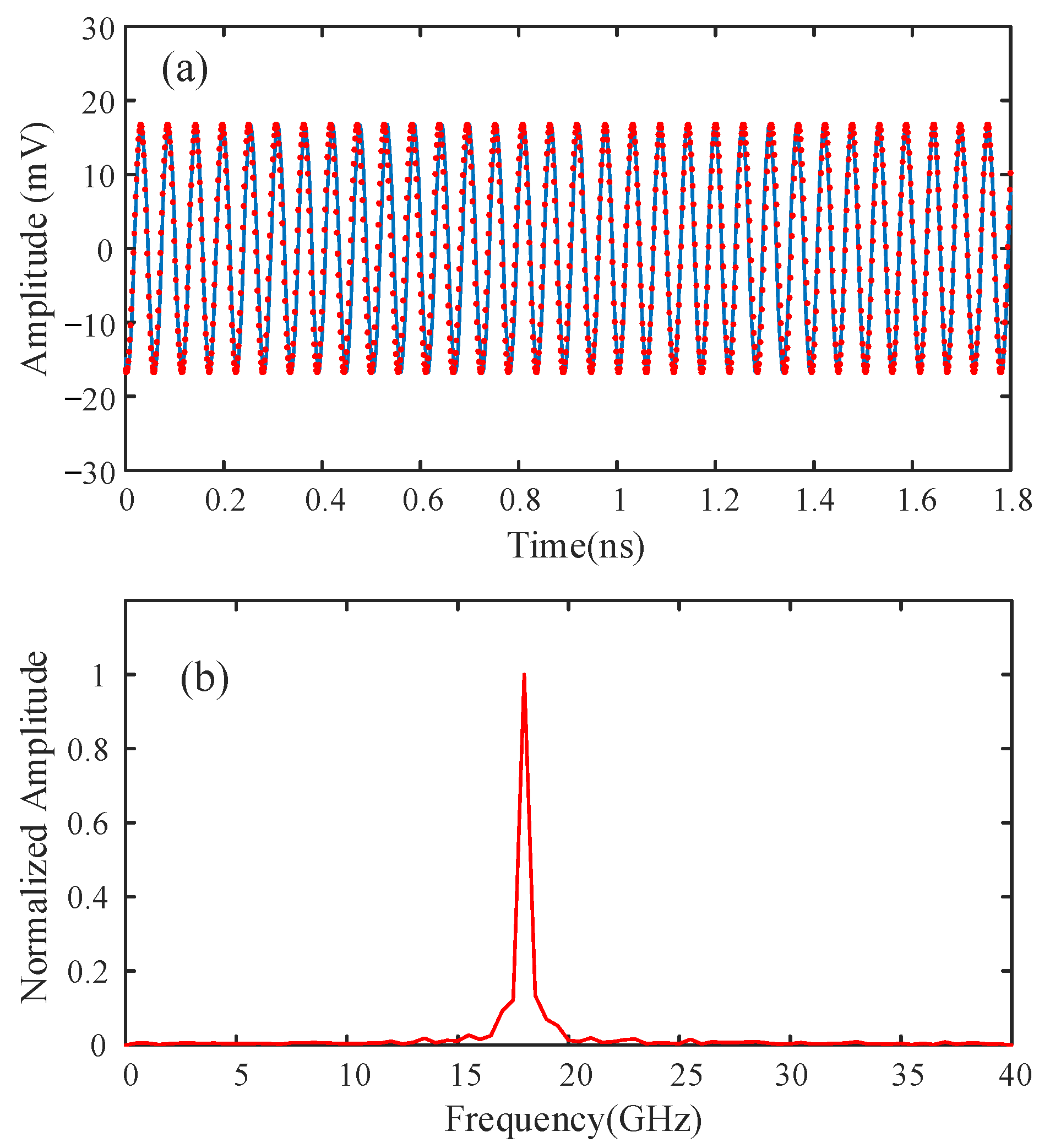
Figure 7b. As expected, the frequency of the compressed signal was 18 GHz, which indicates that the companding factor of the experimental system was 3. Then, the output waveform of the PTS system is recorded when an 18-GHz RF signal is injected into the system. Note that the 18-GHz signal is within the passband of the PTS system.
Figure 8a shows the recorded time-domain waveform captured by the oscilloscope and the fitted sinusoidal signal with a frequency of 6 GHz. The resulting spectrum is shown in
Figure 8b. It clearly shows that the frequency of the stretched signal was 6 GHz, corresponding to a companding factor of 3.
The presented experimental results indicate that in a transceiver based on single-channel PTC and PTS, the operation bandwidth and companding factor of the PTC system are consistent with those of the PTS system within the same transceiver under the appropriate dispersion configuration given in Equation (3).
4. Simulation Results for Continuous-Time Operation
In this section, we study the PTC and PTS systems with multiple channels for continuous-time operation based on computer simulation. It was assumed the spectral range and repetition rate of the applied MLL are 1520–1580 nm and 100 MHz, respectively. The companding factor was three and there were three channels in both the PTC and PTS. The spectrum of the MLL was equally divided into three segments by a demultiplexer. The dispersion values of the four DEs were set to be
,
,
, and
, which were the same as those in the experiment. Therefore, the transfer functions were in agreement with those shown in
Figure 6. In order to better demonstrate the bandpass property of the PM-based PTC and PTS, chirped RF signals were tested as inputs in the simulations.
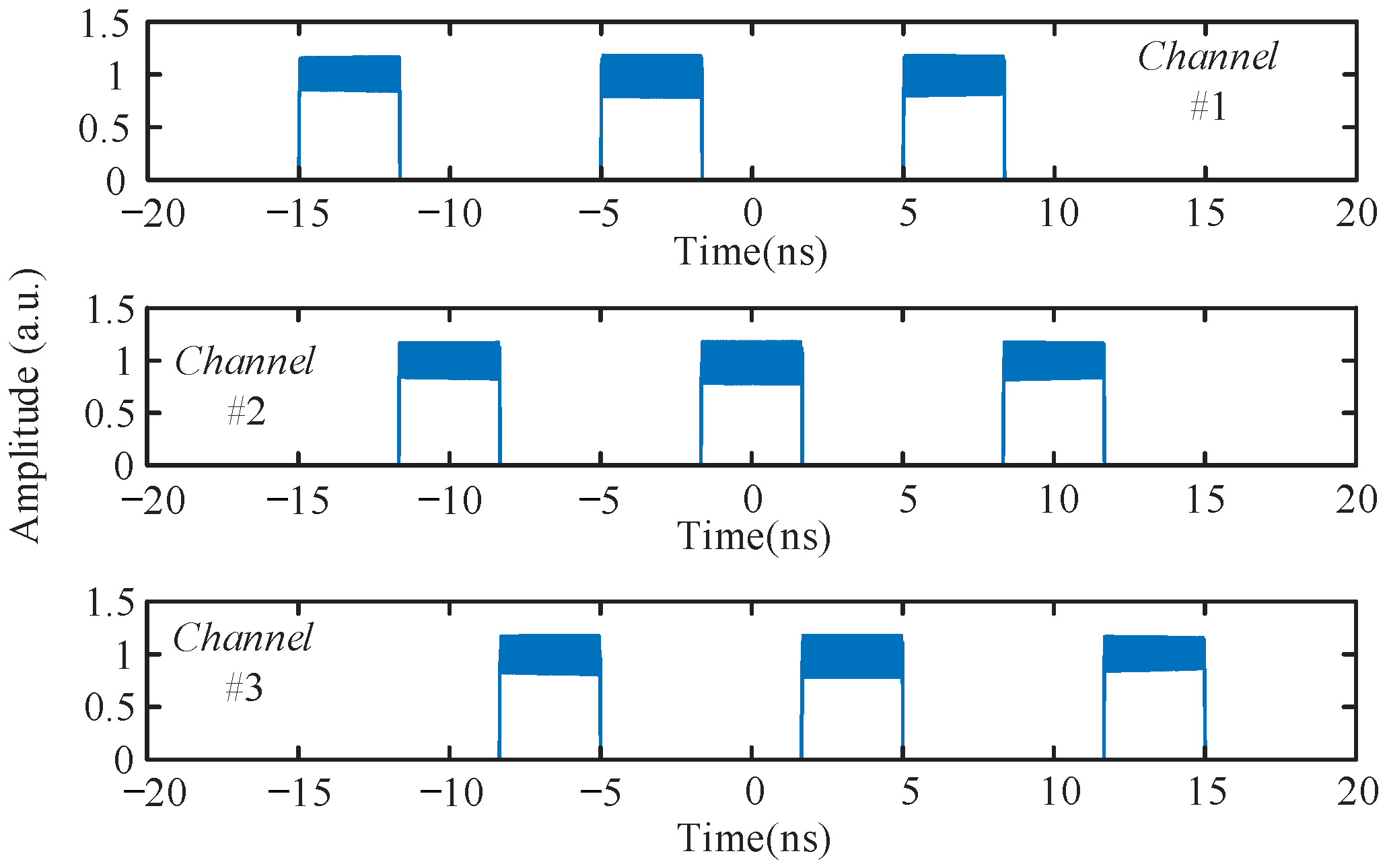
In the simulation of PTC, a chirped RF signal with a frequency range of 5.7 GHz–9.3 GHz and a time duration of 90 ns, which is larger than the time aperture of a single-channel PTC, was first converted into three parallel signals as illustrated in
Figure 5, which are then injected into the three PMs within the PTC. The compressed waveforms of the three channels are shown in
Figure 9. The overall compressed signal after combining in the time domain is shown in
Figure 10a, in which the DC component was removed. An amplitude variation with time was observed, which is due to the time-varying frequency of the chirped RF signal and uneven frequency response within the passband, as shown in
Figure 6. A zoomed-in display on the splicing area of the two-channel signals is shown in
Figure 10b. A slight amplitude ripple is observed in the splicing area. Note that there is no post-processing on the spliced waveforms. We also calculated the spectrogram of the compressed signal based on short-time Fourier transform, as shown in
Figure 10c. The frequency range of the compressed signal is around 17.1 GHz–27.9 GHz, which agrees with the spectral range of the input chirped RF signal for the given companding factor.
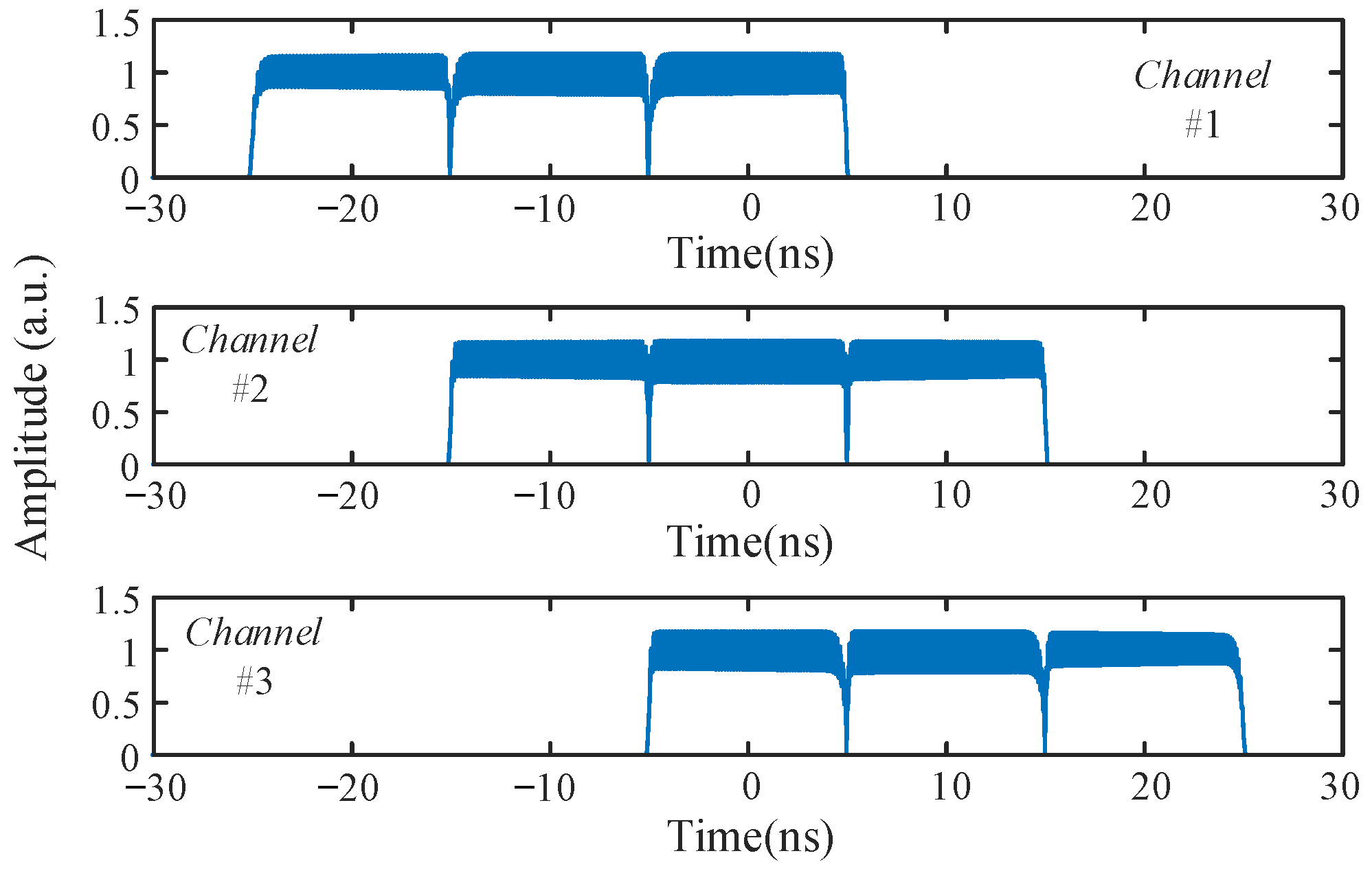
In the simulation of PTS, in order to match the above PTC system, a chirped RF signal with a frequency range of 17.1 GHz–27.9 GHz and a duration of 30 ns was injected into the PM. The stretched signals of the three channels are shown in
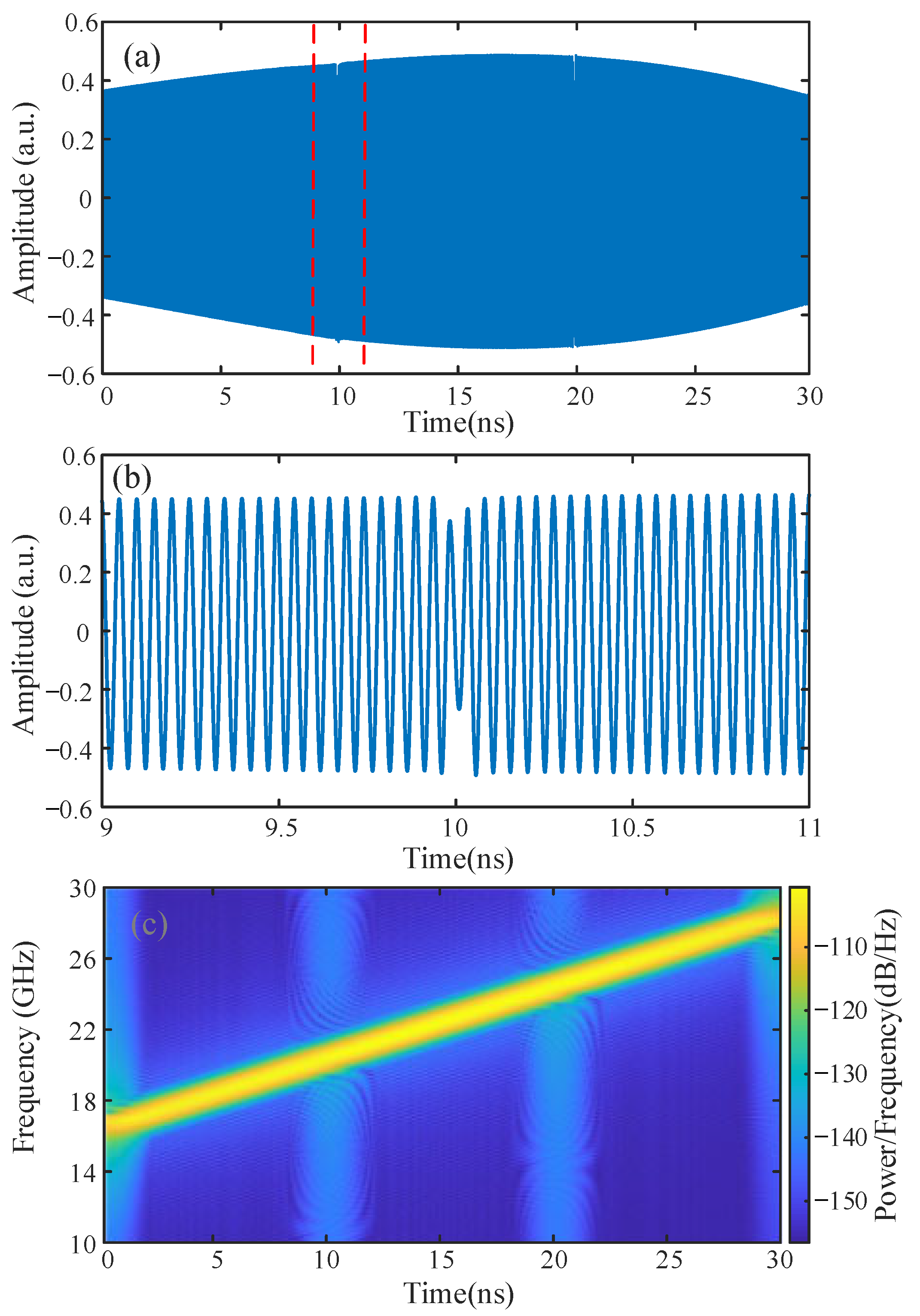
Figure 11. In the PTS, the splicing of the stretched signals can be completed in the digital domain, and a method based on signal processing can be employed to eliminate or reduce the ripples in the splicing area. The overall stretched signal after signal splicing is shown in
Figure 12a, in which the DC component is removed. There is also an amplitude variation with time in the waveform owing to the time-varying frequency of the chirped RF signal and the uneven frequency response within the passband. A zoomed-in display on the splicing area of the two-channel signals is shown in
Figure 12b. Owing to post-processing, the ripple in the splicing area was much smaller. A spectrogram of the stretched signal is shown in
Figure 12c. The spectral range of the stretched signal is around 5.7 GHz–9.3 GHz, which matches well with the spectral range of the input chirped RF signal and companding factor.


