Communication

Designation of Pump-Signal Combiner with Negligible Beam Quality Degradation for a 15 kW Tandem-Pumping Fiber Amplifier

1
College of Advanced Interdisciplinary Studies, National University of Defense Technology, Changsha 410073, China
2
Hunan Provincial Collaborative Innovation Center of High Power Fiber Laser, Changsha 410073, China
3
Hunan Provincial Key Laboratory of High Energy Laser Technology, Changsha 410073, China
*
Author to whom correspondence should be addressed.
Photonics 2022, 9(9), 644; https://doi.org/10.3390/photonics9090644
Submission received: 22 August 2022 / Revised: 4 September 2022 / Accepted: 6 September 2022 / Published: 8 September 2022
(This article belongs to the Section Lasers, Light Sources and Sensors)

Abstract

:
In this paper, the fabrication method of a pump/signal (6 + 1) × 1 combiner based on a large-core (48 μm) multimode signal fiber is introduced. Since the signal fiber is not tapered in the production, and an effective feedback alignment method is adopted during the splice process, the degradation ratio of the M2 value of the signal light is only about 5% after passing through the beam combiner. In addition, with the help of a home-made beam combiner, a counter-directional tandem-pumping amplifier is built. The maximum output power of the amplifier is 15.31 kW with the slope efficiency of 83.2%. The temperature rise coefficient of the home-made combiner is 3.2 °C/kW and the backward isolation degree is more than 36 dB from each pump pigtail. Both test results prove the outstanding potential of the pump-signal combiner in high-power laser applications.

1. Introduction

Fiber lasers have been widely used in various fields such as medical, industrial processing and national defense due to their unique advantages [1,2,3]. With the optimization of the optical fibers and passive fiber devices, fiber lasers have already been able to output powers greater than 10,000 watts [4,5]. Due to the limitation of pump source brightness and nonlinear effects, it is difficult to further increase the output power of fiber lasers [6,7]. Tandem-pumping has been proved to be an effective method to increase the output power of the laser [8,9]. However, because of the low absorption coefficient of the Yb ions for the 1018 nm pump light, the absorption of the pump light is usually increased by increasing the core size and the length of the gain fiber. Except for the tandem-pumping structure, counter-directional pumping scheme is also helpful to suppress the nonlinear effects and transverse mode instability (TMI), which is beneficial to the power improvement for the fiber laser. In this case, a counter directional pump/signal combiner, based on a large mode area signal fiber capable of effectively maintaining beam quality of the system, is crucial.
At present, the pump/signal combiner can be divided into side-pumping combiner and end-pumping combiner. Generally speaking, the signal beam quality of the side-pumping combiner is well maintained as there is no interference on the signal fiber during the whole fabrication process. However, the disadvantage of the side-pumping combiner is that the capable power is limited by the number of pump ports [10,11]. While for the end-pumping combiner, the capable pump power can be extended with the increase of the number of pump ports. However, the signal transmission quality is a serious problem for the end-pumping combiner as the signal fiber must undergo complex operations such as corrosion, cleaving, and splicing.
Various methods have been tried to improve the transmission quality of the signal light in the end-pumping combiner [12,13]. In 2017, Zou et al. came up with a new method to fabricate the (6 + 1) × 1 TFB (tapered fused bundle), in which the taper process of the signal fiber was avoided [14]. In their combiner, the reported signal transmission rate was more than 97% at 150 W injected power with no information about the M2 value. In 2019, Yanran Gu et al. reported a co-directional (6 + 1) × 1 signal/pump combiner which is based on a large core size (50 μm) signal fiber for the first time. Through two built-in mode matching adaptors, the transmitting efficiency of signal light in their combiner was more than 98%. With the help of home-made combiner, Gu et al. built a co-directional tandem-pumping amplifier with the maximum output power of 3068 W and the M2 value of 2.83 [15]. In 2021, Yili Liu et al. reported a (6 + 1) × 1 signal-pump combiner in which the beam quality degradation of the signal light was more than 30% [16]. Yu Liu et al. reported a (6 + 1) × 1 counter-directional pump/signal combiner in 2022 whose signal fiber is a few-mode fiber (25/400 μm, NA = 0.06/0.46). Through active alignment splicing process, the deterioration of M2 value for signal light was about 10% with 1 kW signal power injected [17]. However, the beam combiner is not used in high-power laser systems, so there is a lack of testing for the performance parameters of the beam combiner when high-power pump light and signal light are injected at the same time.
The pump-signal combiner with multimode signal fiber is rarely reported previously. Hence, in this paper, we propose a fabrication method of a pump-signal combiner based on a multimode signal fiber (48/400 μm, NA = 0.08) for the first time, in which the signal fiber is not tapered in the production and the signal transmission quality is well maintained. With the help of a M2 analyzer for in-line alignment and splicing, the signal transmission rate of the fabricated combiner is more than 98%, and the degradation ratio of the M2 value of signal light is only about 5% even with such a large core size. In addition, the home-made pump-signal combiner is applied in a counter-directional tandem-pumped fiber amplifier with a record power of about 15.31 kW. The M2 value of the system gradually rises from 2.86 at 1 kW to 3.03 at 15.31 kW with no apparent TMI occurs. The temperature rise coefficient of the home-made combiner is 3.2 °C/kW and the backward isolation degree (BID) is more than 36 dB from each pump pigtail, indicating the outstanding potential of this pump-signal combiner in high-power laser applications.

2. Theoretical Analysis

Firstly, a simulation software (Rsoft) is used to simulate the transmission of signal light in the combiner. The diagram of the simulation structure is shown in Figure 1: a signal fiber is in the center of the TFB, which is surrounded by six pump fibers and a glass tube. The TFB is tapered down to the diameter of the cladding of output fiber to improve the pump transmitting efficiency. In the proposed scheme, the core parameters of the input and output signal fiber are both 48 μm, NA = 0.08. Theoretically, there is a number of guided modes supported in the signal fiber with such large a core diameter and a slight axial offset during fusion can excite higher-order modes in the fiber core, thereby making the beam quality severely degraded in the combiner. Hence, the relationship between the axial off-set value with the transmission rate and the M2 value of the combiner is analyzed here to provide guidance for the fabrication process.
In the case of fundamental mode injection, Figure 2a shows the relationship between the transmission rate of the total signal power and the fundamental mode power with the increase of axial offset value L, while Figure 2b shows the change of the M2 value of the signal light with the increase of axial offset value L. It can be seen from Figure 2a that with the increase of L, the transmission rate of the total signal power and the fundamental mode power show a downward trend at the same time. However, the decline coefficient of the fundamental mode power is much greater than that of the total power, which means that the influence of the axial offset is to convert the fundamental mode to higher order mode in the fiber core and has little effect on the overall pass rate of the signal light. For example, when L is 8 μm, the pass rate for the total power can still be maintained above 95%, but the proportion of the fundamental mode is less than 60%. In this case, the beam quality of the signal light is degraded seriously after passing through the combiner. It can also be seen from Figure 2b that the M2 value of the signal light increases significantly as the axial offset L increases. As analyzed above, it is necessary to reduce L during fusion process as much as possible to maintain the beam quality of the signal light in the combiner. Besides, the M2 value, instead of transmission rate, is preferable when selecting feedback parameter for alignment and fusion as it is more sensitive to the change of L.

3. Experimental Setup and Discussion

3.1. Fabrication Process of the Combiner

In the fabrication process of the combiner, seven pump fibers (220/242 μm, NA = 0.22) were firstly inserted into the seven-hole tube (as shown in Figure 3a). Then those pump fibers were bunched together with the help of alcohol in the ultrasonic cleaner. The inner-diameter of the glass tube is pre-tapered to the size of the fiber bundle (about 735 μm). After penetrating those seven pump fibers into the pre-tapered glass tube, the fiber in the middle hole was pulled out separately. It should be noted that the friction with the tube wall keeps the rest fiber from slipping when remove the middle fiber. Thirdly, the six pump fibers and the glass tube were tapered down to 400 μm, which is equal to the size of the output fiber cladding. In this case, the six pump fibers were fused firmly together to form a TFB with a hole in the middle, which was shown in Figure 3b. Then, by using hydrofluoric acid, the input signal fiber (48/400 μm, NA = 0.08/0.46) was corroded to the size of the middle hole in the TFB (about 105 μm) and inserted into the TFB through the middle hole of the seven-hole tube (as shown in Figure 3c). Subsequently, the corroded signal fiber together with six pump fibers were fused together by electrode discharge heating and cut at the waist. All the tapering and heating process were handled with the CMS workstation. The signal fiber is not tapered during the whole fabrication, which ensures that the beam quality of the signal light does not degrade. Through the corrosion of the signal fiber and the pre-taper of the pump fiber, it is possible to fabricate the (6 + 1) × 1 pump/signal combiner with various fiber types.
As the size of the corroded signal fiber may not match that of the central hole of TFB, the center of the signal core and the fiber bundle may not be perfectly coincident. Therefore, the manual alignment is necessary before splicing in order to decrease the axial off-set value. From the theoretical analysis, the M2 value is preferable in the feedback alignment. Therefore, a M2 analyzer is used here for alignment splicing and the schematic diagram is shown in Figure 4: the output fiber of the combiner is spliced with a milliwatt single-mode laser source. The other end of the output fiber and the cleaved TFB are fixed in a fusion splicer (FSM-100P+) for manual adjustment of alignment. The output pattern from the input signal fiber of the TFB is sent to a M2 analyzer (LQM), from which the M2 value can be obtained after each manual adjustment. The step of each manual adjustment is set to 0.5 microns, and the two axes of the splicer are adjusted respectively to decrease the output M2 value. When the M2 value reaches the minimum value, it is determined that the alignment has been achieved. After alignment, the main splice is performed in the FSM-100P+. It should be noted that since the core-clad ratio of the corroded signal fiber is close to 1:2, the discharge amount cannot be too large during splicing, otherwise the transmission quality of the signal light may be affected.

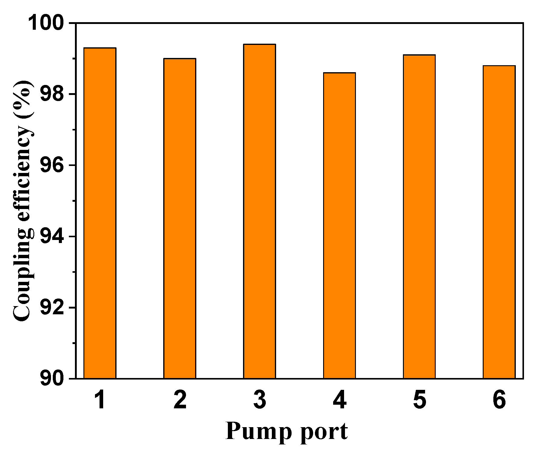
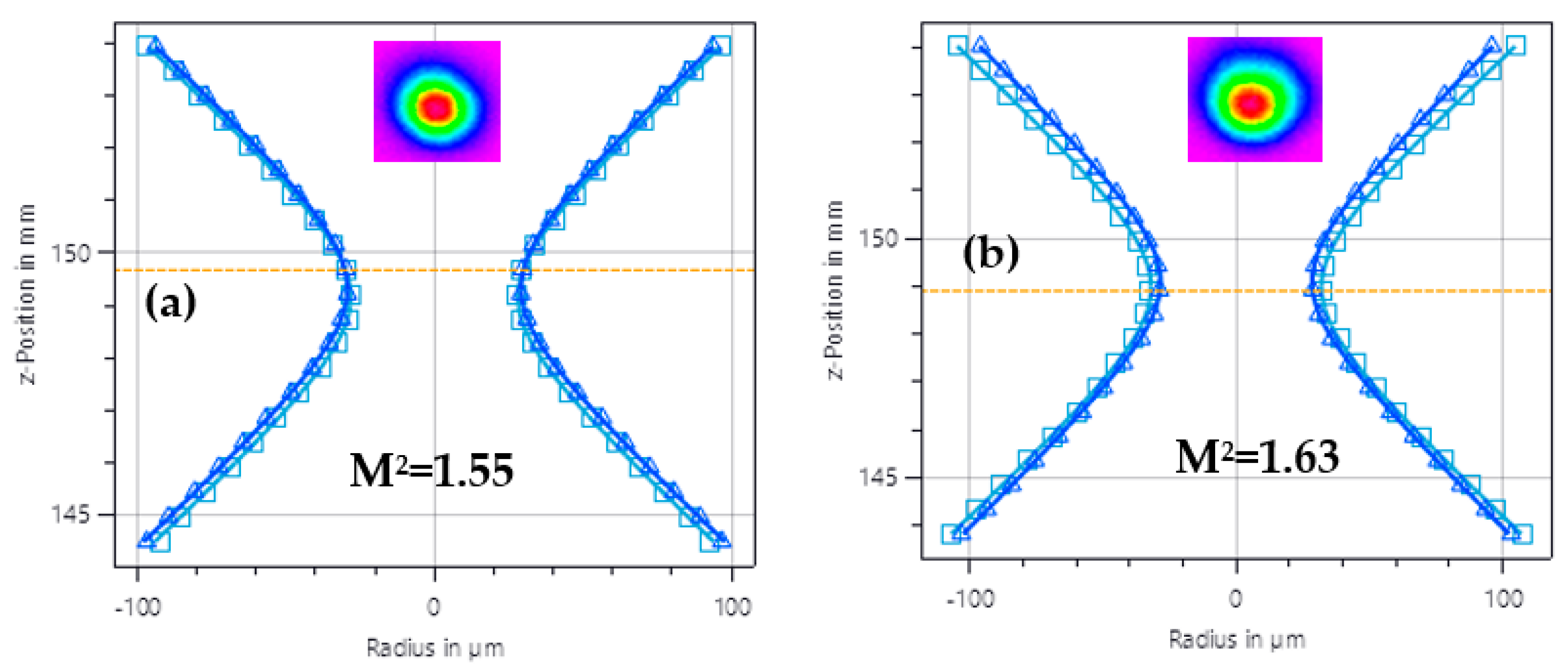
3.2. Tests of the Fabricated Combiner

Firstly, a fiber laser centered at 1018 nm is utilized here to test the pump coupling efficiency for six pump ports of the combiner respectively. The results is depicted in Figure 5: the pump coupling efficiency of all the six pump ports is more than 98.5%, and the average pump power coupling efficiency of the combiner is about 99%. The maximum temperature point in the combiner locates at the coating edge of signal fiber with the coefficient of about 2.9 °C/kW. It should be noted that, the temperature rise coefficient of the same combiner under LD pumping test is more than 10 °C/kW, indicating that the use of higher brightness laser pumping can effectively improve the characteristics of the combiner. Therefore, combiner can operate stably at higher power within the tandem-pumping scheme.
The signal performance of the fabricated combiner is tested with a 3 kW fiber laser. The output pigtail of the fiber laser is 25/400 μm, NA = 0.06/0.46, while the pigtail of the endcap is 48/400 μm, NA = 0.08/0.46. The output patten of the laser is tested through the endcap, whose M2 value is equal to 1.55 and shown in Figure 6a. After passing through the combiner, the M2 value of the signal light is degraded to 1.63 and the measured transmission rate is more than 98%. The degradation ratio is calculate to be only 5% even with such large a core size, which is mainly due to the accurate alignment fusion and non-taper process of the input signal fiber. The good signal transmission characteristic of the combiner can ensure a good performance of the fiber laser.

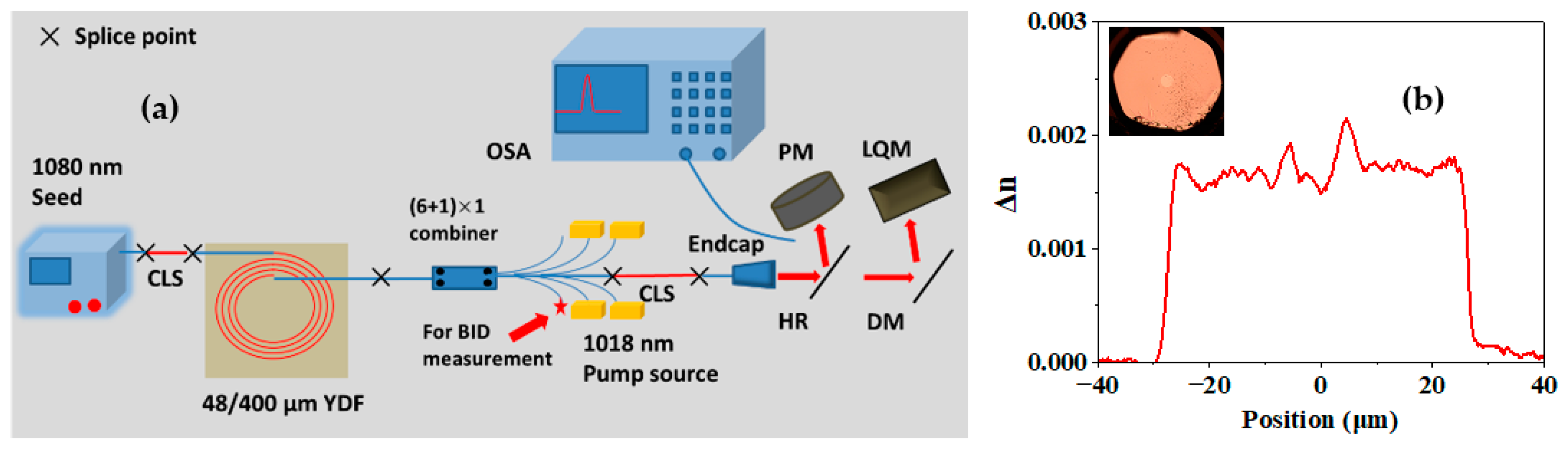
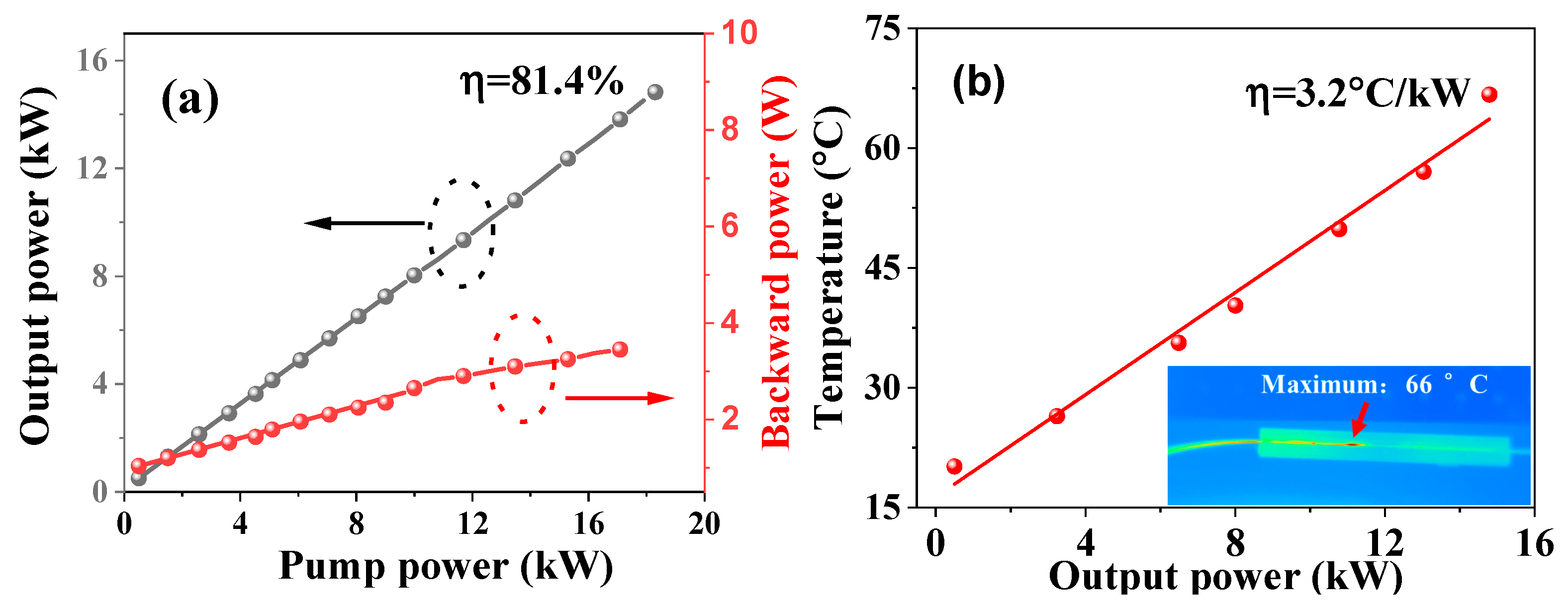
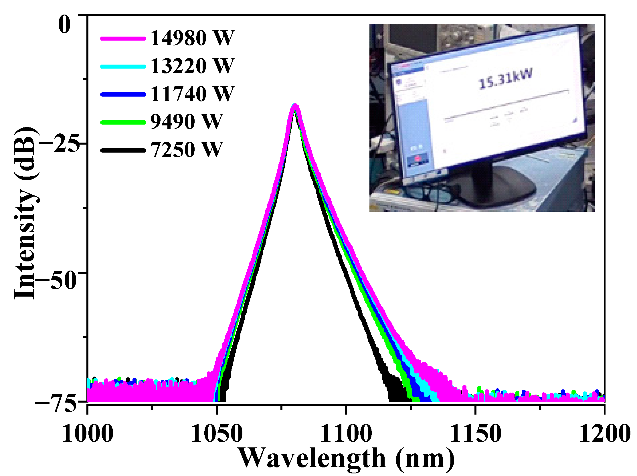
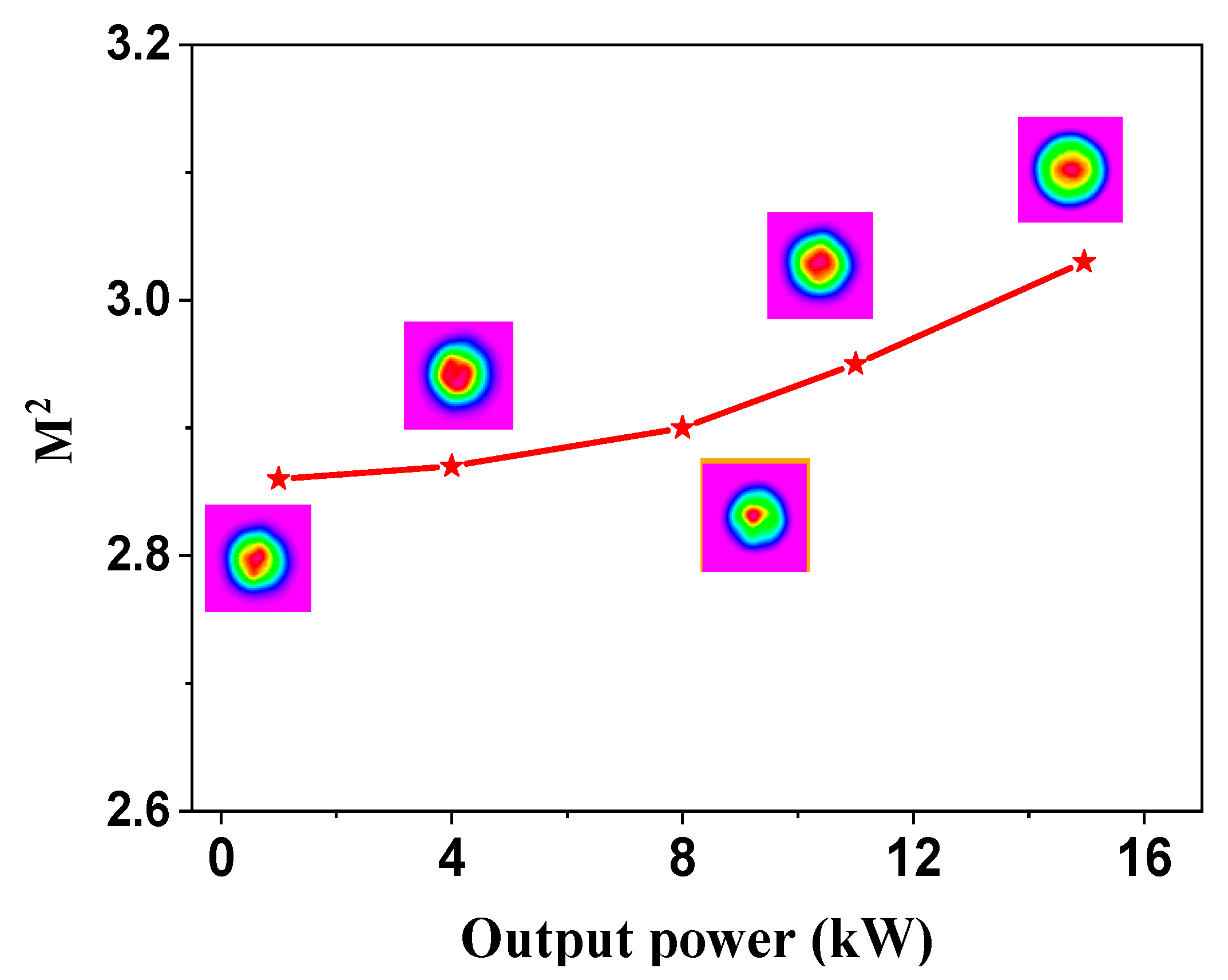
3.3. Fiber Amplifier Setup, Results, and Discussion

As seen in Figure 7a, a counter-directional tandem-pumping amplifier is constructed with the home-made pump/signal combiners. In the amplifier, the seed source is a CW laser which is centered at 1080 nm, and the output fiber pigtail is 20/400 μm. The home-made ytterbium-doped fiber (YDF, 48/400 μm, NA = 0.08/0.46) is used here as the gain fiber, which is placed in the groove of the water-cooling plate. The measured refractive index profile of the Yb-doped fiber is shown in Figure 7b. The pump sources are four 4.5 kW level fiber laser modules centered at 1018 nm, which are spliced with the pump ports of the home-made combiner for counter-directional pumping. The rest two pump ports of the combiner are left for the measurement of the backward power. Two cladding light strippers (CLS) are utilized in the amplifier to remove the residual pump power and protect the seed laser. For the sake of measurement, a endcap coated with antireflection films is spliced with the output pigtail of the CLS. In this experiment, the output power, spectrum, temperature characteristic and beam quality of the system output are measured respectively.
The power and temperature characteristics of the system are measured and shown in Figure 8a,b. The seed power is set as 150 W during the test. From Figure 8a, the output power of the amplifier increases linearly with the rise of the pump power with the slope coefficient of 83.2%. The output power of the system peaks at 14.98 kW when 18.45 kW pump power is injected. It should be noted that there is no apparent power saturation appears, which means that the output power could be further improved with the increase of input pump power. In addition, the power transmitting from the pump pigtail of the combiner increase slightly with the rise of the pump power. When the pump power reaches to 17 kW, the output power from pump pigtail of the combiner is only 3.45 W, corresponding to the BID of about 36.9 dB per leg port. The good backward isolation characteristics of the beam combiner can effectively ensure the safety of the pump source in high power operation. Figure 8b depicts the relationship between the highest temperature in the combiner with the output power. During the test, the combiner is fixed on the water cooling plate by thermal silicone grease and the cooling temperature is set as 20 °C. As can be seen from Figure 8b, the maximum temperature of the combiner increases linearly with the rise of output power. The highest temperature point in the combiner locates at the coating edge of signal fiber which is mainly caused by the leaked pump power from the coating of signal fiber. When the output power reaches to its maximum value, the highest temperature in the combiner increases to 66 °C with the coefficient of 3.2 °C/kW. Combined with the power characteristics of the amplifier and the temperature characteristics of the pump/signal combiner, it can be judged that the output power of the system has the potential to further increase.
The spectra of the amplifier under different output powers are shown in Figure 9, which are recorded by an optical spectrum analyzer (Yokogawa, spectrum covering 600–1700 nm) with the resolution of 0.2 nm. As can be seen from Figure 9, the 3 dB linewidth of the spectrum increases slightly with the increase of the output power and peaks at 3.04 nm when the maximum output power reaches to 15.31 kW. Thanks to the large mode area of the signal fiber and counter-directional pumping structure, there is no apparent Raman line appears in the spectrum, indicating the potential for the further improvement of the output power.
The relationship between the beam quality with the output power is measured by PRIMES LQM system. As shown in Figure 7, the output laser of the system is split by a highly reflectivity mirror (HR, reflectivity ~99.95% @ 45°). The reflected laser from the HR is sent to a power meter (PM), while the transmitted laser is reflected to a M2 analyzer by a dichroic mirror for beam quality measurement. The measurement results are depicted in Figure 10: the M2 value of the amplifier rises slightly with the increase of the output power. When the output power is 1 kW, the M2 value is calculated as 2.88, while the output power reaches to 14.9 kW, the measured M2 value is 3.03. It should be noted that the beam quality degradation of the combiner is tested to be only 5%, and the reason why the M2 value of the amplifier is relatively high may due to the mode field mismatch and fusion quality between the YDF and the passive fiber. In addition, no apparent TMI appears when the amplifier reaches to the maximum output power, suggesting that there is still room for the power improvement.
As discussed above, we have built a fiber amplifier with a record output power of 15 kW by using home-made pump-signal combiner, which effectively proves the rationality of the combiner fabrication method. In addition, since the signal fiber is not tapered and the core consistency is maintained well during the fabrication process, the degradation of the signal beam quality is minimized to about 5%, which is the lowest value among the reported paper. The output power of the amplifier could be further enhanced by adding the co-directional pumping based on the current experimental system.

4. Conclusions

In conclusion, a fabrication method of (6 + 1) × 1 pump/signal combiner with large signal core size and negligible beam quality degradation is firstly introduced here. From the perspective of theoretical analysis, the M2 value is preferable when selecting the feedback parameter for alignment and fusion as it is more sensitive to the change of axial off-set value. In this case, a M2 analyzer is used for precise in-line alignment splicing. The degradation ratio of the signal beam quality in the fabricated combiner is only 5% even with such large a core radius, and the tested coupling efficiency is more than 98% for both pump and signal light. Besides, the home-made pump/signal combiner is utilized in a counter-directional tandem-pumping fiber amplifier with 15.31 kW output power. The temperature rise coefficient of the combiner is tested as 3.2 °C/kW in the amplifier, proving the great potential of this kind of combiner for high power laser applications.

Author Contributions

Conceptualization, Z.L. and Z.C.; methodology, Z.L. and M.F.; validation, H.X. and Z.W.; formal analysis, Z.L.; investigation, Z.L.; resources, Z.C. and J.C.; data curation, Z.C.; writing—original draft preparation, Z.L.; writing—review and editing, Z.C.; supervision, Z.W.; project administration, J.C.; funding acquisition, Z.W. All authors have read and agreed to the published version of the manuscript.

Funding

This work was supported by the Outstanding Youth Science Fund Project of Hunan Province Natural Science Foundation (2019JJ20023); National Natural Science Foundation of China (11974427, 12004431); State Key Laboratory of Pulsed Power Laser Technology (SKL-2020-ZR05).

Data Availability Statement

Not applicable.

Conflicts of Interest

The authors declare no conflict of interest.

References

  1. Qi, Y.; Yang, S.; Wang, J.; Li, L.; Bai, Z.; Wang, Y.; Lv, Z. Recent advance of emerging low-dimensional materials for vector soliton generation in fiber lasers. Mater. Today Phys. 2022, 23, 100622. [Google Scholar] [CrossRef]
  2. Wang, Y.; Chen, G.; Li, J. Development and prospect of high-power doped fibers. High Power Laser Sci. Eng. 2018, 6, e40. [Google Scholar] [CrossRef]
  3. Samson, B.; Carter, A.; Tankala, K. Doped fibres: Rare-earth fibres power up. Nat. Photonics 2011, 5, 466–467. [Google Scholar] [CrossRef]
  4. Shiner, B. The Impact of Fiber Laser Technology on the World Wide Material Processing Market. In CLEO: Applications and Technology; Optica Publishing Group: Washington, DC, USA, 2013. [Google Scholar]
  5. Lin, H.; Xu, L.; Li, C.; Shu, Q.; Chu, Q.; Xie, L.; Guo, C.; Zhao, P.; Li, Z.; Wang, J.; et al. 10.6 kW high-brightness cascade-end-pumped monolithic fiber lasers directly pumped by laser diodes in step-index large mode area double cladding fiber. Results Phys. 2019, 14, 102479. [Google Scholar] [CrossRef]
  6. Chen, H.; Cao, J.; Huang, Z.; Tian, Y.; Pan, Z.; Wang, X.; Chen, J. Experimental Investigations on TMI and IM-FWM in Distributed Side-Pumped Fiber Amplifier. IEEE Photonics J. 2020, 12, 1502413. [Google Scholar] [CrossRef]
  7. Gao, W.; Fan, W.; Ju, P.; Li, G.; Zhang, Y.; He, A.; Gao, Q.; Li, Z. Effective suppression of mode distortion induced by stimulated Raman scattering in high-power fiber amplifiers. High Power Laser Sci. Eng. 2021, 9, e20. [Google Scholar] [CrossRef]
  8. Xiao, H.; Zhou, P.; Wang, X.L.; Guo, S.F.; Xu, X.J. High power 1018 nm monolithic Yb3+-doped fiber laser and amplifier. Laser Phys. Lett. 2012, 9, 748. [Google Scholar] [CrossRef]
  9. Wang, Z.; Yan, P.; Huang, Y.; Tian, J.; Cai, C.; Li, D.; Yi, Y.; Xiao, Q.; Gong, M. An Efficient 4-kW Level Random Fiber Laser Based on a Tandem-Pumping Scheme. IEEE Photonics Technol. Lett. 2019, 31, 817–820. [Google Scholar] [CrossRef]
  10. Lei, C.; Li, Z.; Zhang, H.; Chen, Z.; Hou, J. Taper-fused side pump combiner for all-fiber lasers and amplifiers: A review. Opt. Laser Technol. 2020, 130, 106353. [Google Scholar] [CrossRef]
  11. Lei, C.; Chen, Z.; Gu, Y.; Xiao, H.; Hou, J. Loss mechanism of all-fiber cascaded side pumping combiner. High Power Laser Sci. Eng. 2018, 6, e56. [Google Scholar] [CrossRef] [Green Version]
  12. Xiao, Q.; Yan, P.; Ren, H.; Chen, X.; Gong, M. Pump-signal combiner with large-core signal fiber feed-through for fiber lasers and amplifiers. Appl. Opt. 2013, 52, 409. [Google Scholar] [CrossRef] [PubMed]
  13. Stachowiak, D.; Kaczmarek, P.; Abramski, K.M. Application of self-fabricated passive fiber components in all-fiber high-power laser and amplifiers systems. In Laser Technology 2018: Progress and Applications of Lasers; Romaniuk, R.S., Jabczynski, J.K., Eds.; SPIE: Bellingham, WA, USA, 2018; p. 8. [Google Scholar]
  14. Zou, S.; Chen, H.; Yu, H.; Sun, J.; Zhao, P.; Lin, X. High-efficiency (6 + 1) × 1 pump–signal combiner based on low-deformation and high-precision alignment fabrication. Appl. Phys. B 2017, 123, 288. [Google Scholar] [CrossRef]
  15. Gu, Y.; Lei, C.; Yang, H.; Xiao, H.; Leng, J.; Chen, Z. High-beam-quality signal and pump combiner with large-mode-area fiber for high-power fiber laser and amplifier. Appl. Opt. 2019, 58, 1336. [Google Scholar] [CrossRef] [PubMed]
  16. Liu, Y.; Liu, K.; Yang, Y.; Liu, M.; He, B.; Zhou, J. High power pump and signal combiner for backward pumping structure with two different fused fiber bundle designs by means of pretapered pump fibers. Opt. Express 2021, 29, 13344. [Google Scholar] [CrossRef] [PubMed]
  17. Liu, Y.; Huang, S.; Wu, W.; Xie, L.; Zhang, C.; Li, H.; Li, Y.; Li, Y.; Tao, R.; Lin, H.; et al. 5-kW-Level Bi-Directional High-Efficiency Pump and Signal Combiner with Negligible Beam Quality Degradation. IEEE Photonics J. 2022, 14, 7108806. [Google Scholar] [CrossRef]
Figure 1. The brief diagram of the pump-signal combiner.
Photonics 09 00644 g001
Figure 2. Theoretical relationships between the core off-axis value with the signal transmission rate (a) and the M2 value (b).
Photonics 09 00644 g002
Figure 3. (a) The structure diagram of the seven-hole glass tube; microscopic images of the TFB before (b) and after (c) the central fiber inserted.
Photonics 09 00644 g003
Figure 4. M2-based in-line alignment splicing structure.
Photonics 09 00644 g004
Figure 5. The tests results of the pump coupling efficiency of the pump-signal combiner.
Photonics 09 00644 g005
Figure 6. The M2 value of the signal light before (a) and after (b) transmitting the home-made combiner.
Photonics 09 00644 g006
Figure 7. (a) Experimental setup of the counter-directional tamden-pumping fiber amplifier based on the home-made pump-signal combiner: CLS, cladding light stripper; HR, highly reflective mirror; DM, dichroic mirror; PM, power meter; OSA, optical spectrum analyzer; LQM, beam quality analyzer. (b) The measured refractive index profile of the gain fiber.
Photonics 09 00644 g007
Figure 8. (a) The output power and efficiency results of the amplifier; (b) the temperature results of the amplifier.
Photonics 09 00644 g008
Figure 9. The spectrum of the amplifier at different output power.
Photonics 09 00644 g009
Figure 10. The M2 value of the amplifier at different output power.
Photonics 09 00644 g010
Publisher’s Note: MDPI stays neutral with regard to jurisdictional claims in published maps and institutional affiliations.

