1. Introduction
Due to the advantages of a high transmission rate a large transmission capacity, and spectrum limitation, the free space optical (FSO) communication system [
1,
2], is a popular research technology in application scenarios such as Last-mile technology, free space data backhaul and broadcasting [
3,
4]. However, in the actual atmosphere laser communication link, the transmission of the laser beam in the atmospheric channel can be easily affected by the atmospheric turbulence effect and atmospheric attenuation effect [
5]. Among them, random fluctuations in the amplitude and phase of the received signal caused by atmospheric turbulence [
6] are the main factors leading to the deterioration of the performance of the communication system [
7] and even have a great influence on the reliability of the communication system [
8,
9]. Though adaptive optics [
10], aperture averaging [
11], spatial diversity [
12], and modulation technique [
13] have been used to suppress atmospheric turbulence effect and reduce the duration of fading, their high computational complexity and higher requirements for equipment have significantly increased the complexity and cost of the system [
14,
15,
16]. Channel code technology has been proposed to resist the fading caused by atmospheric turbulence without changing the structure of the transmitter or receiver [
17]. The common channel codes used in FSO communication include the Reed Solomon (RS) code [
18], turbo code [
19], and low-density parity check (LDPC) code [
20], especially, and LDPC has the performance of approaching the Shannon limit [
21]. However, in recent years, another coding scheme has come into the sight of researchers. It is the polar code proposed by Turkish professor Arikan in [
22]. This scheme is the only error-correcting code that has been proved mathematically that reached the Shannon limit in binary discrete memoryless channel (B-DMC). In [
23,
24], the authors investigated the performance of the polar code in the FSO system, and the result of the experiment showed that the polar code had a better error correction performance than the LDPC code in the turbulence channel.
For the construction of polar code, in [
22], Arikan proposed to construct the polar code by the Bhattacharyya parameter, while this method applied to the binary erasure channel (BEC). In order to extend polar codes to continuous output symmetrical channels, the authors in [
25] introduced the density evolution (DE) method. However, a large number of convolution operations are involved in each density calculation, resulting in high computational complexity. To solve this problem, in [
26], the Gaussian approximation (GA) method was proposed to evaluate the reliability of each component channel, which reduced the computational complexity to a linear correlation with code length, but this method was suitable for the additive white Gaussian noise (AWGN) channel. In 2016, Schurch [
27] proposed the universal partial order (UPO) relationship among the sub-channels of polar code, which clearly provided the reliability relationship among some sub-channels. In [
23], the Monte Carlo (MC) method was used to construct polar codes in the FSO system, but this method had a high complexity.
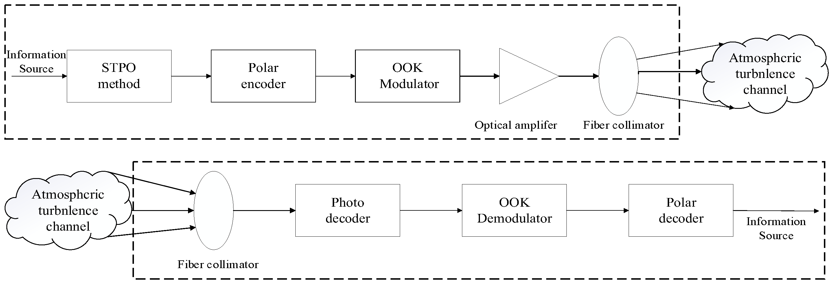
This paper proposes the segmental turbulence partial order (STPO) method to improve the quality of laser communication by using polar code effectively, as well as to reduce the complexity of polar code construction in atmospheric strong turbulence channels. STPO combines the UPO, MC simulation, and polarization weight formula, among which UPO was used to determine the reliability of most component sub-channels, and the reliability of other sub-channels was determined by MC simulation in strong turbulence channels. Then, the polarization weight formula was combined to determine the optimal value of β in different signal-to-noise ratio (SNR) ranges, and the construction of the polar code sequence was completed according to the optimal value of β in the strong turbulence channel. Finally, the error performance of STPO was simulated under different code lengths, code rates, and turbulence intensities, and was compared with the MC method.
3. Atmospheric Turbulence Channel Model
When a laser propagates in an atmospheric turbulent channel, the coherence of the transmitted beam decreases due to atmospheric turbulence, leading to fluctuations in the light intensity and increasing the bit error rate (BER) [
28]. An example is the FSO transceiver located on a high-rise building [
29]. In this paper, intensity modulation/direct detection (IM/DD) was used in an atmospheric laser communication system, and the atmospheric transmission channel was a discrete memory-free channel with AWGN and time-varying gain. Assuming that the signal traversed smoothly in the process of channel transmission, the mathematical model of the channel would be described as follows [
30]:
where
x represents the transmitting signal, and
y is the signal received at the receiver.
I is the intensity fading induced by atmospheric turbulence. The
η means the detector responsivity of the photodetector, and we assumed that
η was equal to one for simplicity.
n is the Gaussian white noise with mean 0 and variance
out of the receiver side. Then the initial value of the message based on OOK modulation can be obtained as follows:
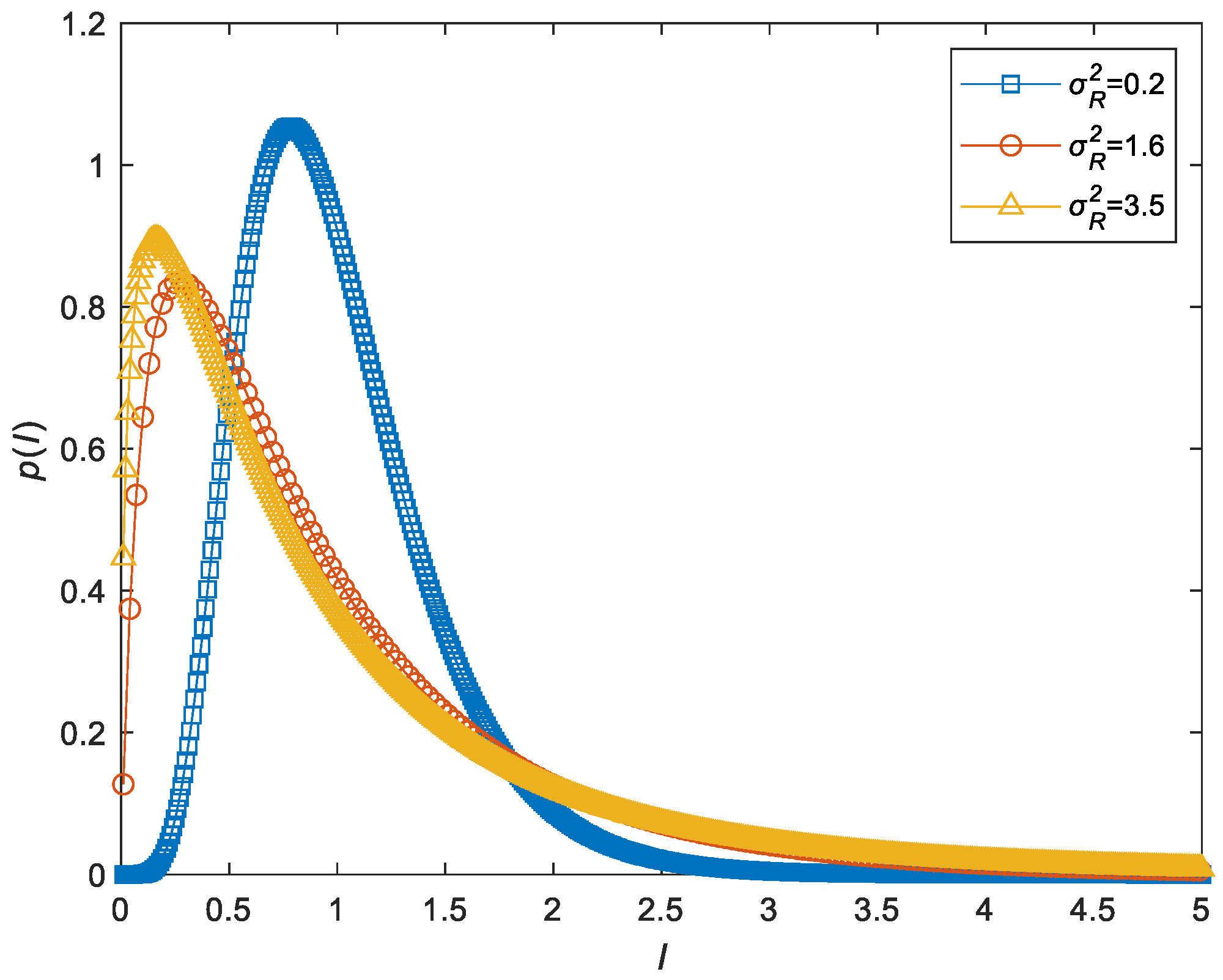
The transmission of optical signals, in atmospheric channels, can be affected by atmospheric turbulence, which can be divided into weak and strong turbulence channels according to the intensity of turbulence. The general consensus is that the light intensity of the flicker follows a log-Normal prior distribution in weak turbulence. When the fluctuations are higher and the turbulence is strong, the distribution of the received signal is Gamma–Gamma distribution. For a relatively broad range of turbulence intensity, the Gamma–Gamma distribution is accepted as a relatively accurate distribution, which can be expressed as [
31]:
where a and b are denoted as the effective numbers of large-scale and small-scale turbulence eddies, respectively.
Γ (·) represents the gamma function, and
K n (·) is the modified Bessel function of the second kind of order n. a and b are related to atmospheric conditions, which are given by:
where
is the Rytov variance, which represents irradiance fluctuations associated with atmospheric turbulence, given by [
32]:
where
denotes the wave number, λ represents the wavelength.
L = 1 km is the transmission distance, and
is the refractive index function structure constant of the turbulence atmosphere. When
, the turbulence is weak. Otherwise, the turbulence is strong [
33].
Figure 2 shows the probability density function of the distribution of the Gamma–Gamma model for different turbulence intensities. From the figure, it can be seen that as the turbulence increases, the curve deviates from the mean value of the light intensity and has a longer trailing edge, which means that the distribution is wider. This shows that the system performance becomes more unstable as the turbulence intensity becomes larger, which is consistent with the actual atmospheric turbulence channel variation. In the simulation experiments, the optical signal received at the receiver was affected by the turbulence randomly generated according to the model.
4. Construction Method for the Polar Code
The atmospheric turbulence channel environment changes due to the turbulence effect. When using the MC method to construct the polar code, a large number of simulated codewords are required to calculate the reliability of each sub-channel. UPO is a universal order of reliability over a part of bit positions for polar code. These orders are “universal” in the sense that they are applicable to any channel, but they are insufficient to define a full order of the whole sequence covering all N bit positions. Therefore, UPO is unreliable when used to construct polar codes in a specific channel. To solve the above problems, the STPO method was proposed by combining UPO with MC in the turbulence channel.
STPO has the basic characters of UPO, and the rules for evaluating channel reliability are as follows [
27]:
When the code length is N, for any two sub-channels , their relative orders with respect to their reliability can be determined with the following three conditions:
If the binary representations of the two channels differ by one digit, then the channel with a digit of 1 is more reliable than the channel with a digit of 0;
If the binary representations of the two channels differ by two digits (they may not be adjacent), then from left to right, the channel with the number 10 is more reliable than the channel with the number 01;
Conditions 1 and 2 can be satisfied repeatedly or simultaneously to determine channel reliability.
To be able to obtain the sub-channel reliability relationship intuitively, this paper proposes a corollary that the binary representation of the channel satisfies that the two adjacent numbers are not both 1, i.e., (The subscript indicates the conversion of the value to binary). Then the channel reliability satisfies , and they are proved as follows:
When the length of code
N = 16, suppose
, then
,
can be expressed as follows:
When , i.e., , then ,,, satisfy that the two adjacent numbers are not both 1, so can be divided into 0 and 01 combinations of the form. By condition 2, the reliability relationship is (The subscript indicates the conversion of the value to decimal), and the reliability relationship is by condition 1, this proves that this inference is valid.
Using this corollary, the reliability relationship for some of the channels can be derived, with the ratios shown in
Table 1.
It can be seen that as the code length increases, the proportion of sub-channel reliability relations obtained by this inference decreases, but at a code length of 32. The reliability relation of more than 30% can still be obtained at a code length of 32, which reduces the complexity of the sequence construction.
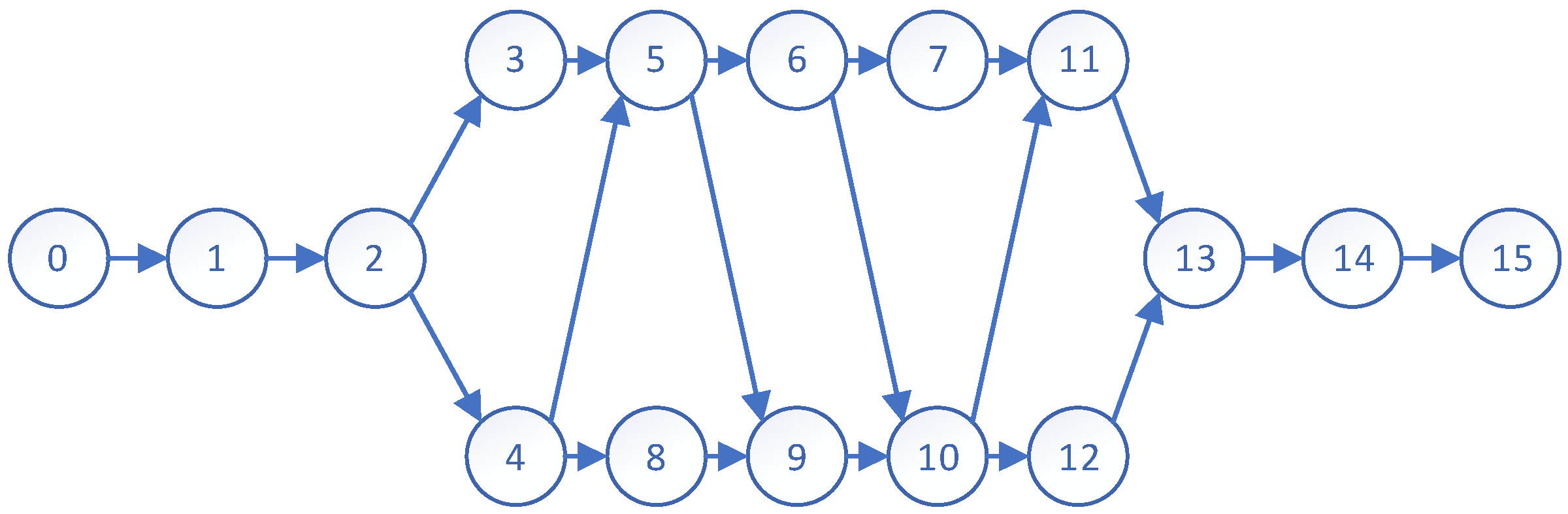
Based on the above properties and inferences, STPO can give the reliability sequence of some sub-channels, and the sub-channel reliability sequence can be represented by the Haas diagram. As
Figure 3 shows the Haas diagram for code length
N of 16, the sub-channel reliability increases sequentially from left to right, and we can obtain the reliability relationship of sub-channels 3 and 5 according to condition 2 but cannot give the reliability of sub-channels 3 and 4.
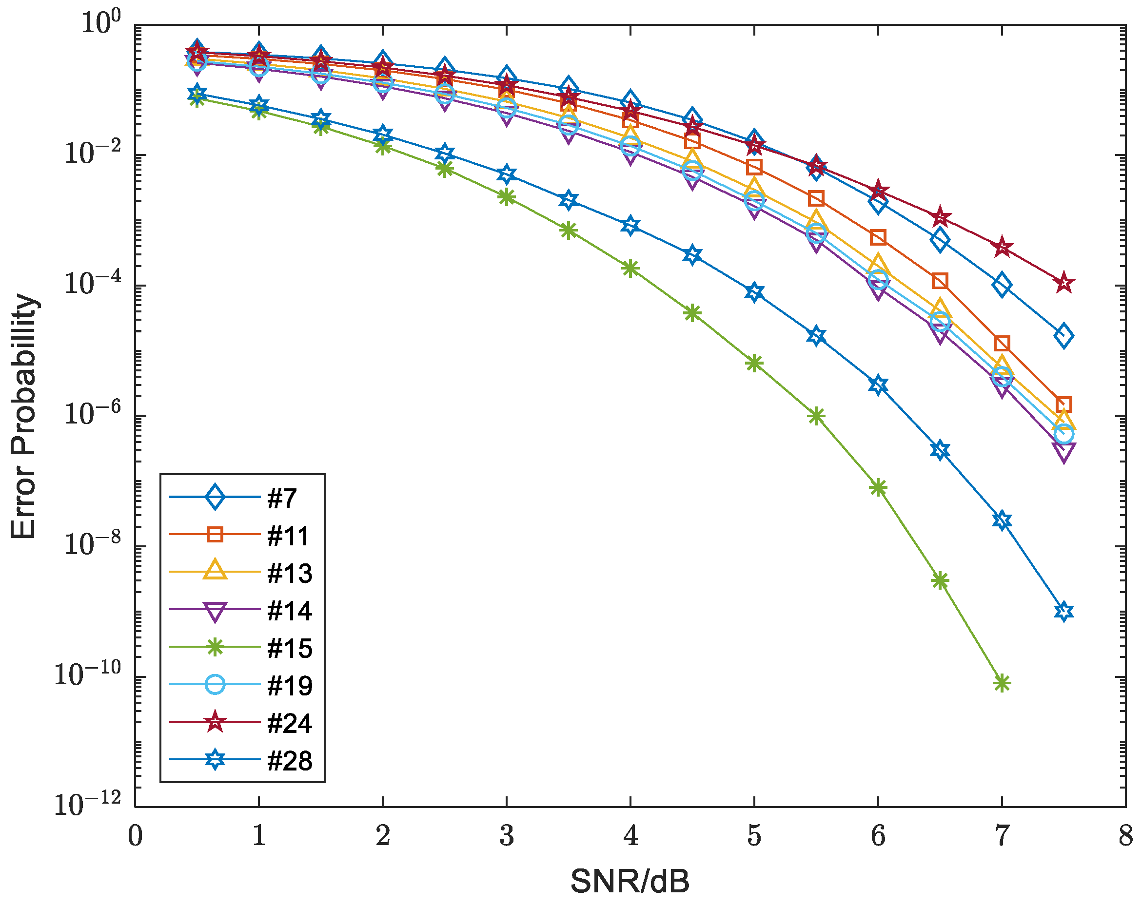
From
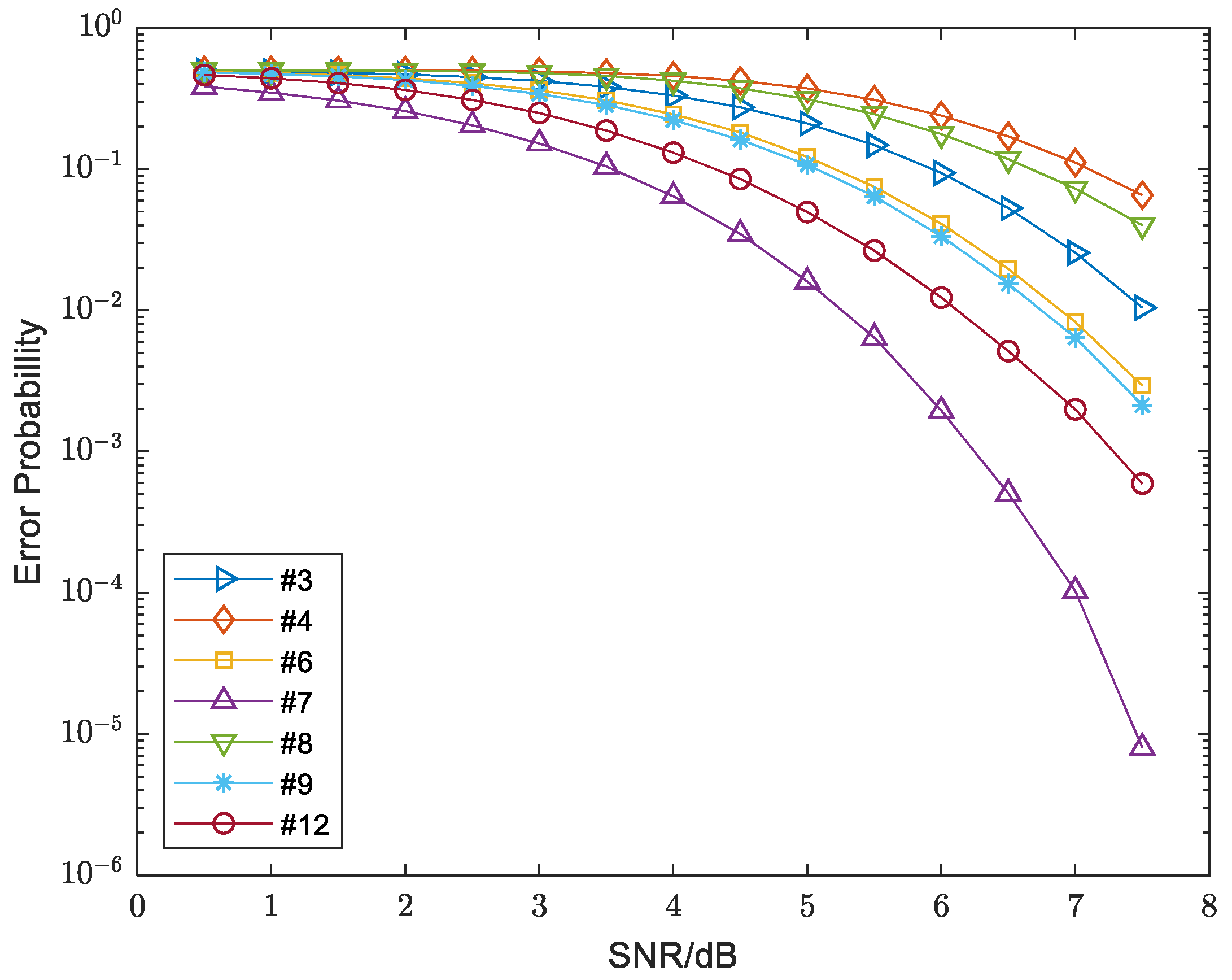
Figure 3, when the code length is 16, the relationship among sub-channels (3,4), (3,8), (6,9), and (7,12) is uncertain. In this paper, a strong turbulence channel with turbulence intensity
was selected, and a polar code sequence with
N = 16 was constructed by MC.
Figure 4 shows the error probability curves of all sub-channels with the increase in SNR. In the strong turbulence channel, sub-channel 3 was more reliable than sub-channel 4 and sub-channel 8 for all the interested SNR values. For the error probability, sub-channel 6 was higher than that of sub-channel 9. Moreover, sub-channel 7 had a better performance than sub-channel 12 in terms of sub-channel reliability. Therefore, when the code length was 16, the polar code was constructed as a single chain by the STPO method.
Polarization weight (PW) is one of the methods that can be used to evaluate the reliability of the polar sub-channel. In this paper, the polarization weight formula was used to evaluate the reliability of sub-channel in strong turbulence channels. The Formula shows as [
34]:
where
,
N represents code length, and
represents the reliability of
i-th sub-channel. Higher
represents a more reliable sub-channel. For the
i-th sub-channel, its channel serial number
i can be described as
in binary representation. β means base for decimal extension, which can represent any real. Take the code length
N = 16 as an example, which shows as:
Polarization weight is used to directly represent the reliability of each sub-channel, but the
β value is different in different channels. Therefore, a suitable
β value was determined to construct polar code in strong turbulence channel in this paper. When
N = 16, the
β value met the reliability relationship of the sub-channel pair (3,4) (3,8) (6,9) (7,12):
According to the set of inequalities of (8), the range of
β values was calculated and shown in
Table 2:
According to
Table 2, when
, a value within this range was sufficient to construct a polar code sequence of
N = 16, but a 16-bit code length could not satisfy the FSO system for information transmission. When
N = 32, the pair of sub-channels to be determined increased by (7, 24) (11, 24) (13, 24) (14, 19) (15, 28). The turbulent channel of
was still selected, MC was adopted for the simulation, and the error probability curve is shown in
Figure 5.
According to the error probability curve of five groups of sub-channels shown in
Figure 5, it can be seen that the relationship among (11, 24) (13, 24) (14, 19) (15, 28) four groups of sub-channels was relatively clear. When SNR was less than 5.25 dB, the error probability of sub-channel 7 was greater than sub-channel 24. With the increase in SNR, the error probability of subchannel 7 was gradually exceeded by subchannel 24. At this time, sub-channel 7 was selected to transmit data to obtain a lower BER.
When SNR < 5.25 dB, the reliability relationship among sub-channel pairs (7, 24) (11, 24) (13, 24) (14, 19) (15, 28) was obtained from
Figure 5, and the
β value was satisfied:
According to (9), the value range of
β is shown in
Table 3.
Combining
Table 2 with
Table 3, the value range of
β could be obtained when SNR < 5.25 dB. When
N = 32,
. When STPO constructed the polar code, any value of
β was taken within this range, and the construction of the polar code sequence was completed by combining with (6).
When SNR > 5.25 dB, according to
Figure 5, the reliability relationship between sub-channel 7 and 24 changed, and the error probability of sub-channel 24 was greater than that of sub-channel 7. At this time,
was satisfied. According to (6),
β < 1.1787 was obtained, and combined with the reliability relationship of other sub-channel pairs in
Table 3,
was obtained.
In order to use the value of
β in the construction of polar code with a longer code length, a more accurate value of
β was needed. When the code length was extended to 64 bits, 10 groups of uncertain sub-channels needed to be obtained according to UPO. After statistics, the number of uncertain sub-channel pairs is shown in
Table 4.
From
Table 4, as the code length increased, the number of sub-channels whose reliability relationship needed to be determined increased exponentially. When the code length was 1024, the number of sub-channels that needed to be determined increased to about 390, and the 1024-bit polar code had met most of the communication requirements, and there it was unnecessary to further expand the code length. For different code lengths, through the MC simulation, the relationship between uncertain sub-channel pairs was obtained, and the SNR was obtained at the point where the relationship between the sub-channels pair error probability changed.
Table 5 shows the mean SNR (M-SNR) of the error probability change point at different code lengths.
Through M-SNR, the value range of β was divided into two parts: SNR was less than M-SNR, and SNR was larger than M-SNR.
Table 6 shows the β value range when SNR was less than M-SNR and the β value range when SNR was greater than M-SNR in different code lengths.
From
Table 5 and
Table 6, when the code length was 1024, the range of
β is selected with SNR = 5 dB as the dividing point. When SNR < 5 dB, then
. When SNR > 5 dB, then
.
The accuracy of the traditional MC method is related to the number of simulations. In order to ensure a high accuracy, it usually requires at least 100,000 simulation times to ensure the accuracy of . Each simulation requires a polar code encoding and decoding operation. The asymptotic complexity of polar code encoding and decoding is . So, the complexity of the MC method is , and the is the number of simulations. STPO method is used to construct polar code by combining UPO with MC. Through the UPO, the reliability relationship of some sub-channels can be determined, then the MC simulation is performed on the sub-channel pairs whose reliability relationship cannot be determined, and finally, the reliability of the sub-channels is evaluated by the PW. It is different from the traditional MC method which needs to calculate the reliability of each sub-channel online. It obtains the reliability relationship of each sub-channel in a turbulent intensity interval by offline simulation. It is versatile and can construct polar code directly according to the PW which is obtained by offline simulation. Polar code is constructed by PW linear complexity , so the complexity of the STOP method for constructing the polar code is . It has a lower coding complexity than the traditional MC method.
5. Simulation Analysis of Polar Code Construction
STPO was used to construct polar code by combining UPO with MC. Based on inheriting the general properties of UPO, Monte Carlo was introduced into the strong turbulence channel to compare and analyze the sub-channels whose reliability cannot be determined by UPO. In order to verify the reliability of STOP in constructing polar code sequence in FSO strong turbulence channel, we conducted relevant simulation experiments in the system model which was introduced in Part 2, and the system parameters are shown in
Table 7. Then MC and STPO were used to construct polar code, respectively, in the MATLAB simulation environment. When SNR < 5 dB,
β value was set to 1.1892, and when SNR > 5 dB,
β value was set to 1.1727. Successive cancellation (SC) decoding was selected as the decoding method for the simulation experiment.
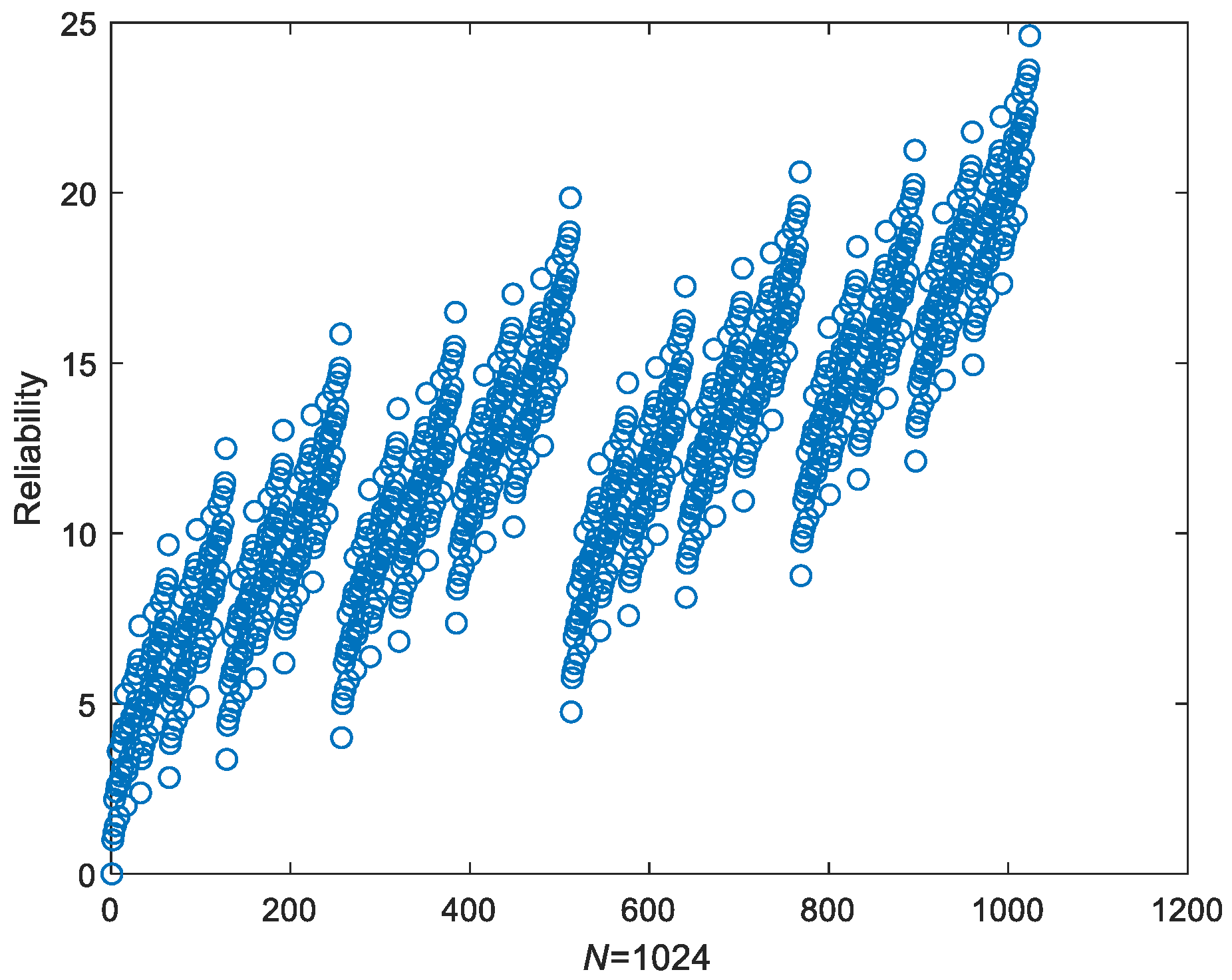
When the code length was 1024 as shown in
Figure 6, the reliability of each sub-channel was given by the STPO structure polar code. When constructing polar code with STPO, sub-channels with a high reliability are selected to carry information bits, and other sub-channels carry frozen bits to complete the construction of the polar code, thus saving a lot of system resources.
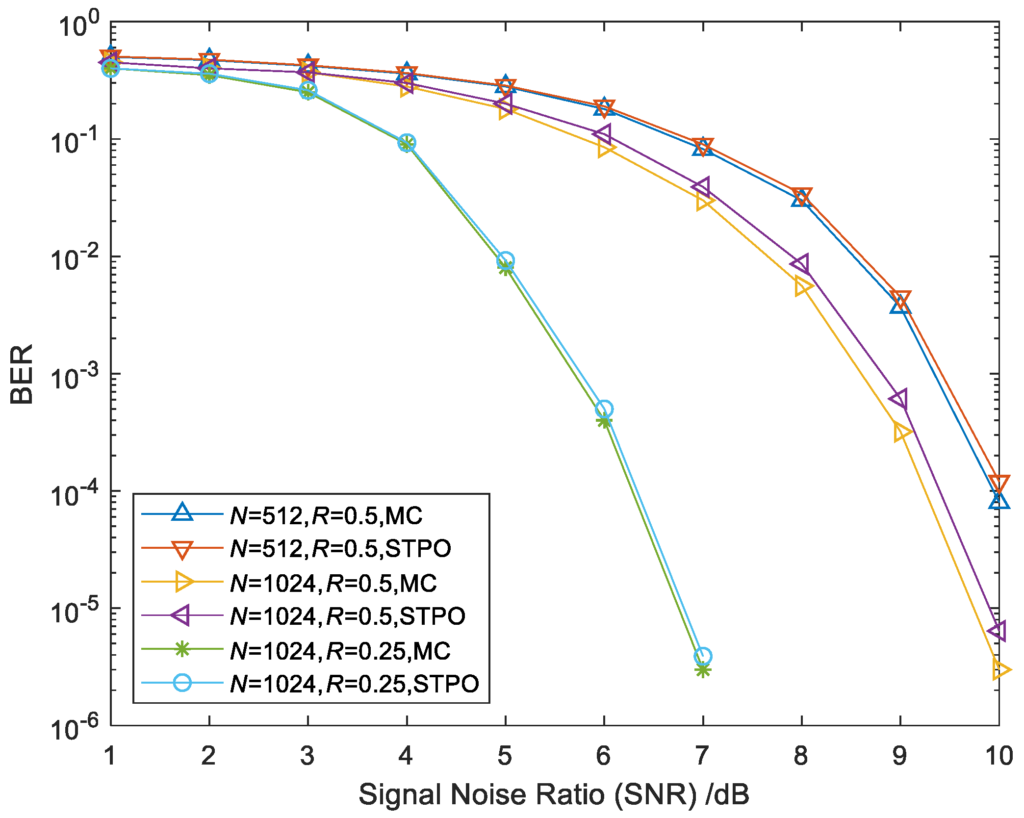
The BER of the polar code constructed by STPO and MC is shown with different code lengths and different code rates in
Figure 7. It can be seen from
Figure 7 that when the code length was 512 and the code rate was 0.5, the polar code constructed by STPO had the same BER in low SNR and produced a loss of about 0.03 dB in high SNR, compared with that under the MC method. When the code length increased to 1024 and the code rate was 0.5, STPO still had the same error performance as MC in low SNR, but the loss in high SNR increased to a 0.17 dB loss when BER was 10
−4. When the code rate was reduced to 0.25, the length was 1024, and the BER of STPO was almost the same as that of MC. Therefore, STPO had an error performance similar to MC with a low bit rate and short code length.
When STPO was used to construct polar code, the error performance was improved when the bit length increased and the bit rate decreased. When BER was 10−4, the code rate was selected as 0.5; if the code length increased from 512 to 1024, there was a gain of about 0.7 dB; when the code length was 1024, the code rate decreased from 0.5 to 0.25, and there was a gain of about 3 dB. Therefore, in actual optical communication systems, considering the best error performance, the bit rate can be appropriately reduced.
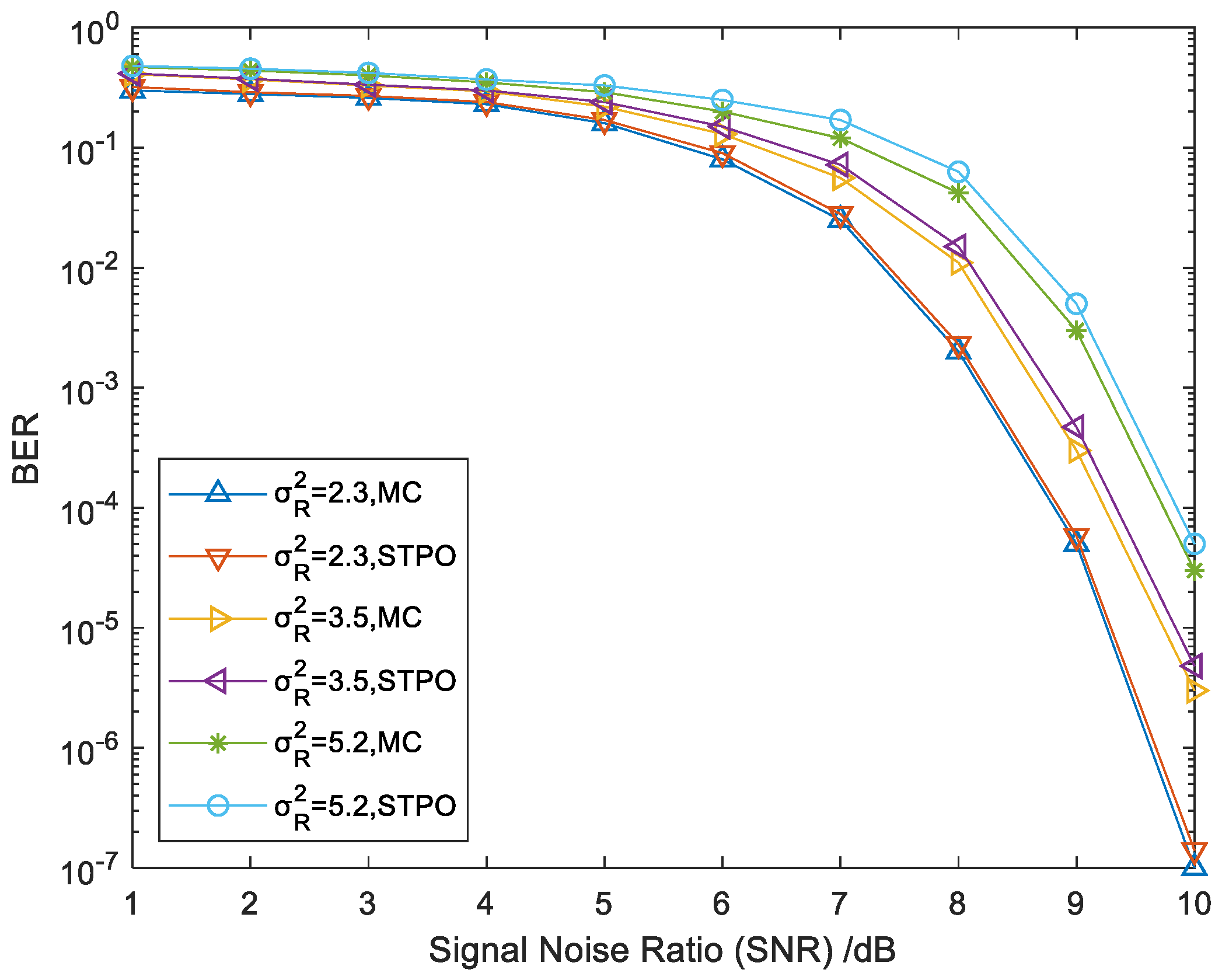
In the FSO system, turbulence intensity is an important factor that affects the error code performance. In a strong turbulence channel, the turbulence intensity has a relatively large change. Therefore, atmospheric turbulence has a significant impact on the reliability relationship of the polarized sub-channel. In order to further prove the feasibility of STPO in strong turbulence channels, considering that the different effects of different degrees of turbulence intensity on communication performance are different,
Figure 8 shows that the length was 1024, the code rate was 0.5, and SC decoding was adopted at different turbulence intensities and the performance of constructing polar code with STPO and MC was compared. From
Figure 8, we can see that these two construction methods generated almost the same BER in low SNR. Moreover, in high SNR, when turbulence intensity was
, two construction methods still had similar error performances. When turbulence intensity was
, BER was 10
−4, STPO was compared with MC, and a loss of about 0.05 dB was produced, which was nearly the same in the condition that
. Therefore, it is feasible for STPO to be used in FSO to construct polar code in strong turbulence, and it had a better performance at a lower turbulence intensity.
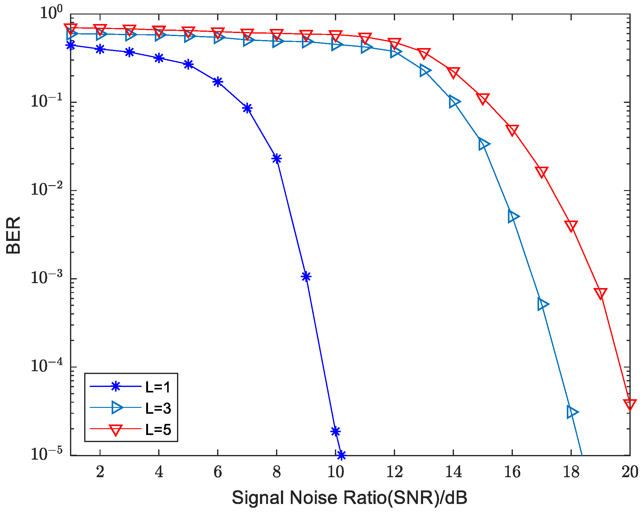
Based on the above simulation results and analysis it can be seen that the STOP and MC methods had similar performances. The system BER curves of the STOP method at different transmission distances are given in
Figure 9. It can be seen from the figure that the system performance decreased as the transmission distance increased. There was a significant decrease in the system performance when the distance increased from 1 km to 3 km, while the system performance did not decrease significantly when the transmission distance increased from 3 km to 5 km. This is because as the distance continued to increase, the flicker of the received optical signal at the receiver side entered a saturation state. Although the communication performance decreased with increasing distance, we can see from the figure that we could improve the communication performance by appropriately increasing the SNR.
STPO was used to construct polar code in an offline operation mode, in which a small number of calculations were required in actual polar code construction, and STPO had an error performance similar to MC in a strong turbulence channel. The application of STPO in the strong turbulence channel greatly improved the transmission performance of the FSO system and had important practical significance for the practical application of the FSO system.


