1. Introduction
Over the last few decades, innovations in optical components, subsystems, systems, and networks have made it possible to meet the growing demands of networks, resulting from the high bandwidth applications required by end users. Today’s 40 to 80 channel optical communication systems with a transmission speed of 10 Gb/s have difficulty meeting the demands of high-capacity transmission systems. Next-generation optical communication systems can operate at a data rate of 40 to 100 Gb/s per channel for long-distance transmissions [
1].
Data transmission is also expected in the future due to the rapidly growing use of high-speed online services and broadband applications, such as ultra high-definition television (UHDTV), teleconferencing, etc. This trend continues to push broadband communication infrastructure closer to higher end-user speeds, higher capacity, and longer ranges.
Successful commercialization of DWDM (Dense Wavelength Division Multiplexing) systems was standardized by the International Telecommunication Union (ITU-T) [
2] as the core network infrastructure. This allows services to be managed using multiple different wavelengths of light when transmitted through the same optical fibers, with OTN (Optical Transport Network) clients being able to occupy up to the full wavelength [
3].
In addition, it allows the network to transmit the vast amounts of data needed for many current and future communications services and applications. DWDM technology was first deployed as a point-to-point system in which the optical fiber was used as a direct replacement, at that time in the field of transmission media of the dominant copper line. This stage of development of DWDM systems was characterized by the fact that the switching and data processing took place in electrical form, and thus the optical signal transmitted by the optical fiber was converted at each point of the network (switch or router) into an electrical signal. A key breakthrough in the field of optical communication networks occurred in the late 1990s and the beginning of the new millennium. The main reason was the first deployment of a completely new DWDM system and other technologies, which we eventually call the second generation of optical networks, in which security and recovery functions were moved to the optical part of the network [
1].
With the dynamic growth of companies, one of the necessary factors is the development of communication. More interesting communication network is turning toward fully optical networks, in which the transmitted signal passes transparently without optoelectronic conversion. Significant advances in optical networks have meant new DWDM technology, which allows the transmission of multiple carrier optical waves over a single optical fiber. Due to its low transmission attenuation loss, C-band and L-band is usually selected to use in the DWDM system [
4].
The design methods are used for network planning as well as later capacity planning during operation. At present, it is very important that the provider offers its services with a certain level of quality. The most common qualitative indicator is the Q factor or BER. In general, operating models should be used to determine these parameters. Based on the parameters, the network provider then decides whether network requirements are sufficient [
5]. Implementation of DWDM networks into already built optical networks is very simple. Because in this case it is only necessary to innovate the transmission systems, while the fibers remain unchanged. For this reason, DWDM technology is currently commonly used.
The ultimate goal is to design fully transparent optical networks, as these networks offer the most economical solution with transparency in bit rate, signal format, and protocol [
6].
A typical DWDM system and network covers the entire network space consisting of the building’s own networks, access, and metropolitan, long-distance, and ultra-long-distance networks. The distances covered by these networks range from a few meters for home networks to long-distance optical links, such as transoceanic cables, which can range from several hundred kilometers to several thousand kilometers.
However, the new generation of optical communication systems will already operate at a transmission speed of 40–100 Gb/s. The demand for multimedia is growing exponentially, so DWDM systems need to be adapted to meet these demands. To maximize the potential of DWDM networks, it is necessary to analyze the properties of the transmission medium and optimize all system parameters [
7]. The optical channel is usually most affected by the signal shape, dispersive and nonlinear characteristics of the transmission medium. Simultaneous transmission of several optical channels at a high transmission speed is particularly problematic. These degradation effects are detrimental in multichannel optical transmission, especially at higher data rates in the presence of nonlinear phenomena. Therefore, the goal is to make the best use of the transmission capacity of the system with the lowest signal degradation [
8].
Our goal is to improve DWDM transmission properties based on amplification techniques. We expect better BER parameters when deploying a larger number of EDFA amplifiers in a DWDM scheme, which is also a benefit of our work. We also see the benefit in the design of DWDM schemes with SOA amplifiers, as there is a lack of studies on this design.
2. Full Optical Networks
The large increase in data transmission has resulted in increasing bandwidth requirements for the physical transport layer. Fully optical DWDM networks (see
Figure 1) are used to increase the transmission capacity of optical transmission media [
9]. At present, DWDM networks are still deployed in backbone networks. The aim is to build these networks with electro-optical conversion in individual nodes. The signal passes from the source to all nodes of the DWDM network in optical form. The switching speeds of the electronic components fail to keep pace with the transmission speeds offered by fully optical signal processing. Networks based on optical signal processing are called fully optical networks [
10]. To implement such networks, we need frequency and time division multiplexing, demultiplexing, rewriting or wavelength conversion. They serve to reduce phenomenon, thus achieving more efficient use of the optical spectrum. A demultiplexer is an important part of the WDM systems allowing separating wavelengths from one input into several outputs. A slot waveguide demultiplexer can be used to increase the number of wavelengths that can be demultiplexed without changing the dimensions of the device. The goal is low wavelength while maintaining low sensitivity to changes in operating wavelengths and other sensitivity expressions, the overall size is not such that there are changes in operating wavelengths.
2.1. Dense Wavelength Division Multiplexing
DWDM networks are optical networks that use the principle of wavelength division multiplexing (WDM), which allows one optical fiber to transmit several optical carriers, each at a different wavelength. The advantage is that the transmission at each wavelength can take place with a different transmission rate and modulation. At the same time, analog and digital optical signals can be transmitted. The number of wavelengths that can be transmitted simultaneously to a single optical fiber depends on the physical properties of the fiber itself. Furthermore, from the optical elements that allow the transmission of multiple wavelengths to a single fiber, as well as their selection and the current research in the field of DWDM technology.
Optical physical properties are used when using optical fibers. As a result, accompanying phenomena arise in optical transmissions. Some emerging phenomena and properties are used in data transmission, other phenomena and properties need to be eliminated in certain ways and with certain techniques. High light output, for example due to the use of amplifiers, can cause non-linear phenomena [
11].
DWDM provides an indisputable increase in the capacity of long-distance optical networks, in other words, with the implementation of DWDM, the price per transmitted bit is significantly reduced in long-distance transmissions (50 km and more). However, the quality and reliability of such transmission is becoming a significant limitation. Most DWDM networks available today use intensity modulation and direct detection.
2.2. Optical Amplifier
The growth of the capacity of communication networks has been made possible by the development of new optoelectronic technologies, which can be used to use the huge bandwidth of the optical fiber. Today, systems are in operation that operate at high baud rates [
12]. Optical technology is the dominant carrier of global information. It is also a focal point in the implementation of future networks that will have the required capabilities and characteristics. These features include virtually unlimited bandwidth for the transmission of communication services of almost any kind and full transparency, which allows for the upgrade of terminals in terms of capacity and flexible channel routing. The optical amplifier has made many advances in optical networks [
13].
Optical amplifiers can be divided into two classes: Optical Fiber Amplifiers (OFA) and Semiconductor Optical Amplifiers (SOA) (
Table 1) [
14]. The first type tends to dominate conventional system applications, such as in-line reinforcement, used to compensate for fiber losses. However, due to advances in optical semiconductor manufacturing techniques and device design, SOA has shown great promise for use in the development of optical communication networks [
15]. It can be used as a general amplifier, but also has many functional applications, including optical switching and wavelength conversion. These functions, where optical signals are not converted into an electrical area, are required in transparent optical networks [
16].
Modern optical amplifiers represent a more efficient and economically acceptable solution that provides high optical power gain regardless of the characteristics of the input optical signal. Optical amplifiers most often work on the same principle as lasers, which means on the principle of stimulated emission. In terms of the parameters of the optical amplifier, the most important gain is when pumping optical power into the amplifier. The gain is influenced by many factors, but especially by the material from which the medium is made in the optical amplifier, the intensity of the light beam at the input and its wavelength [
17]. Under ideal conditions, the gain can be mathematically described by the equation as:
where
g0 represents the highest gain value, ω denotes the magnitude of the incident signal,
ω0 represents the transient frequency,
P is the optical power of the signal being amplified, Parameter
T2 denotes the dipole relaxation time value and
Ps denotes the saturation power which depends on the amplifier medium used [
18,
19].
3. Related Work
In this section, we compared our results with similar published systems. We tried to find DWDM systems that have comparable transmission speed, number of channels, and similar amplifiers. In total, we found five papers [
20,
21,
22,
23,
24]. Other publications described systems with two or more different parameters so the comparison of their properties with our proposal does not provide useful findings.
Lee, Yang, and Chou [
20] demonstrated a wavelength-division-multiplexed passive optical network (WDM-PON) scheme based on novel reconfigurable optical amplifiers ROA (Raman optical amplifier). The measured switching characteristics of the ROA
3 constructed with a 2 × 2 crossbar optical switch and a fourport reversible optical circulator (OC) and a conventional EDFA can meet the requirements of most network management and surveillance. Ref. [
20] also included simulation results for the optimized EDFA whose length of EDF is 7.5 m long with a 1480 nm pump laser of 40-channel WDM-PON 10 Gb/s. The curves are reported for CH1 (190.8 THz, 1571.24 nm) and CH20 (192.7 THz, 1555.75 nm) and numerical results are presented in
Table 2 [
20].
Tan and Iqbal [
21] compared PM-64 QAM 11-channel WDM signals over 75.6 km of single-mode fiber (SMF) using EDFA, discrete Raman, hybrid Raman/EDFA, and first-order or second-order (dual-order) distributed Raman amplifiers. Their results demonstrate that the second-order Raman scheme had flatter signal power profiles along the fiber, the lowest Amplified Spontaneous Emission (ASE) noise level, and the highest OSNR [
21]. BER curves of 64 QAM 11-channel WDM. The result of system [
21] is in
Table 3.
Zulherman, Fahmi, and others [
22] demonstrated Raman Optical Amplifier (ROA) to overcome the attenuation in the nonlinear system. The proposed system consists of eight channels with 20 nm channel spacing. Length of optical fiber was 60 km. They tested launch power from −8 to 6 dBm. The result for optical power 0 dBm is shown in
Table 4.
Gupta and Meena [
23] in 2022 demonstrated a 16-channel 10 Gb/s DWDM system using EDFA amplifier with dispersion compensating fiber. The proposed system consists of 180 km SMF fiber and 12 km DCF fiber. EDFA gain was 10–30 dB and gain of photodetector was 2 dBm. Their achieved results for pre-compensation scheme are shown in
Table 5.
Kheraliya and Kumar [
24] in 2018 proposed a 32-channel WDM system where they studied the parameters of optical amplifiers. They achieved very interesting results (
Table 6). The simulation model consists of a 32-channel 10 Gb/s WDM system.
Our work contains an improvement compared to the first-mentioned system [
20] in the transmission speed, which we set at 40 Gb/s also the same improvement is in fourth system [
23]. Compared to the second system’s [
21] number of channels, we set our model at at 32 channels. In the third system [
22] our improvement is in transmission length. The improvement compared to the fourth system [
23] is the number of channels. The fifth system [
24] that we are comparing with has a lower transmission speed than our system. More about our system is described in
Section 4.
4. Experimental Setup
When designing DWDM systems, it is necessary to select a suitable type of optical amplifier. The magnitude of the signal intensity bound to the optical fiber has a significant effect on the generation of nonlinear phenomena, and thus significantly limits the range of the DWDM system [
25]. This part is devoted to the design and selection of key parameters of EDFA, SOA, and ROA optical amplifiers. At the end of this section, a comparison of the achieved BER values using different types of optical amplifiers in our prototype DWDM system is also performed. We used the OptiSystem program for our experiment.
The OptiSystem from Optiwave is suitable for simulation of optical communication systems. It is possible to design, test, and optimize various designs of optical connections and systems from analog to fully digital. The program also has its limitations, it does not contain all the measurement blocks that would be suitable for determining parameters for our needs. We use basic parameters to compare our proposed systems.
All optical amplifiers were simulated in schemes with constant parameters that are shown in (
Table 7).
4.1. Erbium Doped Fiber
The typical EDFA gain per distance at an Erbium Doped Fiber (EDF) length of about 10 m is 20–30 dB. However, the maximum achievable power at the amplifier output is limited by pump power, type of fiber and length of fiber.
Depending on the EDFA configuration, the EDF length can be up to 30 m, because a continuous wave laser (CW Laser) can be used as the light source for near 1550 nm pumps, the pump is then combined with an information signal using a WDM coupler. An important factor that significantly affects the efficiency of EDFA is the choice of light source. In practice, we use light sources with wavelengths of 1550 nm in forward mode (
Figure 2) [
26]. In the forward pumping mode, the wavelength of the pump propagates in the same direction as the transmitted signal (
Figure 3). In practice, it is very common to use forward, backward, and bidirectional EDFA configuration.
Our design (
Table 8) consists of four 50 km optical single-mode fibers (ITU-T.G.652 [
27]), four DCF fibers 10 km long to suppress nonlinear phenomena. The total length of the optic fiber is 240 km. The scheme (
Figure 3) uses six EDFA amplifiers with a gain of 5 dB and the noise figure is set to 4 dB and one EDFA amplifier with gain 10 dB and noise figure is 4 dB. Amplifiers are arranged between optical fibers. In the receiving part are 32 optical receivers and BER analyzers. We reached BER values for the first channel 4.229 × 10
−14 and for the 20th channel 3.609 × 10
−3. All results are in
Table 9.
Compared to the results from [
21], our system achieves better BER with EDFA amplifier over longer fiber optic distances. Their system achieved BER 1 × 10
−9 for both examined channels. Our system achieved this for the first channel BER 4.229 × 10
−14 and 20th channel 3.6 × 10
−3. There is a BER improvement on the first channel. The overall improvement in the scheme is in transmission length.
The optical spectrum
Figure 4 helps to visualize the wavelengths of the individual channels and the power they achieve on the receiving side.
4.2. Raman Optical Amplifier
The amplification of the Raman optical amplifier (ROA) arises from the emission of photons from lower energy states to higher energy states due to Raman scattering, in which photons of incident light interact with atoms or molecules from the optical medium or with vibrational and rotational states of the optical medium. This emission is not spontaneous, and the optical medium needs to be excited by a light source. ROA is usable in the region of 1300–1600 nm and in this region the gain typically reaches up to 15 dB. The usable ROA bandwidth is 48 nm. Currently, ROA is very popular and, together with EDFA, is used for long-distance transmissions in DWDM systems. Its advantage over EDFA is that the pump source provides more flexibility in terms of wavelength selection —the most used wavelengths are: 1440 nm, 1500 nm, and 1540 nm. A big advantage is its relatively simple implementation into the existing infrastructure. The amplification is performed directly in the transmission fiber and it is not necessary to use a doped fiber. Therefore, ROA is referred to as a distributed optical amplifier. For ROA, we distinguish between two configurations: with a forward pump source (
Figure 5) and with a reverse pump source. The ROA gain does not depend on the position of the pump source. The disadvantage of ROA is the possible fluctuations in the light level of the pump source [
28]. This can cause uneven amplification when transmitting multiple wavelengths in a WDM system, and thus cause fluctuations in amplitude and jitter of the amplified signal.
Our design (
Figure 6) consists of 32 channel laser array of two 50 km optical single-mode fibers and two 10 km long DCF fibers. The total length of the optic fiber is 120 km. The scheme use one ROA amplifier with a length of 1 km. Amplifiers are arranged between optical fibers. In the receiving part are 32 optical receivers and BER analyzers. We reached BER values for the first channel 5.166 × 10
−11 and for the 20th channel 5.676 × 10
−8. All results are shown in
Table 10.
The optical spectrum of the channels using the ROA amplifier is shown
Figure 7. As we can see, the first channel is at wavelength 1.552 µm and power is −16 dBm. The 20th channel length is 1.539 µm and power is −17 dBm.
4.3. Semiconductor Amplifier
The SOA amplifier (
Figure 8) is powered by electricity. The active area in the device supplies the input signal with a gain through stimulated emission. The output signal is accompanied by noise. This additional noise, Amplified Spontaneous Emission (ASE), is created by the amplification process [
29]. SOAs are sensitive to polarization. This is due to many factors, including waveguide structure and material. Polarization sensitivity can be improved using square waveguides.
SOA gain is affected by the input signal power and internal noise generated by the amplification process. As the input signal power increases, the gain decreases. This gain saturation can cause significant signal distortion. It can also limit the gain achievable when SOAs are used as multichannel amplifiers in WDM systems [
29,
30].
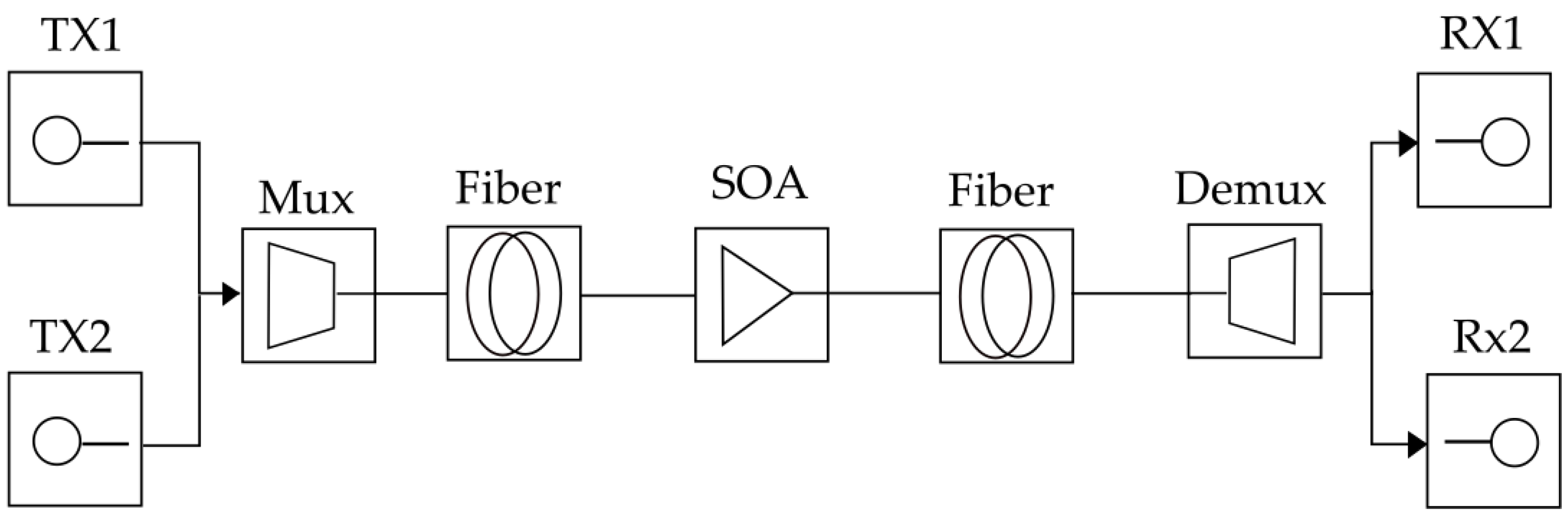
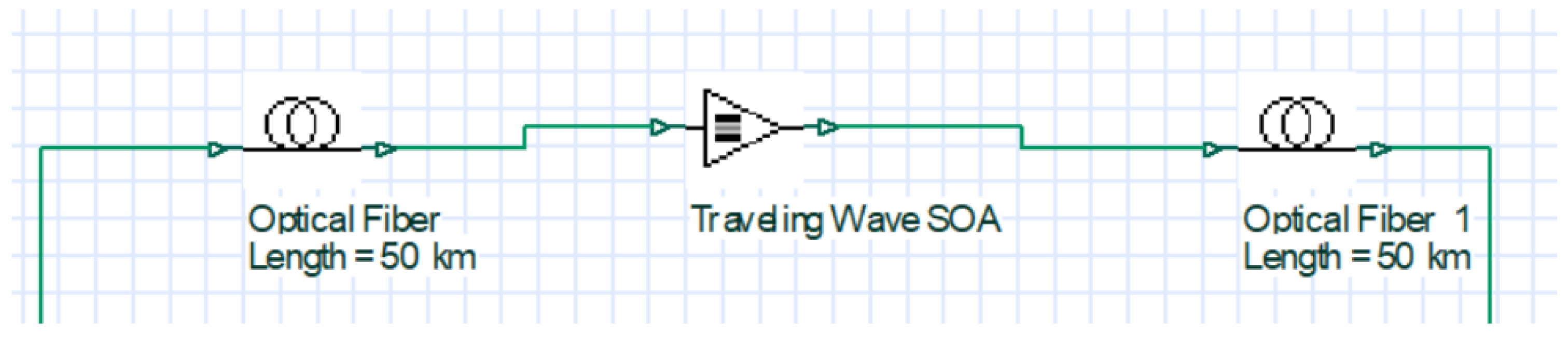
Our design (
Figure 9) consists of a 32-channel laser array of two 50 km optical single-mode fibers. The total length of the optic fiber is 100 km. The scheme use one SOA amplifier with a length of 0.0003 m. The amplifiers are arranged between optical fibers. In the receiving part, there are 32 optical receivers and BER analyzers. We reached BER values for the first channel 3.651 × 10
−3 and for the 20th channel 5.565 × 10
−3. All results are shown in
Table 11.
As we can see, the BER parameters in our system with a semiconductor amplifier per 100 km of optical path are worse than in the proposed EDFA 32-channel system. For the first channel SOA system, it is 3.522e × 10
−3 and for the first channel EDFA it is 4.229 × 10
−14. The optical spectrum is shown in
Figure 10.
Another simulation is focused on acquiring the relation between output power and log of BER (
Figure 11) with considering the nonlinear effect called SRS (Simulated Raman Scattering). The input power was set to a constant value (0 dBm at 193.1 THz).
5. Discussion
For the networks described in
Section 4, we perform simulations to demonstrate the traditional use of DWDM amplifiers for 40 Gb/s transmission. Each channel has 240 km of SMF and seven optical amplifiers for the case of EDFA simulation. The individual tables show the results for several simulated channels. These simulations were repeated 10 times and the values for the first and twentieth channels are averaged.
In addition, we used a ROA amplifier for a system with a transmission speed of 40 Gb/s and a total fiber life of 70 km. An average of the simulated values was generated from 10 experiments. Finally, we simulated an SOA amplifier with a total length of 100 km. The average of the results is in
Table 9. We achieved improvement in all simulated schemes compared to colleagues who published similar simulations.
The best results in our schemes are achieved by the EDFA amplifiers, where BER values are of the order of 1 × 10⁻¹⁴. For example, channel 5 has reached minimal BER 1.284 × 10⁻¹¹. Best result in ROA scheme is reached in channel 5 (BER 9.641 × 10⁻¹³). The SOA amplifier is not as efficient for our scheme as the other two amplifiers. SOA values for minimal BER are on the order of 1 × 10⁻³. With further optimization of SOA, we should be able to achieve better results.
We see the potential in improving the EDFA scheme to achieve better BER values under the same set conditions, by adjusting the number of pieces and the power of the amplifiers. The results show the correct handling of DWDM schemes with higher bit rate and lower BER. There are quite a few tested DWDM schemes with SOA. Therefore, there is no comparison of SOA with other schemes in this work. This article can also be used for future comparison of SOA amplifiers with our established scheme.
This article is used to compare amplifiers in our proposed schemes. It has not reached the goal of designing a system for future practical deployment. From our previous research, we designed a system with a larger number of amplifiers, where we achieved BER improvement at the expense of the economic point of view. Although there is no planning to put the system into practice, it will help many researchers in future DWDM network designs.
6. Conclusions
In conclusion, this paper demonstrates a new design of multiple EDFA optical amplifiers in a single transmission path. It compares individual types of optical amplifiers in a DWDM system. Additionally, it dealt with the topic of amplifiers in DWDM systems. We investigated the effect of EDFA, ROA, and SOA on the transmission quality in a 32-channel DWDM system with 40 Gb/s transmission speed per channel. After a brief introduction to the area and an overview of relevant approaches, a new scheme was proposed in
Section 4. It combines the latest knowledge about DWDM systems and their properties from our previous work. We focused on the approximation of optical networks, specifically DWDM and optical amplifiers. In
Section 3, we focused on related work, which has a similar focus as our research. At the end of the article, we compared output power and log of BER for all three types of amplifiers.
Comparing different types of amplifiers in our DWDM systems can help us to further increase transmission speed with lower BER.
In the future, our plan is to optimize high-capacity DWDM systems with optical amplifiers for better BER values. We would like to increase number of channels to 64 or more, achieving favorable transmission speed. Since current common transmission speeds are around 40 Gb/s [
29], we plan to reach speeds of at least 100 Gb/s or more.
Our long time goal is evaluation of 128 channel 100 Gb/s DWDM system for long distances by computing BER values and plotting eye diagrams. We would like to apply the knowledge obtained from simulations in this paper in design phase of these systems.


