Article

Numerical Demonstration of the Transmission of Low Frequency Fluctuation Dynamics Generated by a Semiconductor Laser with Optical Feedback

School of Science and Technology of Information Science, Dalian Maritime University, Dalian 116026, China
*
Author to whom correspondence should be addressed.
Photonics 2022, 9(7), 483; https://doi.org/10.3390/photonics9070483
Submission received: 8 June 2022 / Revised: 22 June 2022 / Accepted: 8 July 2022 / Published: 11 July 2022
(This article belongs to the Special Issue Semiconductor Lasers: Science and Applications)

Abstract

:
In this paper, the transmission mechanism of the spike information embedded in the low frequency fluctuation (LFF) dynamic in a cascaded laser system is numerically demonstrated. In the cascaded laser system, the LFF waveform is first generated by a drive laser with optical feedback and is then injected into a response laser. The range of crucial system parameters that can make the response laser generate the LFF dynamic is studied, and the effect of parameter mismatch on the transmission of LFF dynamics is explored through a method of symbolic time-series analysis and the index, such as the spike rate and the cross-correlation coefficient. The results show that the mismatch of the pump current has a more significant influence on the transmission of LFF waveforms than that of the internal physical parameter of the laser, such as the linewidth enhancement factor. Moreover, increasing the injection strength can enhance the robustness of LFF transmission. As spikes of the LFF dynamic generated by lasers with optical feedback is similar to the spike of neurons, the results of this paper can help understanding the information transporting and processing inside the photonic neurons.

1. Introduction

Semiconductor lasers with optical feedback can generate various nonlinear physical phenomena and can be applied in secure communication, random number generation, lidar, comprehensive sensing, and reservoir computing, etc. [1,2,3,4,5,6,7]. Moreover, the low frequency fluctuation (LFF) dynamic induced by the optical feedback architecture has been found to be a type of excitable behavior [8], which can be exploited for photonic neurons [9,10,11,12,13] and neuromorphic computations such as pattern recognition, logic operations, and calculations [14,15,16,17,18,19]. In the LFF region, the laser output displays abrupt and irregular power dropouts, and this type of spike has been proven to be similar to the spikes generated by biological neuron models such as the FitzHugh–Nagumo (FHN) model [20]. As the optical feedback scheme can avoid the optical isolator and is suitable for photonic integrated circuits (PICs), lasers with optical feedback are a promising candidate in the field of photonic neural computing.
There have already been studies on LFF dynamics in the literature. A. Aragoneses et al. implemented numerical simulations and experimental studies for the output signal of a directly modulated optical feedback semiconductor laser with optical feedback and investigated the external locking mechanism of the external modulation signal on the laser output signal through timing analysis (event analysis) of the output waveform [21]. They also proposed a minimal model to simulate the output of an optical feedback laser [22]. T. Sorrentino et al. investigated the pulse rate and pulse correlation of the output pulses of a laser with optical feedback [23]. Moreover, the periodic locking mechanism of the external periodic signal on the output of the optical feedback laser has been studied [24,25]. According to [26], the study of photonic neurons will evolve to the transmission of spikes in a photonic neural system composed of multiple photonic neurons. However, there are few studies on the transmission of various spike information embedded in LFF dynamics. Therefore, in this paper, the transmission of the LFF waveform in a cascaded laser system consisting of a laser with optical feedback and another laser is studied, and the effects of various system parameters on the output of the system are analyzed and discussed.
The reminder of this paper is organized as follows. In Section 2, the system structure, theory model, and tools for describing the system output characteristics are introduced. In Section 3, the effect of various system parameters on the transmission of LFF dynamics is studied and analyzed. The discussion of the results and conclusions are provided in Section 4.

2. Materials and Methods

2.1. System Architecture

Figure 1 shows the schematic diagram of a cascaded laser system composed of two semiconductor lasers. One laser is subjected to optical feedback and it is named the drive laser (LD-1 in Figure 1). The output of the drive laser is injected into the other laser, which is called the response laser (LD-2 in Figure 1).
The Lang–Kobayashi (LK) model is always used to describe semiconductor lasers with optical feedback, and the rate equations are as follows:
d E D ( t ) d t = 1 2 ( 1 + i α D ) { G [ N D ( t ) N 0 ] 1 + ε | E D ( t ) | 2 1 τ p } E D ( t ) + κ D E D ( t τ ) e i ω τ + 2 β s p ξ ,
d N D ( t ) d t = I D q V 1 τ n N D ( t ) G [ N D ( t ) N 0 ] 1 + ε | E D ( t ) | 2 | E D ( t ) | 2 ,
d E R ( t ) d t = 1 2 ( 1 + i α R ) { G [ N R ( t ) N 0 ] 1 + ε | E R ( t ) | 2 1 τ p } E R ( t ) + κ R E D ( t ) e i ω t + 2 β s p ξ ,
d N R ( t ) d t = I R q V 1 τ n N R ( t ) G [ N R ( t ) N 0 ] 1 + ε | E R ( t ) | 2 | E R ( t ) | 2 ,
where ED(t) and ER(t) in Equations (1) and (3) represent the slowly varying electric field amplitude of the drive laser and response laser, respectively, and ND(t) and NR(t) in Equations (2) and (4) denote the carrier density of two lasers, respectively. κD is the feedback strength of the drive laser, and κR is the injection strength of the response laser. ID and IR denote the pump current of two lasers, respectively, and αD and αR represent the linewidth enhancement factor of the drive laser and response laser, respectively. βsp = 10−4 ns−1 is the noise strength, and ξ is a Gaussian distribution with zero mean and unit variance. The physical meaning and values of the remaining parameters are shown in Table 1.
As is well-known, with different system parameters, such as the pump current ID and the feedback strength κD, the semiconductor laser with optical feedback can generate rich dynamic behaviors. When ID is 15 mA, which is near the threshold (14.6 mA in our model) and κD is small (10 ns−1 for instance), the output of the laser exhibits random oscillations and belongs to the coherent collapse, as shown in Figure 2a. Moreover, when ID is near the threshold and κD is relatively large (50 ns−1 for instance), the output of the laser contains abrupt power dropouts, which have certain probabilistic characteristics, as shown in Figure 2b. At this time, the output of the laser belongs to the LFF waveform. In addition, when ID is higher than the threshold current (22 mA for instance), the output of the laser belongs to the coherent collapse, no matter whether the feedback strength κD is big or small, as shown in Figure 2c,d. Therefore, to generate the LFF dynamic, the pump current should be near the threshold, and the feedback strength should be relatively large. In the rest of this paper, ID is set to be 15 mA and κD is set to be 50 ns−1.

2.2. Tools

We analyzed the timing information of the spike sequence through an ordinal time-series analysis [22]. Firstly, a pulse sequence with a length of N is divided into N-D vectors of length D, as shown in Equation (5). Δt(i) is the time interval of pulse i, and t(i) is the time at which pulse i occurs.
Δ t ( i ) = t ( i ) t ( i 1 ) .
Based on the relative length of Δt(i), each time interval is associated with a word composed of D symbols. For example, when D = 2, two types of words exist. Δt(i) < Δt(i + 1) gives the word “01” and Δt(i) > Δt(i + 1) gives the word “10”. Table 2 shows ordinal patterns for D = 3. Then, by counting the frequency of occurrence of the different words, their probabilities are computed, as shown in Equation (6),
P 1 = n 1 j = 1 6 n j ,
where P1 is the probability of word 012, n1 is the number of the word 012, and the rest of the words are calculated similarly.
This symbolic transformation has the drawback that it disregards the information about the precise duration of the inter-spike intervals (ISIs), but it has the advantage that it keeps the information about the temporal correlations among them, i.e., correlations in the timing of the optical spikes. Figure 3a shows the words extracted from the output of the drive laser. When the feedback strength increases from 50 ns−1 to 100 ns−1, the probabilities of all of the words occur certain degrees of oscillations. In particular, when the feedback strength was within the region from 70 ns−1 to 80 ns−1, the probabilities of words “012” (blue line) and “201” (light blue line) was lower than the average probability (1/6), while the probabilities of other words were higher than 1/6. According to [27], this phenomenon indicates that the laser may has an encoding effect on the feedback strength.
In addition, the pulse rate can be used to analyze the output waveform of the system, and it can be calculated by Equation (7), where s is the total number of ISIs.
r a t e = s i = 1 s Δ t ( i ) .
Figure 3b reflects the effect of the feedback strength on the pulse rate. The figure shows that when the feedback strength is enhanced, the average pulse rate of the drive laser tends to decrease, indicating that the greater the feedback strength the longer the pulse interval is. This also means that the LFF dynamic has an encoding effect on the feedback strength [27].
Meanwhile, the performance of the LFF transmission is evaluated by the correlation coefficient between the output waveforms of the drive and response laser, and it can be defined as
C C = [ P D ( t ) P D ( t ) ] [ P R ( t ) P R ( t ) ] | [ P D ( t ) P D ( t ) ] 2 | | [ P R ( t ) P R ( t ) ] 2 | ,
where PD(t) and PR(t) represent the power of the driver laser and response laser, respectively, and · represents the time average. When CC = 1, the output waveforms of both lasers are identical, and CC is less than 1 if there is a deviation between the output of the lasers.

3. Results

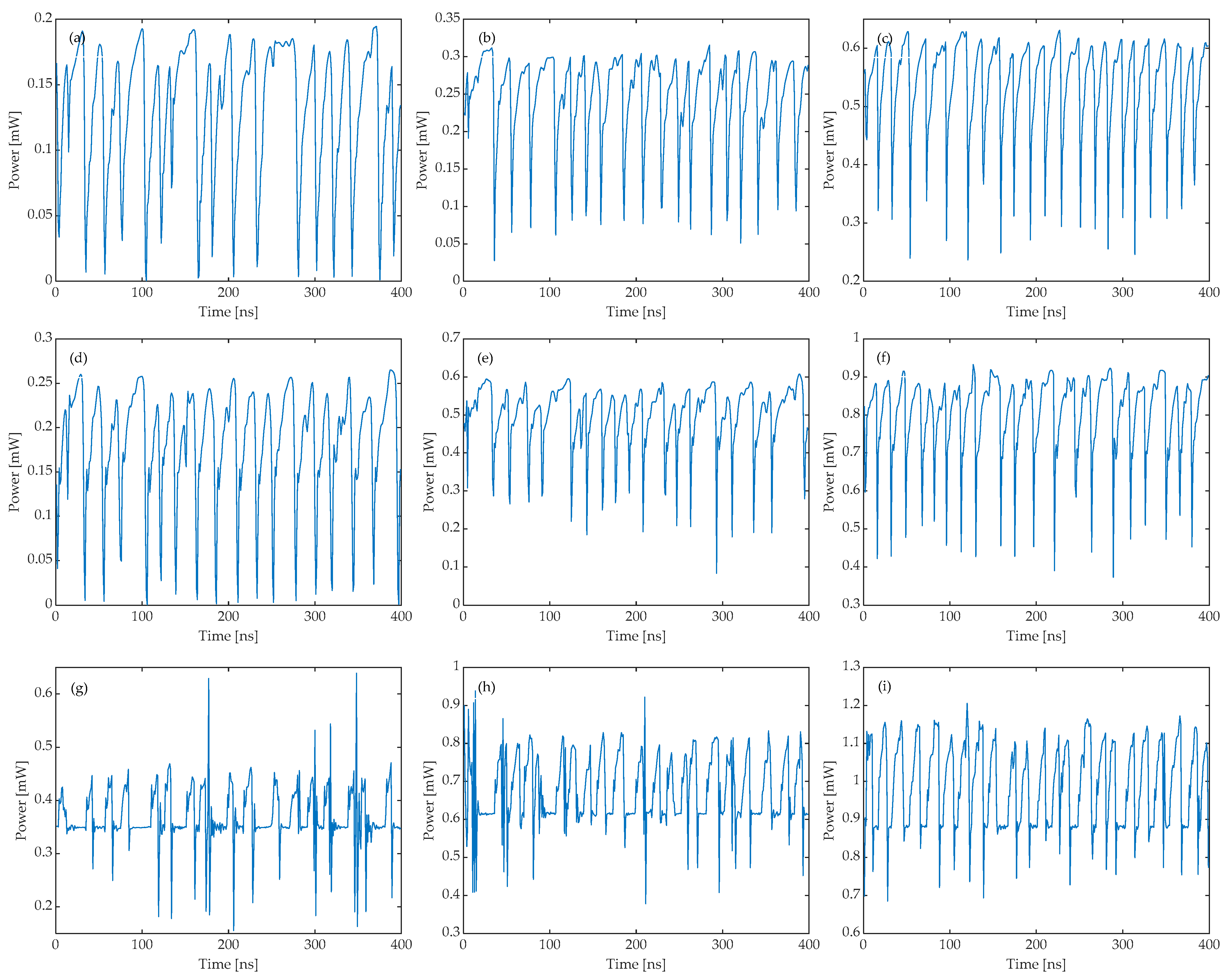
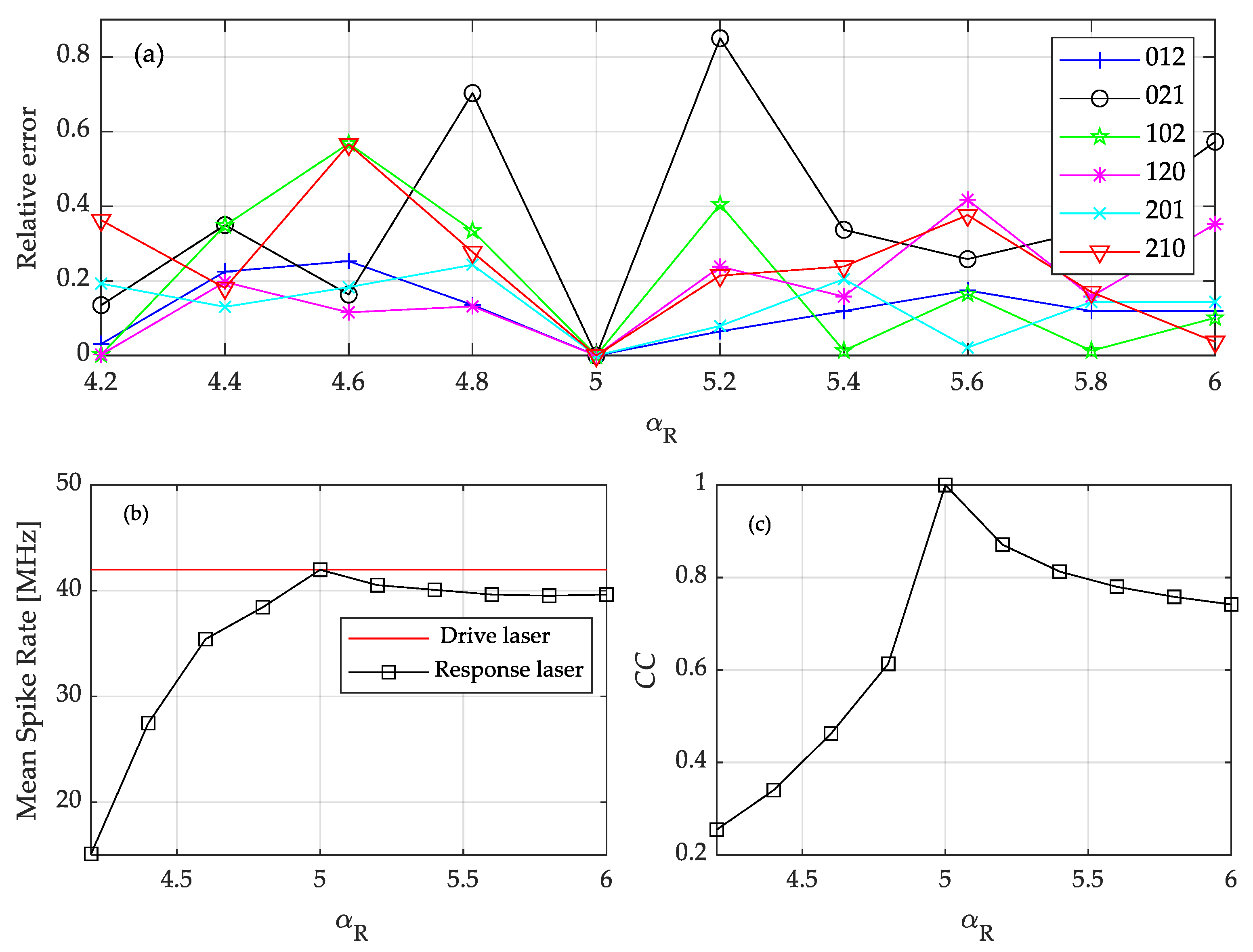
3.1. Effect of System Parameters on the Output of the Response Laser

Firstly, the range of the parameter that can make the response laser generate the LFF dynamic is investigated. The pump current of the response laser IR is used as an example. During the simulation, κD is set to be 50 ns−1 and ID is set to be 15 mA, 16 mA, and 17 mA, respectively. For all of these ID values, the drive laser can generate LFF dynamics. Meanwhile, the injection strength κR is set to be 50 ns−1. When IR is smaller than ID, the response laser can generate the LFF waveform, as shown in Figure 4a–c. Then, when IR is equal to ID, the response laser can also output the LFF dynamic, as shown in Figure 4d–f. However, when IR is larger than ID, the response laser no longer displays irregular power dropouts. This means that the output of the response laser does not belong to the LFF region when IR > ID. In addition, the range of κR is also explored. When κR is near, equal, or higher than κD, the response laser can generate the LFF waveform, as shown in Figure 5b–d. However, when κR is smaller than κD, the response laser cannot generate the LFF dynamic, as shown in Figure 5a. Figure 6 clearly demonstrates the influence of parameter relationships on the output of the response laser. When IRID or κRκD, the LFF dynamic from the drive laser can be transmitted to the response laser, and when IR > ID or κR < κD, the transmission is failed.

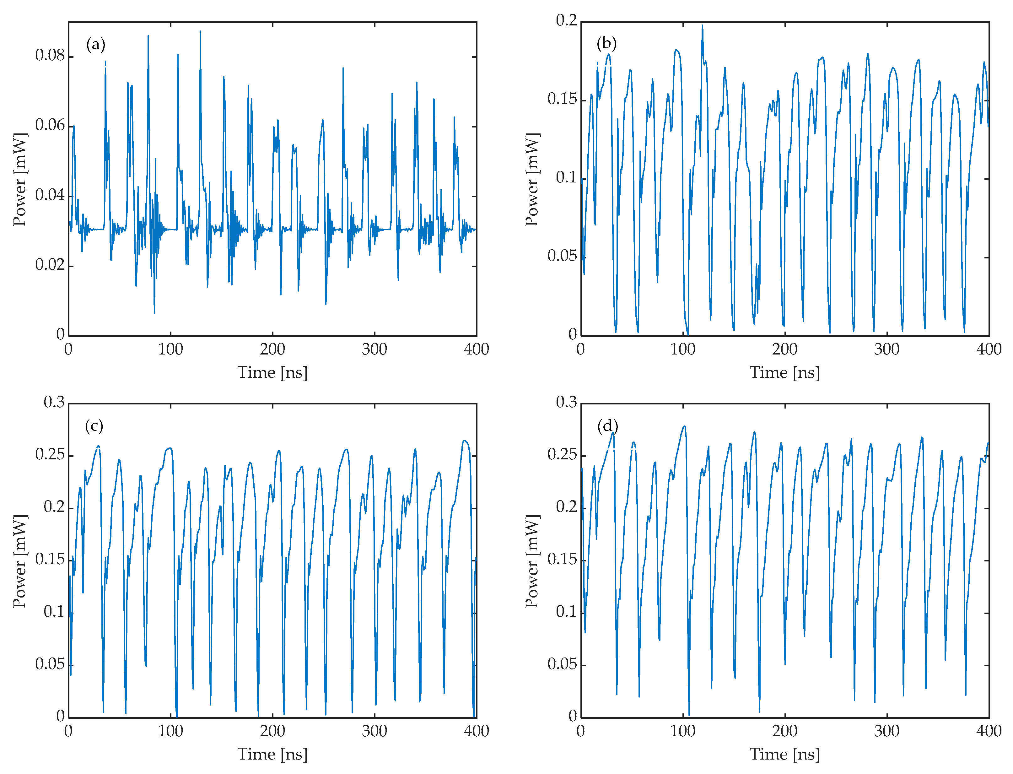
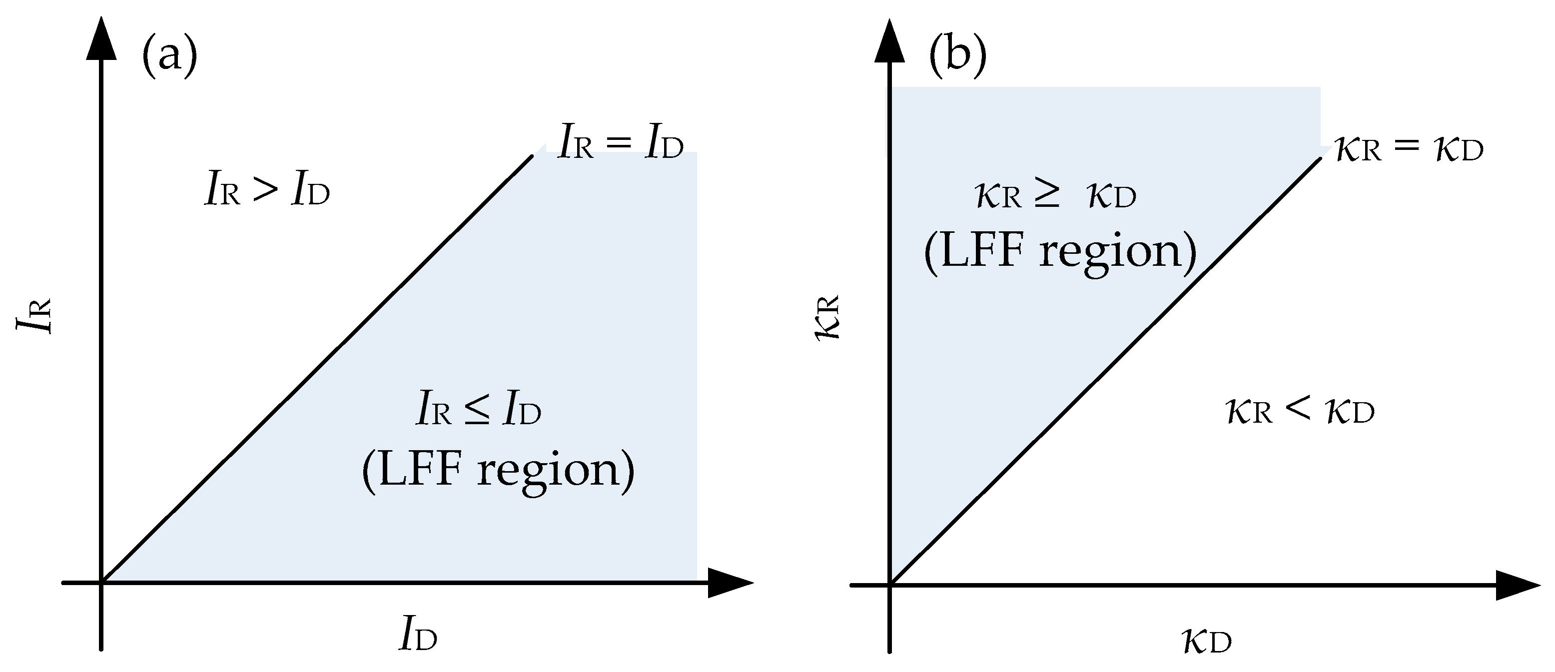
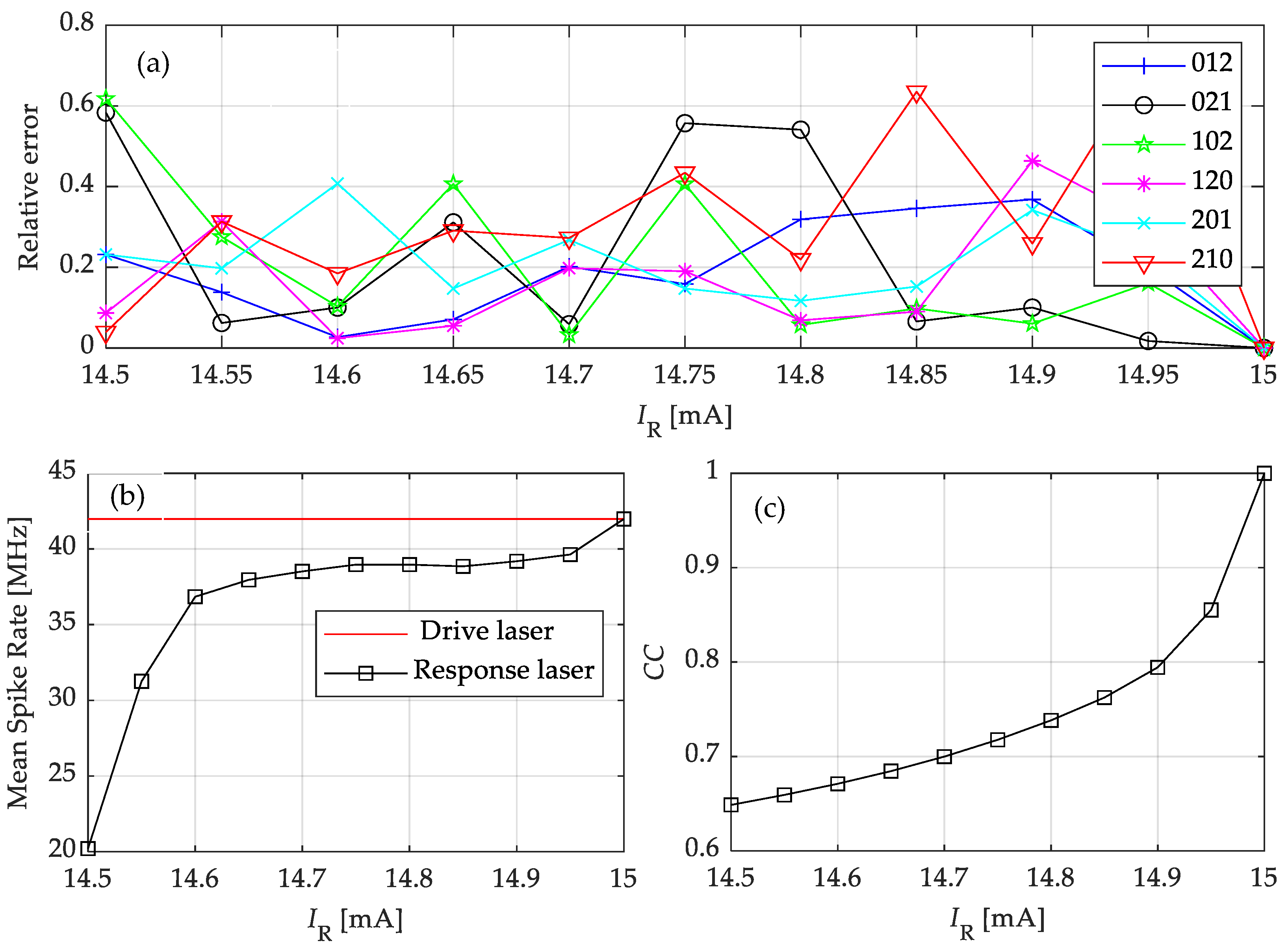
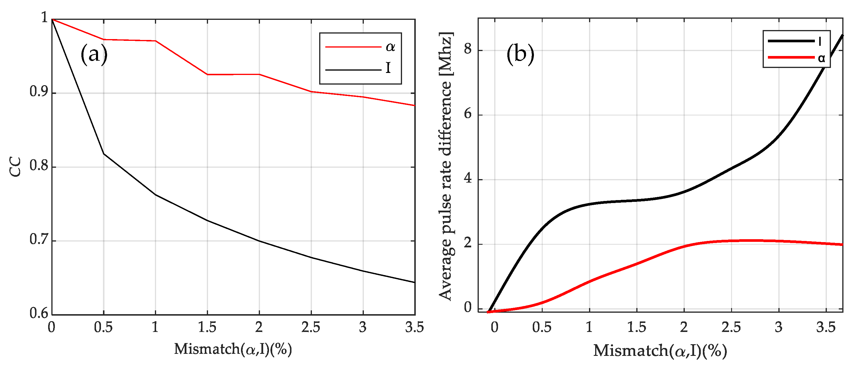
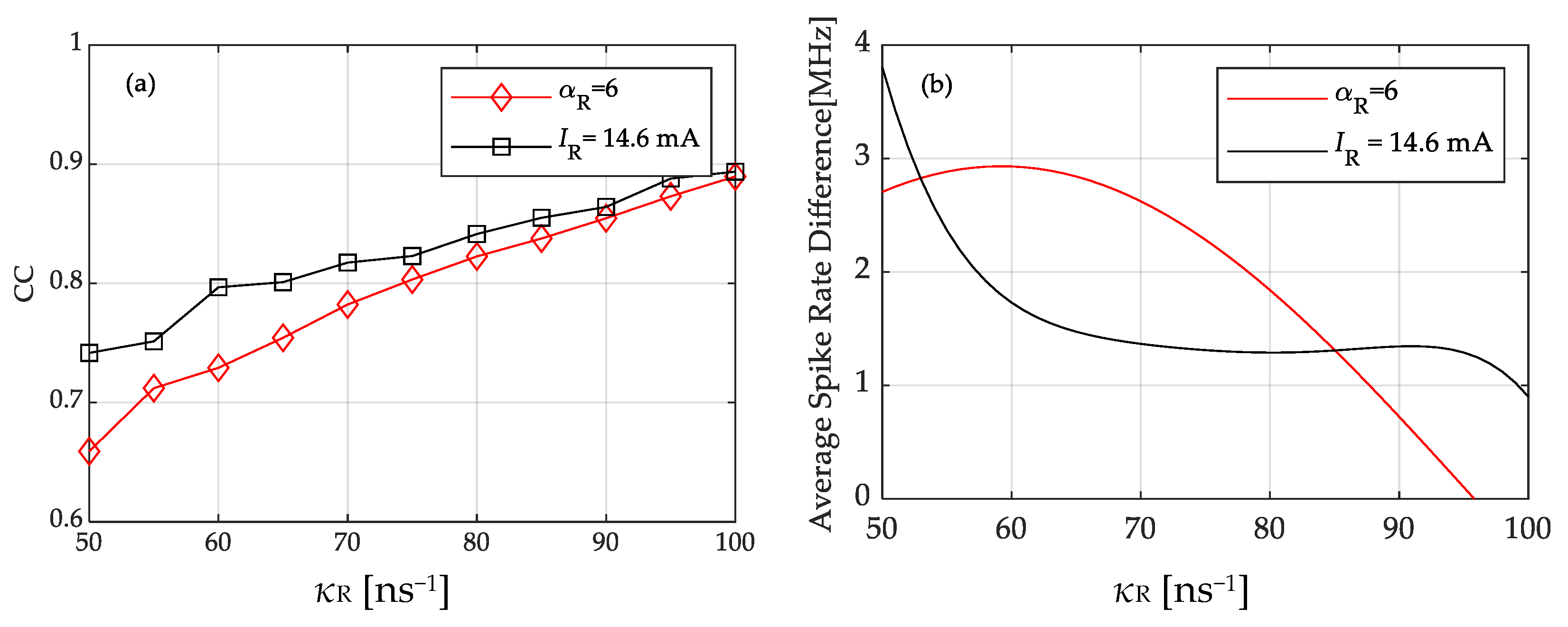
3.2. Influence of System Parameter Mismatch on the Transmission of LFF Waveforms

In practice, it is difficult to guarantee that both lasers have identical parameters. Thus, in this section, the effect of the mismatch of various physical parameters on the system performance is investigated.
The pump current is studied as the external operating parameter. Firstly, the error of the word probability between the drive and response laser is defined as follows,
d = | P R P D | P D ,
where d represents the event probability error, and PR and PD are the probability of a specific word of the response laser and drive laser, respectively.
From Figure 7a, certain transmission errors occur for all words when IR is smaller than ID. When IR is between 14.75 mA and 14.8 mA, the transmission of word 021 has the biggest error, and when IR is larger than 14.85 mA, the transmission of word 210 always has the largest error. When IR gradually increases to 15 mA, all of the errors converge to the zero point, indicating that the LFF waveform from the drive laser is successfully transmitted to the response laser. In addition, from Figure 7b, the red and black lines are rateD and rateR, respectively, and rateD is fixed at 41.97 MHz. The pulse rate of the response laser increases gradually with the injection current and increases rapidly when the IR is 14.5 mA and 14.6 mA, indicating that the rateR is greatly influenced by the injection current at this time. When IR increases from 14.7 mA to 15 mA, the curve increases smoothly to 41.97 MHz. What is more, Figure 7c shows the overall increase in the correlation coefficient CC with the increasing current.
The mismatch of the internal physical parameters, such as the linewidth enhancement factor α, can also induce a derivation on the LFF transmission. From Figure 8a, the transmission of the word 021 always has a large error when αR is not equal to 5. For instance, the error is larger than 0.7 when αR is 4.8 and 5.2, and reaches the largest value when αR is larger than 5.8. Meanwhile, the transmission of word 210 also always has a large error in the whole range of αR. In addition, the error of the transmission of word 012 is always small and less than 0.3. In Figure 8b, rateR increases rapidly and gradually approaches rateD when αR increases from 4.2 to 5, while in the range 5 to 6, rateR decreases steadily and gradually deviates from rateD. This means that when αR is smaller than αD, the LFF dynamic from the drive laser can hardly be mapped to the response laser. While for αR > αD, the LFF dynamic can be better transmitted. This can also be proven by the correlation coefficient. In Figure 8c, CC changes steeply when αR increases from 4.2 to 5, indicating that the LFF transmission is seriously affected in this region. When αR > αD, the system is more sluggish to parameter mismatch. These phenomena are consistent with the trend of the spike rate. Thus, αR < αD will cause a greater error in the transmission of the LFF waveform.
As the mismatch of linewidth enhancement factor and the pump current of the response laser can both induce an effect on the output LFF waveforms, to quantify which external operating parameter has a more significant effect on the transmission of the system, the mismatch is analyzed using the mismatch degree, which is defined in Equation (10),
M i s m a t c h ( γ ) = | γ R γ D | γ D ,
where γR and γD represent the external parameters of the response laser and the drive laser, respectively. As can be seen in Figure 9a, the red line is always higher than the black line, which means that the mismatch of the linewidth enhancement factor always has a limited impact on the system transmission, while the mismatch of the pump current IR can cause a more serious decrease in CC. This can also be proven by the difference in the average spike rate Diff, which is defined in Equation (11),
D i f f = | r a t e R r a t e D | ,
where rateR and rateD represent the average spike rate of the response and the drive laser, respectively. A larger Diff means a greater difference between the output of the drive laser and the response laser. From Figure 9b, the red line is always lower than the black line, which means that the mismatch in pump current IR can lead to a more severe increase in Diff. Therefore, the system transmission is more sensitive to the current mismatch, and to ensure the effectiveness of the transmission, efforts should be made to ensure that the pump current of the drive and response laser should be as consistent as possible.
From the above results, it can be found that parameter mismatch significantly influences the transmission quality. To discover methods that can guarantee LFF transmission, we investigated the influence of injection strength κR on CC when the parameters of two lasers are mismatched. In Figure 10, the red line denotes αD = 5 and αR = 6, while the rest of the parameters are the same. Similarly, the black line represents that ID = 15 mA and IR = 14.6 mA. From this figure, CC increases with κR for both mismatch conditions. The difference in the average spike rate also decreases when the injection strength is enhanced, as shown in Figure 10b. These results mean that increasing the strength can enhance the robustness of the LFF transmission, even though the parameters of the two lasers are different.

4. Discussion

In this paper, the transmission of the spike information, such as the spike rate and the probability of symbolic patterns embedded in the LFF dynamics in a cascaded laser system, are numerically demonstrated. In the last decades, there have been works studying the LFF synchronization in an open-loop configuration [28,29]. Most works utilize CC to measure the performance of LFF synchronization. However, when using the laser with optical feedback as a photonic neuron, CC is insufficient to describe the spike information because it can hardly reflect the timing of the spikes of LFF dynamics. Therefore, we analyzed the transmission of the LFF dynamic through both CC and the timing of spikes such as the spike rate and the probabilities of symbolic patterns. Firstly, the results show that the performance of the LFF transmission can be improved through increasing the injection strength, which is identical to the existing numerical and experimental results. Moreover, we find that to make the response laser generate the LFF dynamic, the injection strength should be larger than the feedback strength of the drive laser, and the pump current of the response laser should be smaller than that of the drive laser. Meanwhile, the mismatch of the pump current always has a more significant influence on the transmission of LFF waveforms than the internal physical parameters. For the transmission of the timing of spikes, we find that when there is a mismatch of the system parameters, the spike rate of the response laser is smaller than that of the drive laser. In addition, the symbolic pattern 210 always has a large transmission error when the parameters are mismatched. As the LFF waveform of the semiconductor laser is similar to what is produced by the neuron, and the results of this paper are beneficial for the practical application of photonic neurons and offer promising prospects for brain-like optical information transmission. Future work will focus on the LFF waveform of other laser systems, such as mutually coupled laser systems.

Author Contributions

X.D., S.Q. and W.W. contributed to the writing of the manuscript. All authors have read and agreed to the published version of the manuscript.

Funding

This work was supported in part by the National Natural Science Foundation of China (No. 62001077) and in part by the Dalian high-level talent innovation support plan (No. 2021RQ063).

Informed Consent Statement

Not applicable.

Data Availability Statement

Not applicable.

Conflicts of Interest

The authors declare no conflict of interest.

References

  1. Zhong, D.Z.; Deng, T.; Zheng, G.L. Manipulation of the complete chaos synchronization in dual-channel encryption system based on polarization-division-multiplexing. Acta Phys. Sin. 2014, 63, 070504. [Google Scholar] [CrossRef]
  2. Kanter, I.; Aviad, Y.; Reidler, I.; Cohen, E.; Rosenbluh, M. An optical ultrafast random bit generator. Nat. Photonics 2010, 4, 58–61. [Google Scholar] [CrossRef]
  3. Chen, C.Y.; Cheng, C.H.; Pan, D.K.; Lin, F.Y. Experimental generations and analyses of chaos-modulated pulses for pulsed chaos lidar applications based on gain-switched semiconductor lasers subject to optical feedback. Opt. Express 2018, 26, 20851–20860. [Google Scholar] [CrossRef] [PubMed]
  4. Rontani, D.; Choi, D.; Chang, C.Y.; Locquet, A.; Citrin, D.S. 6 Compressive sensing with optical chaos. Sci. Rep. 2016, 6, 35206. [Google Scholar] [CrossRef] [PubMed] [Green Version]
  5. Huang, Y.; Zhou, P.; Yang, Y.; Chen, T.; Li, N. Time-Delayed Reservoir Computing Based on a Two-Element Phased Laser Array for Image Identification. IEEE Photonics J. 2021, 13, 1–9. [Google Scholar] [CrossRef]
  6. Bao, X.; Zhao, Q.; Yin, H. A multiple-input multiple-output reservoir computing system subject to optoelectronic feedbacks and mutual coupling. Entropy 2020, 22, 231. [Google Scholar] [CrossRef] [Green Version]
  7. Tao, J.-Y.; Wu, Z.-M.; Yue, D.-Z.; Tan, X.-S.; Zeng, Q.-Q.; Xia, G.-Q. Performance enhancement of a delay-based Reservoir computing system by using gradient boosting technology. IEEE Access 2020, 8, 151990–151996. [Google Scholar] [CrossRef]
  8. Fischer, I.; van Tartwijk, G.H.M.; Levine, A.M.; Elsasser, W.; Gobel, E.; Lenstra, D. Fast Pulsing and Chaotic Itinerancy with a Drift in the Coherence Collapse of Semiconductor Lasers. Phys. Rev. Lett. 1996, 76, 220–223. [Google Scholar] [CrossRef] [Green Version]
  9. Shastri, B.J.; Nahmias, M.A.; Tait, A.N.; Robriguez, A.W.; Wu, B.; Prucnal, P.R. Spike Processing With a Graphene Excitable Laser. Sci. Rep. 2016, 6, 1–12. [Google Scholar] [CrossRef] [Green Version]
  10. Hurtado, A.; Schires, K.; Henning, I.; Adams, M. Investigation of vertical cavity surface emitting laser dynamics for neuromorphic photonic systems. Appl. Phys. Lett. 2012, 100, 103703. [Google Scholar] [CrossRef] [Green Version]
  11. Deng, T.; Robertson, J.; Hurtado, A. Controlled propagation of spiking dynamics in vertical-cavity surface-emitting lasers: Towards neuromorphic photonic networks. IEEE J. Sel. Top. Quantum Electron. 2017, 23, 1–8. [Google Scholar] [CrossRef] [Green Version]
  12. Xiang, S.Y.; Zhang, H.; Guo, X.X.; Li, J.F.; Wen, A.J.; Pan, W.; Hao, Y. Cascadable neuron-like spiking dynamics in coupled VCSELs subject to orthogonally polarized optical pulse injection. IEEE J. Sel. Top. Quantum Electron. 2017, 23, 1–7. [Google Scholar] [CrossRef]
  13. Tait, A.N.; Nahmias, M.A.; Shastri, B.J.; Prucnal, P.R. Broadcast and weight: An integrated network for scalable photonic spike processing. J. Lightwave Technol. 2014, 32, 3427–3439. [Google Scholar] [CrossRef]
  14. Ma, P.Y.; Shastri, B.J.; de Lima, T.F.; Huang, C.; Tait, A.N.; Nahmias, M.A.; Peng, H.T.; Prucnal, P.R. Simultaneous excitatory and inhibitory dynamics in an excitable laser. Opt. Lett. 2018, 43, 3802–3805. [Google Scholar] [CrossRef]
  15. Robertson, J.; Deng, T.; Javaloyes, J.; Hurtado, A. Controlled inhibition of spiking dynamics in VCSELs for neuromorphic photonics: Theory and experiments. Opt. Lett. 2017, 42, 1560–1563. [Google Scholar] [CrossRef] [Green Version]
  16. Selmi, F.; Braiv, R.; Beaudoin, G.; Sagnes, I.; Kuszelewicz, R.; Erneux, T.; Barbay, S. Spike latency and response properties of an excitable micropillar laser. Phys. Rev. E 2016, 94, 042219. [Google Scholar] [CrossRef] [Green Version]
  17. Hurtado, A.; Javaloyes, J. Controllable spiking patterns in long-wavelength vertical cavity surface emitting lasers for neuromorphic photonics systems. Appl. Phys. Lett. 2015, 107, 241103. [Google Scholar] [CrossRef] [Green Version]
  18. Nahmias, M.A.; Shastri, B.J.; Tait, A.N.; Prucnal, P.R. A leaky integrate-and-fire laser neuron for ultrafast cognitive computing. IEEE J. Sel. Top. Quantum Electron. 2013, 19, 1–12. [Google Scholar] [CrossRef]
  19. Peng, H.T.; Nahmias, M.A.; de Lima, T.F.; Tait, A.N.; Shastri, B.J.; Prucnal, P.R. Neuromorphic photonic integrated circuits. IEEE J. Sel. Top. Quantum Electron. 2018, 24, 6101715. [Google Scholar] [CrossRef]
  20. Tiana-Alsina, J.; Quintero-Quiroz, C.; Masoller, C. Comparing the dynamics of periodically forced lasers and neurons. N. J. Phys. 2019, 21, 103039. [Google Scholar] [CrossRef] [Green Version]
  21. Aragoneses, A.; Rubido, N.; Tiana-Alsina, J.; Torrent, M.; Masoller, C. Distinguishing signatures of determinism and stochasticity in spiking complex systems. Sci. Rep. 2013, 3, 1778. [Google Scholar] [CrossRef] [Green Version]
  22. Aragoneses, A.; Perrone, S.; Sorrentino, T.; Torrent, M.; Masoller, C. Unveiling the complex organization of recurrent patterns in spiking dynamical systems. Sci. Rep. 2014, 4, 4696. [Google Scholar] [CrossRef] [PubMed] [Green Version]
  23. Sorrentino, T.; Quintero-Quiroz, C.; Torrent, M.; Masoller, C. Analysis of the spike rate and spike correlations in modulated semiconductor lasers with optical feedback. IEEE J. Sel. Top. Quantum Electron. 2015, 21, 561–567. [Google Scholar] [CrossRef]
  24. Sorrentino, T.; Quintero-Quiroz, C.; Aragoneses, A.; Torrent, M.; Masoller, C. Effects of periodic forcing on the temporally correlated spikes of a semiconductor laser with feedback. Opt. Express 2015, 23, 5571–5581. [Google Scholar] [CrossRef] [Green Version]
  25. Tiana-Alsina, J.; Quintero-Quiroz, C.; Panozzo, M.; Torrent, M.; Masoller, C. Experimental study of modulation waveforms for entraining the spikes emitted by a semiconductor laser with optical feedback. Opt. Express 2018, 26, 9298–9309. [Google Scholar] [CrossRef]
  26. Prucnal, P.R.; Shastri, B.J.; de Lima, T.F.; Nahmias, M.A.; Tait, A.N. Recent progress in semiconductor excitable lasers for photonic spike processing. Adv. Opt. Photonics 2016, 8, 228–299. [Google Scholar] [CrossRef]
  27. Masoliver, M.; Masoller, C. Sub-threshold signal encoding in coupled FitzHugh-Nagumo neurons. Sci. Rep. 2018, 8, 8276. [Google Scholar] [CrossRef]
  28. Takiguchi, Y.; Fujino, H.; Ohtsubo, J. Experimental synchronization of chaotic oscillations in externally injected semiconductor lasers in a low-frequency fluctuation regime. Opt. Lett. 1999, 24, 1570–1572. [Google Scholar] [CrossRef] [PubMed]
  29. Locquet, A.; Masoller, C.; Mirasso, C.R. Synchronization regimes of optical-feedback-induced chaos in unidirectionally coupled semiconductor lasers. Phys. Rev. E 2002, 65, 056205. [Google Scholar] [CrossRef] [Green Version]
Figure 1. Schematic illustration of two cascaded photonic neurals.
Photonics 09 00483 g001
Figure 2. Output of the drive laser with optical feedback under different system parameters. (a) κD = 10 ns−1 and ID = 15 mA, (b) κD = 50 ns−1 and ID = 15 mA, (c) κD = 10 ns−1 and ID = 22 mA, and (d) κD = 50 ns−1 and ID = 22 mA.
Photonics 09 00483 g002aPhotonics 09 00483 g002b
Figure 3. Word probability (a) and pulse rate (b) of the drive laser at different feedback strengths.
Photonics 09 00483 g003
Figure 4. Output of response laser under different pump currents. κD = κR = 50 ns−1. Left column: ID = 15 mA. Middle column: ID = 16 mA. Right column: ID = 17 mA. (ac): IR < ID. (df): IR = ID. (gi): IR > ID.
Photonics 09 00483 g004
Figure 5. Output of response laser under different injection strengths. ID = IR = 15 mA, κD = 50 ns−1. (a) κR = 10 ns−1, (b) κR = 40 ns−1, (c) κR = 50 ns−1, and (d) κR = 100 ns−1.
Photonics 09 00483 g005
Figure 6. Parameter relationships that can make the response laser generate the LFF dynamic. (a) The relationship of IR and ID and (b) the relationship between κR and κD.
Photonics 09 00483 g006
Figure 7. Effect of pump current mismatch on system transmission. (a) Event probability error, (b) pulse rate, and (c) correlation coefficient.
Photonics 09 00483 g007
Figure 8. Effect of linewidth enhancement factor mismatch on system transmission. (a) Event probability error, (b) pulse rate, and (c) correlation coefficient.
Photonics 09 00483 g008
Figure 9. Effect of external parameter mismatch on (a) the correlation coefficient and (b) the difference of the average spike rate.
Photonics 09 00483 g009
Figure 10. Effect of injection strength on the LFF transmission performance. The pump current and linewidth enhancement factor are 15 mA and 5, respectively. (a) Correlation coefficient, (b) average spike rate difference.
Photonics 09 00483 g010
Table 1. Parameters and values.
SymbolParameterValue
GGain coefficient1.5 × 104 m3/s
τnCarrier lifetime2 × 10−9 s
τpPhoton lifetime2 × 10−12 s
N0Carrier density at transparency1.5 × 108 m−3
εGain saturation coefficient0.05
τFeedback delay time1 × 10−9 s
VActive region volume1.5 × 10−16 m3
Table 2. Ordinal patterns for D = 3.
Serial NumberWordRelationQuantity
1012 Δ t ( i ) < Δ t ( i + 1 ) < Δ t ( i + 2 ) n1
2021 Δ t ( i ) < Δ t ( i + 2 ) < Δ t ( i + 1 ) n2
3102 Δ t ( i + 1 ) < Δ t ( i ) < Δ t ( i + 2 ) n3
4120 Δ t ( i + 1 ) < Δ t ( i + 2 ) < Δ t ( i ) n4
5201 Δ t ( i + 2 ) < Δ t ( i ) < Δ t ( i + 1 ) n5
6210 Δ t ( i + 2 ) < Δ t ( i + 1 ) < Δ t ( i ) n6
Publisher’s Note: MDPI stays neutral with regard to jurisdictional claims in published maps and institutional affiliations.

