Article

Beam Smoothing Based on Prism Pair for Multistep Pulse Compressor in PW Lasers

1
State Key Laboratory of High Field Laser Physics and CAS Center for Excellence in Ultra-Intense Laser Science, Shanghai Institute of Optics and Fine Mechanics, Chinese Academy of Sciences, Shanghai 201800, China
2
Center of Materials Science and Optoelectronics Engineering, University of Chinese Academy of Sciences, Beijing 100049, China
*
Author to whom correspondence should be addressed.
Photonics 2022, 9(7), 445; https://doi.org/10.3390/photonics9070445
Submission received: 4 June 2022 / Revised: 19 June 2022 / Accepted: 21 June 2022 / Published: 23 June 2022

Abstract

:
Ultra-short, ultra-intense lasers provide unprecedented experimental tools and extreme physical conditions, enabling the exploration of the frontiers of basic physics. Recently, a multistep pulse compressor (MPC) method was proposed to overcome the limitations of the size and the damage threshold of gratings in the compressor for the realization of a higher-peak-power laser. In the MPC method, beam smoothing is an important process in the pre-compressor. In this study, beam smoothing based on prism pairs is investigated, and the spatial profiles, as well as spectral dispersion properties, are analyzed. The simulation results demonstrate that the prism pair can effectively smooth the laser beam. Furthermore, beam smoothing is found to be more efficient with a shorter separation distance if two prism pairs are arranged to induce spatial dispersion in one or two directions. The beam smoothing results obtained in this study will help optimize optical designs in petawatt (PW) laser systems, thereby improving their output and operational safety.

1. Introduction

Ultra-intense femtosecond laser pulses can generate extremely physical conditions for the exploration of the frontiers of basic physics and help reveal new phenomena of matter. Consequently, it has attracted widespread attention in recent years [1,2,3,4]. Since the chirped pulse amplification (CPA) method was proposed in 1985 [5], more than 50 lasers worldwide have achieved peak powers of several hundred terawatts (TWs) and even petawatts (PWs) [6,7,8]. Several hundred PW femtosecond (PW-fs) laser systems are being developed or built in Europe (ELI-200PW [9]), Russia (XCLES-200PW [10]), the USA (OPAL-75PW [11]), and China (SEL-100PW [12]). In a femtosecond PW (fs-PW) laser system, the laser pulse is first stretched from femtosecond to nanosecond and subsequently amplified using CPA or optical parametric chirped pulse amplification (OPCPA) [13] techniques, wherein the chirped nanosecond pulse is compressed to an ultrashort femtosecond pulse using a grating-based pulse compressor in the final stage.
In an fs-PW laser system, the compression system is usually a Treacy four-grating compressor [14], wherein the first grating surface bears the largest input pulse energy, and the fourth grating surface bears the shortest pulse duration or the highest peak power. Thus, the damage thresholds of the first and fourth gratings limit the maximum input and output pulse energy, respectively. The output laser beam of the main amplifier typically has a large laser spatial intensity modulation (LSIM) owing to the pump laser, and hotspots appear in the beam due to wavefront distortion at high spatial frequency, resulting from the diffuse reflection of dust or defects in optical components. These strong LSIM or hot spots reach the damage threshold of the grating ahead of the average intensity and limits the output pulse energy at the end of the laser system.
Recently, a novel optical design called a multistep pulse compressor (MPC) was proposed to increase the input/output pulse energy of grating-based pulse compressors [15]. With the MPC method, beam smoothing based on prism pairs is an important process that is used as the pre-compressor step. However, the beam-smoothing process has not yet been thoroughly investigated. Because the prism pair introduces spectral dispersion to the laser pulse with a relative broadband spectrum, this study analyzes the spatial properties in conjunction with the spectral dispersion. The simulation results demonstrated that beam smoothing based on prism pairs can be used to reduce the laser spatial intensity modulation ratio (LSIMR) of the laser beam on the surfaces of the first and last gratings in the compressor. Thus, the pulse energies of the incident and output laser beams can be increased without damaging the grating. Additionally, this beam-smoothing-based prism pair can be applied before the main amplifier to smooth the incident laser beam before the large crystal for high-energy amplification to protect the expensive crystal.

2. Principle of Prism-Pair-Induced Spatial and Spectral Dispersions

A prism pair is a set of commonly used optical dispersion elements that has the advantages of simple composition, flexible operation, low loss, and precisely adjustable spectral dispersion. Negative spectral dispersion is typically induced by prism pairs to compensate for the positive dispersion and achieve ultrashort laser pulses for small laser beams in oscillators. Contrary to the induced useful negative spectral dispersion, the induced spatial dispersion is harmful in many applications. Then, the laser beam passes through the prism pair twice—forward and backward—to automatically compensate for the prism-pair-induced spatial dispersion.
Recently, it was found that the induced spatial dispersion is also useful in laser microscopy and laser micromachining applications [16,17]. In these applications, the laser beam is intentionally introduced to an amount of spatial dispersion using a grating/prism pair and then focused using a lens or other optical equipment. The purpose of this special optical design is to achieve the highest focal intensity at the focal point only, so as to ensure that the laser intensity near the focal point decreases rapidly. Thus, the optical section capability will be improved near the focal point, resulting in increased resolution and contrast in microscopy or micromachining applications. This method was named spatiotemporal focusing [18,19].
Recently, it was reported that this spatiotemporal focusing can be used in ultrahigh-peak-power laser systems with large beam sizes [20,21,22,23]. In this MPC optical design, the intentionally induced spatial dispersion using a grating or prism pair was used to smoothen the laser beam with large beam sizes to reduce its LSIMR [15].
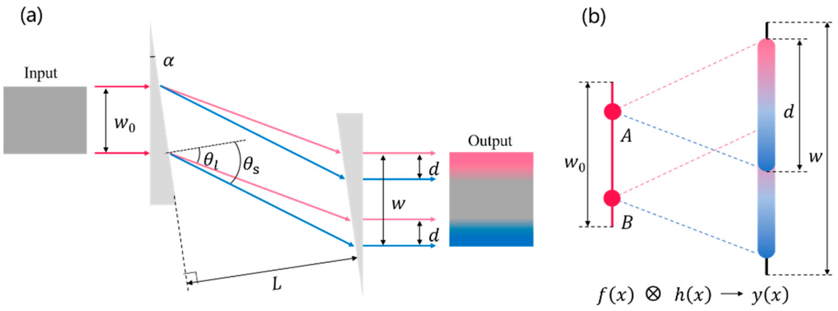
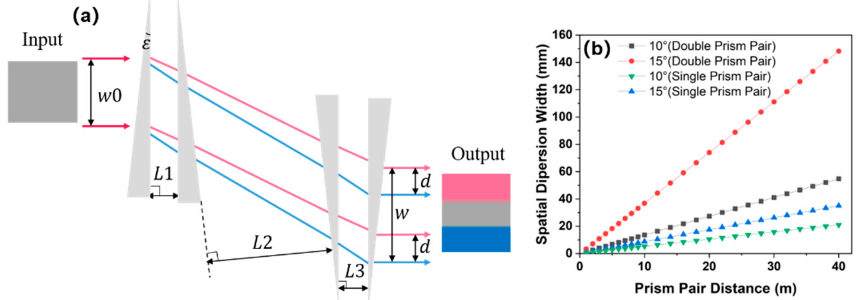
In the spatial domain, the passing of a laser beam through a prism introduces angular dispersion, which extends the laser beam in the angular dispersion direction owing to the broad spectrum, and another prism with the same optical parameters is located parallel to the first one to collimate the output laser beam. The optical setup of the prism pair with two right-angle prisms for laser beam smoothing is shown in Figure 1a, where L is the perpendicular distance between the two prisms, α is the apex angle of the two prisms, θ s and θ l are the exit angles of the shortest and longest wavelengths, respectively, d is the induced spatial dispersion width, w 0 and w are the input and output laser beam widths along the X-axis, respectively. The induced spatial dispersion width d can be expressed as d = L tan θ s tan θ l cos   α . Considering the relationship between the exit angle of the beam θ and the apex angle of the prism, as well as that between θ and the refractive index of the prism pair at different wavelengths, the induced spatial dispersion width d can also be expressed as follows:
d = L ( M S 1 M s 2 M l 1 M l 2 ) cos α
M s = n s sin ( α arcsin sin δ n s )
M l = n l sin ( α arcsin sin δ n l )
where δ is the incident angle of the laser beam, and n s and n l are the refractive indices of the prism pair at the shortest and longest wavelengths, respectively. M s and M l are the dependent variables related to the incident angle and wavelength. According to the above formulas, the induced spatial dispersion width d is only related to the perpendicular distance between the two prisms L and the prism apex angle α when the wavelength range and the incident angle are constant.
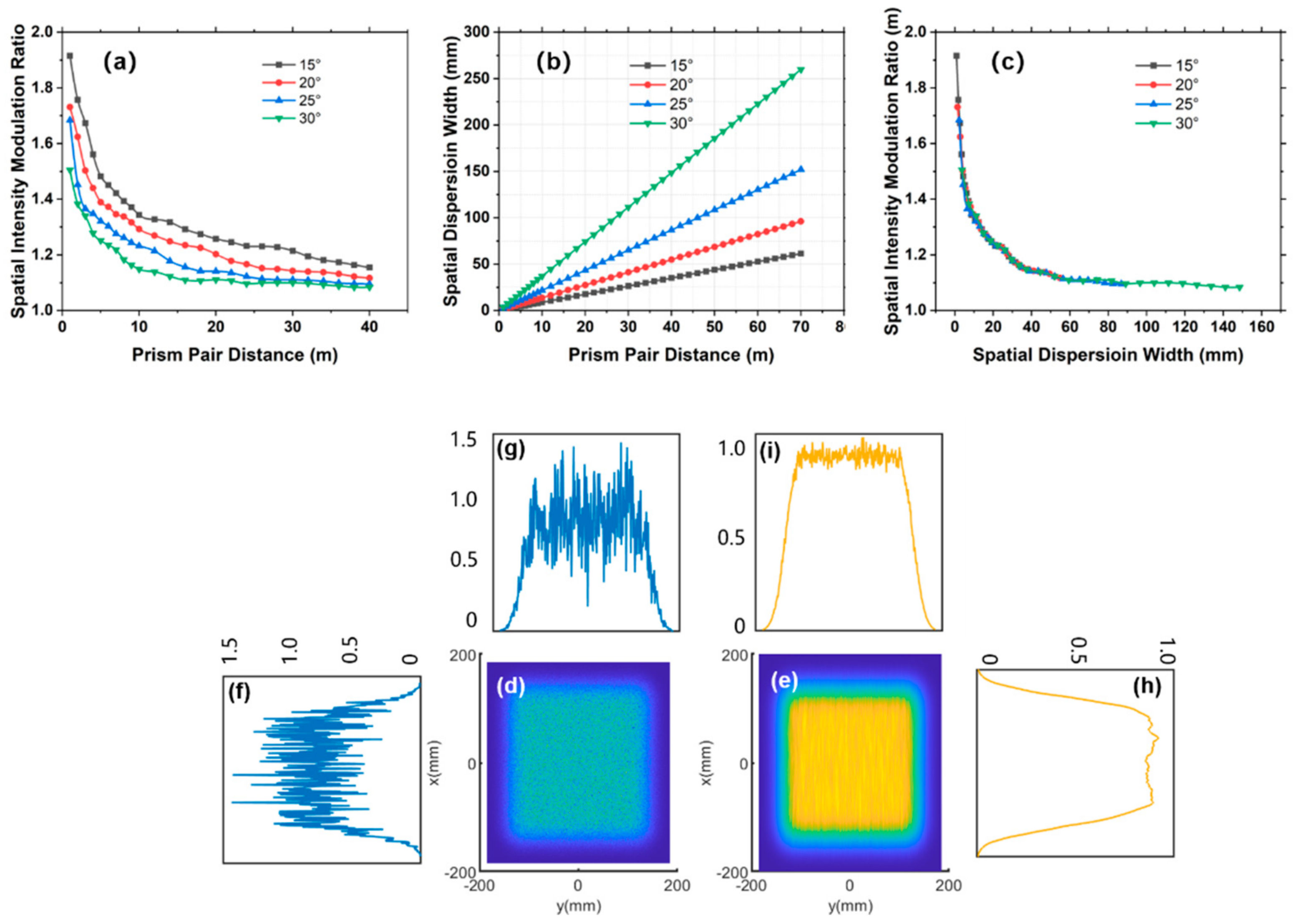
From these equations, it is clear that d is linearly related to the distance L between the two prisms, and also related to both the apex angle of the prism α and the exit angles of the beam θ . The refractive index of the prism pair is constant at the same wavelength; thus, the changing of the spectral range significantly affects d . When the induced spatial dispersion width d is smaller than the laser beam size, the center part of the output laser beam has a full bandwidth spectrum and no spatial dispersion, whereas the laser beam on both sides exhibits spatial dispersion.
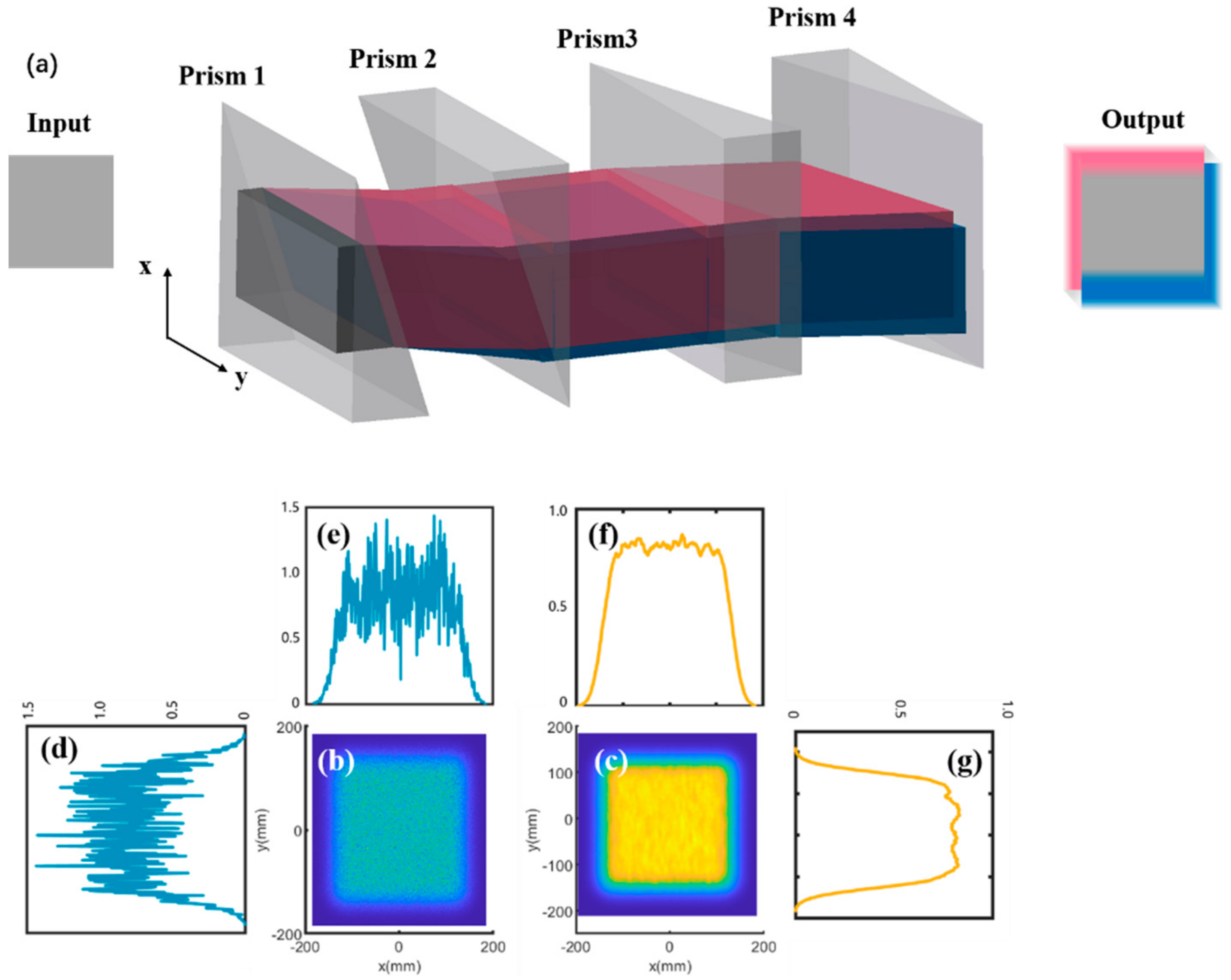
Owing to the angular dispersion of the prism pair, light with different wavelengths will be output at different angles from the first prism and will be distributed at different positions after being collimated by the second prism. The spatiospectral distribution of the nearby spots of the incident laser beam will overlap in the output beam; therefore, the intensity of the output laser beam is redistributed. Figure 1b illustrates this redistribution principle using two nearby input light spots, A and B. Assuming that the laser spectra are the same for all spots in the incident laser beam, both A and B will be extended from a spot to a line with a length d . If the distance between A and B is smaller than d , there is spatial overlapping of different wavelengths in the output laser beam for A and B. The process depicted in Figure 1b, which induces spatial dispersion by angular dispersion, can also be explained using convolution, as expressed in the following equation:
y x = + f n h x n = f x h x
where f x is the incident laser intensity distribution function along the X-axis, the function h x is the spectral intensity profile projected on the X-axis, and h y is the obtained output smoothed beam profile on the X-axis. It is known that a convolution operator can smooth figures or signals. The final laser beam intensity is obtained by accumulating the intensity of light that arrived at the same spatial position through the prism pair. Consequently, the output laser beam is smoothed owing to convolution and intensity redistribution.
Hotspots are the typical damage risk for high-peak-power lasers owing to their small beam size and local high intensity. Therefore, we assume that points A and B have a diameter of 2 × r ; as a result, the peak power of the two hot spots is decreased by approximately 2 × r × d / π × r 2 = 2 / π × d / r times. After summing all the corresponding spatio-spectral intensity values at every point on the extended output beam line, the beam smoothing effect of the output laser beam is found to be related to the d / r ratio. This indicates that both increasing d and reducing r have a significant effect on smoothing the output laser beam. Specifically, inducing a larger spatial dispersion width d onto hotspots with a high spatial frequency 1 / r is easier to smooth.
In a PW laser, the laser pulse is usually chirped to the order of nanoseconds to avoid laser-induced damage to the amplification crystal. Compared with the large spectral dispersion of the input laser beam induced by the stretcher, the induced spectral dispersion was negligible. For tens of femtosecond transform-limited laser pulses with a broadband spectrum, the induced small spectral dispersion is important to achieve good compression of the laser pulse. Based on previous works, the spectral dispersion induced by a single pass of a prism pair can be expressed as follows [24]:
G D D = λ 3 2 π c 2 d 2 p d λ 2 ,
T O D = λ 4 4 π 2 c 3 3 d 2 p d λ 2 + λ d 3 p d λ 3
where G D D and T O D are the second-order and the third-order dispersions, respectively; d 2 p d λ 2 and d 3 p d λ 3 are the second-order and the third-order derivatives of the optical path with respect to wavelength, respectively; λ is the wavelength; c is the speed of light. Furthermore, it was found that the combination of a prism pair and a grating pair can help to compensate for the third-order dispersion and help to achieve a shorter compressed pulse duration because the prism pair and the grating pair have the same signs for G D D and opposite signs for T O D [14,24]. Note that the material dispersion of the prism pair discussed here is relatively larger because of the large beam size induced by the large and thick prism; therefore, the spectral dispersion will be seriously affected by the material dispersion compared with the prism pair used for a small beam size, which is discussed in the following section.

3. Simulation Results in Spatial Domain

In the specific simulation, the spatial profile of the incident beam is set as a 10th-order flat top super-Gaussian beam with a beam size of 370 × 370 mm2, and the LSIMR of the incident laser beam is set to be 2.0. The spectral shape of the input beam is set to be a 7th-order flat-top super-Gaussian; the spectral range is 825–1025 nm. The incident beam is sampled at an interval width of 1 mm.
Using the ray-tracing method, the spatial distribution of different wavelengths in the sampling point with a full spectrum is calculated individually. Finally, an output laser beam with a new spatial distribution is obtained. The smoothing effect of the output laser beam is discussed in detail by changing the parameters of the prisms and various combinations of prism pairs.

3.1. One Prism Pair

In this study, the beam-smoothing effect of right-angle prisms with apex angles of 15°, 20°, 25°, and 30° is simulated, and the value of LSIMR is used to characterize the effect of beam smoothing. When the laser beam is incident at 0° on the right-angle prism pairs but at different apex angles, the variations of LSIMR and the variation in the induced spatial-dispersion-width as the distance of the prism pair changes are shown in Figure 2a and Figure 2b, respectively.
In Figure 2a, LSIMR decreases rapidly from 2.0 to about 1.3, indicating that the prism pair can effectively smooth the beam by inducing spatial dispersion. However, LISMR drops from 1.3 to around 1.1 require a relatively long distance between the right-angle prism pair. By comparing the curves of LISMR for different prism apex angles, it is concluded that achieving the same LISMR requires that the prism pair distance for the apex angle of 30° is much shorter than that for 15°. In Figure 2b, the induced spatial dispersion width d increases linearly with the perpendicular distance of the prism pair L . Because the exit angle of the light passing through the prism pair is related to the apex angle of the prism, the same induced d requires that the distance of the prism pair L for an apex angle of 30° be much shorter than 15°. For prisms with different apex angles, the curves of LISMR show the same downward trend, and the trend changes are almost the same, indicating that LISMR are closely related to the induced d . The results are shown in Figure 2c, which further confirms that the prism pair can effectively smooth the laser beam.
By comprehensively comparing the induced spatial dispersion width and LISMR for prism pairs with different apex angles, as long as the induced spatial dispersion width d reaches approximately 60 mm, LISMR is reduced to approximately 1.1, and the laser beam is well smoothed. Figure 2d–i show the one-dimensional (1D) and two-dimensional (2D) spatial intensity profiles of the input laser beam and those of the smoothed output laser beam. The input laser beam is well smoothed on the X- and Y-axes, and the LISMR is approximately 1.1.
This discussion pertains to an ideal case with a smooth spectrum without spectral intensity modulation. However, a completely smooth laser spectrum does not exist in reality. Here, we simulate laser beam smoothing using modulated spectra. Figure 3a shows the 1D shape of the ideal and modulated spectra. As the distance of the prism pair is increased, the LSIMR curves that a laser beam passed through a right-angle prism pair with an apex angle of 20° are shown in Figure 3b. According to the simulation results, the spectrum with intensity modulation does not have a significant influence on the LSIMR. This is because the LSIMR is the convolution of the intensity of the incident laser beam and the intensity of the spectrum of the laser beam. Figure 3c–h shows the 1D and 2D spatial intensity profiles of the output laser beam smoothed by the input laser beam with an ideal spectrum and modulated spectrum passing over a distance of 8 m prism pair with an apex angle of 20°. From Figure 3c–h, it can be seen more intuitively that the shape of the spectrum has no effect on the smoothing beam.
From the above analysis, the larger the induced spatial dispersion width, the greater is the decrease in the LSIMR. A larger apex angle of the right-angle prism can help to achieve a larger induced spatial dispersion width. Nevertheless, the right-angle prism pair with a large apex angle may have total reflection when it is incident at 0°, and dispersion is induced into the right-angle prism pair only on the oblique side. Next, we determine whether replacing the right-angle prism pair with an isosceles prism pair introduces a larger amount of dispersion. The optical setup and simulation results are shown in Figure 4a and Figure 4b, respectively, where β is the apex angle of the isosceles prism. Compared with the simulation results of the right-angle prism pair, the induced spatial dispersion width of the isosceles prism pair with parallel incidence can be achieved using a longer prism-pair distance, and isosceles prisms with parallel incidence do not have a better smoothing beam effect than right-angle prisms. According to formulas (1)–(3), the induced spatial dispersion width d is significantly related to the apex angle and incident angle of the prism. The larger the apex angle and zero incident angle, the better the beam smoothing effect. A full-spectrum hotspot parallel enters the isosceles prism, and the induced dispersion width is smaller than the induced dispersion width of right-angle prisms with zero incident angle when the apex angle β = α . As a result, the shape of the prism pair has no effect on the spatial dispersion.

3.2. Two Prism Pairs in Same Direction

From the simulation results of the laser beam smoothing by a single prism pair, the LSIMR decreases to approximately 1.1, which requires an induced spatial dispersion width of approximately 60 mm. This means that a long distance between the prism pairs is required to achieve these conditions. However, in reality, a long distance between prism pairs limits the application of experiments. Here, there is an effective prism pair, where the visual single prism is combined with two prisms to achieve a relatively larger apex angle. Thus, it is possible to increase the induced dispersion width with a relatively small experimental space. The optical setup is shown in Figure 5a, where the four prisms are exactly the same, and ε is the apex angle. L 1 , L 2 , and L 3 are the distances between the prisms, and L = L 1 + L 2 + L 3 . Usually, L 1 0 ,   L 3 0 and L = L 1 + L 2 + L 3 L 2 , which indicates the total distance between the first and fourth prisms. In this study, L 1 and L 2 are both set to 0.05 m, and the total distance L is changed by varying L 2 . There are many combinations of prisms and various values of L 1 , L 2 , L 3 . L 1 and L 2 are not necessarily equal; this is the result of the following display: In a real experiment, the right-angle surface of the first prism is parallel to the right-angle surface of the second prism, and the first prism is close to the second prism. The distance between the first and second prisms could be adjusted. Similarly, the third and second prisms are placed in the same way as above. To maintain the consistency of the propagation direction of the input laser beam and output laser beam, the exit surface of the second prism and the entrance surface of the third prism must be kept parallel. From the simulations of various combinations of prisms, L 2 contributes the most to the spatial dispersion width d , and the contributions of L 1 and L 2 are the same. At this time, a single hotspot is extended into a line with a length of d = d x 1 + d x 2 + d x 3 d x 2 and a width of 2 × r , and the local intensity is decreased by approximately 2 d x 1 + d x 2 + d x 3 / π r 2 d x 2 / π r , where d x 1 , d x 2 , and d x 2 are the induced spatial dispersion widths along the X-axis by the prism distances of L 1 , L 2 , and L 3 , respectively.
The simulation results showing the variation of the spatial dispersion width d with L are shown in Figure 5b, where the apex angles of the prisms are 10° and 15°. It is found that the spatial dispersion width of two prism pairs is equivalent to that of a single prism pair with twice the apex angle. This means that two prism pairs with an apex angle of 15° are equivalent to a single prism pair with an angle of 30°. For a small apex angle prism of 15°, when the spatial dispersion width reaches 60 mm or 10 mm, a single prism pair needs a distance of 68 m or 12 m, respectively, whereas two prism pairs only need a distance of 16 m or 3 m. The results save 52 m or 9 m of prism pair distance, respectively, by comparing a single prism pair of 15° with an induced spatial dispersion width of 60 mm or 10 mm. Obviously, this combination of prisms not only reduces the spacing between prisms but also retains the advantages of prisms with small apex angles.

3.3. Two Prism Pairs in the Perpendicular Directions

In the above simulation results, the two prism pairs can effectively smooth the beam by inducing spatial dispersion along the X-axis. To introduce angular dispersion in two axes and save experimental space, the other prism pair is placed perpendicular to the first prism pair, which can induce spatial dispersion along the Y-axis direction. The optical setup is shown in Figure 6a. It should be noted that the single hotspot is extended not into a line but into an area of d x × d y after passing through two prism pairs, where d x is the induced spatial dispersion width along the X-axis, and d y is the induced spatial dispersion width along the Y-axis. Consequently, the overall induced spatial dispersion area is approximately d x × d y . For a single hotspot with a diameter of 2 × r , the local intensity decreases by approximately d x × d y / π r 2 . This ratio is only calculated for a single hotspot; the overall effect is the superposition of convolution integrals, and the lowest value is reduced to the average value, which is not infinitely reduced.
To maintain the small apex angle of the prism pair, a right-angle prism pair with an apex angle of 15° is chosen in the simulation, inducing angular dispersion in both the X and Y directions. This indicates that the spatial dispersion width reaches 60 mm, and the laser smoothing effect is significant. Because the introduced spatial dispersion width is divided into two parts in the X and Y directions, and the total spatial dispersion width d = d x × d y is constant, using the inequality a b a + b / 2 , it can be concluded that when d x = d y , the d x + d y is the minimum, where a and b are real positive numbers. Thus, the distance between the first prism pair with an apex angle of 15° is set to 9 m to introduce a spatial dispersion width of approximately 8 mm along the X-axis. The perpendicular distance between the second prism pair is also 9 m. As a result, a total prism pair distance of approximately 18 m can smooth the laser beam to an LSIMR of 1.1, which significantly reduces the total optical space. Figure 6b–g shows the 1D and 2D spatial profiles of the input laser beam and those of the smoothed output laser beam in both the X- and Y-axes, where the induced spatial dispersion width is 10 mm along the X-axis and 6 mm along the Y-axis.

4. Simulation Results in Spectral Dispersion

The laser beam passing through the prism pair not only changes the spatial characteristics of the laser beam but also affects its temporal properties. The spectral dispersion induced by the prism pair of the output laser beam consists of the following two parts: the material dispersion of the prism pair and the negative dispersion caused by the angular dispersion of the prism pair. For the PW laser facility, the laser beam is relatively large, and the prism pair used for beam smoothing also has a large optical size, which implies a relatively thick optical path in the prisms. As a result, the positive dispersion induced by the prism pair material is considerable, which is different from the prism pair with a small size. The positive dispersion caused by the material is expressed as follows:
φ ω = ω c n ω l
G D D m = d 2 φ d ω 2 = λ 3 l 2 π c 2 d 2 n d λ 2
T O D m = d 3 φ d ω 3 = λ 4 l 4 π 2 c 3 3 d 2 n d λ 2 + λ d 3 n d λ 3
where G D D m and T O D m are the positive dispersions of the second-order and third-order, respectively. d 2 n d λ 2 and d 3 n d λ 3 are respectively the second-order and the third-order derivatives of the refractive index to wavelength. l is the distance traveled in the prism pair.
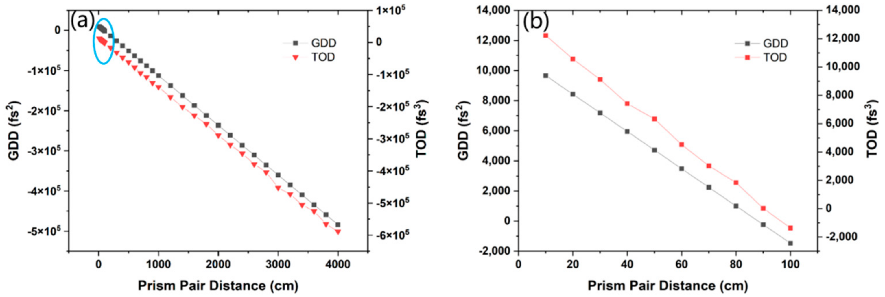
For the negative dispersion from the angular dispersion induced by the prism pair, the second-order dispersion GDD and the third-order dispersion TOD are simulated based on formulas (5) and (6), respectively. In the simulation, the apex angle of the prism is 20°, the center wavelength is 925 nm, and the beam size is 370 × 370 mm2. The spectral shape of the input beam is set to a 7th-order flat-top super-Gaussian, and the spectral range is 825–1025 nm. The GDD and TOD generated by material dispersion are related to the prism insertion; the first prism insertion is 10 mm, and the second prism insertion is 400 mm in this simulation here. For a single prism pair, the induced GDD and TOD with a center wavelength of 925 nm vary with the prism pair distance. Figure 7b shows the enlarged part marked by the blue box in Figure 7a. As can be seen, the total introduced GDD and TOD are both positive values at the beginning because the relatively large prism and thick material induce positive dispersion. When the prism pair is spaced by approximately 0.9 m, the angular dispersion induces negative dispersion, and the material-induced positive dispersion is balanced, which induces a nearly zero GDD and TOD. In this case, the induced spatial dispersion width d is approximately 1.3 mm. As the prism pair distance increases, GDD and TOD become negative and increase linearly.
In fact, the loss of the prism pair is low, and thus its absorption can be ignored. The positive and negative values of the second-order and third-order dispersions can be precisely adjusted by adjusting the prism insertion. In other words, the total dispersion of a fixed small-distance prism pair can be adjusted positively and negatively by changing the material dispersion, which can be changed by varying the passing through the length of the prism pair based on formulas (7)–(9). According to the simulation results, the second-order and third-order dispersions induced by prism pairs change continuously from positive to negative with increasing distance between prism pairs. When the prism pair distance reaches the meter-level unit, the second-order and third-order dispersions are both negative. At this time, the positive dispersion introduced by the stretcher and the material dispersion of the front components are pre-compensated. Meanwhile, we can fully compensate for the negative chirp with a thick glass plate [25] so that the laser beam can be shaped spatially without changing the temporal characteristics. Note that grating pairs together with prism pairs are always used to fully compensate for the third-order dispersion of the whole laser system to achieve a short pulse duration with broad spectral bandwidth because the third-order dispersions induced by prism pairs and grating pairs are opposite [26]. Then, the prism pair added before the grating-based compressor helps compensate for the third-order and even the fourth-order spectral dispersion in the PW laser [26,27].

5. Discussion and Conclusions

This study proposed a beam smoothing method based on prism pairs to reduce the hotspot intensity in high-peak-power laser beams due to the diffuse reflection of dust or defects in optical elements. The proposed method can prevent damage to the first and fourth gratings in the grating-based compression system. Furthermore, the factors influencing the smoothing beam based on the prism pair are explored. The simulation results demonstrate that LSIMR is closely related to the induced spatial dispersion width. The spatial dispersion width is found to be strongly correlated with the apex angle of the prism pair, the distance between the prism pair, and incident beam characteristics.
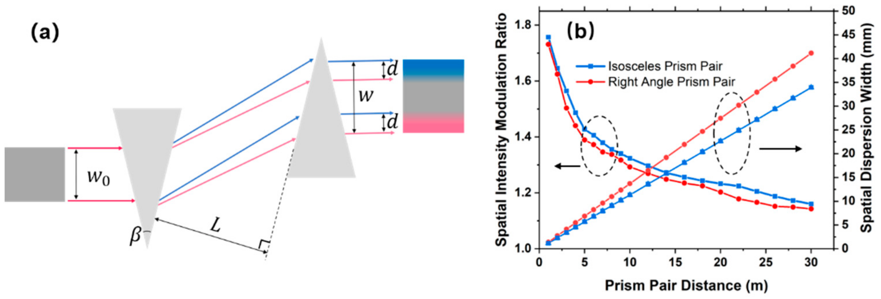
The laser beam smoothing effect of single as well as dual prism pairs are simulated. The two prism pairs proposed to introduce spatial dispersion can be divided into one and two directions. The simulation results demonstrated that the smoothing effect of the two prism pairs can achieve a larger spatial dispersion width using a relatively small experimental space. Finally, we simulate the spectral dispersion of the central wavelength after passing through a prism pair. Combining both the grating and prism pairs will also help compensate for the third-order spectral dispersion to achieve a short pulse duration with broad spectral bandwidth.
A prism pair with a small apex angle has the advantages of no aberration, simplicity, and energy efficiency and can be used for image transmission (without beam expansion). In the next design, the spatiotemporal focusing technique is used to self-compensate for the induced spatial dispersion during the post-compression process. In a real application, the beam, after passing through the prism pair to induce the dispersion for smoothing the beam profile, is filtered out at the edge to maintain the central region with full spectral bandwidth. The temporal contrast can be affected by the spatiotemporal aberration. These problems can be solved in the whole system design in Ref. [15] by a reflective deformable mirror (DM). Actually, the induced spatial dispersion width is small in comparison to the beam size, and the transmitted light owning small wavefront distortion. Therefore, the use of a prism-pair smooth beam does not affect the characteristics of laser beams. The method proposed in this study is applicable and of significance in ultrashort pulse compression systems.

Author Contributions

Conceptualization, S.D. and X.S.; methodology, S.D. and J.L.; software, S.D.; validation, S.D. and W.L.; formal analysis, S.D.; investigation, P.W.; writing—original draft preparation, S.D.; writing—review and editing, J.L.; project administration, J.L.; funding acquisition, J.L. All authors have read and agreed to the published version of the manuscript.

Funding

This work is supported by the National Natural Science Foundation of China (NSFC) (61527821, 61905257, and U1930115) and the Shanghai Municipal Science and Technology Major Project (2017SHZDZX02).

Institutional Review Board Statement

Not applicable.

Informed Consent Statement

Not applicable.

Data Availability Statement

Data is contained within the article.

Conflicts of Interest

The authors declare no conflict of interest.

References

  1. Danson, C.N.; White, M.; Barr, J.R.M.; Bett, T.; Blyth, P.; Bowley, D.; Brenner, C.; Collins, R.J.; Croxford, N.; Dangor, A.E.B.; et al. A history of high-power laser research and development in the United Kingdom. High Power Laser Sci. Eng. 2021, 9, e18. [Google Scholar] [CrossRef]
  2. Mourou, G.A.; Barty, C.P.J.; Perry, M.D. Ultrahigh-intensity lasers: Physics of the extreme on a tabletop. Phys. Today 1998, 51, 22–28. [Google Scholar] [CrossRef]
  3. Perry, M.; Mourou, G. Terawatt to Petawatt Sub-Picosecond Lasers. Science 1994, 264, 917–924. [Google Scholar] [CrossRef] [PubMed]
  4. Tabak, M.; Hammer, J.; Glinsky, M.E.; Kruer, W.L.; Wilks, S.C.; Woodworth, J.; Campbell, E.M.; Perry, M.D.; Mason, R.J. Ignition and high gain with ultrapowerful lasers. Phys. Plasmas 1994, 1, 1626–1634. [Google Scholar] [CrossRef] [Green Version]
  5. Strickland, D.; Mourou, G. Compression of amplified chirped optical pulses. Opt. Commun. 1985, 56, 219–221. [Google Scholar] [CrossRef]
  6. Kiriyama, H.; Miyasaka, Y.; Kon, A.; Nishiuchi, M.; Sagisaka, A.; Sasao, H.; Pirozhkov, A.S.; Fukuda, Y.; Ogura, K.; Kondo, K.; et al. Enhancement of pre-pulse and picosecond pedestal contrast of the petawatt J-KAREN-P laser. High Power Laser Sci. Eng. 2021, 9, e62. [Google Scholar] [CrossRef]
  7. Lureau, F.; Matras, G.; Chalus, O.; Derycke, C.; Morbieu, T.; Radier, C.; Casagrande, O.; Laux, S.; Ricaud, S.; Rey, G.; et al. High-energy hybrid femtosecond laser system demonstrating 2 × 10 PW capability. High Power Laser Sci. Eng. 2020, 8, e43. [Google Scholar] [CrossRef]
  8. Danson, C.N.; Haefner, C.; Bromage, J.; Butcher, T.; Chanteloup, J.C.F.; Chowdhury, E.A.; Galvanauskas, A.; Gizzi, L.A.; Hein, J.; Hillier, D.I.; et al. Petawatt and exawatt class lasers worldwide. High Power Laser Sci. Eng. 2019, 7, e54. [Google Scholar] [CrossRef]
  9. Cartlidge, E. Eastern Europe’s laser centers will debut without a star. Science 2017, 355, 785. [Google Scholar] [CrossRef]
  10. Shaykin, A.; Kostyukov, I.; Sergeev, A.; Khazanov, E. Prospects of PEARL 10 and XCELS Laser Facilities. Rev. Laser Eng. 2014, 42, 141. [Google Scholar] [CrossRef]
  11. Zuegel, J.D.; Bahk, S.W.; Begishev, I.A.; Bromage, J.; Oliver, J.B. Status of High-Energy OPCPA at LLE and Future Prospects. In Proceedings of the Conference on Lasers and Electro-Optics (CLEO)—Laser Science to Photonic Applications, San Jose, CA, USA, 8–13 June 2014; p. 2. [Google Scholar]
  12. Cartlidge, E. The light fantastic: Physicists in China and elsewhere are vying to build lasers so powerful they could rip apart empty space. Science 2018, 359, 382–385. [Google Scholar] [CrossRef] [PubMed]
  13. Dubietis, A.; Jonušauskas, G.; Piskarskas, A. Powerful femtosecond pulse generation by chirped and stretched pulse parametric amplification in BBO crystal. Opt. Commun. 1992, 88, 437–440. [Google Scholar] [CrossRef]
  14. Treacy, E.B. Optical Pulse Compression with Diffraction Gratings. IEEE J. Quantum Electron. 1969, 5, 454–458. [Google Scholar] [CrossRef]
  15. Liu, J.; Shen, X.; Du, S.; Li, R. Multistep pulse compressor for 10s to 100s PW lasers. Opt. Express 2021, 29, 17140–17158. [Google Scholar] [CrossRef] [PubMed]
  16. He, F.; Zeng, B.; Chu, W.; Ni, J.L.; Sugioka, K.; Cheng, Y.; Durfee, C.G. Characterization and control of peak intensity distribution at the focus of a spatiotemporally focused femtosecond laser beam. Opt. Express 2014, 22, 9734–9748. [Google Scholar] [CrossRef]
  17. Zhu, G.H.; van Howe, J.; Durst, M.; Zipfel, W.; Xu, C. Simultaneous spatial and temporal focusing of femtosecond pulses. Opt. Express 2005, 13, 2153–2159. [Google Scholar] [CrossRef]
  18. Dorrer, C. Spatiotemporal Metrology of Broadband Optical Pulses. IEEE J. Sel. Top. Quantum Electron. 2019, 25, 3100216. [Google Scholar] [CrossRef]
  19. Zou, J.; Coïc, H.; Papadopoulos, D. Spatiotemporal coupling investigations for Ti:Sapphire based multi-PW lasers. High Power Laser Sci. Eng. 2022, 10, e5. [Google Scholar] [CrossRef]
  20. Kato, Y.; Mima, K.; Miyanaga, N.; Arinaga, S.; Kitagawa, Y.; Nakatsuka, M.; Yamanaka, C. Random phasing of high-power lasers for uniform target acceleration and plasma-instability suppression. Phys. Rev. Lett. 1984, 53, 1057–1060. [Google Scholar] [CrossRef]
  21. Véron, D.; Ayral, H.; Gouedard, C.; Husson, D.; Lauriou, J.; Martin, O.; Meyer, B.; Rostaing, M.; Sauteret, C. Optical spatial smoothing of Nd-Glass laser beam. Opt. Commun. 1988, 65, 42–46. [Google Scholar] [CrossRef]
  22. Miyaji, G.; Miyanaga, N.; Urushihara, S.; Suzuki, K.; Matsuoka, S.; Nakatsuka, M.; Morimoto, A.; Kobayashi, T. Three-directional spectral dispersion for smoothing of a laser irradiance profile. Opt. Lett. 2002, 27, 725–727. [Google Scholar] [CrossRef] [PubMed]
  23. Zhang, S.; Asoubar, D.; Kammel, R.; Nolte, S.; Wyrowski, F. Analysis of pulse front tilt in simultaneous spatial and temporal focusing. J. Opt. Soc. Am. A Opt. Image Sci. Vis. 2014, 31, 2437–2446. [Google Scholar] [CrossRef] [PubMed]
  24. Fork, R.L.; Martinez, O.E.; Gordon, J.P. Negative dispersion using pairs of prisms. Opt. Lett. 1984, 9, 150–152. [Google Scholar] [CrossRef] [PubMed]
  25. Liu, J.; Shen, X.; Si, Z.; Wang, C.; Zhao, C.; Liang, X.; Leng, Y.; Li, R. In-house beam-splitting pulse compressor for high-energy petawatt lasers. Opt. Express 2020, 28, 22978–22991. [Google Scholar] [CrossRef]
  26. Wang, C.; Li, S.; Liu, Y.; Liu, X.; Leng, Y.; Li, R. Hybrid grating-prism dispersion eraser. Opt. Commun. 2018, 411, 88–92. [Google Scholar] [CrossRef]
  27. Zeytunyan, A.; Yesayan, G.; Mouradian, L. Pulse compression to 14 fs by third-order dispersion control in a hybrid grating-prism compressor. Appl. Opt. 2013, 52, 7755–7758. [Google Scholar] [CrossRef]
Figure 1. (a) Optical setup of the prism pair with two right-angle prisms for laser beam smoothing. L : perpendicular distance between the two prisms; α : apex angle; d : induced spatial dispersion width; w 0 and w : input and output laser beam widths along the X-axis, respectively; θ s and θ l : exit angles of the longest wavelength and the shortest wavelength, respectively. (b) Illustration of the principle of beam smoothing caused by the convolution between spatial and spectral distribution of the laser beam. A and B are two hot spots with full spectra in the laser beam.
Photonics 09 00445 g001
Figure 2. (a) Variation of LSIMR of the laser beam, (b) variation of the induced spatial dispersion width, (c) variation of LSIMR with the induced spatial dispersion width, (d) two-dimensional spatial intensity profiles of the input laser beam, and (e) smoothed output laser beam. The one-dimensional spatial intensity profiles (f,g) of the input laser beam and (h,i) the smoothed output laser beam.
Photonics 09 00445 g002
Figure 3. (a) Super Gaussian spectrum and the modulated spectrum, (b) curves showing the variation of the spatial intensity modulation ratio of the laser beam with the modulated spectrum and ideal spectrum, (c,d) show two-dimensional spatial intensity profiles of the output laser beam with an ideal spectrum and the modulated spectrum, respectively. The one-dimensional spatial intensity profiles of the output laser beam with an ideal spectrum (e,f), and the modulated spectrum (g,h).
Photonics 09 00445 g003
Figure 4. (a) Optical setup of the isosceles prism pair for smoothing laser beam, and (b) the variation curves of the spatial intensity modulation ratio and the variation curves of the induced spatial dispersion width.
Photonics 09 00445 g004
Figure 5. (a) Optical setup of two prism pairs in one direction, where ε is the apex angle. L 1 , L 2 , and L 3 are the distances between prisms. (b) Curves of the spatial dispersion width of the laser beam passing through single prism pair and double prism pair.
Photonics 09 00445 g005
Figure 6. (a) Optical setup with two prism pairs that are located in both X- and Y-axes. (b) Two-dimensional spatial intensity profiles of the input laser beam, and (c) smoothed output laser beam in X- and Y-axes. One-dimensional spatial intensity profiles of (d,e) of the input laser beam and (f,g) the smoothed output laser beam in the X- and Y-axes.
Photonics 09 00445 g006
Figure 7. (a) Curves of the second−order and the third−order dispersions. (b) Magnified view of the region indicated by the blue oval in (a).
Photonics 09 00445 g007
Publisher’s Note: MDPI stays neutral with regard to jurisdictional claims in published maps and institutional affiliations.

