1. Introduction
Progresses of laser-wake-field acceleration (LWFA) are presented in this special volume of Photonics. Over the last few decades, LWFA has advanced to become an alternative form of particle acceleration [
1,
2]. Energy of accelerated electrons by LWFA has reached beyond 10 GeV. LWFA produces electric field gradient at GeV/cm; acceleration length is on a scale of centimeters. Laser accelerators are seen as the space- and cost-efficient alternatives to conventional GeV accelerators such as synchrotron of large building size or linear accelerator scaled at kilometer. A typical petawatt-peak-power (10
15 W) laser system that drives the LWFA occupies laboratory space of several hundred square meters in comparison, representing a large reduction in accelerator size and cost.
Electrons obtained from conventional accelerators have been used in radiation therapy. Even at the low energy levels the apparatus still occupies a very large room. The inherent advantage of LWFA, exemplified in the reduction factor above, has the potential to reduce the footprint of lower-energy accelerator proportionally or even more [
3]. One promising avenue of cancer treatment is brachytherapy, in which a source of radiation is brought inside the body close to the tissues requiring treatment [
4,
5]. For endoscopic and intraoperative brachytherapy at the local treatment site electron radiation from few tens to few hundreds of keV are sufficient as treatment radiation needs not to traverse healthy tissues. Electron radiation is emitted from LWFA cell near the local treatment site by laser pulses from the flexible delivery system. Simulation studies in the high-density domain of LWFA have shown electron radiation at these energies can be produced using novel nanomaterials [
6,
7] at relatively low peak power and intensity of the drive laser. At these intensity levels laser sources can be devised in compact and reliable forms and formulated for field use.
In this paper we shall discuss the enabling technologies in ultrafast fiber lasers and subsequent flexible delivery for the compact electron accelerator for medical applications such as cancer treatment. Ultrafast fiber laser systems are now capable of generating the intense light pulses for medical LWFA in compact and portable manner. This technology is further advanced by the Coherent Beam Combining (CBC) lasers. Advents in hollow-core fibers are enabling flexible light delivery of the intense pulses to the locations that cannot be reached with conventional free-space optics. These technologies are coming out from laboratories to the application fields.
2. Lasers for LWFA
LWFA transforms light energy from the high-peak-power laser pulses into the kinetic energy of accelerated electrons. There are excellent review papers on laser plasma acceleration (LPA) and the necessary lasers to drive the LPA [
8,
9]. From the perspective of this paper, we divide high peak-power laser systems into two categories, the ultra-intense (sub-terawatt, terawatt, and petawatt) and the intense (gigawatt and sub-gigawatt). This only reflects a laser construction point of view as we shall see below. Our main focus is the intense lasers (in fact, they are very intense) considered for LWFA applications yielding tens or hundreds of keV electron energy in medical applications.
Terawatt (TW, 10
12 watt) lasers [
10] use table-top solid-state lasers. Enabled by chirped pulse amplification [
11,
12], these systems attain TW peak power at various combinations of pulse energy and pulse duration (for example, 1 TW is 1 J/1 ps or 100 mJ/100 fs). Beam diameter in propagation insider the amplifier is expanded to about a centimeter [
10]. TW lasers reach focused light intensity of 10
18 W/cm
2, at the starting point for high-field plasma physics (laser peak intensity at 10
18 W/cm
2 has the electric field strength that drives plasma electrons into relativistic quiver motion). Free-space optical elements (mirrors, lenses, spatial filters, stretcher and compressor, etc.) allow beam expansion for energy extraction, beam and pulse conditioning without damage. These elements need mechanics for mounting, stabilization and alignment. The laser system often has several amplification stages, stationed on top of floating optical table(s) for vibration isolation.
Petawatt (PW, 10
15 watt) or tens of PW class lasers are the pinnacles of ultra-intense laser achievements [
13,
14]. One would only need to imagine that PW systems will have laser beams sized proportionally.
Lasers for LWFA in the lower energy regime of tens to hundreds of keV for oncology application require focused intensity from 10
14 W/cm
2 and up [
7]. For a moderate focal diameter of 20 μm, the corresponding laser peak power is about 1 gigawatt (GW, 10
9 watt). LWFA laser parameters, either 1 mJ and 1 ps or 100 μJ and 100 fs, involve GW peak power from a laser system. Ultrafast solid-state lasers based on free-space optics can certainly produce the peak power and the intensity. Our focus here is ultrafast fiber lasers, constructed from wave-guiding optical fibers. Bulk optics is eliminated from most parts in the system and the compactness aids or necessitates portable field application. For endoscopic LWFA, the other key element is the flexible delivery pathway for the laser pulses. Kinetic electrons are emitted in the LWFA cell at the end of the light delivery cable near the treatment site.
We shall review the advances in fiber lasers and specialty delivery fibers that are capable or close to be capable to generate and deliver gigawatt laser pulses. These technological advances are empowering as we promote the “miniature” LWFA scheme for medical applications.
3. Compact Electron Accelerator
Perspectives of LWFA applications to brachytherapy are discussed in detail medically and technologically [
3,
5]. In endoscopic approach, LWFA adopts the use of solid-state carbon nanotubes (CNTs) excited by the laser pulses [
6,
7].
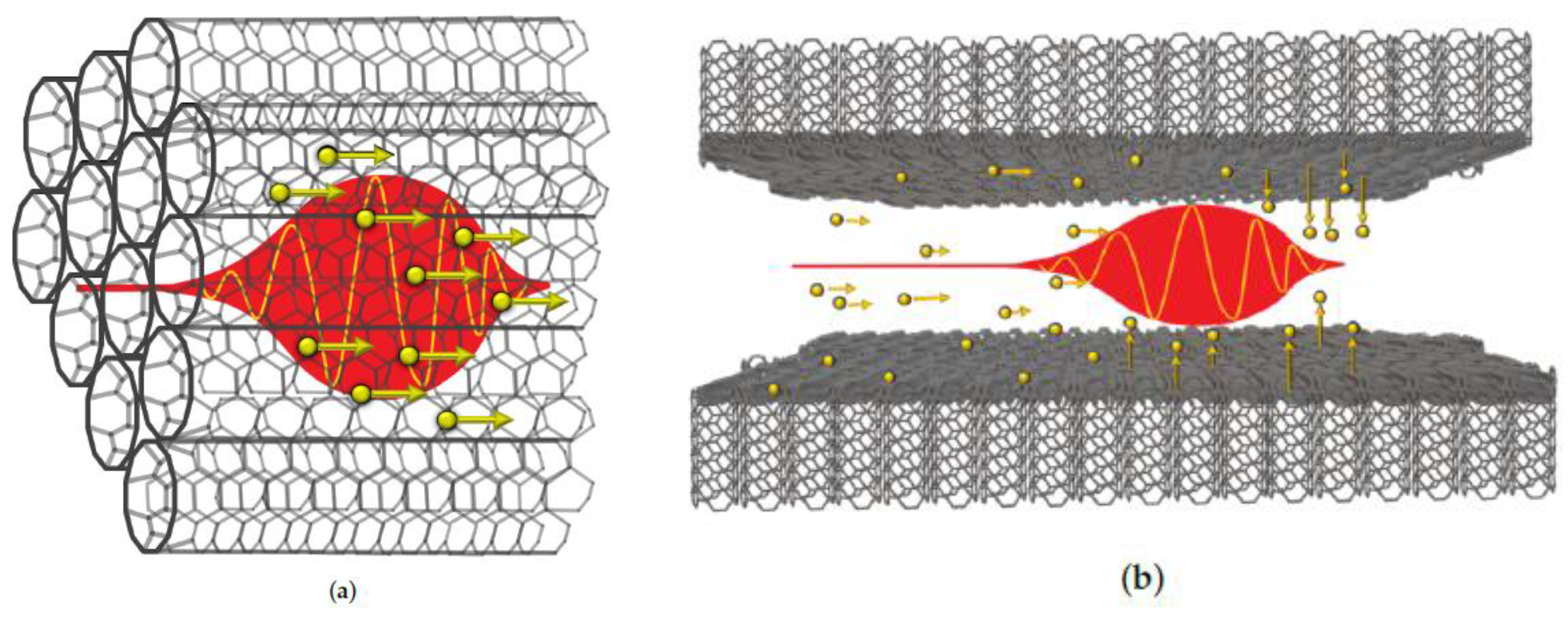
A brief illustration of the laser acceleration mechanism in CNT is given in
Figure 1. The wake-field excited by the laser is in the high-density regime of LWFA (the classical LWFA is in the low-density regime) and accelerates electrons to energies to the range from a few tens to a few hundreds of keV, which are sufficient to damage cancer cells locally but low enough not to cause collateral damage to healthy tissues.
LWFA transforms light energy from the high-peak-power laser pulse into the kinetic energy of accelerated electrons. The large gradients produced by the transverse laser intensity profile at focus and by the longitudinal temporal profile produce strong pondermotive forces, resulting in laser plasma wake-fields which accelerate electrons. The strength of laser wake field is determined by the driving laser’s peak intensity, defined by the peak power of the ultrashort pulses (temporal) and the focal profile (spatial). Laser intensity for electron acceleration in the high-density LWFA regime to attain electron energies from a few tens to a few hundreds of keV for endoscopic applications needs to be 10
14 W/cm
2 and higher [
7].
The field of compact Electron Accelerator is rich and full of creativity. Other approaches exist among which the dielectric laser accelerator (DLA) [
15] where an incident laser pulse is focused onto a nanofabricated accelerating structure, exciting traveling near-field modes. Electrons, propagating in close proximity to the structure, are accelerated when their velocity matches the phase velocity of one of the traveling modes, and they are injected into these fields at a particular time.
The dose (total electrons in treatment duration, e.g., seconds) required for each point of treatment is related to the average power of the excitation laser. With good efficiency in high-density LWFA, we expect that several watts of average power are sufficient. This power is readily available and thus our focus of the technology is on peak-power generation and delivery.
4. Fiber Laser Technology
It is interesting to note that our laser goal in this paper for the compact LWFA scheme, gigawatt, is the power level that the very first Chirp Pulse Amplification (CPA) demonstrated [
12]. Since then, CPA has propelled laser amplification to unprecedented level, and it is the technology used for all levels of LWFA today. We shall discuss the compact version of CPA system with fiber lasers reduced from the table-top lasers, much like table-top CPA lasers downsized the much larger laser systems otherwise.
This compactization comes from the progress in research and industry to the condensed forms of fiber lasers and diode lasers. Fiber laser takes a thin strand of optical fiber, active or passive, and a diode laser is built on a tiny yet powerful light-emitting semiconductor junction. Ultrafast fiber oscillators have been developed while amplification in fiber rely on the use of CPA. Advances of these “compressed” lasers are not only shown in academic research but also in rapid commercialization. We can see where the technologies are going, and they hold the promise leading to compact LWFA scheme for medical applications.
4.1. Fiber Laser Advantages and Characteristics
Fiber lasers have gain media confined within the core of an active optical fiber. Core diameter (more precisely mode-field diameter, or MFD) ranges from several μm to tens and hundreds of μm. Single-transverse mode MFD can be up to 100 μm. Pump laser diodes have emitters each sized from under an μm to several μm, with outputs coupled into the gain fiber. Pump intensity in the small cross-section of the fiber produces high inversion. Signal and pump in fiber propagate as guided wave permitting long interaction length in meters, yielding high conversion efficiency (more details in
Section 4.3). Fiber is flexible with typical bending radius of 20 cm or less, allowing fiber spooling in compact assembly. Heat dissipation is much more efficient compared to solid-state laser crystal due to the high surface-to-volume ratio of fiber and the distributed heat load along the length of the fiber. Besides, active fibers and passive fiber components and pump diodes can all be made from cost- effective scalable manufacturing.
There are two predominant fiber laser wavelengths in the industry, one is based on Ytterbium (Yb)- doped fiber operating slightly above 1 μm and the other Erbium (Er)- doped centered at 1.55 μm. Many Yb fiber lasers, operating in continuous-wave (CW) or Q-switch are used in metal cutting and welding and semiconductor processing. Ultrafast lasers utilize both Yb and Er doped fibers.
Fiber lasers with large cores (hundreds of μm) in multi-mode (MM) are used to produce kilowatt and higher power in CW. Beam quality is not optimal and M
2 is large but adequate for metal cutting and welding which do not require tight focusing. For diffraction-limited focusing, single-mode (SM) waveguiding is required permitting only the fundamental mode. Pump guiding is often in a double-clad configuration, allowing a larger guided pump core (which serves as inner cladding for signal) while the amplified signal light is in the smaller inner core. This results in brightness conversion from the pump to the laser. More details regarding the double-clad technology are discussed in
Section 4.3. Fiber lasers have the main advantages in producing high average power and high efficiency due to the fiber geometry of small cross-section and long interaction length. On the other hand, high peak-power lasers suffer detrimental nonlinear effects for the same reason. There are remarkable advances in making large-core (up to 100 μm) single-mode fibers to enable high peak-power amplification. The innate average-power advantage of fiber allows for high repetition rate of the amplified pulses.
We will, in this paper, only examine the peak power aspect of fiber systems for compact LWFA medical application. Available average power from fiber lasers typically exceeds requirement; for example, several watts of average optical power is abundant for endoscopic LWFA.
4.2. Efficient, Compact and Reliable Laser Diode Pumps
The overall high wall-plug efficiency and the compactness in fiber lasers are also attributed to semiconductor laser technology. An active laser diode emitter of a few μm wide and less than 1 μm thick can produce for example 10 watts of power, for example Quantum-well design of direct band-gap semiconductor laser diode and the choice of material systems (III-V and II-VI, each has subsets) cover emission wavelengths essentially across the visible and near infrared spectrum. Diodes from 920 nm to 980 nm are used for pumping Yb or Er-Yb fibers; 980 nm or 1480 nm pumping Er fibers. Diode pumps have electrical to optical efficiency from 50% to 70% in literature [
16] for example and in product catalogs from commercial diode manufacturers [
17,
18,
19] including the loss after assembled into fiber-coupled packages in research literature and also in commercially available products.
The research and industry have achieved extraordinary reliability over the years, from the first lab diode laser that lasted for milliseconds to those used in submarine fiber-optic link today with millions of hours of mean-time-between-failures. These are all remarkable that current density in the diode junction and optical facet power density are at the levels of 10 kA/cm2 and 100 MW/cm2. Today, a typical single emitter at 10 W is rated for tens of thousands of hours. Lifetime can be prolonged at de-rated power levels.
4.3. Double-Clad Fiber as Brightness Convertor
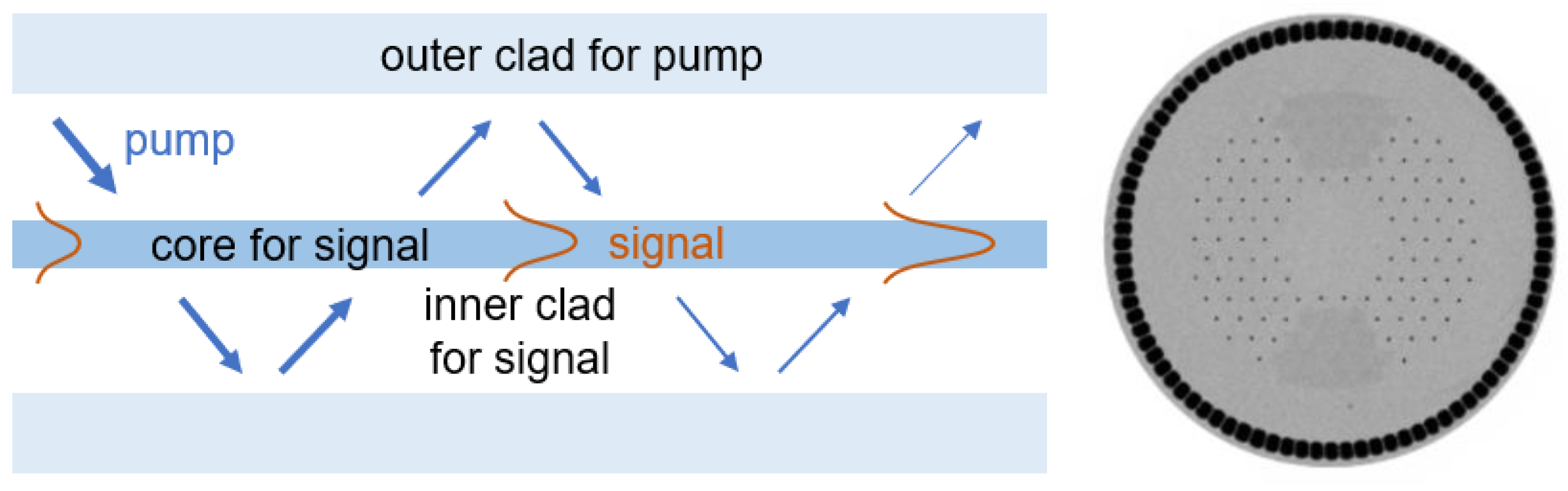
Double-clad fiber technology enables high power and high efficiency in fiber laser operation. Light to be amplified is in the inner core while pump light is guided in the larger pump core. The middle portion in turn serves as the cladding of the signal. Pump is confined by the outer cladding. Design of the double-clad structure introduces features to allow sufficient crossing of pump in the signal core. See
Figure 2 for illustrations. Meters-long interaction length allows for a high pump absorption efficiency of 90%. Fiber conversion efficiency from pump power is in the range from 50% to 70% in commercially available double-clad fiber products [
20,
21,
22,
23] depending on pump wavelength which determines quantum efficiency.
The larger pump guide is substantial in gathering pump power from broad-area MM laser diodes. Thus, double clad fiber is seen as a brightness up-converter from the lower intensity of pump light to higher intensity of the laser light in the inner core. Several pump modules can be combined in a fiber combiner for more pump power while maintaining each pump module at moderate power for long-term reliability.
A more advanced double-clad fiber design utilizes an air clad as the outer clad for the pump (
Figure 2). The low index of air holes provides much higher index contrast, facilitating high numeric apertures (0.4 to 0.6) to couple in even more divergent pump light.
4.4. CW and Nanosecond Fiber Lasers
Fiber laser and laser diode industries have seen unprecedented progress in the last few decades. For example, fiber lasers of refrigerator size (mostly electrical and cooling), can deliver tens of kilowatts of CW power while keeping component damage under control. These fiber lasers are expanding the capabilities of other lasers, with the sheer light power to convert to high heat. Beam quality is often far from diffraction limit. Because of this, kW CW lasers typically have moderate focused intensity (
Table 1 below).
Nanosecond fiber lasers from Q-switched operation can be used in semiconductor wafer and chip processing. There are designs in SM or MM, depending on the needed spatial precision. These lasers have nanosecond pulse duration boosting laser peak power and intensity (
Table 1) which can be viewed as the intermediates between CW and ultrafast fiber lasers in peak power and intensity.
5. Ultrafast Fiber Lasers and Amplifiers
Ultrafast fiber lasers soon followed the advent of mode-locked femtosecond dye lasers in 1980s and have seen rapid expansion in R&D and commercialization. As of 2020, there have been 5000 publications on ultrafast fiber lasers [
25].
Having 100 μJ pulse energy with sub-picosecond width delivers hundreds of megawatts peak power (
Table 1 above). Focused pulses have light intensity which corresponds to electric field strength greater than molecular bonding force. At several hundred femtoseconds, a laser pulse is shorter than phonon scatter time in solids; thus, there is no heat transferred from the laser. Such conditions create cold ablation or photoionization [
26]. Micro-machining applications are enabled where hard materials—such as glass or sapphire—can be cut with superior quality; for example, in fabricating smart-phone screens.
Our application, laser-wake-field acceleration in endoscopic oncology, acquires tens of keV electron energy from laser pulses at intensity starting from 10
14 W/cm
2 [
7]. This intensity can be produced by focusing a gigawatt laser (
Table 1 above) to a moderate focal diameter such as 20 μm. We now discuss the technologies leading to gigawatt fiber lasers.
Most ultrafast fiber system (or in general high peak-power lasers) are configured in a master-oscillator-power-amplifier (MOPA) architecture. An ultrafast fiber oscillator provides stable seed pulses of femtoseconds or picoseconds. Prior to amplification, the pulse repetition rate is often reduced. Power amplifier(s) then concentrate laser energy to the fewer selected pulses and increase peak power by many orders.
5.1. Ultrafast Fiber Laser Oscillator
Nature has offered mechanisms of organizing broad spectral bandwidth in laser media into ultrashort pulses in time. In the early 1980s, colliding pulse mode-locking was discovered in dye lasers [
27,
28] using saturable absorbers. The first-ever femtosecond pulses were generated, opening the ultrafast time scale. Kerr-lens mode-locking in Ti:Sapphire lasers were later revealed and developed [
29]. Around the same time, mode-locked femtosecond fiber lasers were reported [
30]. Mode-lock mechanisms shaping laser light into ultrashort pulses are based on one type or another of nonlinear optical processes.
Advances in ultrafast fibers are reviewed by a number of excellent papers for example [
25,
31,
32]. Many ultrafast fiber oscillators are mode-locked or aided (start action and stabilization) by saturable absorption and the mechanisms alike. Saturable absorption is a nonlinear process in which the lower intensity of a pulse’s pedestals or wings is absorbed to a greater extent than the peak. Repetitive laser action shapes random waveform into pulse of short duration supported by laser gain bandwidth. Semiconductor, carbon nanotube [
33] and other materials can be made of this function. Semiconductor saturable absorber mirror (SESAM) [
34] is often used in mode-locking ultrafast lasers. Other effective saturable mechanisms—such as nonlinear polarization evolution (NPE) and nonlinear amplifying loop mirror (NALM) [
30,
35]—also function very well.
Ultrafast fiber lasers also have to deal with large amounts in nonlinearity and group velocity dispersion (GVD) due to small mode area and long propagation length. These factors can either benefit pulse shaping or have detrimental effects. Silica fiber has normal GVD at 1 μm (Yb gain region) and is anomalous at 1.5 μm (Er region). A laser cavity can be configured in a net dispersion of either way. Soliton lasers take advantage of the soliton mechanism in balancing self-phase modulation (SPM) and anomalous dispersion [
36,
37]. Pulse energy in soliton fiber lasers is typically low. In the normal dispersion regime, similariton is effective in producing higher energy pulses, where the interplay of dispersion, SPM, and gain renders an input pulse of arbitrary shape evolving asymptotically into an amplified, linearly chirped pulse. The pulse grows in duration, spectral width, and peak power in a self-similar manner to that the temporal profile and the chirp rate remains unchanged [
25,
38,
39]. Chirp can be externally compressed. Additional techniques—such as spectral filtering and polarization control—can also be useful to assist the mode-locking [
40].
Robustness of well-designed femtosecond fiber lasers has been established. For example, in the SLAC National Accelerator Laboratory’s Linac Coherent Light Source, the injector ultrafast laser system has an Yb ultrafast fiber laser as its source. Up-converted UV pulses from this femtosecond laser system emit photoelectrons in the injector photocathode. Synchronized electrons are accelerated by the linear accelerator to generate femtosecond X-rays in the free-electron laser section [
41].
5.2. Ultrafast Fiber Amplifiers
Packing a gigawatt laser into a fiber laser system has many challenges. Intensity of short pulses in fiber is inherently high. Nonlinear (non-recoverable) phase accumulation can quickly deteriorate the spectral and temporal profiles as the pulse propagates. When the pulse gains intensity above the material damage threshold, it damages or vaporizes the fiber.
Two major technologies are the key enablers to overcome the obstacles: chirped-pulse amplification (CPA) helps to boost amplifier output peak power by 3 to 4 orders, while large mode area (LMA) fibers increase by another 2 to 3 orders.
5.2.1. Chirped-Pulse Amplification
CPA proceeds in three steps: (1) an ultra-short laser pulse is stretched in time by several orders of magnitude, so that its peak power is correspondingly reduced, (2) it is amplified in a laser material without damaging it, (3) it is compressed in time back to its original duration, resulting in very high peak power [
11].
Light amplification by stimulated emission preserves the optical phase. Pulse stretched into a linear chirp prior to amplifier is a reservable process by the corresponding compression after amplification.
5.2.2. Large Mode Area Fiber
Increasing the mode-field diameter (MFD) in the amplifying fiber is another key to mitigate the peak power problem [
39,
42]. In doing so, single mode must be maintained. Modal dispersion in multi-mode propagation obliterates temporal profile of the pulses. Furthermore, the fundamental mode allows diffraction-limited focusing for the targeted intensity. SM fiber designs with step-index or graded-index profiles are limited due to the small index contrast and the simple spatial profile. Breakthrough in photonic crystal fibers (PCF) makes large-mode-area single-mode fiber design possible and enables much higher peak power in ultrafast fiber amplifiers, in conjunction with CPA.
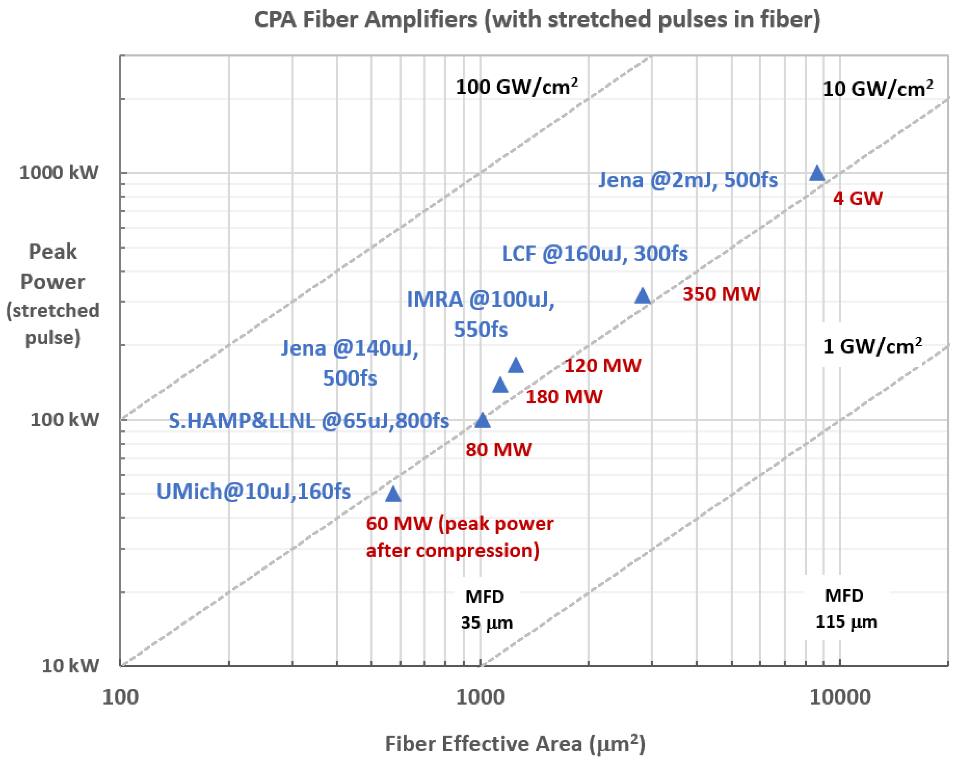
PCF guiding employs periodic index modulation with air holes to achieve high index contrast. Preferential design in the cladding discriminates high-order modes allowing single mode with larger core sizes (see
Section 7.1). Commercial PCF fibers with MFD over 30 μm are now available. As evident in Figure 3, fiber amplifier output peak power level goes hand-in-hand with mode-field area. In the fiber system producing 4 GW, the final amplifier stage employed a PCF Yb gain fiber with 105 μm MFD [
43].
5.3. Towards Gigawatt
In
Figure 3, a survey of high-power ultrafast fiber laser research in last 15 years is presented. Even with this limited survey we can see the extraordinary advances in laser peak power from tens or hundreds of megawatts to gigawatts. As remarked earlier, the first CPA gigawatt system was based on table-top solid-state lasers with free-space optics. Now gigawatt can be condensed to a fiber laser system. Gigawatt fiber lasers enable compact, portable LWFA medical applications.
5.3.1. Limitation due to Fiber Nonlinearity
Over the length L in fiber, nonlinear phase is accumulated from the small but existent nonlinearity index (3 × 10⁻¹⁶ m2/W in silica),
where
is effective mode-field-area.
P is the peak power of the pulse averaged over the fiber length, already reduced by the stretch ratio from CPA.
L is typically of meters.
can be also viewed as proportional to the light intensity
in fiber.
As a rule-of-thumb estimate, acceptable (or B integral) is about . Above this level, non-correctable detrimental effects are seen on temporal and spectral quality of the pulse. This obstacle is seen at lower intensity levels in fiber amplifiers, compared to solid-state lasers.
Note that the blue triangle data points in
Figure 3 are “pushed” along the intensity line of 10 GW/cm
2, indicative of the limit imposed by nonlinear phase accumulation. Further increasing the fiber mode area is becoming more difficult. MFD of 100 μm is already 100 times that of the laser wavelength. With large core diameters, single-mode guiding becomes highly sensitive to fiber bending. In fact, some of the large-core fibers are the rod-type fibers.
5.3.2. Summary
Gigawatt ultrafast amplifier systems are empowered by the two key technologies:
CPA reduces P by 3 to 4 orders by stretching the seed pulse prior to amplification.
Large-mode-area fibers increase mode area A, thus reducing light intensity by 2 to 3 orders.
As efforts continue to drive fiber lasers to higher peak power, coherent combination of many ultrafast fiber lasers is seen as the next frontier [
44,
45]. Progresses and highlights are reported in the next section. The state-of-the-art takes fiber lasers beyond gigawatt and open a new array of capabilities in bringing on “digital laser” applications.
6. Coherent Beam Combining (CBC) Lasers
Coherent beam combining (CBC) introduces a paradigm shift in laser architecture offering major opportunities for laser design and consequently for applications. CBC can be seen as the space domain equivalent to what CPA allows in time domain: spreading the energy prior to amplification to mitigate limitations such as B integral. CBC consists indeed in the spatial splitting of an initial laser beam into N small aperture sub-beams followed by subsequent recombination of the amplified beams. The above-mentioned limitations (
Section 5.3) remain valid at each individual fiber level but are overcome at a global scale if the N amplifying channels are ultimately successfully coherently combined. Gigawatt ultrafast fiber systems can then be empowered by a third key technology (from
Section 5.3.2):
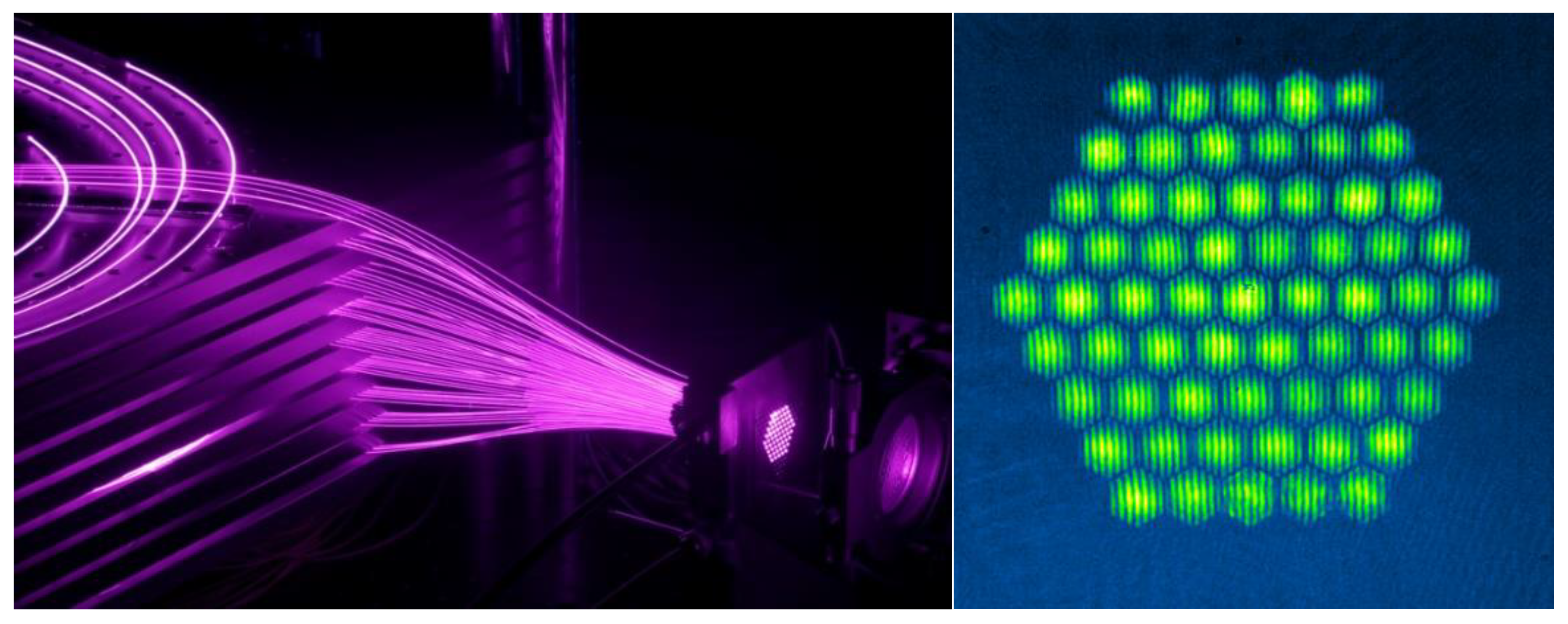
Figure 4 illustrates Ecole Polytechnique/Thales N = 61 channel XCAN CBC prototype (with η experimentally ranging from 40% to 50%) [
46].
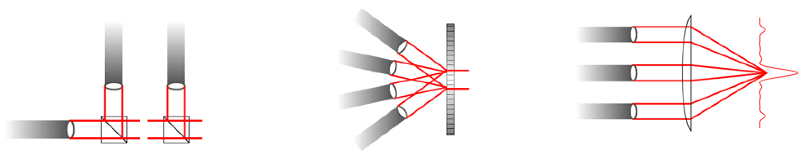
XCAN relies on far field CBC (also described as tiled-aperture CBC), a combining approach inherently limiting the efficiency to η = 65% theoretical value but offering two experimental key advantages: absence of a final optic dealing with the full combined peak and average power (see
Figure 5) and near field access to individual control of phase, amplitude and polarization for digital laser applications [
47,
48].
Alternative architectures falling into the near field combining category (also described as filled-aperture CBC) does not face such an efficiency limit with experimental η only limited by optics quality (generally above 90%). Recently, 81 beams have recently been combined with a diffractive combiner [
49] whereas 16 amplifying channels were combined with beam splitters [
50]. More recently, the same group achieved a similar channel number coherent addition within a single multicore fiber [
51], paving the way for even more compact (even though the involved fiber was not flexible) laser system. Each core has a diameter of 19 μm with a pitch of 55 μm between the core centers.
7. Photonic Bandgap Fiber (Hollow-Core Fiber) for Pulse Delivery
Fiber amplifiers capable of producing gigawatt peak power are proven, further enhanced by coherent beam combining lasers that push beyond gigawatts and are capable of shaping user-desired wavefronts. Compact fiber laser sources are here for LWFA medical applications. In endoscopic applications, laser pulses need to be delivered with flexible channel to the LWFA cell near the treatment site. We look to the hollow-core fiber technology for carrying the intense gigawatt peak-power laser pulses. Light propagation is mostly in the hollow core made of air. In this way, material damage is avoided; nonlinearity and dispersion can be drastically reduced.
Hollow-core fiber stems from the advents of photonic crystal fiber (PCF) technology. PCF technology pushes fiber design well beyond what conventional step-index fibers can do. It branches into two distinct mechanisms: high-index guiding and low-index guiding. Large-mode- area fibers enabling ultrafast fiber lasers are based on high-index guiding PCFs and hollow-core fiber belongs to low-index guiding.
7.1. High-Index Guiding PCFs
Conventional step-index fibers utilize total internal reflection (TIR) to guide light rays, having higher optical index in the core than in the cladding. This index contrasts (with converging power) shapes collective wave-guiding by balancing natural light diffraction in the fiber. Proper single-mode fiber design is to have only the fundamental mode. PCFs greatly broaden the limited design capabilities with step-index fiber design.
PCFs have a sophisticated microstructure of different refractive indexes [
24,
52]. They are typically glass fibers fabricated by pulling from a preform in a furnace—like conventional fibers—and they maintain bending flexibility. The background material is often undoped silica and low index regions are typically air voids. Air has the lowest optical index, thus producing very high index contrasts. Stronger guiding results from this modified total internal reflection (M-TIR) [
52]. Locations of air-hole networks can be arranged according to desired function, such as mode-guiding differentiation, dispersion, and cut-off wavelength (or the absence of it).
PCFs allow a new range of novel properties. The large-mode-area (LMA) PCF is an essential element in ultrafast fiber amplifiers for reducing intensity. In a commercial offering of an Yb-doped fiber, for example, using precise control of airhole diameter and spacing and induced birefringence yields a single mode polarizing fiber with diffraction-limited beam quality at 40 μm diameter core size (see
Figure 2, the shape on the right).
Another example of PCF having the opposite function of large-mode-area fibers is the highly nonlinear fiber for supercontinuum generation. The small-core (1 or 2 μm) fiber sharply increases the light intensity, and the near-zero-dispersion design allows long interaction length without dispersing the femtosecond pulses. The resultant supercontinuum spans over an octave wide in frequency, allowing f-to-2f interferometry for carrier-envelop-phase stabilization in the laser oscillator. The accomplished system generates phase-synchronized frequency comb in high-precision metrology applications [
53].
7.2. Hollow-Core Fiber (Low-Index Guiding) for Ultrafast Pulse Delivery
Low-index-guiding PCFs uses photonic bandgap (PBG) effect to guide light. The guiding mechanism in PBG fiber is fundamentally different from high-index guiding in M-TIR. The light is typically confined to the empty core such as air while the surrounding microstructure region as the cladding displays a photonic bandgap [
54]. Much like electron waves in a crystal where a band of electron wavevectors is forbidden, optical waves of certain wavelengths in the photonic bandgap cannot propagate. Therefore, light is trapped and propagates only in the hollow core surrounded by the anti-resonant (being reflective) microstructure. Only the edge of the transverse profile (less than a few percent of the light power) sees the glass material.
PBG fiber is a new paradigm in fiber design. Nature has existing examples of the PBG effect; for example, the color of a butterfly is the result of anti-resonant nano-cavities at the reflecting wavelength. Dispersion of PBG fibers can be tailored as it is mostly determined by the microstructure. PBG fiber design is sophisticated, which requires full vectorial calculation from Maxwell Equations. Mechanically PBG fibers are also flexible.
With light being guided in the hollow core of air, vacuum, or gas, the high-intensity ultrafast laser pulses do not experience nonlinearity (and damage) as in the solid core fibers—facilitating fiber delivery applications with ultrafast pulses. For example, high-harmonics generation (UV) from laser pulses can be generated at the end of the delivery fiber as UV light darkens fiber. Ophthalmology surgery can be performed with the laser delivered by the hollow-core fiber. This is also what is needed in endoscopic LWFA.
Capabilities of hollow-core fibers are given in a couple of demonstrated results. In the first result [
55], 70 W of average power of picosecond pulses are transmitted over the hollow-core fibers with only a few percent power loss after 5-10 meters. Diffraction-limited beams in MFD of 8 μm, 13 μm, and 22 μm fibers are delivered while bending radii are kept at 8 cm. Another demonstrated result [
56] is the hollow-core fiber with a MFD of 40 μm. It has the capacity to carry 500 fs pulses of 500 μJ energy. This amounts to 1 GW of peak power. The bending radius of the fiber is about 25 cm. Ultimately, hollow-core fibers are limited due to damage of the glass structure at the edge of the laser intensity profile.
7.3. Additional Delivery Capability
The limit of hollow-core fiber transmission is affected by damage at the edge of the intense laser mode profile. To further increase delivery capability, we may anticipate the coming of a multi-hollow-core fiber. There are multi-core fibers existent today based on step-index solid materials. This type of design has multiple cores with a common outer wall, protection coating, enforcement, etc. It has been developed as a compact form for space-division multiplexing in optical communication to multiply the data-carrying bandwidth. Similarly, we may boost throughput of laser pulses with multiple hollow cores in a common fiber structure. Laser channels in the close spatial vicinity help to facilitate a common focal point with the use of a lenslet array for collimation prior to a common focusing lens. It is similar to CBC lasers (see
Section 6) in spatially combining beams, but without phase locking. Power addition is not coherent thus intensity distribution varies from shot-to-shot within the focal boundary. Effectiveness of such a laser field in LWFA requires further study.
8. Applying Ultrafast Fiber Technologies to Endoscopic LWFA
One promising avenue of cancer treatment is brachytherapy, in which a source of radiation is brought inside the body close to the tissues requiring treatment. For endoscopic and intraoperative brachytherapy at the local treatment site, electron radiation from few tens to few hundreds of keV can be effective (see brief introductions in see
Section 1 and
Section 6). Laser intensity for electron acceleration in the high-density LWFA regime for endoscopic applications needs to be 10
14 W/cm
2 and higher. In this paper, we have brought forth ultrafast fiber technologies for this application: ultrafast fiber lasers (single-fiber system or coherent-beam-combining lasers) which are capable of generating gigawatts and above as the light source, and hollow-core fibers for delivering these intense laser pulses endoscopically.
Laser pulses are delivered flexibly to the LWFA cell and ready to focus on to the target material to generate and accelerate electrons. Engineering design must be mindful of damage in the delivery optics due to the nature of the intense laser pulses. For such the laser beam after exiting the hollow-core fiber should be expanded to encounter optics based on solid material. Furthermore, the expanded beam is necessary for the proper beam size to optimize diffraction-limited focusing to the target. The choice of focusing design also depends on the Rayleigh range needed for LWFA. At a modest 20 μm focal diameter, Rayleigh range is about 300 μm for laser wavelength of 1 μm; 1 gigawatt peak power will yield W/cm2, in range for target LWFA laser intensity.
An effective scheme of LWFA utilizing the relatively low laser intensity of
W/cm
2 is the plasma beat-wave accelerator (PBWA) [
7,
57]. The scheme uses two co-propagating laser pulses with two optical frequencies—
and
—and the beat gives a modulated laser amplitude for the resonant excitation of a plasma wave at
where
is the plasma frequency. The modulated laser intensity profile which is resonant with plasma wave gives in-phase pondermotive kicks to accelerate the electrons. The advantage of PBWA is that lower peak power and longer laser pulses from the fiber lasers can be used. We may choose two common fiber laser wavelengths of 1.03 μm and 1.56 μm respectively for the two laser frequencies of
and
. Reference [
7] has more discussion and data about electron energy spectrum, plasma frequency related to this setup and application.
Since hollow-core fiber is anti-resonant design to specific wavelength (or to the specific photonic bandgap), a single hollow-core may not support the transmission of both wavelengths for the generation of the plasma beat wave. In that case, two hollow-core fibers for the respective wavelengths can be employed and are brought together at a common focus for the PBWA.
9. Summary
The ultrafast fiber lasers discussed in this paper may be used or combined into a system of fiber lasers, together with hollow-core fiber delivery as a converged technology to be applied in the use of high-density LWFA and its applications to endoscopic cancer therapy. Ultrafast fiber laser technology of today is capable of generating gigawatt peak-power for the compact LWFA and is further enhanced by coherent-beam-combining of multiple fiber lasers. Hollow-core fibers make it possible to flexibly deliver the intense pulses that conventional fibers cannot. These technologies pave the way in realizing the potential of compact and practical laser wake-field applications to oncology.


