Article

Wavelength-Tunable Optical Two-Tone Signals Generated Using Single Mach-Zehnder Optical Modulator in Single Polarization-Mode Sagnac Interferometer

1
Faculty of Science and Technology, Gunma University, Kiryu-shi 376-8515, Gunma, Japan
2
Graduate School of Science and Technology, Gunma University, Kiryu-shi 376-8515, Gunma, Japan
*
Author to whom correspondence should be addressed.
Photonics 2022, 9(3), 194; https://doi.org/10.3390/photonics9030194
Submission received: 20 January 2022 / Revised: 21 February 2022 / Accepted: 8 March 2022 / Published: 17 March 2022
(This article belongs to the Special Issue Photonics for Emerging Applications in Communication and Sensing)

Abstract

:
We demonstrate 60 GHz separation optical two-tone signal generation at arbitrary C-band wavelengths without involving complicated optical wavelength filtering. By utilizing a polarizer, the selective suppression of undesired low-order optical sidebands has been proven and optimized based on model analysis. By utilizing this scheme in conjunction with the optimized parameters, more than 20 dB of suppression of undesired optical sidebands have been successfully achieved over a 40 nm wavelength range. This scheme allows us to generate optical two-tone signals at the desired wavelength.

1. Introduction

A phase-synchronized pair of monochromatic lightwaves with stable frequency spacing plays an important role in the complementary use of radio-wave (RF) signals and lightwaves, i.e., in the field of microwave photonics. Such a lightwave-pair is called as an optical two-tone (OTT) signal. Since the RF signal obtained from the direct detection of the OTT signal has a stable frequency, this can be applied to the convergence of optical and wireless communications [1], high-resolution-image broadcasting [2], precise clock distribution [3,4], radar measurement [5], and THz signal generation [6]. Not limited in the complementary use of an RF signal and lightwaves, some advantages are there in RF frequency upconversion, such as low phase noise, frequency tunability, increase in the output signal frequency and allowance of some optical techniques such as optical amplification.
Wide frequency-separation OTT signals are especially useful because of the demand for millimeter-waveband RF signals; therefore, several types of OTT signal generation schemes have been explored. One involves constructing a phase-locked loop for lightwaves [7]. Its offset range currently reaches 17.8 GHz [8] due to phase noise (linewidth) suppression of the semiconductor lasers constituting the optical phase-locked loop. However, a significant problem remains in further increasing the bandwidth: it requires broad loop-BW, which implies that the closed-loop should be as short as possible. In contrast, there is another approach that employs optical modulation to generate optical sidebands [9], which is facilitated by the development of a waveguide-type optical modulator equipped with traveling-wave electrodes [10,11]. In this scheme, the optical frequency spacing of the generated OTT signals is mainly dominated by the driving frequency of the optical modulator, and it can be exceeded by extracting a pair of higher-order optical sidebands generated by deep optical modulation.
Several approaches have been demonstrated for sideband extraction. The straightforward way is to filter an optical signal in the wavelength domain [12,13,14], which involves the precise adjustment of transmission/rejection wavelength ranges when the wavelength of the OTT signals should be changed. Additionally, their optical-frequency separation is limited by the steepness of the optical filter in the wavelength axis. The other approaches are investigated using a modulation order-dependent interference by utilizing an I-Q optical modulator [15,16,17] and periodic phase shifts of each optical sideband given by RF signals; the desired optical sidebands survive to become OTT signals via constructive optical interference, while unnecessary optical sidebands disappear due to the destructive optical interference [18,19,20]. The approach is an optical filter-free operation, allowing for the optical wavelength flexibility to endure. However, the optical phase offset must be specifically stabilized to achieve low-spurs operation in long term, and an optical modulation device should be densely integrated to increase the degree of frequency multiplication (i.e., the ratio of frequency spacing of OTT signals against the frequency of the RF signal driving the optical modulator). Although densely-integrated optical modulation devices have been reported [21,22,23,24,25], further dense integration would be limited via a fabrication process and physical parameters such as wavelength of the lightwave and refractive indices of materials.
Another approach involves using the polarization of light as one degree of freedom. While some attempts were conducted using a polarization modulator in a polarization-maintaining Sagnac interferometer (PMSI) [26,27], one of the issues was stability degradation. In these approaches, BOTH polarization modes of PMSI were utilized, so that the output signal would be unstable due to a fluctuation in polarization by temperature via retardation in optical fibre. Deviation of the bias voltage of the polarization modulator would also induce degradation of its performance. A system for stabilizing static optical phases must be required, as well as the approaches based on an integrated optical modulator. Furthermore, the analytically obtained optimization results were complicated.
These problems have been solved using a configuration where a bi-directional single Mach-Zehnder optical modulator (MZM) is nested in only ONE polarization mode of the modified PMSI [28,29,30,31]. In this article, we describe how this approach allows us to generate OTT signals at arbitrary wavelengths. Our scheme promises wavelength tunability and simplicity; it only requires wavelength changes for the seed lightwave of the OTT signal generator, and it is free from the precise adjustment of an optical band-rejection filter. In Section 2, the operation principle is described by introducing an analysis model to derive an equation of an output lightwave signal from the proposed configuration. The analytical results are also discussed. In Section 3, we describe a proof-of-principle experiment. Based on the obtained optical spectra and their derivatives, we show that this scheme is suitable to generate the OTT signals for C-band wavelengths. In Section 4, we summarize the OTT signal generation scheme.

2. Principle

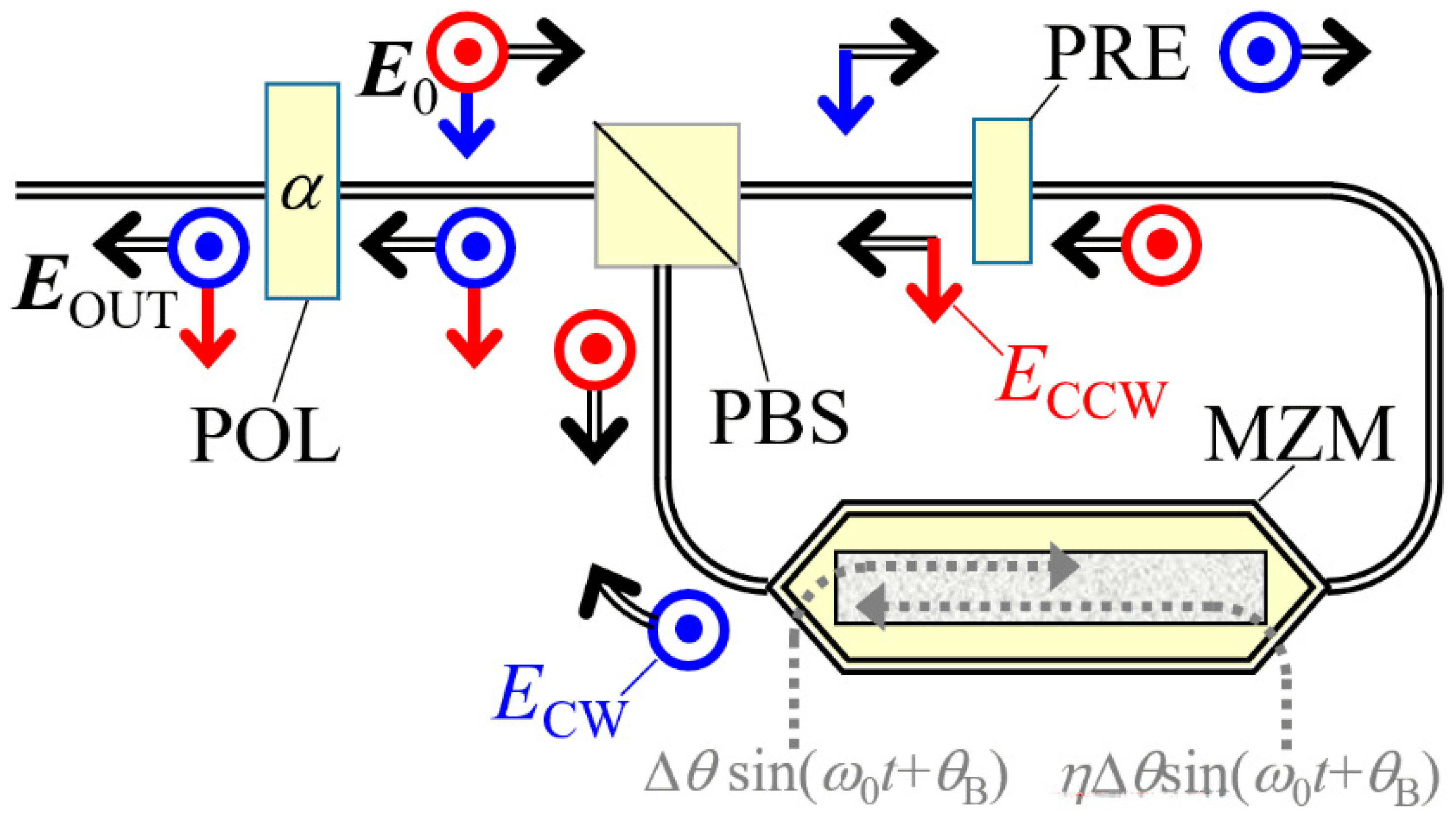
2.1. Output Signal from Polarization-Maintaining Sagnac Interferometer

Figure 1 shows a model for generating wavelength-tunable optical two-tone signals, which is composed of a push-pull-driven MZM within one mode of a PMSI [30,31]. In this setup, P-polarized incident lightwaves propagate in the clockwise direction, while S-polarized ones propagate in the counter-clockwise direction. Due to the polarization-rotation element (PRE), both components become S (TE) polarized at the MZM. Incident lightwave E0, composed of the P-polarization component E0P and S-polarization component E0S, is described as
E 0 = [ E 0 S E 0 P ] = [ E 0 cos α E 0 sin α ]
where α is the angle of the polarizer placed at the input port of polarizing beam splitter (PBS), and E0 is the lightwave amplitude just after passing through the polarizer. Hereafter, the polarization-extinction ratio (i.e., the inverse of attenuation of the polarization component when the insertion loss of the polarizer is omitted) is denoted as ξ, while in Equation (1) the effect of the polarization extinction ratio is omitted because the dominant term of each polarization component belongs to its polarization axis. The lightwaves after passing through the MZM and PRE become
E CCW = [ 0 T MZM ( Δ θ ,   θ B ) E 0 S ] = [ 0 T MZM ( Δ θ   ,   θ B ) E 0 cos α ]
and
E CW = [ T MZM ( η Δ θ ,   θ B ) E 0 P 0 ] = [ T MZM ( η Δ θ ,   θ B ) E 0 sin α 0 ]
for counter-clockwise propagation ECCW and clockwise propagation ECW, respectively. Here, we assume that the polarization extinction ratio of the PBS is infinite; however, the effect of its finite polarization extinction ratio results in lightwave power loss due to leakage at the empty port of the PBS in the PMSI. Note that, at the PRE, the P-polarized lightwave is converted into an S-polarized one, and vice versa. TMZMθ, θB) is the transmittance of the MZM that is driven by a sinusoidal RF signal with an angular frequency of ω0 and induced optical phase Δθ, which is given by
T MZM ( Δ θ ,   θ B ) = cos ( Δ θ sin ω 0 t + θ B ) ,
if the insertion loss of the MZM is omitted. θB is the phase bias of the MZM, and hereafter θB is assumed to be π/2; i.e., the MZM is driven under the null-bias condition. η is the ratio between the two induced optical phases, and |η| is assumed to be less than 1. So, the attenuation of the RF signal amplitude to achieve the ratio is 1/|η|. In Figure 1, a set of induced optical phases (Δθ and ηΔθ) is independently shown, but actually, the set can beprepared by utilizing RF signal reflection or circulation. Adopting the MZM possessing RF termination ports, we can simultaneously induce two optical modulations with different modulation indices [29]. Using this feature, we modulate the two circulating lightwaves independently, with modulation indices of Δθ and ηΔθ for ECCW and ECW, respectively.
At PBS, these lightwaves are combined and projected onto the polarizer. The lightwave, after passing through the polarizer, EOUT, can be described as
E OUT = T POL [ E CCW + E CW ] = [ cos α sin α sin α cos α ] [ 1 0 0 1 / ξ ] [ cos α sin α sin α cos α ] × [ T MZM ( η Δ θ ,   θ B ) E 0 P T MZM ( Δ θ ,   θ B ) E 0 S ] = E 0 sin 2 α 2 { T MZM ( Δ θ ,   θ B ) + T MZM ( η Δ θ ,   θ B ) } × [         cos α sin α ]   + E 0 ξ { T MZM ( η Δ θ ,   θ B ) sin 2 α T MZM ( Δ θ ,   θ B ) cos 2 α } × [ sin α cos α ] ,
where the first and second terms correspond to the lightwave amplitude parallel and perpendicular to the axis of the polarizer, respectively. TPOL is the amplitude transmittance of the polarizer:
T POL = [ cos α sin α sin α cos α ] [ 1 0 0 1 / ξ ] [ cos α sin α sin α cos α ] .
If the orthogonal axis of EOUT is chosen to be parallel and perpendicular to the polarizer, the lightwave EOUT can be expressed as
E OUT = T POL [ E CCW + E CW ] = [ 1 0 0 1 / ξ ] [ cos α sin α sin α cos α ] [ T MZM ( η Δ θ ,   θ B ) E 0 P T MZM ( Δ θ ,   θ B ) E 0 S ] = E 0 [ sin 2 α 2 { T MZM ( Δ θ ,   θ B ) + T MZM ( η Δ θ ,   θ B ) } 1 ξ { T MZM ( Δ θ ,   θ B ) cos 2 α T MZM ( η Δ θ ,   θ B ) sin 2 α } ] .
The lightwave coming back to the polarizer from the PMSI is projected with a different angle, −α.

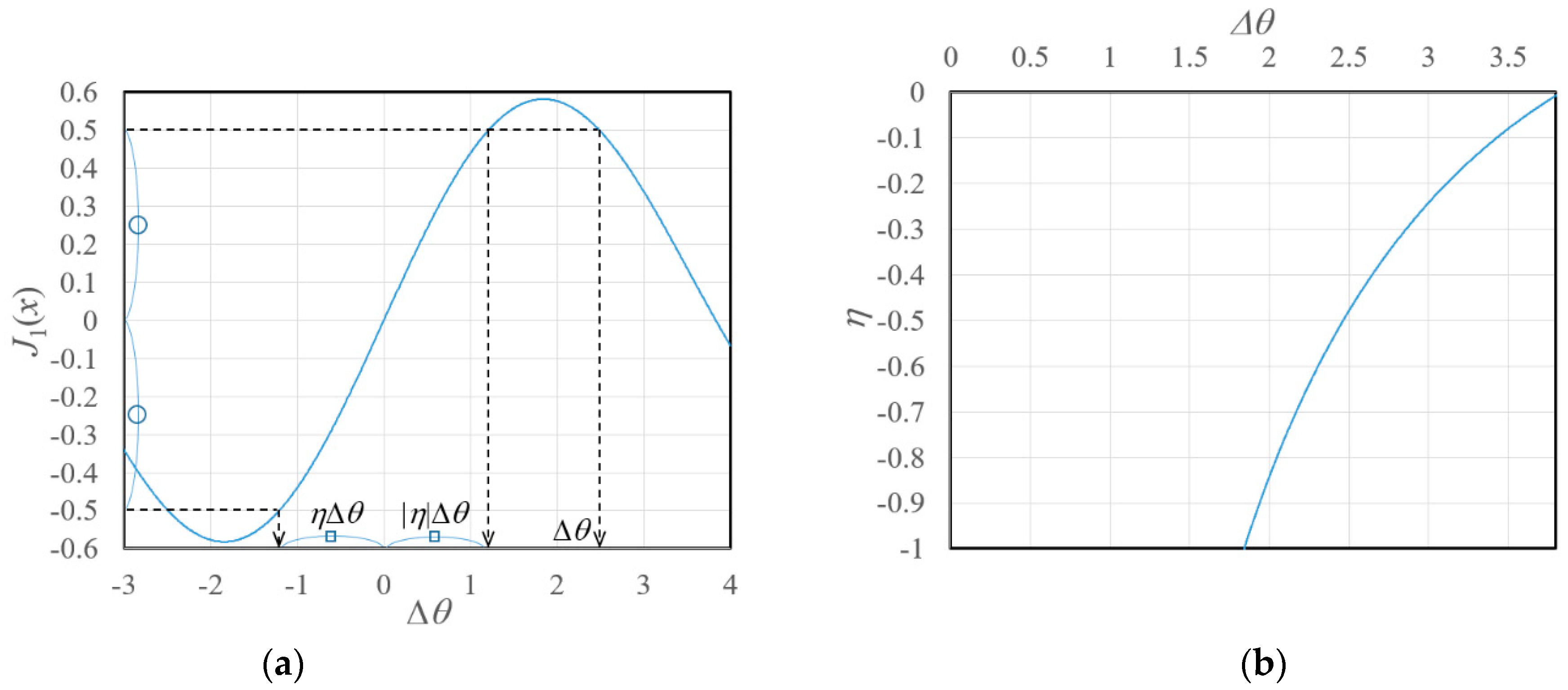
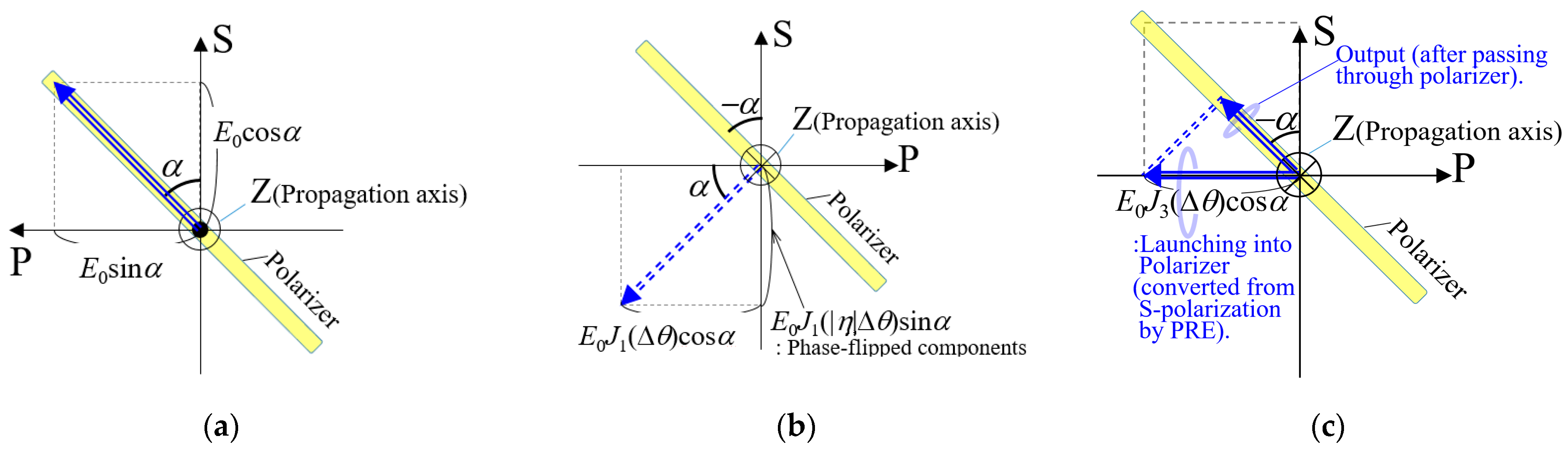
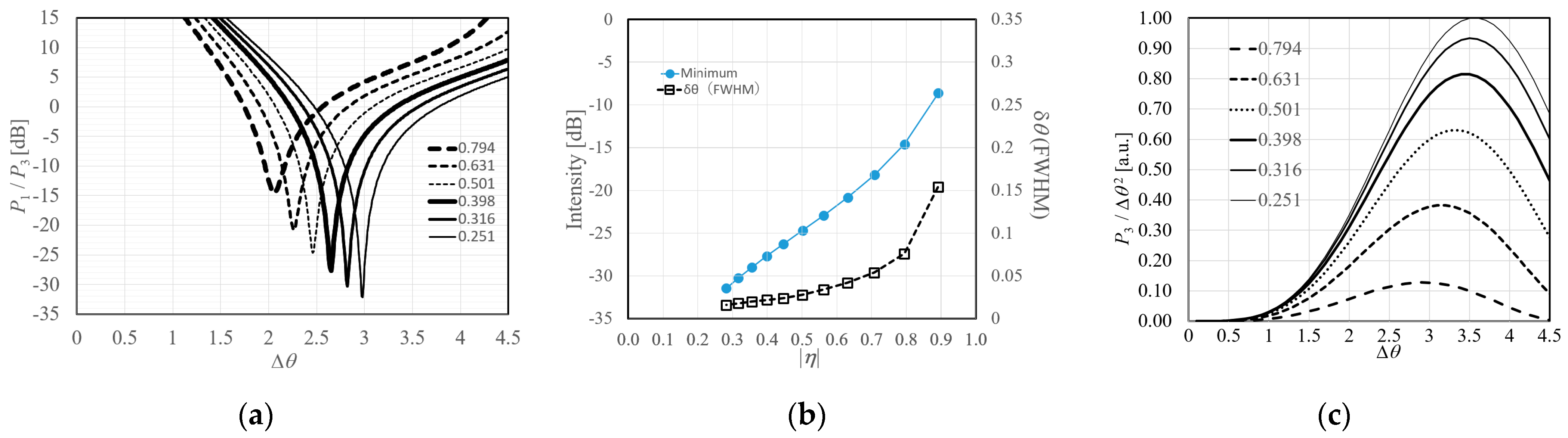
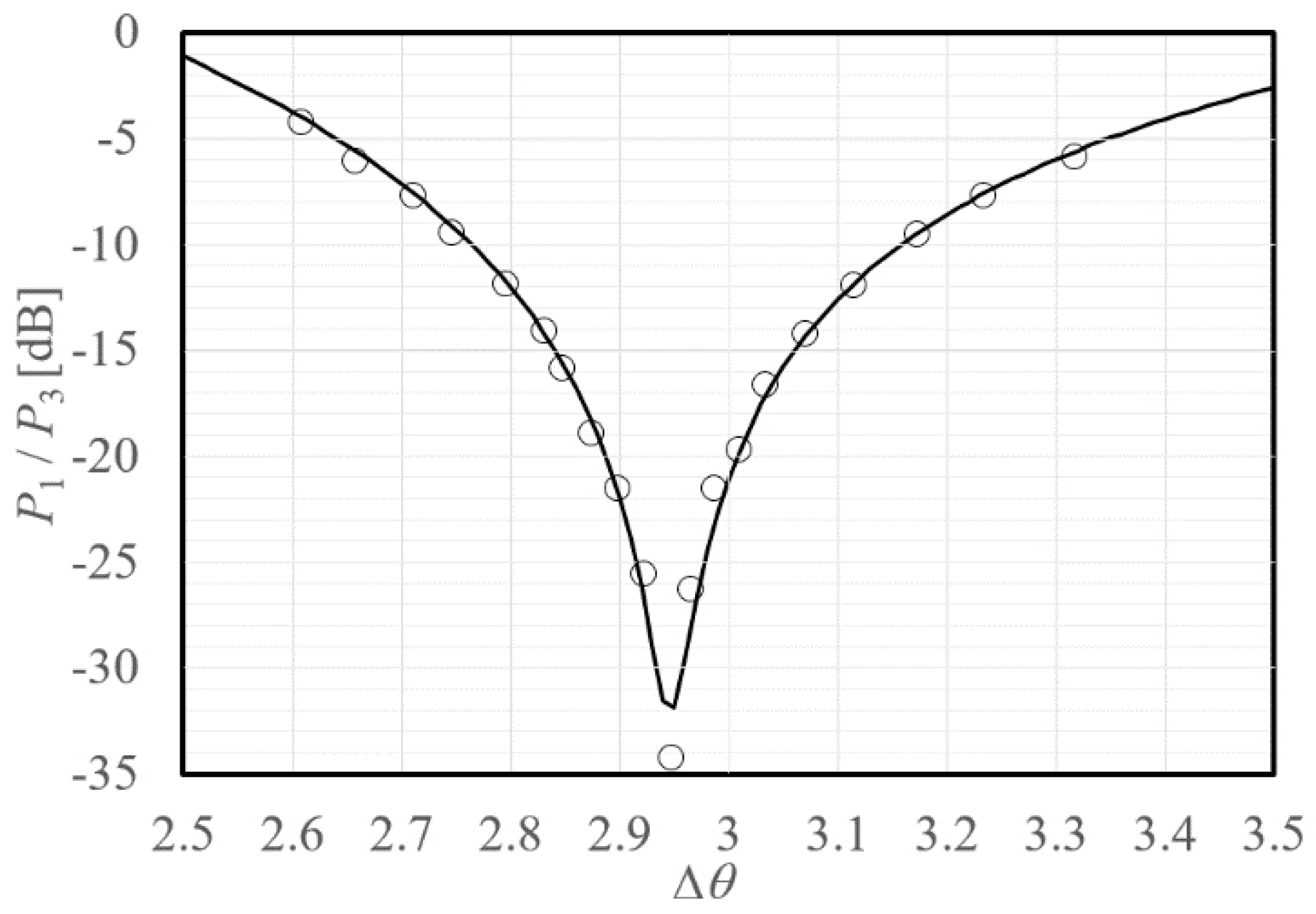
2.2. Suppression of First-Order Sideband for Third-Order Sideband Extraction

Eout is composed of many optical-frequency components when MZM is driven by strong sinusoidal RF signals. However, assuming that infinite ξ, Equations (5) and (7) imply that some optical-frequency components of Eout become zero under a certain condition. This fact can be derived by expanding the term TMZMθ, θB) + TMZM(ηΔθ, θB) using the m-th order Bessel function of the first kind Jm(x):
                        T MZM ( Δ θ ,   θ B ) + T MZM ( η Δ θ ,   θ B ) = + j m = [ J 2 m + 1 ( Δ θ ) + J 2 m + 1 ( η Δ θ ) ]   e j ( 2 m + 1 ) ω 0 t
Then, the (2m + 1)-th order optical sidebands disappear when the following equation is satisfied:
J 2 m + 1 ( Δ θ ) + J 2 m + 1 ( η Δ θ ) = 0 .
From the above equation, adequate parameters can be obtained for suppressing ±1st order optical sidebands (i.e., m = –1, 0) in the lightwave composed of –3rd~+3rd order optical sidebands. Note that, ideally, the null-biased MZM does not generate even-order optical sidebands. Although there are many solutions satisfying Equation (9), we focus on those with a negative η which can be achieved by a π-phase shift of the RF signal modulating clockwise lightwave [30,31]; i.e., η is in the range from –1 to 0. Additionally, η = –1 is not suitable, because Equation (9) is satisfied for arbitrary Δθ and m, meaning that all sidebands disappear. Figure 2a shows the plot of J1(x) versus x to find a numerical solution of Equation (9), and the pairs of the solution are shown in Figure 2b.
Adapting the parameter setting, the polarization of input (α = 45°) and output lightwaves can be drawn as Figure 3. While polarization of the lightwave launching into the PMSI is parallel to the axis of the polarizer (Figure 3a), ±1st-order optical sidebands of ECW (originating from the P-polarization incident lightwave) are flipped in their phase at a weak optical modulation while those of ECCW retains their phase. Then, as shown in Figure 3b, the polarization of ±1st-order optical sidebands is perpendicular to the polarization axis of the polarizer. In contrast, ±3rd-order optical sidebands are sufficiently small for the S-polarization components due to the modulation index including a small |η|; hence, only the sidebands of the P-polarization are projected by the polarizer so that they become the desired output lightwave, as shown in Figure 3c. Under a negative η, the intensity of the desired ±3rd-order optical sidebands, P3, is approximately expressed as
P 3 E 0 2 sin 2 2 α 4 [ J 3 ( Δ θ ) J 3 ( | η | Δ θ ) ] 2 ,
when the components perpendicular to the axis of the polarizer are neglected. For the ±1st-order optical sidebands, which are undesired components in the generated OTT signals, P1 is
P 1 E 0 2 [ sin 2 2 α 4 [ J 1 ( Δ θ ) J 1 ( | η | Δ θ ) ] 2 + ( cos 2 α J 1 ( Δ θ ) + sin 2 α J 1 ( | η | Δ θ ) ξ ) 2 ] .
From Equations (10) and (11), the optimum value of α is expected to be 45°. Figure 4a shows the dependence of P1/P3 on Δθ for several |η|, assuming that ξ = 104 (40 dB). The Δθ, giving the bottom of each dip, corresponds to the solution of Equation (9). With a decreasing |η| (i.e., an increase in attenuation), the dip of each plot gradually shifts to the higher Δθ. Additionally, the dip becomes narrower with a decrease in |η|, originating from the fact that the slope of J1(x) increases when the argument x is far from x0 = 1.841, which gives a local maximum of J1(x0). This fact is also summarized in Figure 4b, which show dependence of the maximum suppression ratio of the 1st-order optical sidebands and 3 dB width of the dips versus |η|. This means that, by adopting a lower |η| (higher attenuation), the suppression ratio is enhanced by more than 30 dB, while the suppression ratio is degraded by deviations of η and Δθ. A deviation in α has less of an effect on the suppression ratio given a sufficiently high polarization extinction ratio, while the deviation directly affects P3 and P1, as implied by Equations (10) and (11).
Regarding the desired optical signal power P3, the output power is increased with increase of Δθ, according to the characteristic of J3(x). For focusing on conversion efficiency from the input RF drive signal power, P3 normalized by Δθ2 is plotted on Figure 4c for several |η|. As can be seen, P3θ2 is increased with a decreasing |η| and the Δθ giving the local maxima of each plot are gradually increased, in the range of 3–3.5 in Δθ.

3. Experiments

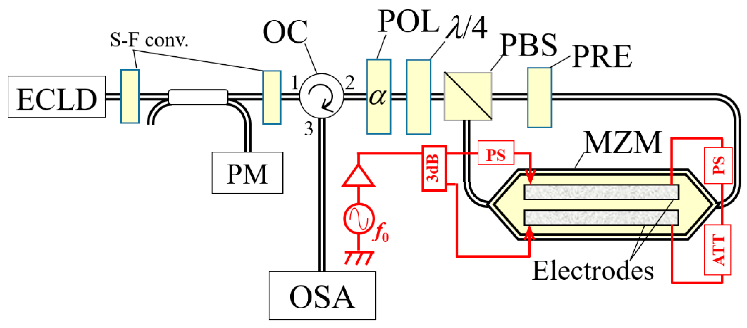
3.1. Experimental Setup and Proof-of-Concept Experiment

For conducting an experiment, we evaluate the wavelength dependence of the extinction ratio (ER) of the MZM integrated into a Z-cut Lithium Niobate substrate [31]. Halfwave voltage and modulation bandwidth of the modulation electrodes were evaluated to be 2.4 V and 23 GHz respectively, for each arm. The ER was designed to be more than 20 dB, and the insertion loss was evaluated to be 5.7 dB, at a wavelength of 1550 nm. To evaluate the wavelength dependence of ER, optical-power transmission spectra of MZM were obtained using a wavelength-swept light source (Agilent, 81689A) with a line-width of around 1 MHz. Transmission spectra of MZM were measured under each of its null- and in-phase conditions at a wavelength of 1550 nm, and the condition was fixed during each of the spectrum measurements. For wavelengths ranging from 1530 nm to 1570 nm, ERs of more than 30 dB were obtained from the MZM. And, at the wavelength of 1550 nm, ER was evaluated to be more than 40 dB. Then, the suppression of undesired even-order sidebands and carriers is sufficiently guaranteed due to destructive interference within MZM.
Figure 5 shows the experimental setup for evaluating the wavelength tunability of the OTT signal generator [30,31]. For the lightsource of the OTT signal generator, we employed an external-cavity laser diode (Agilent, 81689A). By using a 2 × 2 optical coupler followed by a polarization-maintaining optical circulator (OC), a polarizer (polarization extinction ratio >35 dB) and a quarter-waveplate, the incident lightwave generated from the lightsource was introduced into PMSI, which was composed of a polarizing beam splitter (polarization extinction ratio >21 dB, insertion loss <1.0 dB), PRE and MZM. To compensate for the wavelength-dependence of polarization-mode dispersion of polarization-maintaining optical fibers (PMFs), some PMFs were connected to couple its slow- (fast-) axis to the fast- (slow-) axis of the other PMFs. In addition, a quarter waveplate was employed to rotate the polarization of parasitic unmodulated lightwaves originating from the reflection at the end of a PMF and/or PBS; hence, the parasitic unmodulated lightwaves were rejected by the polarizer. Among the setup, the components with a narrow wavelength range were the OC (1550 ± 30 nm) and the 2 × 2 optical coupler (1550 ± 20 nm), which restricts the tunable range of the setup. However, the latter was used just for monitoring the launched optical power, so that it can be removed from the setup. The bias voltage of the MZM was adjusted to its null-bias condition at the wavelength of 1550 nm to suppress the optical carrier and even-order optical sidebands using the MZM. During measurement, the bias voltages were fixed. To drive the MZM, a 10 GHz RF signal was amplified (Ciao Wireless, CA-910-4042) and applied to the MZM. The applied RF power was evaluated using a conventional RF power meter (HP, 437B and 8481A). Using an optical spectrum analyzer, the optical spectrum of the lightwave emitted from the OTT signal generator was evaluated.

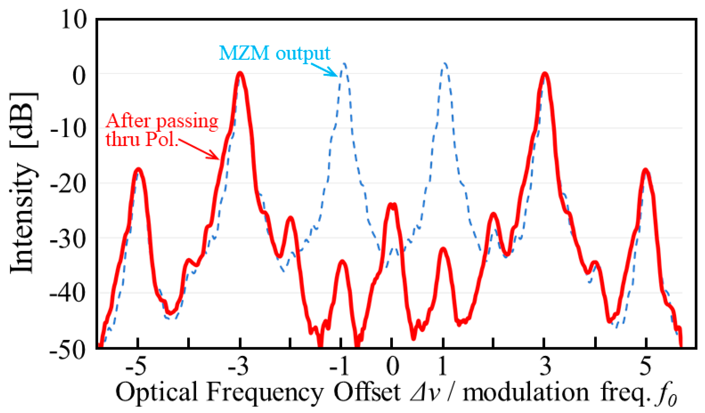
3.2. Experimental Results Obtained from 1550 nm Seed Lightwave

Figure 6 shows the typical optical spectra of the experimentally obtained OTT signals and the strongly modulated lightwave launching into PBS. The RF signal amplitude was adjusted to set the modulation index Δθ to 2.93, and the RF attenuation 1/|η| required for selective polarization rotation was adjusted to 11 dB, i.e., two modulation indices Δθ and |ηθ (=0.83) were obtained from the single MZM. As can be seen, the ±1st-order optical sidebands were suppressed by 34 dB by the polarizer, and the desired ±3rd-order optical sidebands were −28 dBm to −29 dBm. Although no feedback system was adopted in the experimental setup simply placed in a room without strict thermal shielding, the obtained optical output power was sufficiently stable; power fluctuation of the suppressed ±1st-order optical sidebands was within ±0.3 dB for 8 h. This implies that the phase difference between the lightwaves circulating in PMSI does not fluctuate due to the use of the same one polarization mode of PMSI. Using both polarization modes in the PMSI composed of PMFs, unavoidable fluctuation in optical-phase difference would be induced by temperature fluctuation. It should be noted that only the ±1st-order optical sidebands to be suppressed at the polarizer are involved in the effect of the phase-difference fluctuation, while the other sidebands and carrier do not suffer from such an effect: although intensity fluctuation of even-order ones including the carrier might originate from that of MZM bias, and its degree is sufficiently small. Additionally, the other odd-order (in this case ±3rd- and ±5th-order) ones do not undergo interference so that their intensity is also stable.
To evaluate the suppression of ± 1st-order optical sidebands, we experimentally evaluate the dependence of the intensity on the induced optical phase Δθ under the fixed η, as shown in Figure 7. As can be seen, the intensity plots agree well with the analytically obtained dip characteristic for RF attenuation 1/|η| = 11.5 dB, supporting the validity of the model analysis shown in Figure 4a of Section 2.2. The 0.5-dB difference against the RF attenuation in the setup (11 dB) may be due to the accumulation of the other insertion losses such as DC blocks and bias tees, and the residual calibration error of the RF power meter. The experimentally obtained intensity was −35 dB, which was restricted by the lower limit of the optical spectrum analyzer used in the experiment and the ER of the polarizer. The degree of the suppressed intensity is also evaluated under the condition of satisfying Equation (9) for the negative η, which is shown in Figure 8. With a decrease in Δθ, the intensity gradually decreased and followed the analytical result. Some deviation in the experimental results would be mainly due to the deviations of RF power and RF attenuator, besides instrument accuracy of the optical spectrum analyzer.
Figure 9 shows RF spurs against Δθ obtained from a photodiode (PD) with a 3 dB bandwidth of 70 GHz (Finisar, XPDV3120R) and an RF harmonic mixer (HP, 11970U) connected to an RF spectrum analyzer (HP, 8563E). First- (10 GHz) and fourth-order (40 GHz) spurs were detected with the degree of ~−30 dB, mainly originating from the beat of the desired components, their neighbor components (±2nd-order components), and the ±1st-order components cut by the polarizer. In contrast, second-order (20 GHz) spurs were relatively strong: around −10 dB against the desired lightwave components. These spurs are due to the desired components and the ±5th-order components. Additionally, these spurs were stronger than the expected power. Such a difference might be ascribed to the effect of dispersion of optical fibers. However, the strength of these spurs might not be significant: these RF frequencies are sufficiently far from the desired sextupled signal frequency so that they can be rejected by RF signal processing such as using an RF band-pass filter [29].

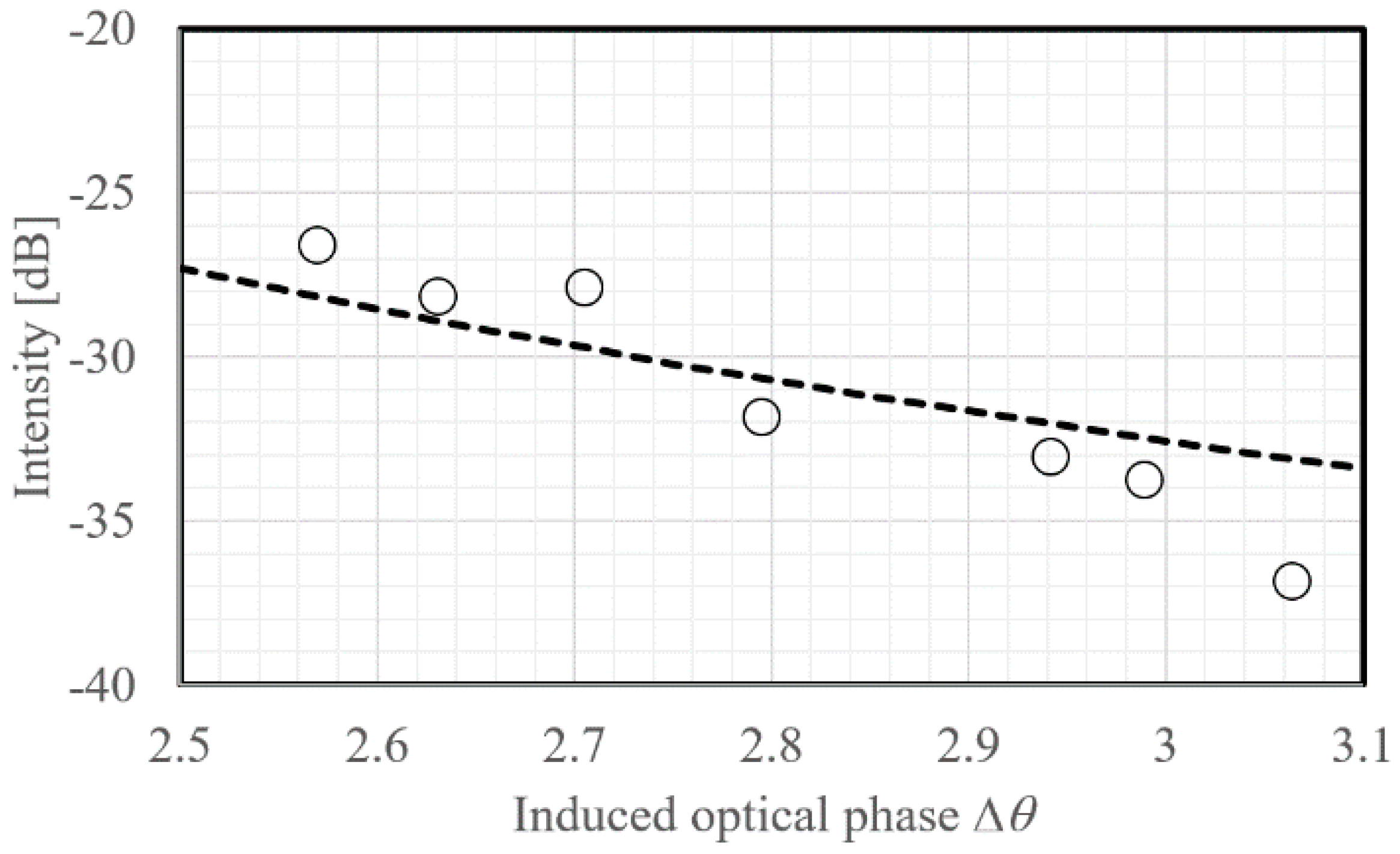
3.3. Wavelength-Tunable OTT Signal Generation

Figure 10 shows the typical optical spectra of OTT signals obtained from the generator with several seed lightwave wavelengths. The OTT signals were successfully generated without increasing the spurs: for the intensity ratio of ±1st-order optical sidebands against the desired ±3rd-order ones, more than 20 dB was achieved over a 40 nm wavelength range in the C-band, owing to the wavelength-independent ER of the MZM and the sufficiently high polarization extinction ratio of the polarizer in the broad-bandwidth range. In acquisition of Figure 10, the bias voltage of MZM was fixed at its null point for the wavelength of 1550 nm, to avoid a complicated adjustment of the bias voltage. Such a constant voltage might also induces residual spurs due to a slight deviation in the bias voltage condition from the null, when the wavelength of the seed lightwave shifts from 1550 nm. The suppression ratio would be further enhanced if we accept bias voltage tracking according to the wavelength of the seed lightwave. Power fluctuations of the desired OTT signals due to the seed-wavelength changes were within −25~−32 dBm.

4. Summary

We demonstrated an optical two-tone signal generation scheme at arbitrary wavelengths without involving complicated optical signal processing in the wavelength axis. Using an analytical approach, we optimized the driving condition for suppressing undesired lightwave components and conducted a proof-of-principle experiment. Due to the sufficiently high ER of the MZM and polarizer, the ±1st-order optical sidebands has been suppressed with a ratio of more than 20 dB against the desired wavelength components. Because this scheme requires no optical filters, it can be useful for generating optical two-tone signals at arbitrary wavelengths and may be extended to RF signal measurement by combining other microwave-photonics techniques.

Author Contributions

Conceptualization, A.C.; methodology, A.C.; software, Y.A. and A.C.; validation, A.C. and Y.A.; formal analysis, A.C. and Y.A.; investigation, Y.A. and A.C.; resources, A.C.; data curation, Y.A. and A.C.; writing—original draft preparation, A.C.; writing—review and editing, A.C. and Y.A.; visualization, A.C. and Y.A.; supervision, A.C.; project administration, A.C.; funding acquisition, A.C. All authors have read and agreed to the published version of the manuscript.

Funding

This work was supported in part by Japan Society for the Promotion of Science (20K21878, 20H02141) and the Telecommunications Advancement Foundation, Japan.

Institutional Review Board Statement

Not applicable.

Informed Consent Statement

Not applicable.

Data Availability Statement

Not applicable.

Acknowledgments

The authors would like to thank K. Higuma of Sumitomo Osaka Cement Co., Ltd. for supplying an MZM, and K. Takada, Y. Takahashi, and K. Miura for fruitful comments.

Conflicts of Interest

The authors declare no conflict of interest.

References

  1. Shih, P.-T.; Lin, C.-T.; Jiang, W.-J.; Chen, Y.-H.; Chen, J.; Chi, S. Full duplex 60-GHz RoF link employing tandem single sideband modulation scheme and high spectral efficiency modulation format. Opt. Express 2009, 17, 19501–19508. [Google Scholar] [CrossRef] [PubMed]
  2. Hirata, A.; Yamaguchi, R.; Kosugi, T.; Takahashi, H.; Murata, K.; Nagatsuma, T.; Kukutsu, N.; Kado, Y.; Iai, N.; Okabe, S.; et al. 10-Gbit/s Wireless Link Using InP HEMT MMICs for Generating 120-GHz-Band Millimeter-Wave Signal. IEEE Trans. Microw. Theory Tech. 2009, 57, 1102–1109. [Google Scholar] [CrossRef]
  3. Qi, G.; Yo, J.; Seregelyi, J.; Paquet, S.; Belisle, C. Generation and distribution of a wide-band continuously tunable millimeter-wave signal with an optical external modulation technique. IEEE Trans. Microw. Theory Tech. 2005, 53, 3090–3097. [Google Scholar]
  4. Kiuchi, H. Highly stable millimeter-wave signal distribution with an optical round-trip phase stabilizer. IEEE Trans. Microw. Theory Tech. 2008, 56, 1493–1500. [Google Scholar] [CrossRef]
  5. Ghelfi, P.; Laghezza, F.; Scotti, F.; Serafino, G.; Capria, A.; Pinna, S.; Onori, D.; Porzo, C.; Scaffardi, M.; Malacarne, A.; et al. A fully photonics-based coherent radar system. Nature 2014, 507, 341–345. [Google Scholar] [CrossRef] [PubMed]
  6. Nagatsuma, T.; Horiguchi, S.; Minamikata, Y.; Yoshimizu, Y.; Hisatake, S.; Kuwano, S.; Yoshimoto, N.; Terada, J.; Takahashi, H. Terahertz wireless communications based on photonics technologies. Opt. Express 2013, 21, 23736–23747. [Google Scholar] [CrossRef] [PubMed]
  7. Armor, J.B., Jr.; Robinson, S.R. Phase-lock control considerations for coherently combined lasers. Appl. Opt. 1979, 18, 3165–3175. [Google Scholar] [CrossRef] [PubMed]
  8. Simsek, A.; Arafin, S.; Kim, S.-K.; Morrison, G.B.; Johansson, L.A.; Mashanovitch, M.L.; Coldren, L.A.; Rodwell, M.J.W. Evolution of Chip-Scale Heterodyne Optical Phase-Locked Loops Toward Watt Level Power Consumption. IEEE/OSA J. Lightwave Technol. 2018, 36, 258–264. [Google Scholar] [CrossRef]
  9. O’Reilly, J.J.; Lane, P.M.; Heidemann, R.; Hofstetter, R. Optical generation of very narrow linewidth millimeter wave signals. Electron. Lett. 1992, 28, 2309–2310. [Google Scholar] [CrossRef]
  10. Izutsu, M.; Yanase, Y.; Sueta, T. Broadband traveling wave modulator using a LiNbO3 optical waveguide. IEEE J. Quantum Electron. 1977, QE-13, 287–290. [Google Scholar] [CrossRef]
  11. Izutsu, M.; Itoh, T.; Sueta, T. 10 GHz bandwidth traveling-wave LiNbO3 optical waveguide modulator. IEEE J. Sel. Top. Quantum Electron. 1978, QE-14, 394–395. [Google Scholar] [CrossRef]
  12. Mohamed, M.; Zhang, X.; Hraimel, B.; Wu, K. Analysis of frequency quadrupling using a single Mach-Zehnder modulator for millimeter-wave generation and distribution over fiber systems. Opt. Express 2008, 16, 10786–10802. [Google Scholar] [CrossRef] [PubMed]
  13. Kawanishi, T.; Sasaki, M.; Shimotsu, S.; Oikawa, S.; Izutsu, M. Reciprocating optical modulation for harmonic generation. IEEE Photon. Technol. Lett. 2001, 13, 854–856. [Google Scholar] [CrossRef]
  14. Pan, Z.; Chandel, S.; Yu, C. 160 GHz optical pulse generation using a 40 GHz phase modulator and two stages of delayed MZ interferometers. In Proceedings of the Technical Digest of Conference on Lasers and Electro-Optics and 2006 Quantum Electronics and Laser Science Conference 2006 (CD), Long Beach, CA, USA, 21–26 May 2006; Optical Society of America: Washington, DC, USA, 2006. Paper CFP2. pp. 1–2. [Google Scholar]
  15. Izutsu, M.; Shikama, S.; Sueta, T. Integrated Optical SSB Modulator/Frequency Shifter. IEEE J. Quantum Electron. 1981, QE-17, 2225–2227. [Google Scholar] [CrossRef]
  16. Shimotsu, S.; Oikawa, S.; Saitou, T.; Mitsugi, M.; Kurodera, K.; Kawanishi, T.; Izutsu, M. Single side-band modulation performance of a LiNbO3 integrated modulator consisting of four-phase modulator waveguides. IEEE Photon. Technol. Lett. 2001, 13, 364–366. [Google Scholar] [CrossRef]
  17. Kawanishi, T.; Sakamoto, T.; Tsuchiya, M.; Izutsu, M. High Carrier Suppression Double Sideband Modulation Using an Integrated LiNbO3 Optical Modulator. In Proceedings of the 2005 International Topical Meeting on Microwave Photonics, Seoul, Korea, 14 October 2005; IEEE: Piscataway, NJ, USA, 2005; pp. 29–32. [Google Scholar]
  18. Lin, C.-T.; Shih, P.-T.; Chen, J.; Jiang, W.-J.; Dai, S.-P.; Peng, P.-C.; Ho, Y.-L.; Chi, S. Optical millimeter-wave up-conversion employing frequency quadrupling without optical filtering. IEEE Trans. Microw. Theory Tech. 2009, 57, 2084–2092. [Google Scholar]
  19. Lin, C.-T.; Shih, P.-T.; Jiang, W.-J.; Chen, J.J.; Peng, P.-C.; Chi, S. A continuously tunable and filterless optical millimeter-wave generation via frequency octupling. Opt. Express 2009, 17, 19749–19756. [Google Scholar] [PubMed]
  20. Shi, P.; Yu, S.; Li, Z.; Song, J.; Shen, J.; Qiao, Y.; Gu, W. A novel frequency sextupling scheme for optical mm-wave generation utilizing an integrated dual-parallel Mach-Zehnder modulator. Opt. Commun. 2010, 283, 3667–3672. [Google Scholar] [CrossRef]
  21. Lu, G.W.; Sakamoto, T.; Chiba, A.; Kawanishi, T.; Miyazaki, T.; Higuma, K.; Ichikawa, J. Optical minimum-shift-keying transmitter based on a monolithically integrated quad Mach–Zehnder in-phase and quadrature modulator. Opt. Lett. 2009, 34, 2144–2146. [Google Scholar] [CrossRef]
  22. Kaneko, A.; Yamazaki, H.; Yamada, T. Compact Integrated 100 Gb/s Optical Modulators Using Hybrid Assembly Technique with Silica-Based PLCs and LiNbO3 Devices. In Proceedings of the Optical Fiber Communication Conference and National Fiber Optic Engineers Conference, OSA Technical Digest (CD), San Diego, CA, USA, 22–26 March 2009; Optical Society of America: Washington, DC, USA, 2009. Paper OThN3. pp. 1–2. [Google Scholar]
  23. Chiba, A. Integrated optical modulation devices open the door for optical communication being close to the Shannon limit. Electron. Lett. 2010, 46, 186. [Google Scholar] [CrossRef]
  24. Chiba, A.; Sakamoto, T.; Kawanishi, T.; Higuma, K.; Sudo, M.; Ichikawa, J. 16-level quadrature amplitude modulation by monolithic quad-parallel Mach-Zehnder optical modulator. Electron. Lett. 2010, 46, 227–228. [Google Scholar] [CrossRef]
  25. Sakamoto, T.; Chiba, A. Coherent synthesis of optical multilevel signals by electrooptic digital-to-analog conversion using multiparallel modulator. J. Sel. Top. Quantum Electron. 2010, 16, 1140–1149. [Google Scholar] [CrossRef]
  26. Liu, W.; Wang, M.; Yao, J. Tunable Microwave and Sub-Terahertz Generation Based on Frequency Quadrupling Using a Single Polarization Modulator. IEEE/OSA J. Lightwave Technol. 2013, 31, 1636–1644. [Google Scholar]
  27. Wang, W.T.; Li, W.; Zhu, N.H. Frequency quadrupling optoelectronic oscillator using a single polarization modulator in a Sagnac loop. Opt. Commun. 2014, 318, 162–165. [Google Scholar] [CrossRef]
  28. Chiba, A.; Akamatsu, Y.; Takada, K. Optical two-tone signal generation without use of optical filter for photonics-assisted radio-frequency quadrupling. Opt. Lett. 2015, 40, 3651–3654. [Google Scholar] [CrossRef] [PubMed]
  29. Chiba, A.; Akamatsu, Y.; Takada, K. RF frequency sextupling via an optical two-tone signal generated from two modulation lightwaves from one Mach-Zehnder optical modulator. Opt. Express 2015, 23, 26259–26267. [Google Scholar] [CrossRef] [PubMed]
  30. Chiba, A.; Akamatsu, Y.; Takada, K. Long-term stable 60 GHz optical two-tone signal by destructive optical interference obtained from RF phase adjustment. Electron. Lett. 2016, 52, 736–737. [Google Scholar] [CrossRef]
  31. Chiba, A.; Akamatsu, Y.; Takada, K. Wavelength- independent optical two-tone signal generator composed of one single Mach-Zehnder optical modulator and a polarizer. In Proceedings of the 2016 IEEE Photonics Conference, Waikoloa, HI, USA, 2–6 October 2016; IEEE: Piscataway, NJ, USA, 2009; pp. 736–738. [Google Scholar]
Figure 1. Analysis model of wavelength-tunable optical two-tone signals generation based on an MZM in PMSI with PRE. PBS: polarizing beam splitter, PRE: polarization-rotation element, POL: polarizer. Blue solid arrows and red solid arrows depict the electric field (polarization) of lightwave propagating in the PMSI in the clockwise direction and the counter-clockwise direction, respectively. In the configuration, lightwaves propagate according to black open arrows. Dashed arrows indicate the RF signal modulating lightwave in the PMSI.
Photonics 09 00194 g001
Figure 2. (a) A solution of Equation (9) for m = 0 and Δθ = 2.485, and (b) the combination of η and Δθ satisfying Equation (9).
Photonics 09 00194 g002
Figure 3. Alignment of the polarization axis of the polarizer and polarization state of an (a) incident lightwave and the output lightwave composed of (b) ±1st-order optical sidebands and (c) ±3rd-order optical sidebands. Note that the propagation axis (Z) of (a) is opposite to that of (b,c), while the spatial coordinate is consistent.
Photonics 09 00194 g003
Figure 4. (a) Dependence of 1st-order optical sideband intensity on Δθ when η is in negative and its absolute value |η| equals to 0.794 (2 dB attenuation), 0.631 (4 dB attenuation), 0.501 (6 dB attenuation), 0.398 (8 dB attenuation), 0.316 (10 dB attenuation), 0.251 (12 dB attenuation). Polarization extinction ratio ξ is assumed to be 104. All plots are normalized by the intensity of ±3rd-order optical sidebands obtained from each η. (b) Minimum intensity and 3-dB width of the dips in (a) versus |η|, ranging from 1 dB to 11 dB with a step of 1 dB in RF attenuation 1/|η|. (c) Output power of desired wavelength component P3 normalized by Δθ2 being proportional to input RF power. Calculation is performed using Equation (10) and setting of |η| is common with (a). All traces are normalized by the maximum when |η| equals to 0.251.
Photonics 09 00194 g004
Figure 5. Experimental setup. Thin red lines are the RF signal connections, and double solid lines are connections for lightwave. ECLD: External-cavity diode laser, S-F conv.: PMF connector coupling a slow- (fast-) axis of the either PMF to a fast- (slow-) axis of the other, PM: optical power-meter, OC: Optical circulator, POL: Polarizer, λ/4: quarter-waveplate, PBS: Polarizing beam-splitter, PRE: Polarization-rotation element, MZM: Mach-Zehnder optical Modulator, OSA: optical spectrum analyzer, 3 dB: 3 dB RF hybrid coupler, PS: RF phase shifter, and ATT: Attenuator.
Photonics 09 00194 g005
Figure 6. Optical spectrum of 60-GHz separation OTT signal (Solid red line) composed of strongly modulated lightwave (Dashed blue line) and weakly modulated lightwave. The frequency of RF signal driving MZM, f0, is 10 GHz. Horizontal and vertical axes are normalized by f0 and the intensity of ±3rd-order sidebands, respectively.
Photonics 09 00194 g006
Figure 7. Intensity of ±1st-order optical sidebands obtained from the experiment (open circles) and analytical model when RF attenuation 1/|η| =11.5 dB (solid line), normalized by ±3rd-order optical sideband intensity.
Photonics 09 00194 g007
Figure 8. Intensity of ±1st-order optical sidebands normalized by ±3rd-order optical sideband intensity, obtained from the experiment (open circles) and analytical model where ER of the polarizer is 41.5 dB (dashed line). At each Δθ, η is set to satisfy Equation (9).
Photonics 09 00194 g008
Figure 9. Power ratio of spurs versus the induced optical phase Δθ. Origin of the vertical axis corresponds to 60-GHz RF power. Circles, triangles, and squares denote the 10 GHz (1st-order), 20 GHz (2nd-order), and 40 GHz (4th-order) RF signals. The filled symbols indicate experimental results, while the opened symbols indicate results from numerical calculations.
Photonics 09 00194 g009
Figure 10. Optical spectra of 60-GHz separation OTT signals generated from the setup where the bias voltages of the MZM were fixed at its null point for the wavelength of 1550 nm. Wavelengths of seed lightwave were adjusted to (a) 1530.06 nm, (b) 1540.05 nm, (c) 1550.05 nm, and (d) 1560.04 nm, respectively.
Photonics 09 00194 g010
Publisher’s Note: MDPI stays neutral with regard to jurisdictional claims in published maps and institutional affiliations.

