Article

Non-Mechanical Multiplexed Beam-Steering Elements Based on Double-Sided Liquid Crystal Metasurfaces

by
Maxim V. Gorkunov
1,2,*,
Artur R. Geivandov
1,
Alena V. Mamonova
1,
Ivan V. Simdyankin
1,
Irina V. Kasyanova
1,
Alexander A. Ezhov
1,3 and
Vladimir V. Artemov
1
1
Shubnikov Institute of Crystallography, Federal Scientific Research Centre “Crystallography and Photonics”, Russian Academy of Sciences, 119333 Moscow, Russia
2
National Research Nuclear University MEPhI (Moscow Engineering Physics Institute), 115409 Moscow, Russia
3
Faculty of Physics, Lomonosov Moscow State University, 119991 Moscow, Russia
*
Author to whom correspondence should be addressed.
Photonics 2022, 9(12), 986; https://doi.org/10.3390/photonics9120986
Submission received: 17 November 2022 / Revised: 2 December 2022 / Accepted: 9 December 2022 / Published: 15 December 2022
(This article belongs to the Special Issue Active/Reconfigurable Metasurfaces)

Abstract

:
We propose, optimize, fabricate and test beam-steering elements based on double-sided liquid-crystal (LC) metasurfaces allowing for diffractive and spectral multiplexing, and thus covering three different beam deflection directions each. While straightforward parallel design requires one diffractive beam-steering element per a direction determined by Bragg’s law, double-sided LC-metasurfaces are remarkably flexible and allow optimization for three operation modes at different applied voltages: zero-voltage mode with dominant +1 order red light and +2 order blue light diffraction; intermediate mode at 1.4–1.6 V voltage with dominant +1 order blue light diffraction; and transparent mode at 5 V voltage. We comprehensively study three such elements with 6, 8 and 10 micrometer periods and verify their capability of deflecting blue and red light beams with 40–70% efficiencies in nine target directions with 10 ms characteristic switching times.

Graphical Abstract

1. Introduction

The precise splitting and steering of light beams is a key functionality of optical elements for free-space telecommunications [1], 3D shape acquisition [2] and LiDARs [3]. Traditional LiDAR elements perform efficient light deflection with mechanically moving parts, which complicates the design, compromises the long term stability, and increases the size and weight. The necessity of non-mechanical analogs to redirect light by virtue of intrinsic reconfiguration is widely recognized [4] and numerous sophisticated devices enabled by the latest nanotechnology advances are being proposed [5]. Growing attention is attracted to beam-steering liquid crystal (LC) devices which are compact and conveniently controlled by low voltage [6,7,8]. The broad availability of LC materials and efficient production routes already established for the LC display industry promise fast commercial implementation.
As with many other LC devices, a beam steerer operates relying on the reorientation of an optically transparent anisotropic LC layer stimulated by relatively low voltage. In contrast to uniformly aligned display cells, beam deflectors impart non-uniform sawtooth-like phase profiles to the light wavefronts. Applying the phased array concept, one can independently address micrometer size areas of the LC layer via a complex system of transparent microelectrodes. Plugging them with variable periodicity provides remarkable flexibility to the deflection, as its angle can be varied in accordance with Bragg’s law. The efficiency remains sufficiently high as long as the period is large enough for the linear gradient phase profiles to be precisely induced by a large number of electrodes per period. However, inevitable cross-talk between adjacent electrodes and a substantial contribution from the regions of phase flyback drastically suppress the efficiency of multielectrode configurations as soon as their period is decreased to approach the deflection angles of fractions of a degree [9,10].
Real-life applications demand beam steering in much wider ranges of directions, and different angle-expanding devices multiplying the deflection angle by about 2 [11] and even by up to 5 [12] times are being proposed. To cover the range of tens of degrees, they still require input elements deflecting light by several degrees. For visible light, such an element has to modulate the wavefront with a periodicity of 10 μ m or less. Various designs of the corresponding light deflecting LC-systems proposed recently all rely on adding to LC cells short-scale periodic components such as polymer blazed gratings [13], arrays of resistive polymer electrodes distributing sawtooth-like modulated voltage profiles to the LC layer [14], or photopatterned planar alignment layers stabilizing periodic modulations of nematic [15] and cholesteric [16] LCs. For the periodicity thus fixed, the corresponding elements deflect light in the direction of a particular optimal diffraction order from the set determined by Bragg’s law. To cover the large number of deflection angles required, e.g., for LiDAR applications, one can either stack many such elements to employ them in series [17] or create their large arrays operating in parallel. In both cases, the size and complexity of the whole device are drastically increased.
Here, we propose and realize the idea of spectral and diffractive multiplexed beam-steering LC elements in order to substantially reduce their number, avoiding sophisticated electrode systems and retaining conventional flat display-like LC-cell geometry. The practical realization is empowered by the recently developed concept of LC-metasurfaces relying on versatile LC microstructures stabilized upon patterned polymer alignment layers inducing submicrometer-scale modulations of the adjacent nematic LC director [18,19,20,21,22,23]. Lately, we have developed a precise method of creating such alignment layers by patterning rubbed polyimide films with a focused ion beam (FIB) [18,21]. While efficient beam deflection of blue light can be achieved using one such layer accompanied by a uniformly aligning opposite substrate [20], extending the spectral range onto the whole visible range is possible using a double-sided design with complementary alignment layers patterned on both substrates [23].
Now we further extend the double-sided design to create multiplexed beam-steering LC metasurfaces specifically optimized for efficient performance in three operating modes: +1 order diffraction of red light and +2 order diffraction of blue light; +1 order diffraction of blue light; and full transparency. The main advantages of such multiplexing as well as the corresponding optimization of LC-metasurfaces are recounted in Section 2. Based on the extensive numerical optimization of LC alignment patterns on both substrates for three different metasurface periods of 6, 8 and 10 μ m, we imprint them with FIB, assemble LC-cells and characterize their optical performance including the diffraction efficiency and electro-optical switching dynamics measurements as recounted in Section 3. We obtain the key functional parameters which are quantitatively in line with the theoretical expectations and, as discussed in Section 4, conclude that the LC-metasurfaces can be readily employed in versatile beam deflecting devices.

2. Main Idea, Design and Optimization

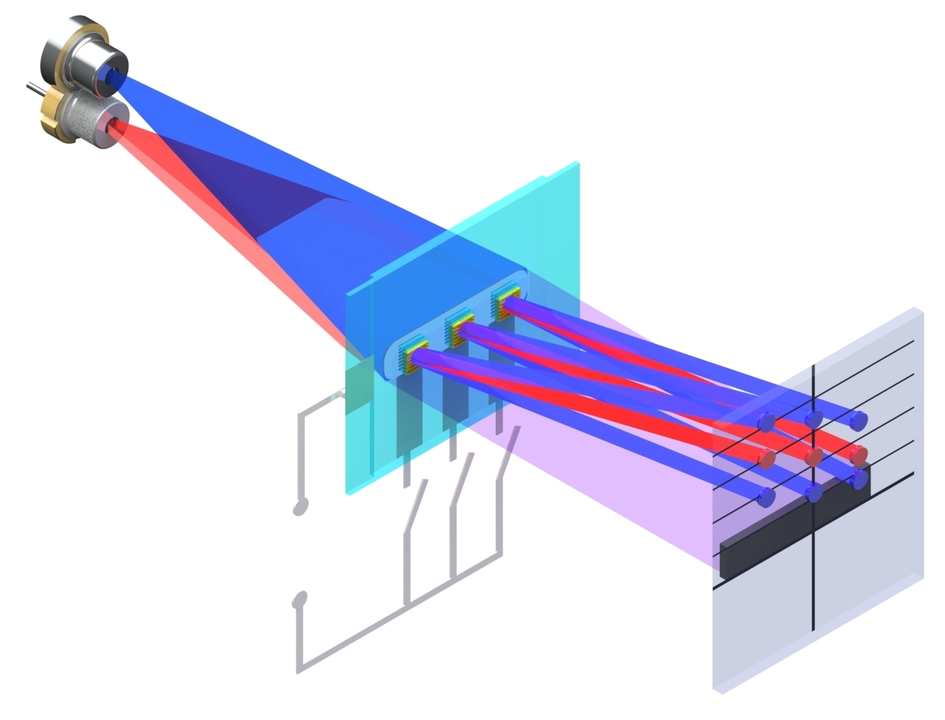
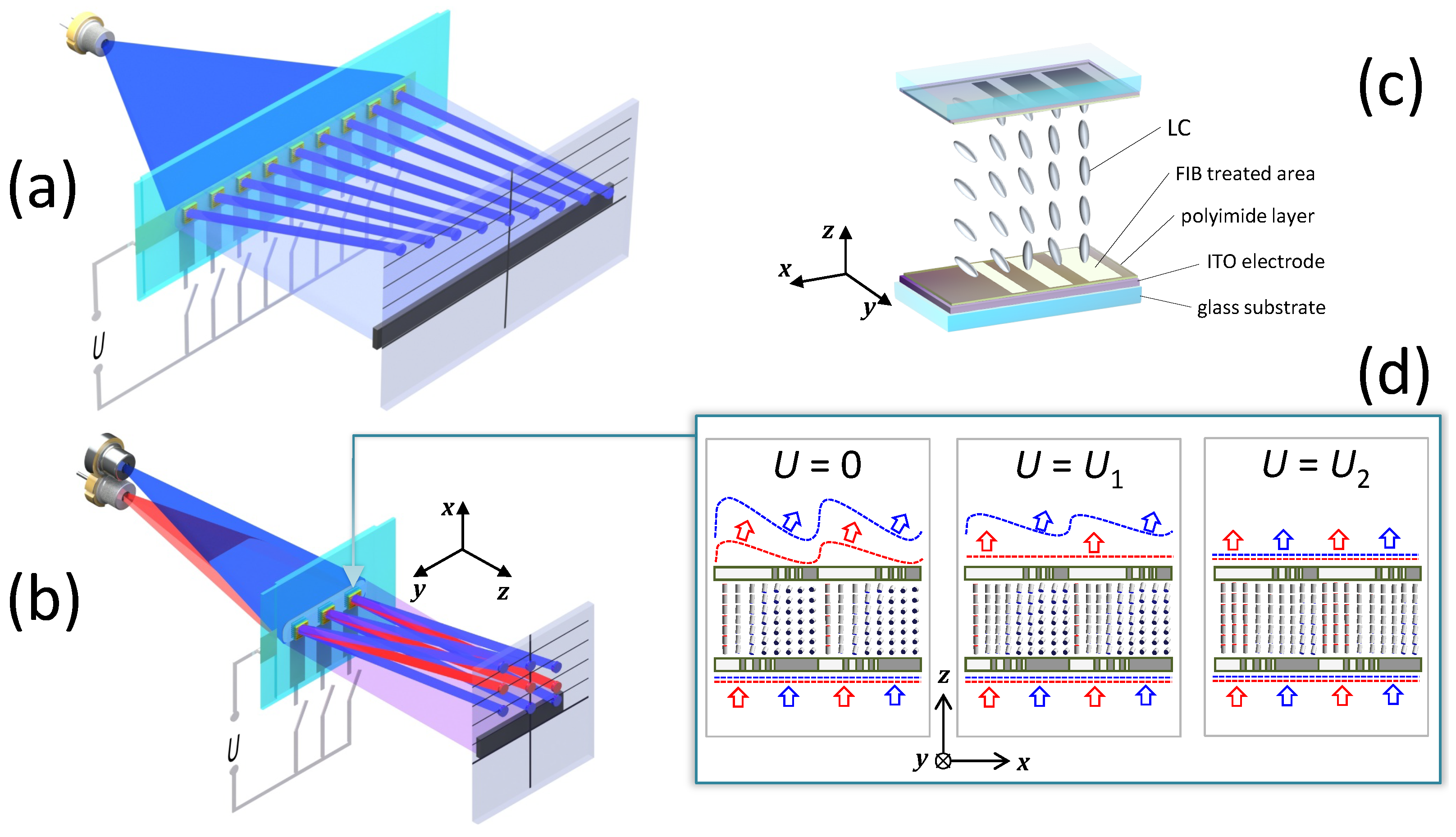
2.1. Advantages of Spectral and Diffractive Multiplexing

The function of a beam-steering device is to precisely send sequences of light beams in many different directions. The main challenge for non-mechanical realization is to cover many substantially different directions using reliable intrinsic reconfigurability which, as a rule, is based on subtle physical phenomena affecting the light beams in a perturbative manner. Various LC devices extensively developed in the past years are capable of efficient light deflection at a fixed angle of 5–10 , i.e., they essentially perform as switchable small-angle blazed gratings [13,14,15,16]. The deflection occurs as a result of diffraction into a particular dominant n-th order at an angle α n dictated by Bragg’s law:
sin α n = n λ P ,
where P is the grating period and λ is the light wavelength. Quantitatively, the performance is characterized by efficiency η n of the corresponding diffraction order, defined as the relative part of the incident light energy deflected at the angle α n . For the zeroth order, it coincides with the forward transmittance, η 0 = T .
To cover a large number of deflection angles, one has to fabricate the same number of steering elements, each optimized for a particular angle, and to combine them in parallel. For the sake of argument, in Figure 1a we present a sketch of exemplary device covering nine different deflection angles by nine switchable blazed gratings which can be based on anomalously refracting LC-metasurfaces [20]. Each element either efficiently deflects light at a particular angle dictated by Equation (1), or, when the voltage is applied, transmits it directly into the blocking cap. In this way, by illuminating the array of elements and selectively applying the voltage to them, one can send the light beams in an arbitrary subset of nine directions.
Our goal is to design multiplexed LC beam-steering elements to substitute the array in Figure 1a with a much more compact one covering the same number of different directions in space as shown in Figure 1b. This can be achieved by extending the set of available angles determined by Equation (1) by combining diffractive multiplexing (deflecting light into different orders of diffraction n) with spectral multiplexing (efficient diffraction of light of substantially different wavelengths λ ). Such specific functionality is rather non-trivial and, for example, it is beyond the capabilities of single-sided LC-metasurfaces efficiently diffracting the light in a narrow spectral range into +1 diffraction order [20]. Recently proposed double-sided LC-metasurfaces [23] offer a unique possibility of the practical realization of multiplexing: on the one hand, they efficiently deflect light of the whole visible spectrum, while, on the other hand, as we show below, they allow optimization for efficient diffraction into a higher +2 order.
Double-sided LC-metasurfaces self-assemble within a few micrometers gap between a pair of polymer alignment layers held by glass substrates with transparent indium tin oxide (ITO) electrode interlayers used for applying electric voltage to drive the switching, see Figure 1c. Qualitatively, the physical principle of multiplexed double-sided LC-metasurface operation is depicted in Figure 1d. Both substrates contain periodic patterns of stripes aligning the adjacent LC either vertically along the z-axis (at the areas processed by FIB) or in-plane along the y-axis normal to the drawing (at pristine rubbed polyimide areas). Combining stripes of different widths allows the induction of gradual reorientation of the LC director near the substrates, which is translated into the LC bulk by the orientational elasticity. As a result, linearly y-polarized incident light experiences non-uniform phase delay when passing through such an LC cell, and its wavefront is periodically modulated at the output. For efficient deflection, the wavefront has to approach a sawtooth shape with smooth linear gradient areas interrupted by sharp flyback areas, where the light phase folds by multiples of 2 π . Efficient +1 order diffraction occurs for folding by 2 π , while +2 order diffraction requires folding by 4 π , etc.
For multiplexed performance, a metasurface should operate in three modes with the diffraction efficiency maximized for the corresponding orders at zero voltage and at an intermediate low voltage. For the spectral multiplexing, we choose the target wavelengths of blue (450 nm) and red (630 nm) lasers. As shown in Figure 1c, in the zero-voltage mode U = 0 , a 4 π folding occurs for blue light and a nearly 2 π folding is established for red light, as its wavelength is considerably larger. Accordingly, efficient +2 order diffraction of blue light and +1 order diffraction of red light occurs. Applying intermediate voltage U 1 to flat solid LC-cell electrodes partially straightens the LC director field, decreasing the amplitude of refractive index modulation. Now, a 2 π folding is established for blue light which diffracts into +1 order, while the red light deflection is attenuated. For a higher applied voltage U 2 , the refractive index modulations are fully suppressed, and both red and blue light beams pass through the element directly.

2.2. Optimization of Multiplexed Elements

To reveal optimal alignment patterns, i.e., particular numbers and widths of alignment stripes for metasurfaces of different periods, we performed extensive numerical simulations using the finite element method in COMSOL Multiphysics. Equilibrium states of deformed nematic LC were obtained by numerically solving the corresponding continuous problem [24] using Weak Form PDE and taking the elastic coefficients of E7 nematic mixture used in further experiments known from the literature [25]: K 11 = 11.1 pN, K 22 = 6.5 pN and K 33 = 17.1 pN. The LC cell gap was set to 4 μ m as in our previous experiments [23]. On one hand, such a gap allows the accumulation of sufficient phase modulation, as light propagates through moderately optically anisotropic LC. On the other hand, it supports reasonably fast switching by low voltage. Note that the required voltage amplitude grows linearly and the switching time grows quadratically with the gap [24].
According to Equation (1), deflecting visible light by several degrees requires a metasurface period of 10 μ m or smaller. For the LC modulations not to become critically smoothed by the orientational elasticity, contrariwise, one has to keep the period larger than the LC-cell gap of 4 μ m. As a reasonable compromise, we chose to optimize metasurfaces of three different periods of 6, 8 and 10 μ m.
The LC orientation is parameterized by the polar angle θ measured from the vertical z-axis, while the azimuth angle remains constant, as the LC director alters between the y and z directions. Similarly to our previous works, we assumed rigid LC anchoring at all stripes and applied the Dirichlet boundary conditions θ = 0 on the FIB-processed stripes and θ = π / 2 on the stripes of pristine polyimide. Simulations were performed within a 2D domain containing one metasurface period with periodic boundary conditions set on its sides.
To account for the aligning effect of voltage applied across the LC layer, we introduced the standard dielectric term to the LC free energy density describing the energy of anisotropic LC locally subjected to electric field. The latter is self-consistently obtained by solving the Poisson equation for electric potential in anisotropic LC, assuming a fixed voltage drop between the substrates. Static (low-frequency) relative dielectric permittivity of the LC corresponds to the properties of the experimentally used E7 mixture: ε = 5.2 and ε | | = 19 .
The obtained equilibrium configurations were employed to evaluate the optical characteristics by solving the Maxwell equations using the Electromagnetic Waves Frequency Domain (EWFD) module of COMSOL Multiphysics and taking into account the actual LC cell structure including glass substrates and 150 nm thick transparent ITO electrodes with all material properties adopted from independent experimental data: the ITO refractive index as in the COMSOL material library [26] and the principal E7 nematic permittivity values set in terms of the Lorentzian model, fitting the experimental dispersion [27]. For consistence with experiments, the calculated transmittance and diffraction efficiencies were normalized by the forward transmittance of a homogeneous LC cell area.
LC metasurface optimization was performed considering the x-coordinates of the edges of FIB-processed aligning stripes as variables. For the objective functions, we took the value of +2 order diffraction efficiency at a wavelength of 450 nm and the value of +1 order diffraction efficiency at the same wavelength at an intermediate voltage of 1.5 V applied. The optimization was performed using the Nelder–Mead method with the sum of two objective functions maximized. To evaluate them at each optimization step, two weak-form LC elastic problems are solved for zero and intermediate voltages applied, as well as two corresponding optical transmission problems.
In this way, we optimize double-sided metasurfaces of three periods of 6, 8 and 10 μ m. The obtained optimal parameters of stripe patterns are given in Table 1. To illustrate the performance in three modes, in Figure 2a we present the spectra of relevant diffraction efficiencies η 1 , 2 and transmittance T of the optimized 10 μ m periodic metasurface. One can see that the efficiency of +1 order diffraction at the target red and blue wavelengths approaches remarkably high 80% values at the zero and intermediate 1.5 V voltages, respectively. Moreover, +2 diffraction efficiency can reach almost 60% at the zero voltage and it fully vanishes at low intermediate voltage. Applying 5 V is enough to establish a transparent state with negligible diffraction. Note that these efficiencies are evaluated by accounting for all internal reflections within the multilayer LC cell (see Figure 1a), including, for instance, the reflections from ITO interlayers, which attenuate the forward transmittance by 10–15% in the blue range, even when the diffraction is suppressed by higher voltage.
The underlying physics can be understood from the corresponding colormaps of the LC-director polar angle in Figure 2b. One can see that the orientational LC elasticity prevents abrupt discontinuities of the director field in the LC bulk presumed by the simplified picture of LC orientation shown in Figure 1d. Apart from this, the modeling generally confirms the expected LC behavior in different modes. In the zero-voltage mode, the LC director gradually realigns from a practically vertical orientation on the left (blue color) to the almost planar orientation on the right (red color), thus producing the strongest possible difference of the transmitted light phases. In the intermediate voltage mode, the orientation on the left remains fully vertical, while the bulk of the LC cell on the right partially realigns also vertically reducing the resulting phase difference. At a higher voltage, the LC-director is nearly perfectly aligned along the vertical direction, and the uniform LC-cell is almost transparent.

3. Experimental Multiplexed Elements

3.1. Fabrication

To implement the designed elements, we employed the preparation and FIB patterning technique developed in our recent works [18,19,20,21,22,23]. The substrates were based on standard soda-lime display-quality glass plates covered with 150 nm thick transparent ITO electrodes. Planar alignment polymer layers were produced by spin coating of a 1% solution of polyamic acid in dimethylformamide, annealing at 250 C for 1 h and unidirectional rubbing with a soft cotton cloth. FIB-patterning of rubbed polyimide layers was performed using an FEI Scios DualBeam electron microscope controlled by digital raster templates. The microscope magnification was set to ensure that a single raster pixel corresponded to a 0.1 × 0.1 μ m 2 area of the substrate surface. The patterns consisting of 3500 × 3500 px 2 were imprinted as 350 μ m large squares by irradiating corresponding pixels for 150 μ s with a 0.1 nA beam of Ga + ions accelerated to 30 keV.
Stacking and assembling the patterned substrates in an LC-cell was performed with 4 μ m Sekisui Micropearl plastic spacers securing the cell gap. After the gap was filled with E7 (Merck) nematic LC, fine relative substrate adjustment was performed using a custom made device [28] comprising two 3D-printed plastic frames equipped with Newport Vernier Micrometer SM-13 screws. The quality of LC-alignment was monitored by polarizing optical microscopy (POM) using Olympus CX31PF-5 and BX53MTRF microscopes. For finer substrate adjustment, back focal plane (BFP) images of the metasurfaces were monitored as indicators of their proper self-assembly manifested by strong red and blue light diffraction at zero voltage. In particular, to maximize the visibility of +2 diffraction order, BFP images upon blue light illumination through a violet color glass filter VG1 [29] were monitored.

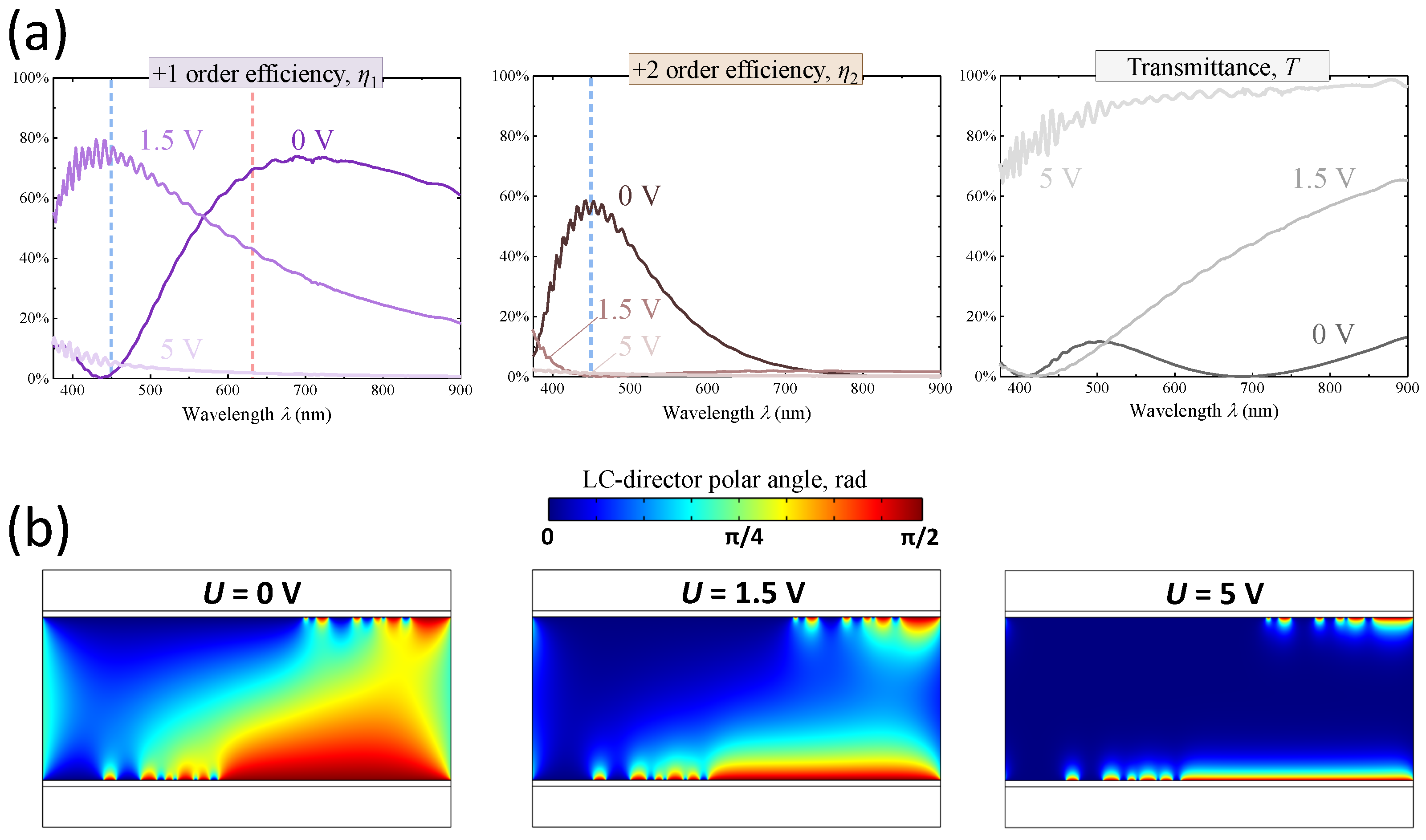
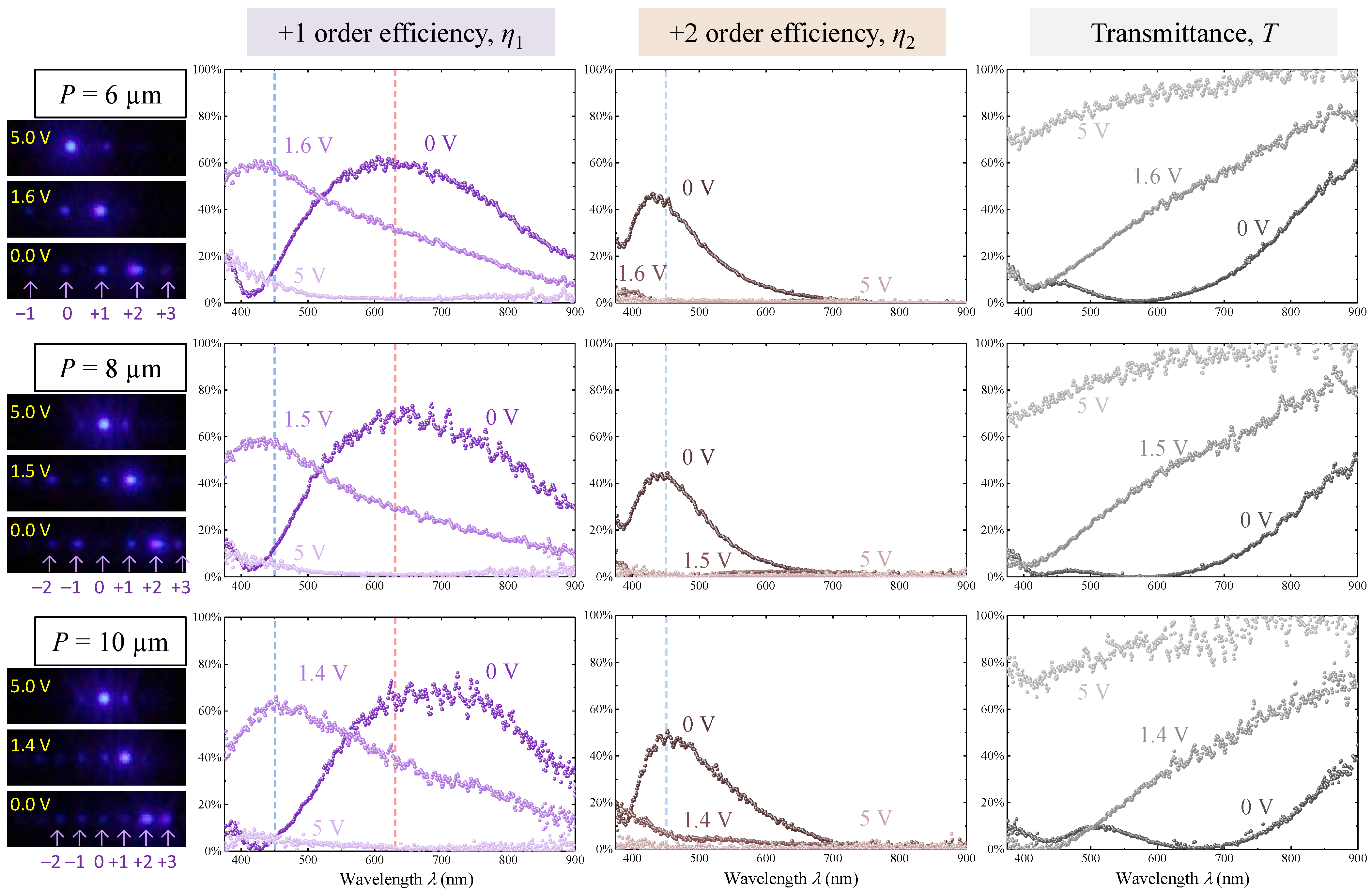
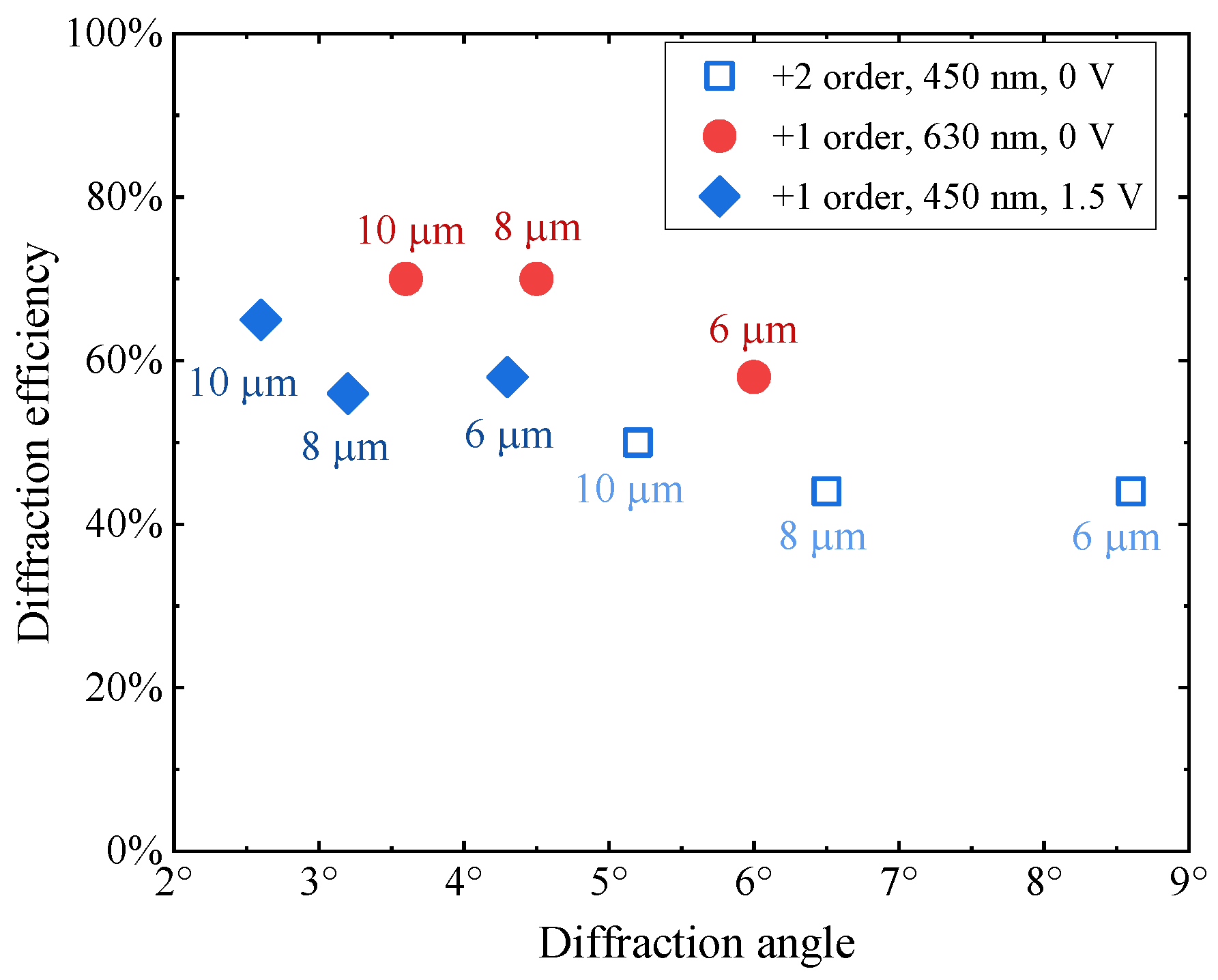
3.2. Diffraction Efficiency Measurements

To reveal the actual diffractive performance of the fabricated LC-metasurfaces, we used the BFP-spectrometry technique [23], allowing the extraction of quantitative information on the spectra of efficiencies η n of all observable diffraction orders. The technique relies on the digital processing of scanned and spectrally resolved BFP images of metasurfaces using also a spectrally resolved reference beam image obtained under the same conditions at a homogeneous LC-cell area.
In BFP, the x-coordinate of a light spot created by an n-th diffraction order is determined by the diffraction angle as x n = H sin α n , where H is the only unknown experimental device parameter to be once empirically determined for all registered BFP images. Resolving diffraction efficiencies is based on the assumption that a metasurface BFP image expressed as intensity I ( x , λ ) can be presented as a sum of reference beam intensities I 0 :
I ( x , λ ) = n η n ( λ ) I 0 ( x x n , λ ) ,
with the latter shifted along the x-axis in the BFP according to Bragg’s law (1).
Scanning and spectral resolving of the metasurface BFP images was carried out using the same custom setup based on the Olympus BX53MTRF optical microscope and the Ocean Optics QE Pro fiber optic spectrometer as described in Ref. [23]. Spatial scanning was performed by mechanically displacing the input port of the spectrometer fiber with a stepper motor actuator controlled by an Arduino microprocessor board. By interpolating and fitting the measured intensity maps I ( x , λ ) with Equation (2) we resolved the spectra of efficiencies of all observable orders of diffraction.
To study the diffraction at intermediate voltage, we applied 1.0 kHz rectangular voltage waveforms to the transparent ITO electrodes. Using alternating voltage is conventional for electrically driven LC devices, as it allows the avoidance of the accumulation of free charges at the electrodes and LC cell heating. By observing BFP images at voltages at and about 1.5 V (used in optimization) we noticed that slightly different 1.4 V or 1.6 V voltages sometimes allow the achievement of higher target efficiencies. Therefore, we empirically determined optimal intermediate voltages separately for each metasurface, as is indicated everywhere below. To achieve a transparent mode, we applied a voltage of 5 V.
In this way, we quantified the diffractive properties of all three fabricated elements in three different modes and we summarize them in Figure 3. One can see that the obtained efficiency spectra fully confirm our theoretical expectations. The observed +1 order diffraction efficiencies reach or exceed 60% for red light at zero voltage and for blue light at the intermediate voltage. The efficiencies of +2 diffraction order reach their maximum values, approaching almost 50% at about the target blue light wavelength. In the intermediate modes, all three metasurfaces diffract blue light into +1 order with a 60% efficiency. In the transparent mode induced by a 5 V voltage, the diffraction at target wavelengths is suppressed. The particular experimental diffraction efficiency values at the target wavelengths are 5–10% lower than theoretically predicted (compare, e.g., Figure 2a with the bottom row in Figure 3). The difference is especially noticeable in the blue range and we attribute it to an inevitable loss of light energy due to scattering on the LC orientation fluctuations and defects.
To visualize the advantages of multiplexing, we used Equation (1) to evaluate the diffraction angles covered by three studied metasurfaces at the target blue and red light wavelengths and present the corresponding efficiencies in Figure 4 as functions of this angle. The diagram follows the well-known general trend of less efficient diffractive performance at larger angles formulated for LC gratings [4]. It is inevitable, as LCs always smoothen sharp phase flyback areas and the relative contribution of these distorted areas increases as the grating period shortens, to provide diffraction at larger angles. At the same time, it is seen in Figure 4 that the three studied multiplexed elements cover the range up to 7 by 8 rather evenly spread deflection angles, and the largest deflection angle approaches 9 . Naturally, the particular values of these angles are defined by Bragg’s law (1) and can be fine-tuned to particular desired values in this range by adjusting the metasurface periods.

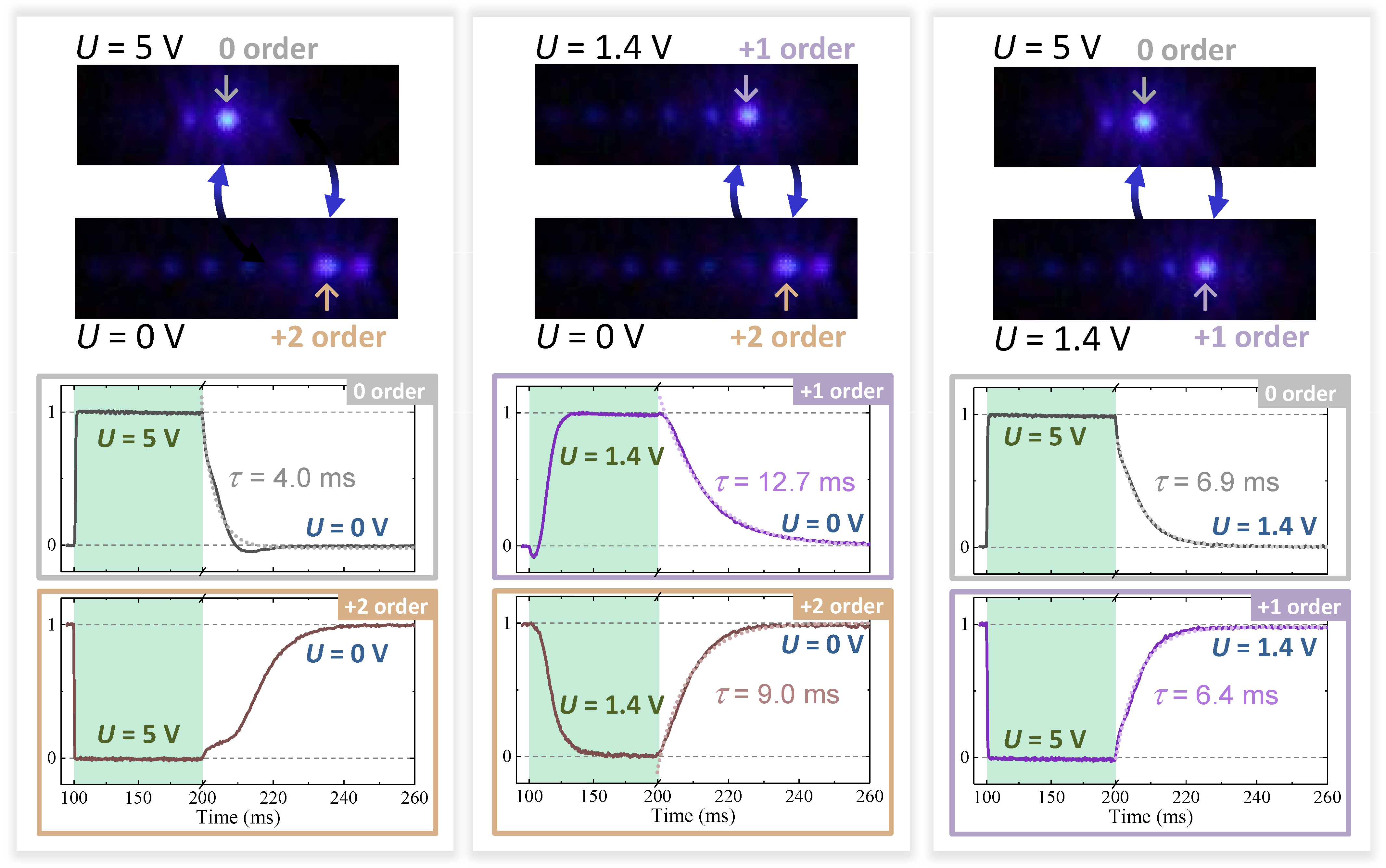
3.3. Switching Speed

The speed of switching between different operating modes is a key characteristic of beam-steering elements. To reveal the dynamics of electro-optics of fabricated LC-metasurfaces, we studied them using a custom setup based on an Olympus CX31PF-5 microscope (built-in objective 0.25 NA) using a semiconductor laser diode (wavelength 445 nm) as a light source, and a silicon photodiode for the signal registration, see Ref. [23] for more details. The diode light was polarized along the y-axis and focused into a spot smaller than the metasurface size. A pinhole diaphragm with a 1 mm aperture was placed in front of the registering diode to separate and independently analyze different diffraction orders.
To study the transitions between all three operating modes, we applied 100 ms long rectangular pulses of a higher amplitude of 5 V and of intermediate amplitude in the range 1.4–1.6 V depending on the metasurface period. In order to investigate the transition between the intermediate and higher voltage modes, we applied more complex pulses with a background voltage equal to the intermediate voltage and, again, square 100 ms long pulses of higher voltage of 5 V. All three elements of different periodicity switch very similarly. We present in Figure 5 exemplary data for the somewhat slower 10 μ m periodic metasurface. For all three switching processes, the dynamics of diffraction channels dominant in the corresponding modes is presented. To purify the relaxation character, we normalized the registered optical power by the values in both steady states.
One can see that the transition to higher-voltage mode is very fast when starting from the zero-voltage or intermediate-voltage modes: the diffraction is rapidly suppressed and the direct transmission grows equally fast. Such behavior is typical for many LC systems and it is determined by a large excess of dielectric LC energy [24]. Switching to the intermediate-voltage mode from the zero-voltage mode is slower, as the corresponding dielectric energy excess (quadratic in voltage) is much smaller.
As is also typical for electro-optical LC systems, the overall speed is determined by the time scale of relaxation after the voltage is decreased or fully switched off. The relaxation is driven by the excess of LC deformation energy and the switching speed is determined by the balance between elastic and counteracting viscous forces [24]. As was thoroughly analyzed for single-sided LC-metasurfaces [19,20], in the most general scenario, the relaxation dynamics is multiexponential: complex LC deformations occur on different spatial scales, giving rise to very different deformation energies, and their subsequent exponential relaxation is superimposed in the optically observable dynamics. Here, in the double-sided design, we also clearly observe the exponential relaxation character. As shown by the dotted plots in Figure 5, it is possible to closely approximate five out of six relaxations by exponents e Δ t / τ , where Δ t is the time passed since the voltage is decreased in amplitude or switched off, and the characteristic relaxation time τ is a fitting parameter. The particular values of the latter are indicated on the plots in Figure 5. One can also trace the general multiexponential character of the relaxation as, for instance, the direct transmission (0-order) relaxes after the voltage of 5 V is fully switched off or decreased down to 1.4 V with similar, but nevertheless different, times of 4.0 ms and 6.9 ms, correspondingly.
The slowest relaxation apparently occurs as +2 order intensity is restored after full switching off of the higher 5 V voltage. One can clearly see that this process takes place in two steps. Although the direct transmission rapidly disappears, the blue light is firstly redirected into +1 diffraction order while +2 order stays dim. Only after this first stage is accomplished in about 10 ms, does further LC relaxation take place, resulting in complete restoration of +2 order. Note that even in this exceptional case, one can estimate the switching time by 20 ms, which is close to the switching time of a uniform display cell containing the same LC material in the same geometry. Switching off all other diffraction orders dominant in different operating modes occurs at least twice as fast.

4. Conclusions

We have shown that multiplexed beam-steering elements can be realized as double-sided LC metasurfaces that are switchable by voltages of several volts within ten milliseconds. The design of such metasurfaces based on binary alignment patterns imprinted on both substrates relies on elaborate numerical optimization, accounting for all specific details of experimental realization. Our measurements fully confirm the key theoretical expectations and demonstrate the feasibility of efficient diffractive and spectral multiplexing.
The choice of target wavelengths of blue and red light for the color multiplexing is dictated by commercially available laser diode sources. Clearly, one can similarly optimize the deflection of light of any visible wavelength. The lower wavelength limit is fixed by the LC material properties: the E7 nematic mixture (as typical for LCs in general) exhibits strong absorption in the near ultraviolet range. The upper wavelength limit is not so definite, but one has to ensure that the LC layer thickness is sufficiently large for the light to accumulate the required phase modulation. A straightforward scaling-up of the design will likely cause negative side effects, such as slowed down switching, increased driving voltage and compromised LC alignment quality. Using one of the recently developed LC mixtures [30,31] exhibiting larger optical anisotropy in the near infrared range will allow the performance of efficient beam steering at such wavelengths, keeping the cell gap relatively small.
From the practical point of view, the great advantage of the proposed device is its full compatibility with existing LC display technology. Indeed, the flat device geometry as well as its main constituents—substrates coated with transparent ITO electrodes and rubbed polymer alignment layers, and a 4 μ m thick layer of typical nematic LC—are standard for display cells. The only difference is fine FIB processing of certain substrate areas, which can be easily included as an additional step to the conventional production line. The true merits of this kind of compatibility have recently been demonstrated by the remarkably fast success of Kymeta antennas performing beam steering in the radio frequency range [32].
Finally, we note that the potential functionalities offered by the newly developed platform of LC-metasurfaces are certainly not exhausted by beam steering. Following the same strategy, they can be equally successfully optimized for numerous other optical applications requiring the electrically controlled deflecting, splitting, and focusing of visible light.

Author Contributions

Conceptualization, M.V.G., A.R.G. and A.V.M.; design optimization, A.V.M.; substrate patterning, V.V.A. and M.V.G.; LC cell assembly and switching dynamics characterization, I.V.S. and I.V.K.; optical diffraction measurements, A.A.E.; writing—original draft preparation, M.V.G.; writing—review and editing, all authors; funding acquisition, M.V.G. All authors have read and agreed to the published version of the manuscript.

Funding

The research is funded by the Russian Science Foundation (project 18-12-00361). https://rscf.ru/project/18-12-00361/ (accessed on 8 December 2022). Equipment of Shared Research Center of FSRC “Crystallography and Photonics” RAS supported by the Ministry of Science and Higher Education of the Russian Federation was used.

Data Availability Statement

The data supporting the findings of this study are available from M.V.G. upon reasonable request.

Acknowledgments

We are grateful to Serguei P. Palto for numerous fruitful discussions and advice, to Mikhail V. Egorenkov for the kind assistance with BFP spectrometry, and to Alexander A. Antonov for consulting on graphic design.

Conflicts of Interest

The authors declare no conflict of interest. The funders had no role in the design of the study; in the collection, analyses, or interpretation of data; in the writing of the manuscript; or in the decision to publish the results.

Abbreviations

The following abbreviations are used in this manuscript:
BFPBack focal plane
FIBFocused ion beam
ITOIndium tin oxide
LCLiquid crystal
LiDARLight detection and ranging
POMPolarizing optical microscopy

References

  1. Chan, V.W.S. Free-Space Optical Communications. J. Light. Technol. 2006, 24, 4750–4762. [Google Scholar] [CrossRef]
  2. Hu, Y.; Chen, Q.; Feng, S.; Zuo, C. Microscopic fringe projection profilometry: A review. Opt. Lasers Eng. 2020, 135, 106192. [Google Scholar] [CrossRef]
  3. Behroozpour, B.; Sandborn, P.A.M.; Wu, M.C.; Boser, B.E. Lidar System Architectures and Circuits. IEEE Commun. Mag. 2017, 55, 135–142. [Google Scholar] [CrossRef]
  4. McManamon, P.F.; Bos, P.J.; Escuti, M.J.; Heikenfeld, J.; Serati, S.; Xie, H.; Watson, E.A. A Review of Phased Array Steering for Narrow-Band Electrooptical Systems. Proc. IEEE 2009, 97, 1078–1096. [Google Scholar] [CrossRef]
  5. Li, N.; Ho, C.P.; Xue, J.; Lim, L.W.; Chen, G.; Fu, Y.H.; Lee, L.Y.T. A Progress Review on Solid-State LiDAR and Nanophotonics-Based LiDAR Sensors. Laser Photonics Rev. 2022, 16, 2100511. [Google Scholar] [CrossRef]
  6. He, Z.; Gou, F.; Chen, R.; Yin, K.; Zhan, T.; Wu, S.T. Liquid Crystal Beam Steering Devices: Principles, Recent Advances, and Future Developments. Crystals 2019, 9, 292. [Google Scholar] [CrossRef] [Green Version]
  7. Morris, R.; Jones, C.; Nagaraj, M. Liquid Crystal Devices for Beam Steering Applications. Micromachines 2021, 12, 247. [Google Scholar] [CrossRef]
  8. Lio, G.E.; Ferraro, A. LIDAR and Beam Steering Tailored by Neuromorphic Metasurfaces Dipped in a Tunable Surrounding Medium. Photonics 2021, 8, 65. [Google Scholar] [CrossRef]
  9. Wang, X. Performance evaluation of a liquid-crystal-on-silicon spatial light modulator. Opt. Eng. 2004, 43, 2769. [Google Scholar] [CrossRef]
  10. Manko, A.; Kim, Y.; Morozov, A.; Palto, S.; Won, K.; Lee, H.S. Optimization of Optical Phase Profile in Beam Deflector with Advanced Simulation Method for High Diffraction Efficiency. Micromachines 2022, 13, 802. [Google Scholar] [CrossRef]
  11. Li, Y.; Luo, Z.; Wu, S.T. High-Precision Beam Angle Expander Based on Polymeric Liquid Crystal Polarization Lenses for LiDAR Applications. Crystals 2022, 12, 349. [Google Scholar] [CrossRef]
  12. Li, H.; Zhou, C.; Lee, W.B.; Choi, D.Y.; Lee, S.S. Flat telescope based on an all-dielectric metasurface doublet enabling polarization-controllable enhanced beam steering. Nanophotonics 2021, 11, 405–413. [Google Scholar] [CrossRef]
  13. Shang, X.; Tan, J.Y.; Willekens, O.; Smet, J.D.; Joshi, P.; Cuypers, D.; Islamaj, E.; Beeckman, J.; Neyts, K.; Vervaeke, M.; et al. Electrically Controllable Liquid Crystal Component for Efficient Light Steering. IEEE Photonics J. 2015, 7, 1–13. [Google Scholar] [CrossRef]
  14. Shang, X.; Trinidad, A.M.; Joshi, P.; Smet, J.D.; Cuypers, D.; Smet, H.D. Tunable Optical Beam Deflection Via Liquid Crystal Gradient Refractive Index Generated By Highly Resistive Polymer Film. IEEE Photonics J. 2016, 8, 1–11. [Google Scholar] [CrossRef]
  15. Nersisyan, S.R.; Tabiryan, N.V.; Steeves, D.M.; Kimball, B.R. The Promise of Diffractive Waveplates. Opt. Photonics News 2010, 21, 40. [Google Scholar] [CrossRef]
  16. Nys, I.; Stebryte, M.; Ussembayev, Y.Y.; Beeckman, J.; Neyts, K. Tilted Chiral Liquid Crystal Gratings for Efficient Large-Angle Diffraction. Adv. Opt. Mater. 2019, 7, 1901364. [Google Scholar] [CrossRef]
  17. Kim, J.; Oh, C.; Serati, S.; Escuti, M.J. Wide-angle, nonmechanical beam steering with high throughput utilizing polarization gratings. Appl. Opt. 2011, 50, 2636. [Google Scholar] [CrossRef]
  18. Kasyanova, I.V.; Gorkunov, M.V.; Artemov, V.V.; Geivandov, A.R.; Mamonova, A.V.; Palto, S.P. Liquid Crystal Metasurfaces on Micropatterned Polymer Substrates. Opt. Express 2018, 26, 20258–20269. [Google Scholar] [CrossRef]
  19. Gorkunov, M.V.; Kasyanova, I.V.; Artemov, V.V.; Ezhov, A.A.; Mamonova, A.V.; Simdyankin, I.V.; Palto, S.P. Liquid-Crystal Metasurfaces Self-Assembled on Focused Ion Beam Patterned Polymer Layers: Electro-Optical Control of Light Diffraction and Transmission. ACS Appl. Mater. Interfaces 2020, 12, 30815–30823. [Google Scholar] [CrossRef]
  20. Gorkunov, M.V.; Kasyanova, I.V.; Artemov, V.V.; Ezhov, A.A.; Mamonova, A.V.; Simdyankin, I.V.; Palto, S.P. Superperiodic Liquid-Crystal Metasurfaces for Electrically Controlled Anomalous Refraction. ACS Photonics 2020, 7, 3096–3105. [Google Scholar] [CrossRef]
  21. Artemov, V.V.; Khmelinin, D.N.; Mamonova, A.V.; Gorkunov, M.V.; Ezhov, A.A. Microscopic Studies of Alignment Layers Processed by a Focused Ion Beam for the Creation of Liquid Crystal Metasurfaces. Crystallogr. Rep. 2021, 66, 673–681. [Google Scholar] [CrossRef]
  22. Kasyanova, I.V.; Gorkunov, M.V.; Palto, S.P. Liquid-crystal metasurfaces: Self-assembly for versatile optical functionality. Europhys. Lett. 2021, 136, 24001. [Google Scholar] [CrossRef]
  23. Gorkunov, M.V.; Mamonova, A.V.; Kasyanova, I.V.; Ezhov, A.A.; Artemov, V.V.; Simdyankin, I.V.; Geivandov, A.R. Double-sided liquid crystal metasurfaces for electrically and mechanically controlled broadband visible anomalous refraction. Nanophotonics 2022, 11, 3901–3912. [Google Scholar] [CrossRef]
  24. Blinov, L.M. Structure and Properties of Liquid Crystals; Springer: Dordrecht, The Netherlands, 2011. [Google Scholar] [CrossRef]
  25. Pestov, S.; Vill, V. Liquid Crystals. In Springer Handbook of Materials Data; Springer: Cham, Switzerland, 2018; pp. 959–991. [Google Scholar] [CrossRef]
  26. König, T.A.F.; Ledin, P.A.; Kerszulis, J.; Mahmoud, M.A.; El-Sayed, M.A.; Reynolds, J.R.; Tsukruk, V.V. Electrically tunable pasmonic behavior of nanocube-polymer nanomaterials induced by a redox-active electrochromic polymer. ACS Nano 2014, 8, 6182–6192. [Google Scholar] [CrossRef] [PubMed]
  27. Tkachenko, V.; Abbate, G.; Marino, A.; Vita, F.; Giocondo, M.; Mazzulla, A.; Ciuchi, F.; Stefano, L.D. Nematic Liquid Crystal Optical Dispersion in the Visible-Near Infrared Range. Mol. Cryst. Liq. Cryst. 2006, 454, 263665–271673. [Google Scholar] [CrossRef]
  28. Geivandov, A.R.; Kasyanova, I.V. Device for Alignment of Microstructures on Two Substrates with Micrometric Precision. Prib. Tekhnika Eksperimenta 2020, 6, 130–132. (In Russian) [Google Scholar] [CrossRef]
  29. Color Glass Spectral Transmittance. Available online: http://www.crystaltechno.com/Crystaltechno_Color_Glass_Spectral_Tramsmittance_2019_03_10.pdf (accessed on 8 December 2022).
  30. Zou, J.; Yang, Z.; Mao, C.; Wu, S.T. Fast-Response Liquid Crystals for 6G Optical Communications. Crystals 2021, 11, 797. [Google Scholar] [CrossRef]
  31. Bennis, N.; Jankowski, T.; Strzezysz, O.; Pakuła, A.; Zografopoulos, D.C.; Perkowski, P.; Sánchez-Pena, J.M.; López-Higuera, J.M.; Algorri, J.F. A high birefringence liquid crystal for lenses with large aperture. Sci. Rep. 2022, 12, 14603. [Google Scholar] [CrossRef]
  32. Sazegar, M.; Stevenson, R. Holographic Metasurface Antennas with Dynamic Beam Pointing and Polarization Control. In Proceedings of the 2020 IEEE International Symposium on Antennas and Propagation and North American Radio Science Meeting, Montreal, QC, Canada, 5–10 July 2020; pp. 1657–1658. [Google Scholar] [CrossRef]
Figure 1. Advantages of multiplexed beam-steering elements based on LC-metasurfaces. Schematic of an array of 9 electrically controlled elements of different periods for parallel +1 order diffraction deflection at 9 different angles (a). Schematic of an array of 3 multiplexed metasurfaces covering 9 different angles by virtue of spectral and diffractive multiplexing (b). Schematic of a cell containing self-assembled double-sided LC metasurface (c). Three operating modes of a multiplexed element based on a double-sided LC-metasurface at different voltages imparting sawtooth modulations to the blue and red light wavefronts (d).
Photonics 09 00986 g001
Figure 2. Optimized multiplexed 10 μ m periodic double-sided LC-metasurface. Numerically obtained spectra of diffraction efficiencies of +1 and +2 orders, and direct transmittance at three different voltages with the target wavelengths of 450 nm and 630 nm indicated by vertical dashed lines (a). Colormaps of the simulated spatial distribution of the LC director polar angle within one metasurface period at three voltages (b).
Photonics 09 00986 g002
Figure 3. Measured visible light diffraction by experimental double-sided LC-metasurfaces of periods 6 μ m (top row), 8 μ m (middle row) and 10 μ m (bottom row). Three operations modes of each metasurface are illustrated by the corresponding BFP POM images upon blue light illumination and the spectra of diffraction efficiencies of +1 and +2 orders and the direct transmittance. Target wavelengths of 450 nm and 630 nm are indicated by the vertical dashed lines.
Photonics 09 00986 g003
Figure 4. Diffraction angle dependence of the efficiencies of +2 order (hollow symbols) and +1 order (filled symbols) manifested by the three fabricated LC-metasurfaces at the target wavelengths of 450 nm (blue symbols) and 630 nm (red symbols) with the metasurface periods indicated.
Photonics 09 00986 g004
Figure 5. Switching dynamics of the 10 μ m periodic LC-metasurface between its three operation modes. Blue-light BFP POM images obtained at three voltages are shown with the dominant orders indicated. Normalized time-resolved intensity variation of the diffraction orders dominating in the corresponding modes are presented with the time intervals of 100 ms long rectangular switching voltage pulses indicated by light-green background. The best exponential fits of the relaxation dynamics are plotted as dotted lines and the corresponding relaxation times τ are specified.
Photonics 09 00986 g005
Table 1. Parameters of stripe patterns to be imprinted by FIB on both LC-cell substrates as obtained by the numerical optimization described in Section 2 for three metasurface periods. The stripe beginning and end x-coordinates are given together in parentheses. All values are in micrometers.
PeriodStripes on Top SubstrateStripes on Bottom Substrate
6(0.0, 3.7) (3.9, 4.1) (4.2, 4.5) (4.7, 4.8)(0.0, 0.9) (1.0, 1.4) (1.7, 1.8) (1.9, 2.0) (2.3, 2.4)
8(0.0, 5.9) (6.5, 6.7) (6.9, 7.0)(0.0, 1.1) (1.3, 1.8 ) (2.2, 2.4) (2.7, 2.9)
10(0.0, 6.4) (6.5, 6.7) (7.0 7.6) (7.8, 8.1) (8.3, 8.4) (8.8, 9.0)(0.0, 1.5) (1.8, 2.4) (2.8, 3.0) (3.2, 3.3) (3.7, 3.8) (4.1, 4.3)
Publisher’s Note: MDPI stays neutral with regard to jurisdictional claims in published maps and institutional affiliations.

