1. Introduction
High-energy pulsed fiber lasers are in high demand for many applications, such as micromachining, lidars, etc. In particular, Er-doped fiber lasers are of great interest for lidar applications, where operation in the eye-safe spectral region is preferable. The main limitation for maximum pulse energy (which typically define maximum scanning distance for lidars) comes from a maximum achievable peak power, limited by non-linear effects (depending on pulse width and spectral width it could be Raman scattering, four-wave mixing and, in some cases, Stimulated Brillouin Scattering). However, for a long pulse with a duration of more than a few hundred nanoseconds, the maximum extractable energy is typically limited by the maximum energy that could be stored in the active fiber. Near the limit appearance of strong amplified spontaneous emission (ASE) becomes the main limitation for pulse energy growth [
1]. The most obvious way to increase the maximum extractable energy is to enlarge the active core diameter. In particular, the maximum pulse energy of ~1–1.5 mJ was reported for fibers with 35–40 μm core diameter [
1,
2,
3]. Such a diameter is still small enough to achieve the operation with a nearly diffraction-limited beam quality (M
2 < 1.65). An increase in the pulse energy up to 3 mJ became possible by the utilization of fibers with a 60 μm core [
4] and trading off the beam quality (M
2~3.8). Further scaling of the output pulse energy up to 8–17 mJ requires the utilization of active fibers with a core diameter of 100 μm [
5,
6]. In this case, the beam quality degrades down to M
2~9–16.
The possibility of increasing the pulse energy up to 3.85 mJ, while keeping the diffraction-limited beam quality (M
2 < 1.2), was reported recently in [
7]. The authors used a 1480 nm core-pumped, Er-doped fiber amplifier with a 50 μm core diameter. This result, being compared with previous works, seems to be quite outstanding. Moreover, the utilization of the same amplifier scheme with Er-doped fiber having a 35 μm core diameter allowed us to achieve only 0.73 mJ of pulse energy [
8]. The Er-doped area in [
7] is twice as large compared to our fiber in [
8], so it is quite natural to expect a corresponding growth of the maximum output pulse energy. A similar result was presented in [
9], where the maximum pulse energy of 1.3 mJ was achieved by pumping Er-doped (Yb-free) phosphate-glass gain fiber with a Raman fiber laser at 1480 nm. Despite that there is no direct information about active core diameter, we estimated it as ~45–47 μm from the mode field area (1000 μm
2) and a suggestion of the perfect step-index profile. Again, the ratio between energy and the core area is much smaller in [
9] as compared to [
7]. The huge pulse energy demonstrated in [
7] might be a feature of the utilization of a very broadband seed source (50 nm linewidth); however, it is also possible that the achieved energy was overestimated by authors of [
7]. Indeed, the measurement of the power within the pulse (in-pulse) and that between the pulses (inter-pulse) was made with the help of a gating acousto-optic modulator followed by a splitter, which delivered a signal to a photodetector and optical spectrum analyzer. To collect light, authors of [
7] used single-mode fiber; however, the Er-doped fiber with 50 μm was not intrinsically single-mode, and in-pulse and inter-pulse signal power could have a very different distribution between the guided modes of the Er-doped fiber core. Signals propagated in different modes could have a very different collection efficiency by the registration system in [
7]. In particular, the in-pulse signal belonged to the amplified signal and propagated mainly in the fundamental mode (as proven by the high beam-quality factor). The in-pulse signal would be efficiently collected by the registration system placed near the fiber axis. Inter-pulse signal mainly consisted of the ASE generated in the amplifier, and its power will be distributed between all the modes, propagating in the core of the 50-μm-Er-doped fiber. Thus, the collection efficiency of the inter-pulse signal by the registration system in [
7] could be quite small, and, as a consequence, part of power propagating in ASE could be significantly underestimated.
It must be noted that most applications (such as wind Doppler lidars, CO
2 detectors and many others) require a narrowband pulse signal. Thus, a laser with a 50 nm-wide-signal spectrum is not suitable for them, even if the 3.8 mJ energy reported in [
7] is correct. Therefore, the maximum achievable pulse energy for a relatively narrow-band seed signal (with FWHM less than a few nm) is still below 1.5 mJ for diffraction-limited amplifiers (M
2 < 1.65) [
1,
2,
3]. It should be noted that no noticeable progress in increasing the pulse energy in the above-mentioned amplifiers was observed in the last decade. It is quite clear that technology based on the utilization of amplifiers based on standard step-index optical fibers has exhausted itself. Thus, a further increase in energy in single-mode lasers is possible only through the use of novel designs of active optical fibers.
In recent years, a very promising approach to increasing core diameter in an amplifier with a diffraction-limited beam quality based on tapered fibers has been proposed and intensively studied [
10,
11,
12,
13,
14,
15,
16,
17,
18,
19]. The core and cladding diameters of such fibers increase along the fiber length to a value several times larger than the initial diameter. The core diameter at the thin fiber end is typically chosen to be small enough to support only the fundamental mode. A slow adiabatic increase in the core diameter along the fiber length ensures that the signal, coupled into the fundamental mode at the thin tapered fiber end, will propagate toward the thick tapered fiber end without excitation of high-order-modes (HOM) [
18]. In our recent work, we have demonstrated a tapered Er-doped fiber amplifier with an output core diameter of ~100 μm and diffraction-limited beam quality (M
2 < 1.35) [
16,
17]. Keeping in mind the large pulse energy achieved in the 100 μm-core Er-doped fibers [
5,
6], the tapered fiber seems to be a promising tool for increasing maximum pulse energy in diffraction-limited beam-quality Er-doped amplifiers. The aim of the current work was to study the possibility for scaling output energy using this approach.
2. Experimental Set-Up
The fiber chosen for the experiment was drawn from the same preform as the fiber reported in [
17]. It consists of a core, square-shaped pure-silica cladding and a secondary cladding made of an F-doped silica layer. The refractive index profile at the thick fiber end is shown in
Figure 1a. It was measured in the fiber with an outer diameter of ~125 μm with the help of NR-9200HR Optical Fiber Analyzer (EXFO, Québec City, QC, Canada) and then was rescaled to the dimension of the tapered fiber at the thick end. The fiber diameter at the thin end was equal to 70 μm, which corresponds to the core diameters of 16.5 μm (the estimated cut-off wavelength relative to the silica cladding was ~1.6 μm). The average first cladding diameter was about 50 μm, corresponding to the core/first-cladding ratio of ~1/3. The small size of the first cladding resulted in difficulties with the first HOM evacuation. To suppress the cladding mode and HOMs excited at the splice point, we fabricated a cladding mode stripper (CMS) ~30 cm away from the input thin end of the tapered fiber (the first 30 cm from the thin end has a nearly constant diameter, so the cladding modes did not couple into the core). The thin end of the fiber was bent with a diameter of ~10 cm to evacuate the first HOM from the core as well. The output end fiber diameter was 365 μm, which corresponds to the output end core diameter of 86 μm. The net tapered fiber length was 3.2 m. The dependence of the diameter on the fiber length measured with an optical microscope (by observing from the side at a different position along the length) is shown in
Figure 1b.
The scheme of the laser set-up is shown in
Figure 2. As a seed, we used a polarized super luminescent fiber laser source (SFLS) followed by a fiber Filter with FWHM of ~1 nm centered at 1550 nm. This source was chosen to generate a perfect CW signal (without the high-frequency modulation typical for CW fiber laser based on fiber Bragg gratings) and to exclude the appearance of stimulated Brillouin scattering (which is an issue, when seed is a single frequency DFB semiconductor diode). This signal was modulated by a semiconductor optical amplifier (SOA). The peak power of our SOA was limited by 10 mW, so pulses with a 1 kHz repetition rate and 5 μs duration have an average power of only 0.05 mW. To amplify such a small signal, we used a core-pumped Er-doped fiber amplifier (EDFA) based on EDF-4/125-50PM (FORC-Photonics, Moscow, Russia), which increased signal power to few mW. Then we placed an acousto-optical modulator (AOM), synchronized with SOA to clean up the pulses from ASE by direct suppression of the inter-pulses signal. Note that the whole scheme up to AOM was based on polarization-maintaining fiber (only one signal polarization was propagated) as both SOA and AOM were polarization sensitive. Net signal loss in AOM was about ~10 dB, so additional core-pumped EDFA was placed after AOM (after this point, we built a polarization-insensitive scheme). The Er-doped fiber used in this amplification stage has a core diameter of ~14 μm (EDF-14/125-35 from FORC Photonics) to increase maximum extractable energy. It must be noted that for a pulse repetition rate of 1 kHz and average power of 10 mW, the pulse energy reached 10 μJ, and a further increase in pulse energy resulted in the appearance of a significant ASE signal. For this reason, we used double-clad (DC) Er-doped (Yb-free) fiber (EDF-DC-35/125-100 fiber from FORC Photonics) pumped through the cladding in the last amplification stage (DC EDFA). This amplification stage (i.e., Er-doped fiber) was similar to the one reported in [
1]. To completely suppress the inter-pulse signal, we placed an additional filter before DC EDFA and kept maximum pulse energy at the output of the DC EDFA to be below 0.3 mJ to guarantee minimum generated inter-pulse ASE. Measurements of inter-pulse power were done by an integrating photodetector (I-PD). This technique was discussed in detail in [
1]; in particular, its high accuracy in obtaining pulse energy in presence of CW or quasi-CW signal was proven. The measurement confirms that inter-pulse energy in our seed was below the accuracy of our measurements (~2%).
The developed narrowband pulsed laser was used as a seed source for the amplifier, based on the tapered Er-doped fiber (T-EDF). The signal was coupled to the thin end of the T-EDF. The pump at 976 ± 0.5 nm was coupled through the thick T-EDF end in the backward direction. The thick end was angle-polished at 7 degrees to exclude backward reflection. As T-EDF had F-doped secondary cladding, no additional efforts were required to make the thick end compatible with the end-pumping. A dichroic mirror (DM) was placed at 45 degrees after the lens was used to separate the pump from the amplified signal (reflection from DM was insensitive to the polarization of the pump and signal).
The amplified signal was analyzed by a power meter, integrating the photodetector (I-PD) and optical spectrum analyzer (OSA). The scheme for signal analysis is shown in
Figure 2b. The amplified signal was propagated in a collimated beam toward to sensor of the power meter. The power meter sensor also acted as a diffusor and reflected a small part of the signal power incident on it in random directions. A 360-μm-core multimode fiber (MMF) with a core numerical aperture (NA) of about 0.22 was used to collect light reflected by the power meter sensor. The MMF was placed far enough from the sensor to be able to collect light from the whole sensor area. Such a detection scheme was utilized to guarantee that regardless of the spatial distribution of ASE and amplified signal inside the collimated beam I-PD will collect part of ASE and the signal proportional to their actual net power. Single-mode fiber (SMF) was placed into the center of the beam to collect a small part of the amplified signal and deliver it to OSA. An example of a signal detected by the I-PD (in the presence of strong ASE) is presented in
Figure 2c. The typical optical spectrum of the amplifier signal is shown in the inset in
Figure 2c.
3. Results
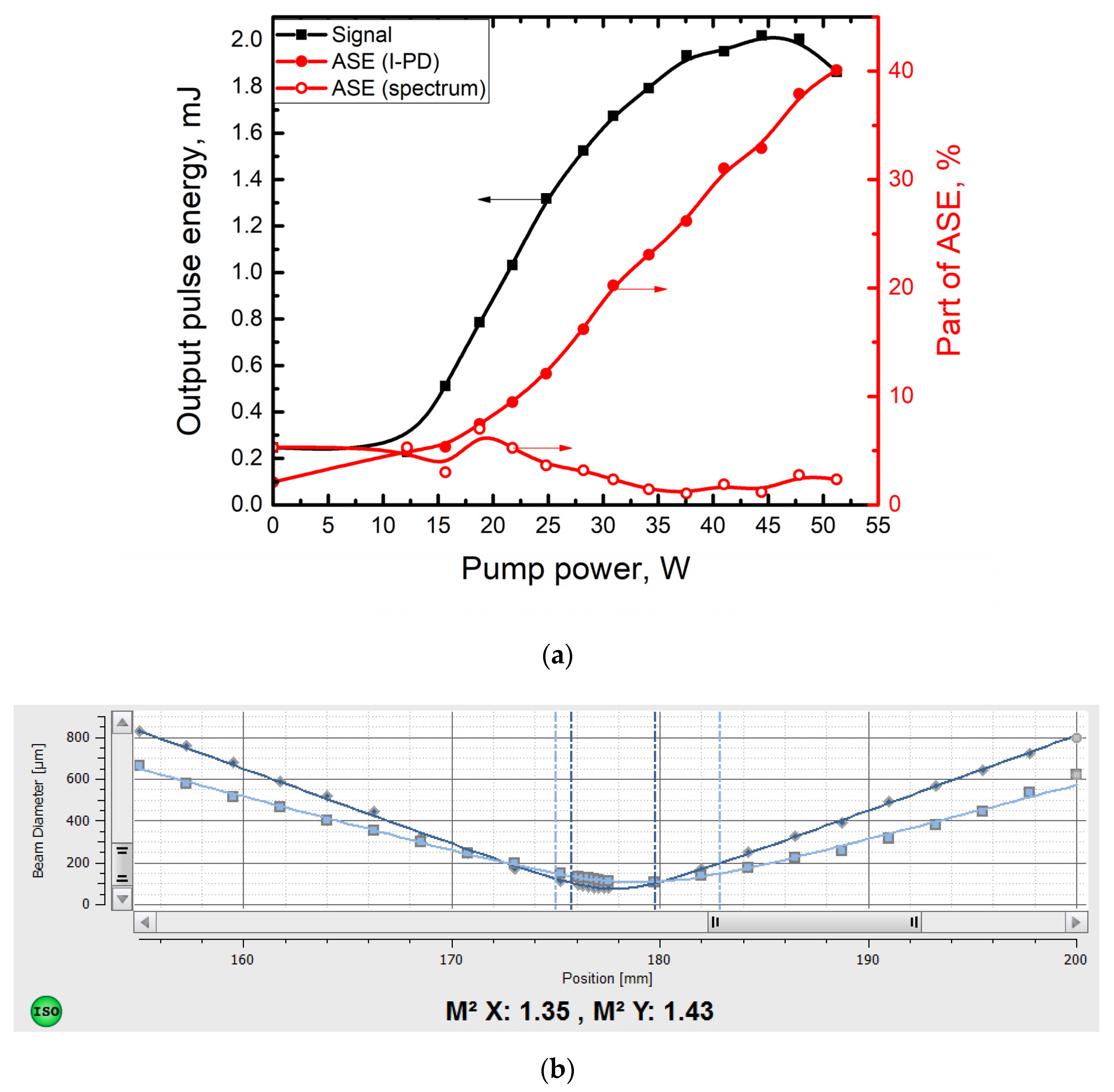
To reveal the maximum pulse energy which could be extracted from the T-EDF, we tested its performance in the amplifier scheme. The T-EDF was pumped with a semiconductor pump diode pigtailed by fiber with a core diameter of 105 μm and core NA ~ 0.15. The maximum output power of the pump diode used in this experiment was ~51 W. Input signal had an average power of 300 mW, a pulse repetition rate of ~1 kHz, and a pulse duration of ~5 μs. The pulse energy of the amplified signal, calculated using measurements of average output power, repetition rate, and part of the in-pulse power obtained with the I-PD, is shown in
Figure 3a by solid black squares. In the same Figure, we plot part of ASE, calculated using the signal from I-PD (solid red circles) and measurements of the optical spectrum by OSA (open circles). In the last case, we calculated part of ASE as a ratio of the net power of the signal with a wavelength outside the 5 nm band centered at 1550 nm to the net signal power in the whole spectral range. A seed power of 300 mW (0.3 mJ pulse energy) was enough to saturate the amplifier—no noticeable change in the maximum achieved energy was observed even for input power reduced down to 50 mW (pulse energy 0.05 mJ).
The output beam quality was measured in the T-EDF in the CW regime (the modulation of SOA and AOM was switched off) using Thorlabs M2MS-BP209IR2 dual scanning-slit beam profiler (Thorlabs, Newton, NJ, USA). At a maximum pump power of ~51 W, the beam quality factor, M
2, was found to be below 1.43 (see
Figure 3b). Note that some deterioration of the beam quality was due to the presence of a central dip in the refractive index profile, which could noticeably increase M
2 even for a perfect single-mode propagation regime [
17].
The obtained energy of 2 mJ is the record high for narrow-band (with spectral width below a few nm) Er-doped amplifiers operated with diffraction-limited beam quality. As indicated in the introduction, the maximum energy reported to date for such amplifiers was ~1–1.5 mJ [
1,
2,
3]. Nevertheless, it is much smaller than could be expected, keeping in mind the maximum core diameter (~86 μm). Indeed, compared to the results obtained for Er-doped fibers with 100 μm core and taking into consideration the growth of energy with the increase in the Er-doped area, we expected to achieve pulse energy on the level ~6 mJ. We suggest that a possible reason for the three times smaller pulse energy could be non-uniform signal distribution across the core of the T-EDF. As can be seen from
Figure 1a, the fundamental mode has the maximum near the fiber axis, but its intensity drops to nearly zero at the core-cladding interface. We suggest that near the core-cladding interface excitation of Er
3+ ions could be not completely removed during the amplified pulse propagation. In this case, HOMs with a maximum intensity located near the core-cladding interface, have an optimal condition for amplification, and ASE build-up mainly occurs in such HOMs.
Results of the measurements of the signal part, propagated in ASE, made by I-PD and OSA indirectly confirm our suggestion about the propagation of ASE in high-order modes. Indeed, a strong discrepancy between the part of ASE obtained with I-PD and using OSA could be seen in
Figure 3a. Part of ASE calculated using signal spectra even reduces with an increase in the pump power, and such behaviors are completely different from that observed using I-PD (ASE rapidly grows with pump power and reaches 40%). The reason for that was indicated in the Introduction, while anomalously high energy, measured in [
7], was discussed. As we suggest, the amplified signal and ASE have different distributions across the modes propagating in the core of the T-EDF. As a result, ASE (which propagates in HOMs) has much smaller collection efficiency by single-mode fibers placed into the center of the beam as compared to the amplified signal power, which propagated in the fundamental mode. I-PD is free from such mode selectivity as it detects signal reflected from the Power meter, which acts as a diffusor—this means that all the modes gave equal impact to the signal collected by I-PD.
To check our suggestion, we did an additional experiment. The thin part of the tapered fiber was cut-off at the position where the clad diameter reaches 110 μm (core diameter ~26 μm), and the seed was coupled into the thin end of the tapered fiber. Due to the large input core diameter, not only the fundamental mode, but also LP
11, LP
12, and LP
02 groups of HOMs could propagate in the thin part of the T-EDF and will be excited during splicing with the seed laser. As a result, signal distribution across the core becomes more uniform, and the inversion of the Er
3+ ions will be removed with higher efficiency. Indeed, measurements of the pulse energy of the amplified signal demonstrate a pulse energy increase up to 3.3 mJ (see
Figure 4a). This value is much closer to energy, which we expect to obtain from uniform fiber with an Er-doped core diameter of ~86 μm (>6 mJ). Additionally, we should take into account a smaller volume of the tapered fiber core compared to uniform fiber with the same output core diameter and length, as only the core at the thick end has a diameter of 86 μm and at all other positions along the fiber the core diameter is smaller. The calculation of the average area along the T-EDF and its comparison with a core area at the thick end gives us an estimation of maximum extractable energy of about 3.6 mJ, which is quite close to the obtained value. It could be seen that a strong discrepancy between the part of ASE, calculated with I-PD and with OSA, is still observed—we suggest that a significantly different distribution between the propagating modes of amplified signal and of ASE is realized in this case too.
Finally, we checked that the results of works [
5,
6], where 100-μm-core Er-doped fibers were studied, could be repeated in our set-up. For this aim, we used a multi-mode Er-doped fiber with a core/clad dimension of ~90/125 μm. The fiber had a design identical to that published in work [
20] but it had a two times smaller Er content (the optimal length of the fiber was increased to 30 m). The fiber was tested in an all-fiber amplifier scheme with a co-propagated pump and signal coupled into the fiber using a pump-and-signal combiner (similar to the amplifier built in [
20]). In this case, we used a seed with an average power of about 0.3 W, a repetition rate of about 2.5 kHz and pump source with maximum available power of 105 W. With our multi-mode Er-doped fiber, we succeed in achieving maximum pulse energy of 7.5 mJ, which is quite comparable with the results of [
5,
6]. It is also interesting that in this case, part of ASE, measured with I-PD and using OSA, perfectly matches. It is quite clear that the reason for such behavior is a good mode mixture during propagation through the 30-m-long Er-doped fiber. In this case, signal and ASE are uniformly distributed across the propagating modes and thus both techniques give identical results.
4. Discussion
As could be seen from the previous section, the utilization of tapered fibers allows for an increase of maximum achievable pulse energy. In particular, pulses with an energy of 2 mJ, a narrow-band spectrum (~1 nm) and a nearly diffraction-limited output beam quality were demonstrated (the previous state-of-the-art record for such type of amplifiers was 1–1.5 mJ [
1,
2,
3]). However, the maximum pulse energy is smaller than was expected initially. There are two main factors that limit the maximum pulse energy extractable from T-EDF. The first one is a signal distribution across an area doped with Er
3+ ions. The operation of the T-EDF in a single-mode regime results in reduced light intensity at the core-cladding interface. As a consequence, an optimal condition for the amplification of ASE in HOMs was created. If the de-excitation of Er
3+ ions is not very efficient during pulse propagation, the ASE build-up occurs in this part of the core cross-section, which strongly limits the maximum achievable pulse energy. The second factor is a smaller amount of Er
3+ ions compared to a uniform fiber having the same length and a constant core and cladding diameters equal to that of a T-EDF thick end (core volume in the tapered fiber could be twice as small as compared to a uniform fiber with the same output core diameter). Thus, to achieve higher pulse energy, it is necessary to perform some optimization of the tapered fiber design. The first possible method is the utilization of confined doping combined with optimization of the refractive index profile. It should help to achieve high electric field intensity in all the regions of the fiber cross-section doped with Er
3+ ions. In this case, de-excitation of the Er
3+ ions during pulse propagation will be more efficient and conditions for the generation of strong ASE will appear at higher pulse energy. However, a reduction in the Er-doped area will also reduce maximum extractable energy, so very tight control of the fiber parameters would be required. The second method is a modification of the tapered fiber longitudinal profile. In this case, the length of the tapered fiber should mostly have a core and cladding diameter close to its maximum value, and only a short section of the fiber should have a conic profile. If such a condition is met–the maximum extractable energy will become close to that in the regular fiber having a similar output core diameter.
One more important result of the current work is a comparison of different techniques for detecting the part of optical power propagating in ASE. We have shown that a huge error could happen if a signal is collected by a single-mode fiber from the output beam of the amplifier, which is not intrinsically single-mode. An important factor that must be taken into consideration during such measurements is a different distribution over the propagating modes of the amplified signal (which typically propagates in the fundamental mode mainly) and ASE, which could propagate mainly in HOMs. Thus, the accurate detection of the part of ASE requires the utilization of a technique that collects light uniformly from all the propagating modes. In the current work, for this aim, we utilized the scheme of an integrating photodetector and collected the light that was reflected from the diffusor (in our case, it was the power meter) illuminated by the collimated beam.
Another possible technique for the direct measurements of the pulse energy is that the utilization of a pyroelectric energy meter (used in [
9]) is free from the above mention error, as energy meter is directly measuring energy propagating in the signal mode. However, it might have another disadvantage. As could be seen from
Figure 2c (and also could be found in [
1]) the ASE in high-energy amplifiers has a pulsed nature. As a consequence, if the ASE reaches the sensor of the energy meter, it will increase energy meter readings and in such a way, it will result in the overestimation of the signal pulse energy. For this reason, we did not use this technique in our study.

 ,
, 


