Communication

Transverse Anderson Localization Enhancement for Low-Filling-Rate Glass–Air Disordered Fibers by Optimizing the Diameter of Air Holes

1
School of Computer and Communication Engineering, Changsha University of Science and Technology, Changsha 410114, China
2
School of Materials Science and Engineering, Peking University, Beijing 100871, China
3
Key Laboratory of Optoelectronics and Telecommunication of Jiangxi Province, Department of Photoelectric, Information Science and Engineering, Jiangxi Normal University, Nanchang 330022, China
*
Author to whom correspondence should be addressed.
Photonics 2022, 9(12), 905; https://doi.org/10.3390/photonics9120905
Submission received: 28 October 2022 / Revised: 20 November 2022 / Accepted: 24 November 2022 / Published: 26 November 2022
(This article belongs to the Special Issue Specialty Optical Fibers and Their High-Power Applications)

Abstract

:
We demonstrate a method to enhance the transverse Anderson localization (TAL) effect of the glass–air disordered optical fiber (G-DOF) by adjusting the number and diameter of air holes. This method does not need to enlarge the air-filling fraction of G-DOF, leading to the mitigation of fabrication complexity. By choosing the appropriate diameter and number of air holes, the average localized beam radius of G-DOF with the highest air-filling fraction of 30% can be successfully reduced by 18%. Moreover, the proposed method is always functional for the situations of the air-filling fraction lower than 50%. We also identify that, under the same air-filling fraction, a larger number of air holes in the G-DOF leads to the smaller standard deviation of the corresponding localized beam radius, indicating a stable fiber structure. The results will provide new guidance on the G-DOF design.

1. Introduction

The disordered optical fiber (DOF) is a new type of optical fiber that relies on the transverse Anderson localization (TAL) effect to confine and transmit beams [1]. Unlike traditional optical fibers, it has no core and cladding structure [2]. The material effective refractive index is randomly distributed across the fiber cross-section. Thus, the beam can be transmitted along the fiber regardless of the position of the fiber cross-section on which it is launched. Those characteristics mean that the DOF has good application prospects in the fields of high-quality imaging [3,4,5,6], random laser generation [7], beam multiplexing [8], and so on.
The first DOF was reported in 2012 [9]. It was fabricated by randomly mixing 40,000 pieces of polymethyl methacrylate fibers and 40,000 pieces of polystyrene fibers. The DOF was first used for image transmission in 2014 and achieved a higher imaging quality in comparison with some of the best commercial multicore fibers [7], thus attracting extensive attention. In past decades, four kinds of DOFs composed of different materials have been investigated—polymer DOF [10], glass–air DOF [11], Tellurite DOF [12,13,14] and chalcogenide DOF [15,16]—in order to cover the different transmission windows including visible light [4,17], near-infrared [12,18], and mid- infrared light [16], respectively. However, the transmission distances of all those fibers are only several centimeters [19], which is a major disadvantage that hinders their practical application. Generally, researchers believe the glass–air DOF (G-DOF) can be widely used sooner than other types of DOF. Firstly, glass has lower transmitting attenuation compared with other materials, making it easier to achieve long-distance transmission. Secondly, the effective refractive index difference between glass and air is large, which contributes to a stronger TAL effect [20,21] It is worth mentioning that, so far, one kind of G-DOF with ~30% air-filling fraction has the longest transmission distance of about 90 cm [17,22]. Although the TAL effect of DOF will be the strongest by increasing the air-filling fraction to 50%, it will make the fabrication challenging [23].
In this study, for a specific air-filling fraction, we adjust the diameter and number of the air holes arising in the G-DOF in order to reinforce its TAL effect. This method successfully reduced the average localized beam radius by about 18% for the G-DOF with the air-filling fraction of 30%. Additionally, this method always works for the DOF with the air-filling fraction less than 50%. The arrangement of this article is as follows. In Section 2, the schematic topology of the proposed G-DOF is presented. In Section 3, the impacts of the air hole diameter and number on the average localized beam radius are investigated and analyzed in detail. Finally, a brief conclusion is summarized in Section 4.

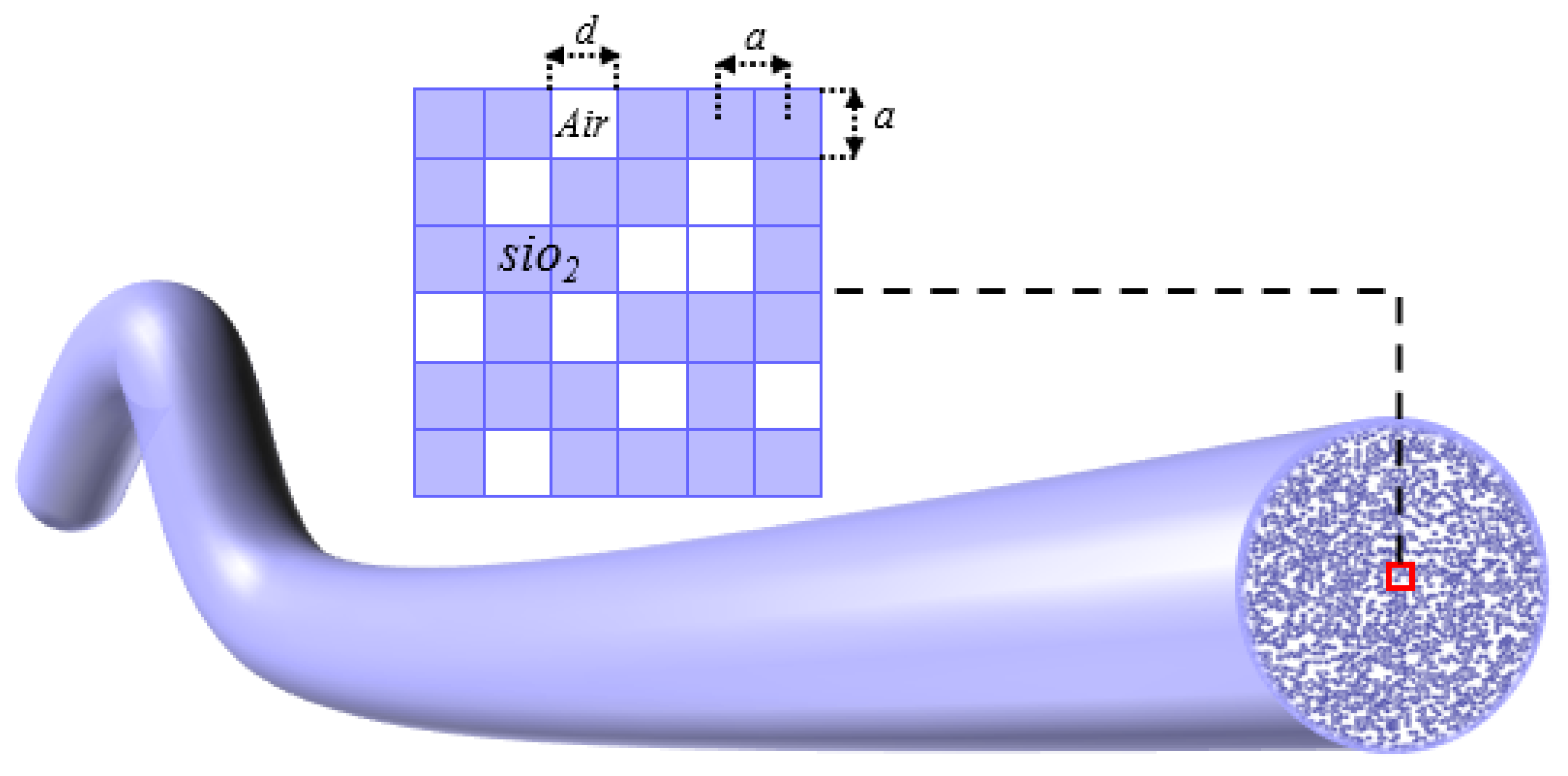
2. Schematic Topology and Design Principle

Figure 1 shows an example of a cross-section of G-DOF with square elements used for our numerical simulations, the purple part represents SiO2 and the white part denotes air holes. We can see that the material on the cross-section of fiber distributed randomly. For the ease of observation, we zoom in on the center of the fiber, as shown in the upper part of Figure 1. Here, we need to explain that we choose the square elements instead of circular elements because the circular elements cannot be closely arranged without any gap.
The modeling of the DOF is constructed as below. First, we divide the transverse cross-section into several tiny square elements. If we assume that the total number of the square elements is N, the width of the square elements and the distance between the two nearby elements are both equal to a. Then, the materials of those squares are all set as SiO2. Secondly, we pick X elements from the total number of N (0 ≤ XN), to reset their size to d (0 ≤ da) and their material property to air. Here, to ensure the air-filling fraction f remains constant, X and d should fulfill the function of f = Xd2/Na2. Obviously, the relationship between X and d is the opposite. The smaller diameter d of the air hole is, the larger the number X is. It should be mentioned that the previous studies only considered the case of air hole diameter d equal to a. However, the impact of air hole diameter on the TAL effect is not comprehensively investigated, when d is smaller than a.

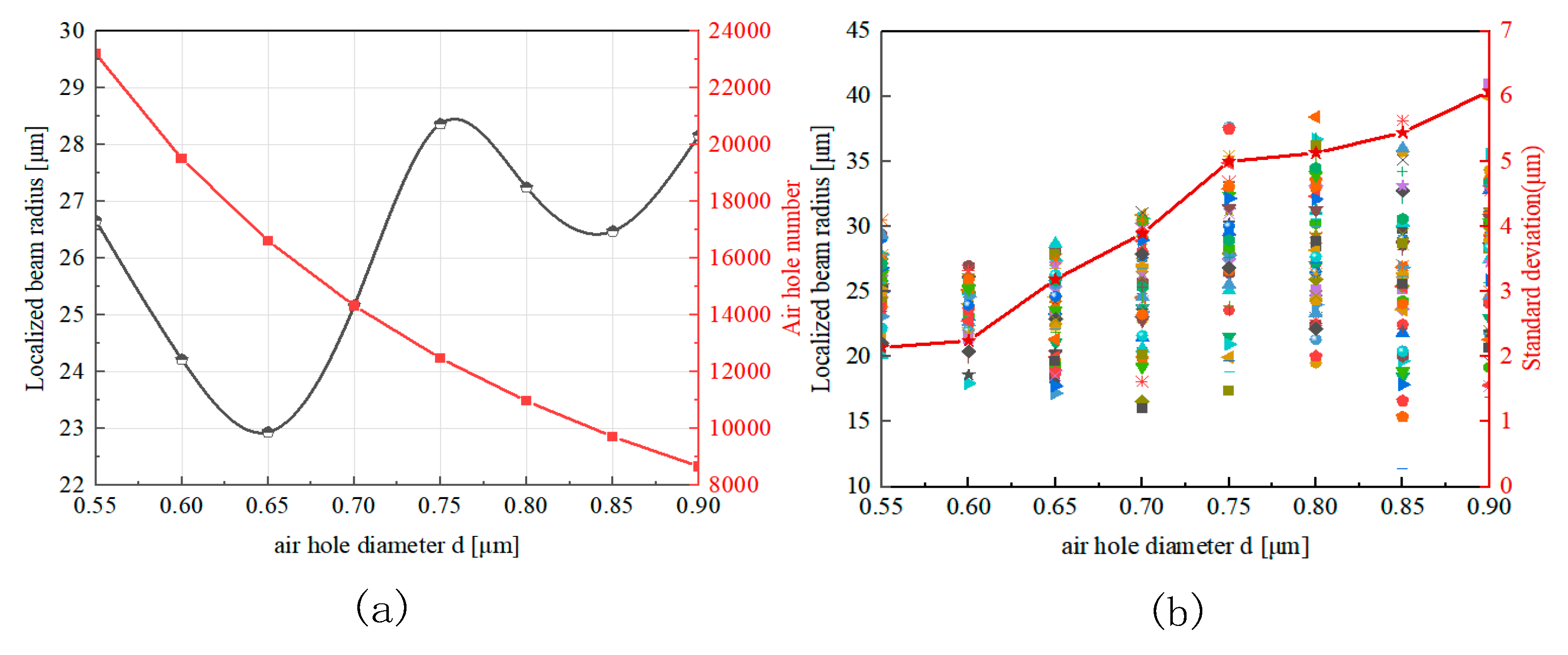
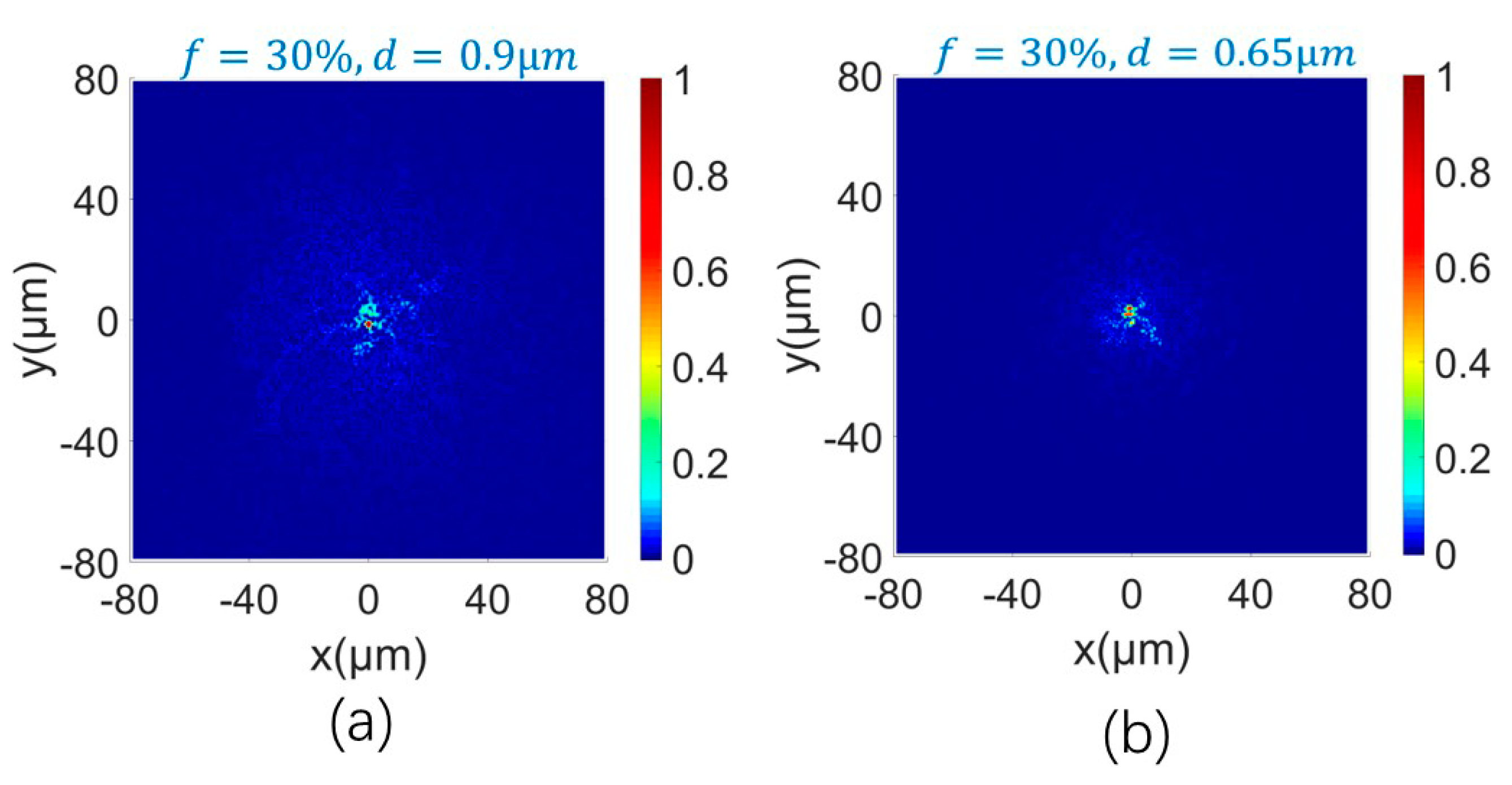
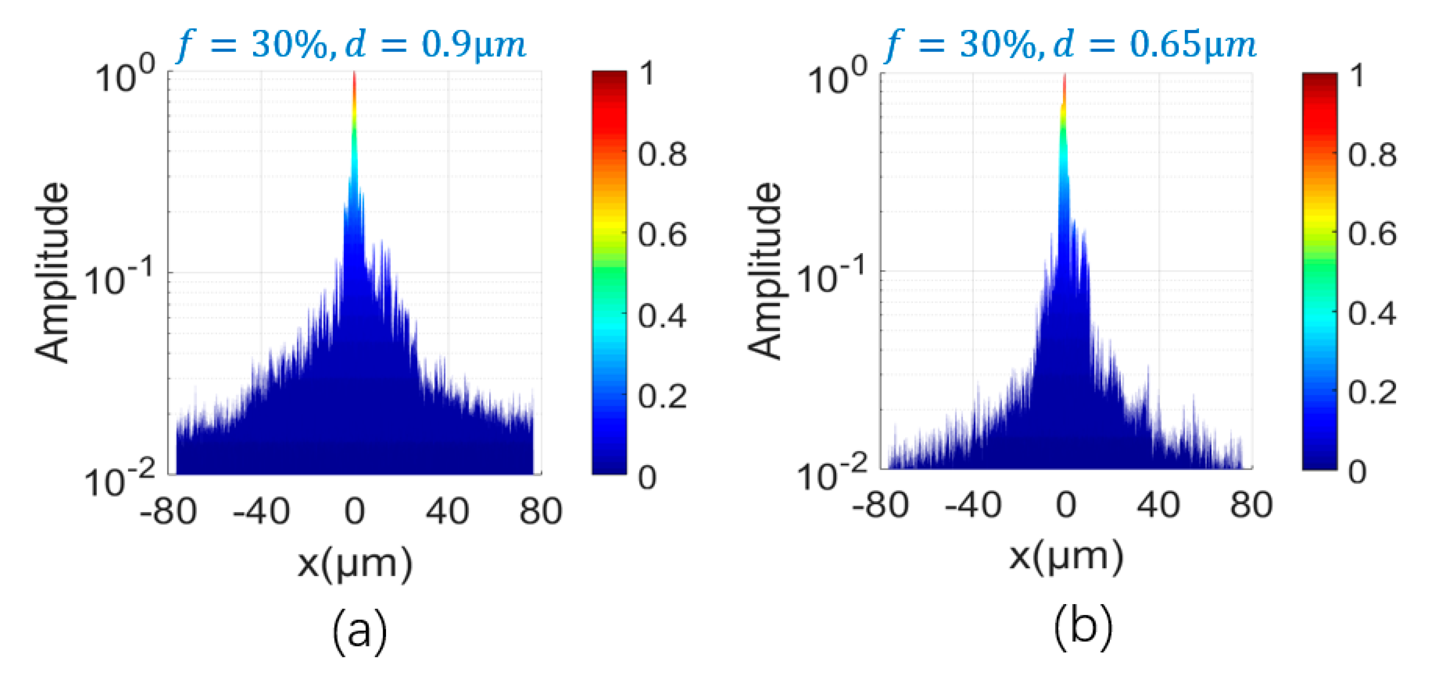
3. Simulation Procedure and Data Analysis

The initial simulation parameter settings are N = 170 × 170 = 28,900 and a = 0.9 μm, while a Gaussian beam with a diameter of 4.25 μm at the wavelength of 633 nm is launched into the fiber center. Based on those parameter settings, the optical field distribution and the localized beam radius after the light transmission over the 2 cm DOF with different sets of (d, X) can be calculated by using Rsoft software based on the finite-difference beam propagation method (FD-BPM). Here, we choose 2 cm transmission distance, because the beam spreading will become relatively stable after such a distance.
Figure 2a presents the relationship between the diameter d and the number X of the air holes, and the influence of different sets of (d, X) on the average localized beam radius, when the air-filling fraction f is fixed to 30%. For each set of (d, X), the average localized beam radius was calculated based on 50 different DOF models. It can be seen from the curve with square marks in Figure 2a that the air hole diameter d and the air hole number X are inversely proportional, when the air-filling fraction remains constant. From the curve with circle marks in Figure 2a, we can see that, when the diameter of air holes maintains the initial setting of d = a = 0.9 μm and X = 8640, the average beam radius is around 28 μm. However, when d = 0.65 μm and X = 16,622 are satisfied, the corresponding average beam radius can be reduced to about 23 μm. This result indicates that, for a specific air-filling fraction of G-DOF, we still can improve the strengthen of the TAL effect simply by adjusting the number and diameter of air holes.
Figure 2b shows the localized beam radius and the standard deviation of the localized beam radius of 50 different fiber models with different air hole diameters of d, when the air hole filling rate is f = 30%. It is interesting to find that, when the air hole diameter decreases, the standard deviation of the localized beam radius decreases gradually. It reflects that the structure of the fiber becomes stable due to the growing number of air holes for smaller diameter. This phenomenon can be explained as follows: with the decrease in the air hole diameter, the number of air holes must increase to ensure the constant air-filling rate f. From the statistical perspective, while the number of air holes increases, the distribution of the air holes will present increased randomness close to the design purpose. Additionally, the randomly generated models obey the same random distribution, thus the difference of localized beam radius is reduced. This finding will facilitate the realization of structurally stable DOF designs. Therefore, by regulating the air hole diameter d from 0.9 μm to 0.65 μm, the G-DOF can achieve not only stronger TAL effect but also better structural stability.
For the ease of performance comparison, Figure 3 and Figure 4, respectively, show the optical field intensity distributions on the xy plane and the xz plane for the DOFs with different air hole diameter of d = a = 0.9 μm and d = 0.65 μm. We can clearly observe that the beam spreading range is smaller under the condition of d = 0.65 μm, in comparison with the case under the condition of d = 0.9 μm, indicating of a stronger TAL effect.
Furthermore, we investigate the impact of combined parameters (d, X) on the average localized beam radius, when the air-filling fractions are set at 20%, 30%, 40%, and 50%, respectively, as shown in Figure 5a. It is obvious that when f = 20%, 30%, 40%, and 50% are satisfied, the DOF has the minimum average beam radius at d = 0.55 μm, 0.65 μm, 0.85 μm, and 0.9 μm, respectively. Accordingly, it implies that when the air-filling fraction f is less than 50%, there exists a parameter set of (d, X) to minimize the beam radius. However, when the air-filling fraction f reaches 50%, we cannot find a better value of (d, X) to further reduce the localized beam radius, because the fiber with initial setting has already reached its maximum disorder, and further increasing the number of air holes will reduce the degree of disorder. As shown in Figure 5b, we can see that no matter what air-filling fraction f is, the greater number of air holes the fiber contains, the smaller the corresponding mean square deviation of the beam localization radius would be.

4. Conclusions

We have presented a new method to improve the TAL effect and structural stability of the G-DOF by manipulating the air hole diameter and number, without changing the air-filling fraction. The impact of the air hole diameter and number on the localized beam radius of G-DOFs has been analyzed in detail, when the air-filling fraction is fixed at 20%, 30%, 40% and 50%, respectively. Theoretical results indicate that there is always a better combination of air hole diameter and number to further reduce the localized beam radius, for the case of an air-filling fraction no more than 50%. Meanwhile, our method can successfully reduce the beam radius of the G-DOF with the highest air-filling fraction of 30%. In addition, the greater the number of air holes the fiber contains, the smaller the corresponding mean square deviation of the beam localization radius would be, which means the fiber structure is more stable. This research provided a new perspective for the optimal design of G-DOF.

Author Contributions

Conceptualization and methodology J.Z. (Jiajia Zhao), Y.Z. and C.H.; software, validation and writing—original draft preparation, J.Z. (Jiajia Zhao) and Y.Z.; data analysis, J.Z. (Jiajia Zhao); investigation, Y.M. and W.C.; writing—review and editing, J.Z. (Jinshuai Zhang) and H.L.; funding acquisition, J.Z. (Jiajia Zhao) and H.L. All authors have read and agreed to the published version of the manuscript.

Funding

This work is supported by the Natural Science Foundation of Hunan Province of China (Grant No. 2020JJ5606), National Natural Science Foundation of China (Grants 11804133), Scientific Research Fund of Hunan Provincial Education Department (21B0279) and the International Cooperative Extension Program of Changsha University of Science and Technology, China (Grant No. 2019IC35).

Institutional Review Board Statement

Not applicable.

Informed Consent Statement

Not applicable.

Data Availability Statement

The data are available upon request.

Conflicts of Interest

The authors declare no conflict of interest.

References

  1. Mafi, A.; Tuggle, M.; Bassett, C.; Mobini, E.; Ballato, J. Advances in disordered transverse Anderson localizing optical fibers. arXiv 2019. preprint. [Google Scholar]
  2. Mafi, A.; Ballato, J. Review of a Decade of Research on Disordered Anderson Localizing Optical Fibers. Front. Phys. 2021, 9, 681. [Google Scholar] [CrossRef]
  3. Hu, X.; Zhao, J.; Antonio-Lopez, J.E.; Fan, S.; Correa, R.A.; Schulzgen, A. Robust Imaging-Free Object Recognition through Anderson Localizing Optical Fiber. J. Light. Technol. 2020, 39, 920–926. [Google Scholar] [CrossRef]
  4. Karbasi, S.; Frazier, R.J.; Koch, K.W.; Hawkins, T.; Ballato, J.; Mafi, A. Image transport through a disordered optical fibre mediated by transverse Anderson localization. Nat. Commun. 2014, 5, 3362. [Google Scholar] [CrossRef] [PubMed] [Green Version]
  5. Zhao, J.; Sun, Y.; Zhu, Z.; Antonio-Lopez, J.E.; Correa, R.A.; Pang, S.; Schülzgen, A. Deep learning imaging through fully-flexible glass-air disordered fiber. ACS Photon. 2018, 5, 3930–3935. [Google Scholar] [CrossRef]
  6. Zhao, J.; Sun, Y.; Zhu, H.; Zhu, Z.; Antonio-Lopez, J.E.; Correa, R.A.; Pang, S.; Schülzgen, A. Deep-learning cell imaging through Anderson localizing optical fiber. Adv. Photon. 2019, 1, 066001. [Google Scholar] [CrossRef] [Green Version]
  7. Abaie, B.; Mobini, E.; Karbasi, S.; Hawkins, T.; Ballato, J.; Mafi, A. Random lasing in an Anderson localizing optical fiber. Light Sci. Appl. 2017, 6, e17041. [Google Scholar] [CrossRef] [PubMed] [Green Version]
  8. Karbasi, S.; Koch, K.W.; Mafi, A. Multiple-beam propagation in an Anderson localized optical fiber. Opt. Express 2013, 21, 305–313. [Google Scholar] [CrossRef] [PubMed] [Green Version]
  9. Karbasi, S.; Mirr, C.R.; Yarandi, P.G.; Frazier, R.J.; Koch, K.W.; Mafi, A. Observation of transverse Anderson localization in an optical fiber. Opt. Lett. 2012, 37, 2304–2306. [Google Scholar] [CrossRef] [PubMed]
  10. Karbasi, S.; Frazier, R.J.; Mirr, C.R.; Koch, K.W.; Mafi, A. Fabrication and Characterization of Disordered Polymer Optical Fibers for Transverse Anderson Localization of Light. J. Vis. Exp. 2013, 29, 50679. [Google Scholar] [CrossRef] [PubMed] [Green Version]
  11. Karbasi, S.; Hawkins, T.; Ballato, J.; Koch, K.W.; Mafi, A. Transverse Anderson localization in a disordered glass optical fiber. Opt. Mater. Express 2012, 2, 1496–1503. [Google Scholar] [CrossRef]
  12. Tuan, T.H.; Kuroyanagi, S.; Nagasaka, K.; Suzuki, T.; Ohishi, Y. Characterization of an all-solid disordered tellurite glass optical fiber and its NIR optical image transport. Jpn. J. Appl. Phys. 2019, 58, 032005. [Google Scholar] [CrossRef]
  13. Tuan, T.H.; Cheng, T.; Kuroyanagi, S.; Tanaka, S.; Nagasaka, K.; Suzuki, T.; Ohishi, Y. Fabrication of an all-solid tellurite disordered optical rod for transverse localization of light. In Proceedings of the Laser Applications Conference, Boston, MA, USA, 30 October–3 November 2016. [Google Scholar]
  14. Tuan, T.H.; Kuroyanagi, S.; Nagasaka, K.; Suzuki, T.; Ohishi, Y. Localization of light and transport of infrared optical image in a tellurite optical fiber with transversely-disordered refractive index profile. In Proceedings of the Conference on Lasers and Electro-Optics 2018, San Jose, CA, USA, 13–18 May 2018. [Google Scholar]
  15. Nakatani, A.; Tuan, T.H.; Isai, H.; Matsumoto, M.; Sakai, G.; Suzuki, T.; Ohishi, Y. Fabrication of chalcogenide transversely disordered optical fiber for mid-infrared image transport. In Proceedings of the Conference on Lasers and Electro-Optics 2020, San Jose, CA, USA, 10–15 May 2020. [Google Scholar]
  16. Suzuki, T.; Nakatani, A.; Tuan, T.H.; Ohishi, Y. Numerical investigation on local confinement of infrared light in chalcogenide transversely disordered optical fibers. In Proceedings of the Optical Components and Materials XVI 2019, SPIE, San Francisco, CA, USA, 2–7 February 2019. [Google Scholar]
  17. Zhao, J.; Lopez, J.E.A.; Zhu, Z.; Zheng, D.; Pang, S.; Correa, R.A.; Schülzgen, A. Image Transport through Meter-Long Randomly Disordered Silica-Air Optical Fiber. Sci. Rep. 2018, 8, 1–7. [Google Scholar] [CrossRef] [PubMed] [Green Version]
  18. Tuan, T.H.; Kuroyanagi, S.; Nagasaka, K.; Suzuki, T.; Ohishi, Y. Near-infrared optical image transport through an all-solid tellurite optical glass rod with transversely-disordered refractive index profile. Opt. Express 2018, 26, 16054–16062. [Google Scholar] [CrossRef] [PubMed]
  19. Turtaev, S.; Leite, I.T.; Altwegg-Boussac, T.; Pakan, J.M.; Rochefort, N.L.; Čižmár, T. High-fidelity multimode fibre-based endoscopy for deep brain in vivo imaging. Light Sci. Appl. 2018, 7, 1–8. [Google Scholar] [CrossRef] [PubMed]
  20. Karbasi, S.; Koch, K.W.; Mafi, A. Modal perspective on the transverse Anderson localization of light in disordered optical lattices. J. Opt. Soc. Am. B 2013, 30, 1452–1461. [Google Scholar] [CrossRef] [Green Version]
  21. Karbasi, S.; Koch, K.W.; Mafi, A. Image transport quality can be improved in disordered waveguides. Opt. Commun. 2013, 311, 72–76. [Google Scholar] [CrossRef]
  22. Zhao, J.; Antonio-Lopez, J.E.; Correa, R.A.; Mafi, A.; Windeck, M.; Schülzgen, A. Image transport through silica-air random core optical fiber. In Proceedings of the Conference on Lasers and Electro-Optics 2017, San Jose, CA, USA, 14–19 May 2017. [Google Scholar]
  23. Karbasi, S.; Mirr, C.R.; Frazier, R.J.; Yarandi, P.G.; Koch, K.W.; Mafi, A. Detailed investigation of the impact of the fiber design parameters on the transverse Anderson localization of light in disordered optical fibers. Opt. Express 2012, 20, 1869. [Google Scholar] [CrossRef] [PubMed]
Figure 1. The cross-section of G-DOF with square elements used for our numerical simulations.
Photonics 09 00905 g001
Figure 2. Under the condition of f = 30%, (a) the relationship between the diameter d and the number X of the air holes (red curve), and the influence of different sets of (d, X) on the average localized beam radius (black curve), (b) the localized beam radius and the standard deviation of the localized beam radius of 50 different fiber models with different diameter d.
Photonics 09 00905 g002
Figure 3. Optical field distribution diagram on the plane xy for fibers with different air hole diameter (a) d = a = 0.9 μm (b) d = 0.65 μm.
Photonics 09 00905 g003
Figure 4. Optical field distribution diagram on the plane xz for fibers with different air hole diameter (a) d = a = 0.9 μm (b) d = 0.65 μm.
Photonics 09 00905 g004
Figure 5. (a) When the air-filling fraction is fixed at 20%, 30%, 40% and 50%, the effects of different set of (d, X) on the average localized beam radius; (b) standard deviation of beam localization radius.
Photonics 09 00905 g005
Publisher’s Note: MDPI stays neutral with regard to jurisdictional claims in published maps and institutional affiliations.

