1. Introduction
Photonic-based THz systems have been intensively investigated for various applications, e.g., communications [
1,
2], spectroscopy [
3,
4] and imaging [
5], because they offer wide operational bandwidths, superior phase noise, and low loss transmission over long distances using optical fibers. For applications such as long-range THz communications, the high free-space path loss together with the limited transmit power, necessitate the use of high-gain directional THz antennas. This, in turn, requires photonic THz beam steering technologies which can be generally classified into two categories: namely frequency-steering using leaky-wave antennas (LWAs), and frequency independent steering using phased-array antennas. LWAs offer a quite attractive approach for THz beam steering, since the beam direction can be easily adjusted by tuning the operating frequency. Especially in combination with envelope detection, first high data rate mobile THz communications have been demonstrated [
6]. However, for THz spectroscopy or imaging applications, frequency independent photonic THz beam steering approaches are required. In [
7], fiber-based optical delay lines are used to adjust the time delays for a 1 × 4 photomixer array. This way, a maximum beam steering angle of 35° at 0.6 THz has been achieved. However, the fiber-based optical delay lines prevent compact integration. First, chip integrated delay lines using Mach–Zehnder-based switched delay lines for sub-THz range, were demonstrated, e.g., in [
8]. The disadvantage is that only discrete beam angles are supported, and for a high beam angle resolution, several 10 s of thermo-optical switches would be required, leading to a high-power consumption. Since the beam squint effect becomes less dominant in the THz domain [
9], optical phase shifters (OPSs) for phased-array antennas have also been investigated. Using OPSs based on thermo-optically controlled straight silica waveguides [
10], continuous beam steering at 0.3 THz is demonstrated, with a maximum steering angle of 50°. In this approach, only one heater is required for each OPS. However, the phase tuning efficiency of 0.24 W/π is relatively low.
Due to the low optical propagation losses, Si
3N
4/SiO
2-based TriPleX waveguides have been exploited for a number of applications, such as reconfigurable photonic RF filters [
11], high-granularity wavelength division multiplexers [
12], high-order ring resonators [
13] and programmable optical signal processor chips [
14]. Additionally, on-chip optical true time delays (TTDs) consisting of optical ring resonators (ORRs) are reported for continuous beam steering at microwave frequencies [
15,
16,
17]. Using the separate carrier tuning technique, the phase shift of the optical carrier can be adjusted to compensate for the nonlinearity of the phase response of TTDs [
18]. However, this approach is not easily scalable to THz frequencies, as the beam angle becomes much more sensitive to time delay variations at THz frequencies. As an example, a time delay variation of only 30 fs would lead to a beam deviation of ~1° at 0.3 THz. Consequently, to reach a constant time delay over a reasonable bandwidth, one would need to cascade a multifold of ORRs leading to higher power consumption, and substantially more complex control circuitry.
In this manuscript, we report on the design and experimental characterization of a TriPleX-based 1 × 4 OBFN chip with 4 OPSs for continuous beam steering at 0.3 THz. Each OPS consists of two cascaded ORRs. The fabricated OBFN chip enables the transfer of the optical phase shift to the THz domain, by optical heterodyne THz signal generation in high-frequency modified uni-traveling carrier photodiodes (MUTC-PDs). To support optical heterodyning, the ORRs are designed such that one laser signal is at the ORR’s resonance frequency, while the other optical carrier of the heterodyne signal is at the off-resonance frequency. The manuscript demonstrates experimentally that the fabricated 1 × 4 OBFN chip yields optical phase shifts up to 2π, with a tuning efficiency of 0.058 W/π. Furthermore, the inherent THz power variation during phase tuning due to the dispersive power transmission loss of the ORRs, is experimentally characterized at 0.295 THz. It is shown numerically using CST Studio Suite that these power variations only have a negligible impact on the steering angle. It is furthermore determined numerically that the maximum beam steering angle for a 1 × 4 phased array employing THz bow-tie antennas, is 62° at 0.295 THz.
2. Optical Beam Forming Network Chip
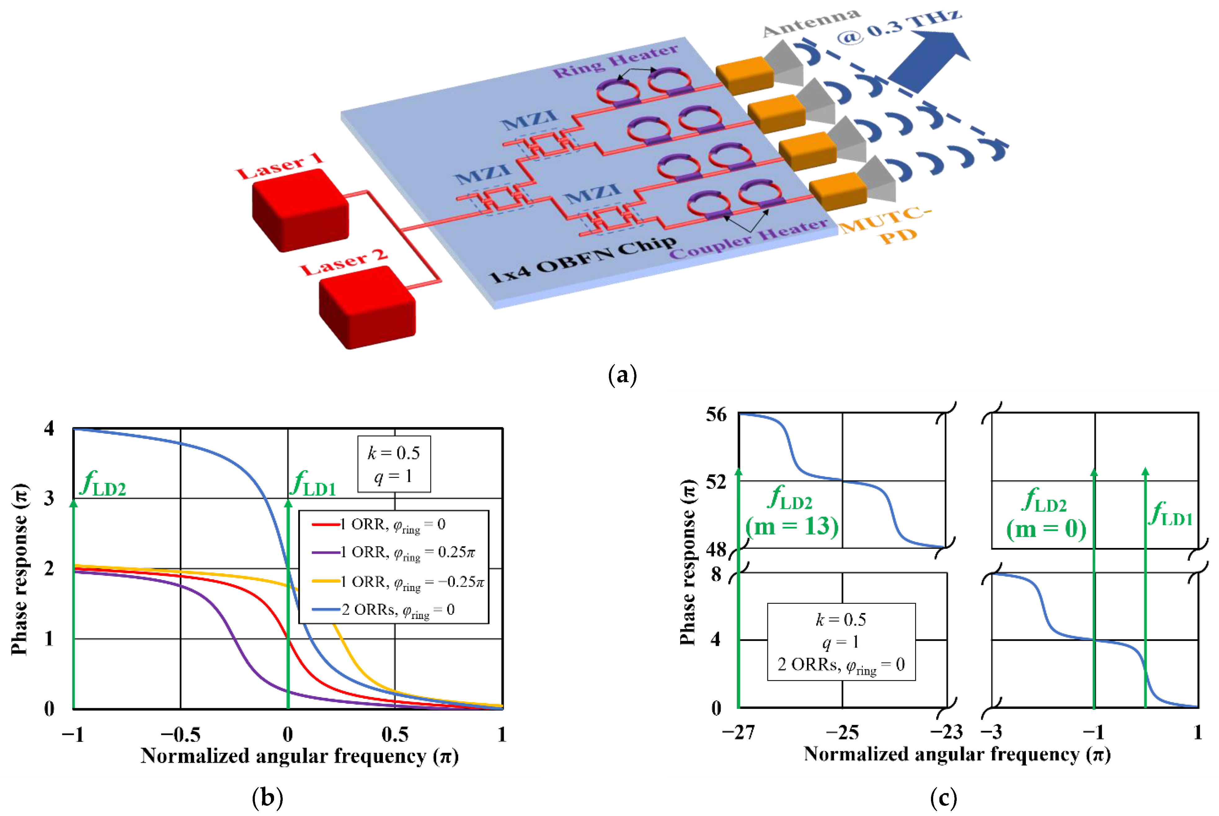
The concept of the 1 × 4 OBFN chip with integrated MUTC-PDs for 1D beam steering at 0.3 THz, based on optical heterodyning, is shown in
Figure 1a. The OBFN chip is designed and fabricated based on the Si
3N
4/SiO
2 TriPleX platform [
19], providing a low optical propagation loss, as well as a high optical confinement factor. Optical heterodyne laser signals (@1.55 µm) with a difference frequency of 0.3 THz, are combined and coupled into the OBFN chip. Three Mach–Zehnder interferometers (MZIs) are used as tunable optical splitters to adjust the power distribution into each waveguide, and to compensate for the non-uniform responsivity of the MUTC-PDs. Each OPS consists of two cascaded identical ORRs. The coupler heaters of the rings are used to change the power coupling coefficients, and thus to modify the slope of ORR’s phase response. By changing the biases of the ring heaters, the ORR’s resonance frequency offsets are shifted which allows it to modify the phase difference between the two optical heterodyne signals. Finally, MUTC-PDs are exploited to transfer the optical phase shift into the THz domain and by integrating the MUTC-PD array with antennas having a half-wavelength pitch, the THz beam direction can be controlled by the OBFN chip.
In detail, the phase response of a single ORR under the condition of over-coupling range can be calculated as follows [
20]:
where
Ω is the normalized angular frequency to the free spectral range (FSR) of the ORR (
Ω = 2∙
π∙f/
fFSR),
φring is the round-trip phase shift which indicates the resonance frequency offset of the ORR (
φring = 2∙
π∙fres,offset/
fFSR), and
k is the power coupling coefficient. The amplitude loss factor
q is a function of the round-trip loss
PL:
For a lossless ORR (
q = 1) with a power coupling coefficient of 0.5, the calculated phase response of a single ORR (
φring = 0) over one FSR (red line), is shown in
Figure 1b. As discussed before, the ORR is designed in such a way that one laser signal (
fLD1) is fixed at the ring’s resonance frequency, while the other heterodyne signal (
fLD2) is fixed at the off-resonance frequency. By changing
φring through the ring heater, the phase response can be shifted, as shown in
Figure 1b, by the purple and yellow lines. This allows it to impose different optical phase variations of the two laser signals, which are then transferred to the THz domain using the MUTC-PDs with Δ
φTHz = Δ
φLD1 − Δ
φLD2 [
21]. Since the maximum phase tunable range of the laser signal 1 (Δ
φLD1,max) is 2π when changing
φring from −π to π which synchronously leads to variations of
φLD2 (Δ
φLD2 ≠ 0), it is necessary to use two cascaded ORRs for each OPS (blue line in
Figure 1b) to achieve a THz phase shift Δ
φTHz of at least 2
π. It can also be observed from
Figure 1b that the FSR of the ORRs must be twice as large as the operating frequency, i.e., 0.6 THz, in order to fix one laser signal at resonance, and the one at off-resonance. The corresponding ORR round-trip length
L for an FSR of 0.6 THz should be 0.282 mm in the optimum case, which can be calculated using
where
ng is the group index of TriPleX waveguides and equal to 1.777. However, the minimum round-trip length of a fabricated ORR must be larger than 7 mm, due to the required heater length for thermo-optical control. This leads to a maximum FSR of 24.1 GHz, which is much smaller than the optimum value. However, thanks to the periodicity of ORRs, the condition
fLD2 at the off-resonance frequency and
fLD1 at the resonance frequency can be satisfied, if an FSR meets the following condition:
where
m is a natural number. As can be seen from
Figure 1c, the phase shift of laser signal with
fLD2 (m = 13) is equal to that with
fLD2 (m = 0). Consequently, all ORRs in this work are designed with an FSR of 22.22 GHz.
To eventually use the fabricated OBFN chip for beam steering, the thermo-optically controlled power coupling coefficient
k and the resonance frequency offset
fres,offset must be determined for each ORR, as a function of the coupler and ring heater voltages, respectively. To determine the power coupling coefficient, the group delay
τg is experimentally characterized using the wavelength-sweeping approach [
22] for coupler heater voltages from 4 V to 12 V. The power coupling coefficient
k can then be determined from the measured group delay using [
20]
For the fabricated OBFN chip, the measured optical propagation loss is ~0.7 dB/cm. By considering the round-trip length of 7.59 mm, the round-trip loss
PL can be calculated to be 0.5 dB. This leads to an amplitude loss factor
q of 0.944. The round-trip time
T can be calculated using
T = 1/
fFSR.
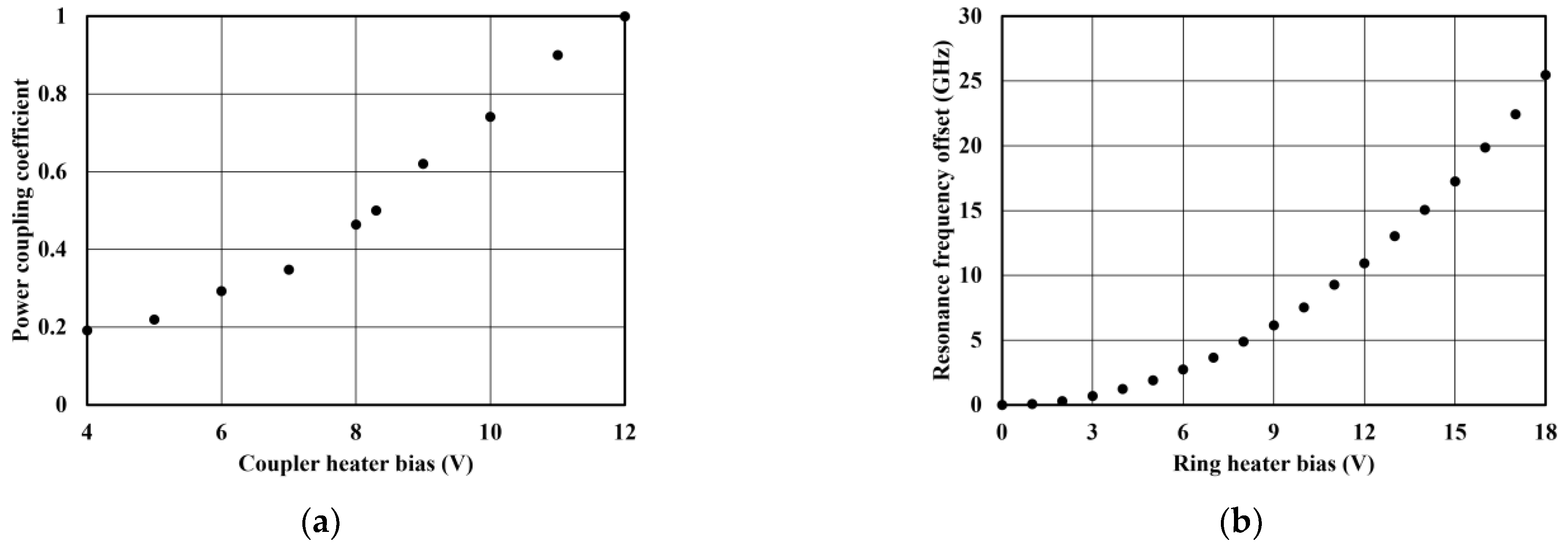
Figure 2a shows the measured power coupling coefficient
k as a function of the coupler heater bias. As can be seen, the power coupling coefficient increases from ~0.19 to ~1 by changing the bias voltage from 4 V to 12 V. Using a coupler heater bias of ~8.3 V, the power coupling coefficient can be set to 0.5.
The resonance frequency offsets of ORRs are determined experimentally using a high-resolution optical spectrum analyzer (OSA, AP2060A, APEX Technologies, Marcoussis, France).
Figure 2b shows the measured resonance frequency offset versus the ring heater bias. As can be seen, to shift the resonance frequency over one FSR, a bias voltage of ~17 V is required. For developing the control algorithm software, the measured resonance offset frequency is fitted using a sixth order polynomial equation
where
Ur is ring heater bias.
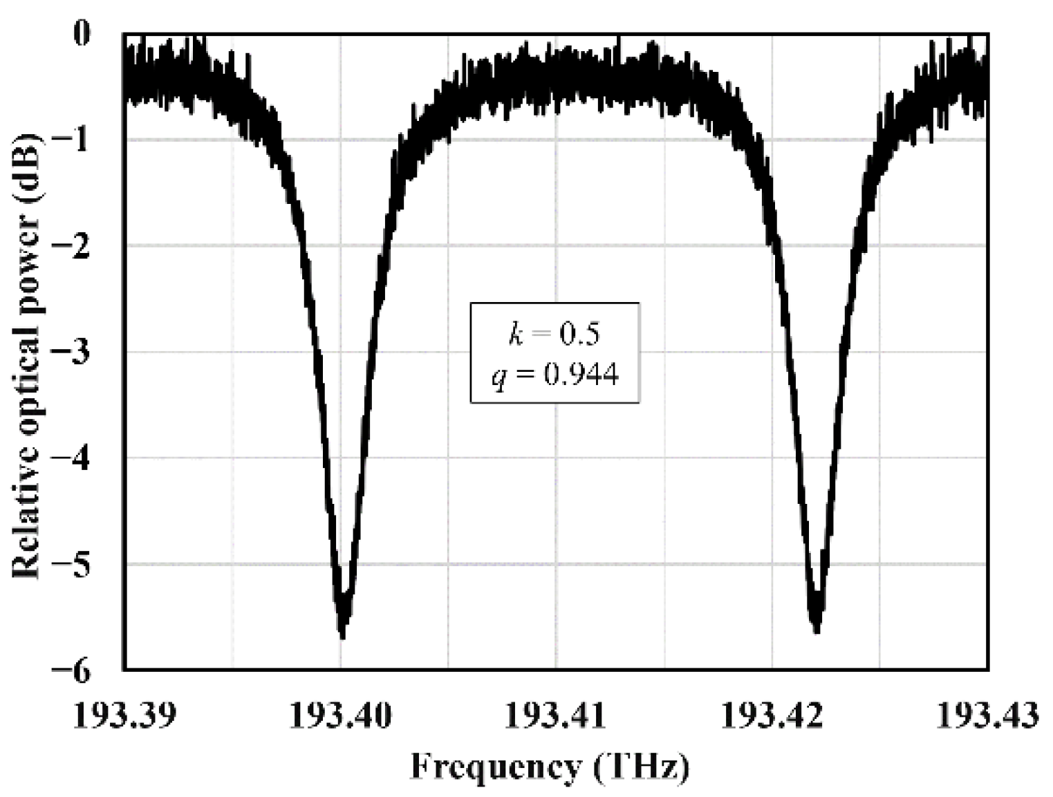
Based on the measurements, the power coupling coefficients of all ORRs are then set to 0.5 and the ring heaters are tuned to have the same resonance frequency in all ORRs. This is defined as the initial state for the OBFN chip, where the phase shifts of all OPSs are the same.
Figure 3 shows the optical frequency response of one OPS at the initial state. As can be seen, the two resonance frequencies are at 193.4001 THz and 193.4220 THz, indicating an FSR of ~21.9 GHz. Due to this slight deviation from the designed value of 22.22 GHz (<1.5%), the fabricated OBFN chip is ideally suited for 295.65 GHz, according to Equation (4).
3. Phase Shift Characterization
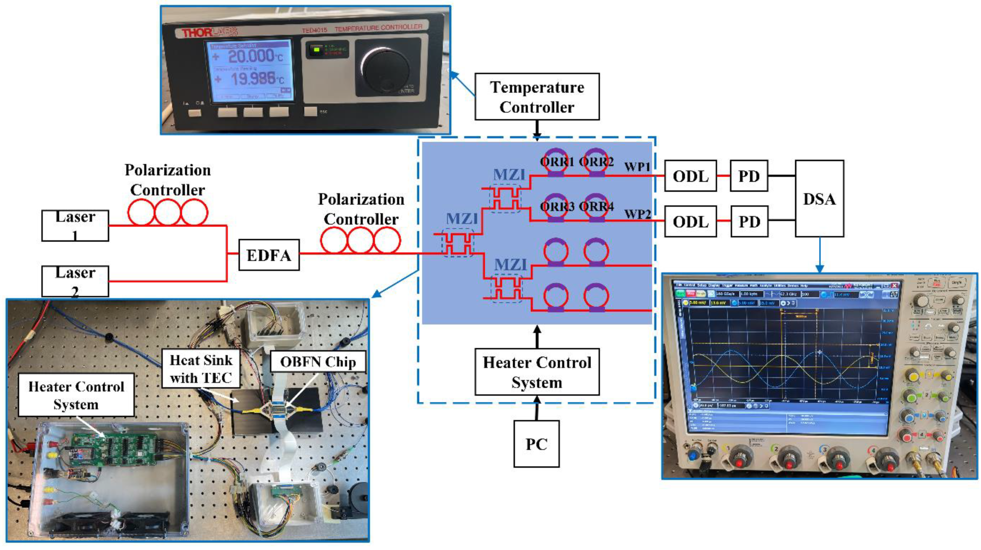
To measure the phase shift between two PDs when changing the biases of ring heaters of the fabricated OBFN chip, the measurement setup shown in
Figure 4 is used. Two optical heterodyne signals (@1.55 µm) are generated using two free running integrable tunable laser assemblies (PPCL200, Pure Photonics, San Jose, CA, USA). After amplification by an erbium-doped fiber amplifier (EDFA, EDFA100P, Thorlabs, Newton, NJ, USA), an optical polarization controller is used to ensure minimum optical losses due to the large polarization birefringence of TriPleX waveguides [
23]. A heater control system is developed and implemented to precisely regulate the bias of each on-chip heater. The OBFN chip is mounted on a heat sink with a thermo-electric cooler (TEC) regulated by a temperature controller (TED4015, Thorlabs, Dachau/Munich, Germany) at ~20 °C. To measure the phase difference between the two waveguide ports (WPs), two PDs are fiber-chip coupled to WP1 and WP2. Optical delay lines (ODLs, Newport, Irvine, CA, USA) are used to compensate for the fiber length difference between the two PDs and the OBFN chip. A digital signal analyzer (DSA, DSA-Z 634A, Keysight, Santa Rosa, CA, USA) is used to measure the amplitudes of the PD-generated RF signals in time domain.
Before experimental characterization, all ORRs are set to be in the initial state with a power coupling coefficient of 0.5 and a resonance frequency of 193.4001 THz, using the heater control system. Since the analog bandwidth of the DSA is limited to 63 GHz, the phase shift between the two WPs cannot be measured directly in the THz domain. However, thanks to the periodicity of the ORRs, it is still possible to measure the THz phase shift using lower microwave frequencies. As explained above, all frequencies
fLD1 and
fLD2 that fulfill Equation (4) experience the same phase shift. This means when fixing
fLD1 at 193.4001 THz (resonance frequency of the ORRs), the phase shift for
fLD2 = 193.41105 THz (with
m = 0) is same as for
fLD2 = 193.69575 THz (with
m = 13), as shown in
Figure 1c. Therefore, the resulting phase shift for an RF signal at 10.95 GHz, is the same as for an RF frequency at 295.65 GHz.
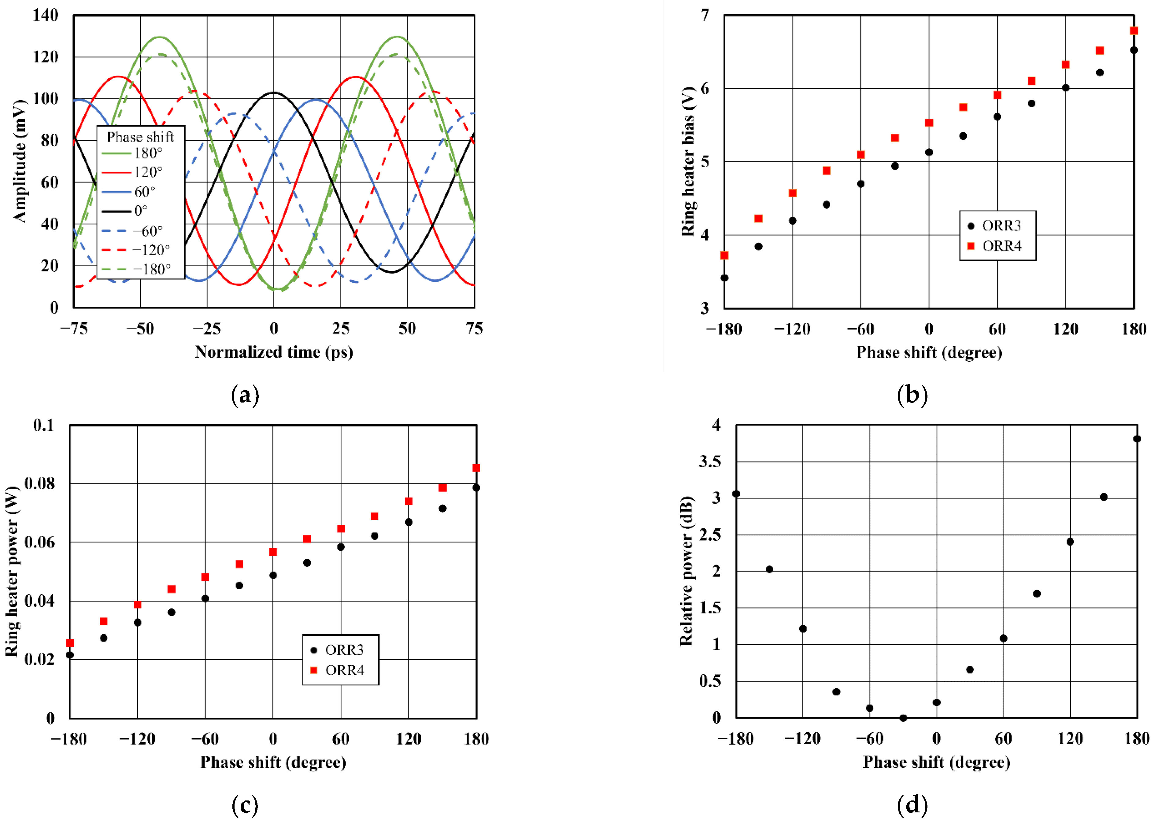
During the measurements at an RF frequency of 10.95 GHz, the signal generated by the PD at WP1 (see
Figure 4) is set as a trigger for the DSA, before tuning the two cascaded ORRs (ORR3 and ORR4) of the OPS for WP2. The RF signal measured this way is plotted in
Figure 5a. As can be observed, the time delay of the 10.95 GHz signal is successfully changed when tuning the ORRs. The amplitude with a peak at the normalized time of 0 ps (black solid line) corresponds to the initial state of the OBFN chip. By increasing the ring heater biases, the time delay of the measured RF signal at 10.95 GHz is tuned to ~15.2 ps (blue solid line), ~30.5 ps (red solid line) and ~45.7 ps (green solid line). This corresponds to phase shifts of ~60°, ~120° and ~180°, respectively. Inverse phase shifts down to −180° can be achieved by reducing the ring heater biases, as shown by the dashed lines. Therefore, in total, a phase tuning of 2
π is achieved. The corresponding ring heater bias settings are plotted in
Figure 5b. As can be seen, the ring heater biases of the two ORRs are slightly different due to fabrication tolerances. To achieve a 2π phase shift, the ring heater bias of the ORR3 is changed from 3.42 V to 6.52 V, while the bias of the ORR4 is increased from 3.72 V to 6.79 V. Using the measured heater resistance of 540 Ω, the dissipative powers of the two heaters are calculated and plotted in
Figure 5c. Consequently, a phase tuning efficiency of 0.058 W/
π is achieved.
From
Figure 5a, it can be also observed that the amplitudes of the 10.95 GHz signal vary for different phase shifts. This is because the dispersive power transmission loss of the ORRs causes a power variation when tuning the phase, especially for the laser signal at resonance frequency. As can be seen, the maximum amplitude deviation is ~40.15 mV when comparing the amplitudes of the RF signals with phase shifts of 180° and −60°. To systematically analyze the impact of this inherent power variation on THz beam steering performance of a 1 × 4 phased array, we measured the output power of a MUTC-PD (J-band photomixer module, NTT Electronics, Yokohama, Japan) at 0.295 THz for different phase shifts, using a zero-biased Schottky-barrier diode (SBD, WR3.4 ZBD, Virginia Diodes, Charlottesville, VA, USA) as power detector. The results are plotted in
Figure 5d. As can be seen, the minimum relative power is measured at a phase shift of −30° instead of 0°. This is traced back to the fact that the laser wavelength did not perfectly match the ORR’s resonance frequency during the experiments. For the full phase tuning range of 2π, the measured maximum THz output power variation is about 3.8 dB.
4. THz Beam Steering
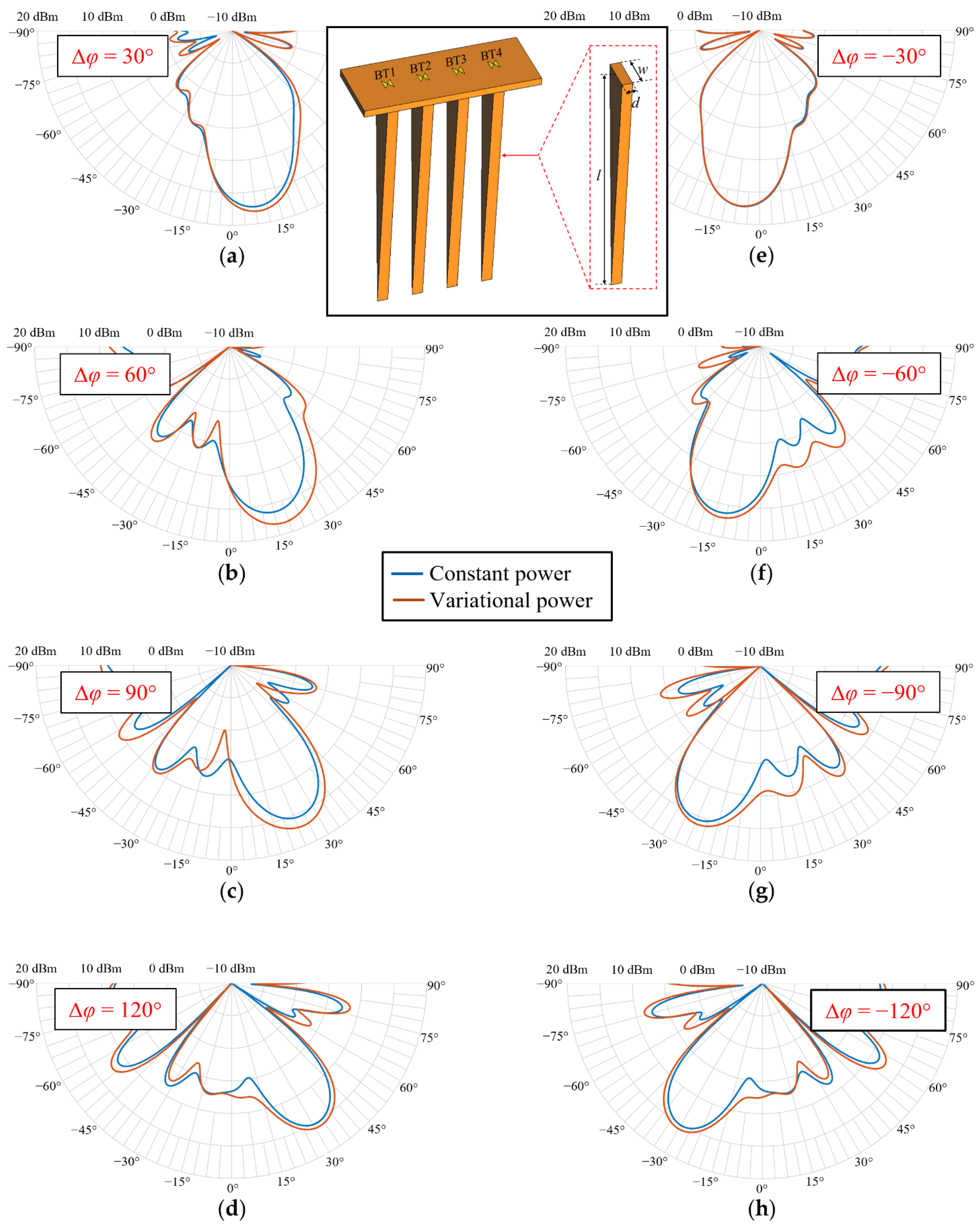
Using CST Studio Suite, we numerically analyze the impact of the measured THz power variation on the beam steering performance. This is done for a 1 × 4 phased array featuring four bow-tie (BT) antennas with a pitch of 500 µm placed on a 100 µm thick InP substrate. To increase the directivity of this approach, InP-based dielectric rod waveguide (DRW) antennas are placed underneath the BT antennas (see inset in
Figure 6). Each DRW antenna has a thickness
d of 150 µm and a length
l of 3500 µm. The width
w is 500 µm. To fix the DRW antennas in practice, they can be mounted using a low permittivity material such as ROHACELL [
24], glued on the backside of the InP substrate.
The beam steering behavior of the 1 × 4 array is investigated for two cases: (a) for a constant power at each BT antenna, and (b) when considering the measured power variations described in
Section 3. In both scenarios, the phase difference between two adjacent antennas Δ
φ is adjusted between −120° and 120°, with a step size of 30°. Phase differences larger than 120° would be possible using the fabricated OBFN, but would lead to substantially higher side lobs, and thus lower directivity and gain.
Table 1 summarizes the parameters for each of the four antennas used in the simulations. For the constant power scenario, all antennas have the same constant input power of 0.21 dBm, independent from the phase difference. This value is defined by the power level at the phase shift of 0° when the power level at −30° is assumed to be 0 dBm (see
Figure 5d). The phase of the BT1 maintains constant, and the phases of the other antennas are accordingly adjusted. For example, for a phase difference Δ
φ of 30°, the phases of BT1 to BT4 are set to be 0°, 30°, 60° and 90°. The corresponding polar diagrams of the absolute radiation power as a function of beam angle, which is the sum of the total input power of the four BT antennas in dBm and the simulated realized gain, are illustrated in
Figure 6a–h for all phase differences (blue lines). As can be seen, the beam angle is 31° for a phase difference between two adjacent antennas of 120°. The maximum absolute radiation power is always in excess of 15.2 dBm, independent of the phase difference. When using negative phase shifts, the beam turns to the inverse direction. The maximum beam steering angle that can be achieved is ~62°.
In the second scenario with varying antenna input powers, the simulated phase settings are the same as for the constant power scenario; only the input power for each antenna is set according to the measurement results, presented in
Figure 5d, when the power level at −30° is assumed to be 0 dBm as well. It needs to be mentioned that due to the phase periodicity, the power levels at negative phases (from 0° to −180°) can be used for powers at phases between 180° and 360°, e.g., the measured value at −120° is used for the power level at 240°. The power levels for phases between −180° and −360° are determined in the same manner. The resulting polar diagrams of the absolute radiation power (red lines) are presented in
Figure 6a–h as well. As can be seen, the radiation patterns, including the power variations, show a good agreement with those of where the power levels at each antenna are set to be constant. In general, the observed deviations of beam direction and maximum absolute radiation power are lower than 1° and 0.8 dB, respectively. Only for the phase differences of 60° and 90°, a larger power mismatch of <2 dB can be noticed, which is still reasonable. Thus, it is concluded that the inherent power variations when using the OBFN chip only have a minor impact on the steering performance of the phased array.
5. Discussion
In the last decade, thermo-optically controlled ORRs have been used to realize on-chip TTDs, supporting optical heterodyning for phased array at microwave frequencies to overcome the beam squint effect. For example, using two cascaded ORRs, the time delay is tunable up to 139.7 ps for a bandwidth of 8 GHz [
15]. In [
16], three ORRs are used in each delay unit for 41 GHz RF signals. A delay tuning range of 208.7 ps is demonstrated with a bandwidth of 6.3 GHz. In these two approaches, the time delay is managed by individually and diversely changing the power coupling coefficients of ORRs in each delay unit. Meanwhile, the resonance frequency of each ring must be adjusted synergistically and precisely to guarantee a reasonable ripple (within several picoseconds) for microwave frequencies. Another TTD for the 20 GHz band using a single ORR was demonstrated in [
17]. A delay tuning range of 26.6 ps is achieved by changing the coupler bias voltage from 12 V to 16 V, with a bandwidth of 5 GHz. Since MZIs are used as tunable couplers, delay adjustment will lead to the drift of the ORR resonance frequency which must be compensated using the ring heater voltage. The aforementioned approaches, regardless of the number of ORRs used for TTDs, require two additional ORRs for the phase shift adjustment of the optical heterodyne carrier; this compensates for the nonlinearity of the phase response of TTDs [
18], which further complicates the chip control, and increases the electrical power consumption.
In the THz domain, the beam angle becomes much more sensitive to time delay variations, as discussed in
Section 1. At 0.3 THz, the signal period is 3.33 ps and the beam direction can be steered of ~1°, with a time delay variation of only 30 fs. To achieve such high required delay tuning precisely, using ORR-based TTDs while keeping the ripple in the magnitude of femtoseconds, substantially more complex control circuitry is essential.
Due to the less dominant beam squint effect in the THz domain [
9], we developed the OPSs with two cascaded and identical ORRs in each, offering comparably simple control circuitry. Here, the coupler heater voltages are maintained constant after setting the power coupling coefficient of 0.5. A phase tuning range up to 2π is achieved by uniformly adjusting the resonance frequencies of two ORRs, without the complicated and synergistic handling needed for TTDs. Compared with the OPSs based on straight waveguides, with only one heater for each control unit [
10], the approach presented in this work demonstrates two inimitable merits. Firstly, the sharper phase response slope around resonance frequencies of ORRs, compared to that of straight waveguides, enables a higher phase tuning efficiency. In addition, the ORR-based OPSs are able to impose different optical phase variations on two combined optical heterodyne signals, due to the dispersive phase response of ORRs. Therefore, only one optical input is required for the OBFN chip, leading to a concise layout, as shown in
Figure 1a. In contrast to that, the OPSs based on straight waveguides can be used only for the phase tuning of one optical carrier. Other passive optical waveguides are necessary to combine the second optical heterodyne signal behind each OPS. Consequently, two optical inputs are necessary for the OBFN chip. This leads to inevitable waveguide intersections on the chip and higher optical loss, especially for large phased arrays.
The OBFN chip reported in this work can be further optimized by replacing the MZIs used in each ORR as tunable couplers by 3 dB directional couplers, since the power coupling coefficients of all ORRs maintain 0.5 during the phase tuning. This way, the footprint and the power consumption of the chip can be further reduced. In
Table 2, a summary of the OBFN chips discussed above is given.


