Article

Wavefront Correction in Vacuum of SULF-1PW Laser Beamline

1
State Key Laboratory of High Field Laser Physics and CAS Center for Excellence in Ultra-intense Laser Science, Shanghai Institute of Optics and Fine Mechanics, Chinese Academy of Sciences, Shanghai 201800, China
2
Institute of Optics and Electronics, Chinese Academy of Sciences, Chengdu 610200, China
*
Authors to whom correspondence should be addressed.
These authors contributed equally to this work.
Photonics 2022, 9(11), 872; https://doi.org/10.3390/photonics9110872
Submission received: 26 October 2022 / Revised: 11 November 2022 / Accepted: 16 November 2022 / Published: 18 November 2022
(This article belongs to the Special Issue Ultrashort Ultra-Intense (Petawatt) Laser)

Abstract

:
The focusing quality of high peak power lasers plays a crucial role in laser wakefield electron acceleration investigations. We report here an improvement in the focusing quality of the SULF-1PW laser beamline, planning to drive and generate 5~10 GeV electron beams. After the wavefront correction in vacuum with an adaptive optical system and the focusing with an f/56 off-axis parabolic mirror, near-diffraction-limited focal spots with a size of 52 × 54 μm2 at full width at half maximum are achieved, and the enclosed energy inside this size is ~36.6%. Consequently, the focused intensity of ~1.66 × 10¹⁹ W/cm2 can be achieved at 1 PW peak power. Moreover, we also examine the wavefront stability in air and vacuum, respectively. From the statistical analysis of 1900 shots of successive laser pulses at 1 Hz, we identify the wavefront fluctuation resulting from air turbulence and the better correction capacity in vacuum. This work demonstrates the importance and necessity of wavefront correction in vacuum for high peak power lasers.

1. Introduction

With the development of ultrashort, high peak power lasers based on the chirped pulse amplification (CPA) and optical parametric chirped pulse amplification (OPCPA) techniques [1,2], the strong field science has been a rapidly growing area in physics and meanwhile opened fascinating and entirely new applications. Among them, benefits from the high accelerating gradient (GeV/cm), laser wakefield accelerator has great potential for the development of compact accelerators and secondary radiation sources [3,4,5,6,7,8].
Laser wakefield electron acceleration is a highly nonlinear process based on the interaction of intense laser and gas targets. Hence, it can be significantly affected by the focused beam quality of driving lasers [9]. On the one hand, the focal spot size and the enclosed energy inside the focal spot decide the achievable laser intensity at targets. On the other hand, the focal depth determines the effective laser-matter interaction length, and the enclosed energy inside the focal spot is closely related to the charge of produced electron beams [10]. Hence, the improvement of focused beam quality plays an important role in the laser wakefield electron acceleration.
Wavefront aberrations are the main limitation to the realization of ideal focal spots and it can be divided into two categories: static aberration, resulting from the aberration of optical elements; and dynamic aberration, mostly originating from the thermal loading in the laser system [11]. The adaptive optical system (AOS) based on a deformable mirror (DM) is generally applied in high peak power lasers, in order to correct the wavefront aberration and therefore improve the focusing quality [12,13,14,15,16]. Sometimes, double AOSs with cascaded correction functions are also used, in view of the large beam size and serious aberration [17,18,19,20]. It is worth noting that the focused intensity exceeding 1023 W/cm2 has recently been achieved in CoReLS PW laser based on two-stage AOS and an f/1.1 off-axis parabolic (OAP) mirror [21].
For high peak power lasers, the wavefront correction in vacuum is greatly important and necessary. From air to vacuum, not only extra aberration may be introduced but also the air turbulence (one of the main sources of wavefront fluctuation [21,22]) can be quite different. The wavefront fluctuation will affect focal spot stability, which is crucial to achieving reproducible and consistent results in laser wakefield acceleration experiments and it will also influence the final correction result, since the more stable the wavefronts, the better the correction results to some extent.
In this work, we introduce an AOS after the laser compressor in our SULF-1PW laser beamline to improve its focusing quality, and then to drive and produce 5~10 GeV electron beams. After correction, the wavefront aberrations in root-mean-square (RMS) are around 0.09 μm and 0.06 μm, respectively, in air and vacuum cases. In vacuum, the focal spot size achieved by an f/56 OAP mirror is 52 μm × 54 μm at full width at half maximum (FWHM) which is close to the diffraction-limited value. The enclosed energy inside this size is about 36.6%, corresponding to a focused laser intensity of ~1.66 × 10¹⁹ W/cm2 in the case of 1 PW peak power. Furthermore, we also statistically analyze the wavefront fluctuation of 1900 consecutive laser shots at 1 Hz. The stand deviation (std) of RMS wavefront aberration fluctuation after correction is 0.01 μm and 0.005 μm in air and vacuum, respectively. These experimental results demonstrate that air turbulence should be one of the causes of wavefront fluctuation, and the wavefront correction in vacuum can realize better focusing quality. Hence, the wavefront correction in vacuum should be of great importance and necessity for laser wakefield electron acceleration.

2. Experimental Setup

The Shanghai Superintense Ultrafast Laser Facility (SULF) is a large-scale scientific project launched at 2016, including a repetition-rate 1 PW laser beamline (SULF-1PW) [23], an ultrahigh-peak-power 10 PW laser system [24], and three physical experimental platforms. Among them, the SULF-1PW laser beamline was finished at 2020 and has been in daily operation since then.
The SULF-1PW laser beamline supports 30 J/30 fs pulses output at 0.1 Hz, with a central wavelength of 800 nm and the beam diameter of ~215 mm. One of the important tasks of the SULF-1PW laser beamline is to drive laser wakefield acceleration. In order to produce 5~10 GeV electron beams by this laser beamline, an AOS utilizing a 230 mm-diameter DM is introduced after the laser compressor to improve the focusing quality. The DM is developed by the Institute of Optics and Electronics, CAS, based on piezoelectric technology. It owns 121 actuators that completely cover the laser beam and is coated with a broadband dielectric coating within the range from 750 nm to 850 nm. The coating is featured with high reflectivity and damage threshold, while its initial wavefront aberration is less than 0.01 μm in RMS. Furthermore, for measuring the wavefront aberration of this laser beamline and controlling the DM, a Hartmann wavefront sensor (WFS) with a 22 × 22 microlens array is installed. The experimental setup of wavefront correction is illustrated in Figure 1. The compressed laser beam is firstly reflected and delivered by a DM and then focused by an f/56 OAP mirror. The focused laser beam is extracted before the focus by inserting a partial reflection mirror (AM 1) and collimated by an achromatic OL (f = 200 mm). The collimated laser beam is up-collimated to 5.4 mm from 3.6 mm in diameter by a pair of achromatic doublets (f1 = 100 mm, f2 = 150 mm), and lastly sent into the WFS. The wavefront information measured by the WFS will be fed back to a closed-loop system connected with the DM, to compensate for the wavefront aberration at focus. The voltages of DM are optimized by iteratively closed-loop operation and finally fixed to the optimized value. As a result, a precise wavefront measurement and a proper wavefront correction can be performed with the WFS and the DM. In addition to the wavefront, the focal spot of this laser beamline can also be directly measured in this diagnostic setup.
In this setup, several points should be noted. Firstly, the AM 1–2 and the splitter have been detected by a Zygo interfero meter, the surface flatness of which is better than 0.02 μm (RMS), and the effective apertures of which are much larger than the beam size on them. In this case, the influence of surface flatness on wavefront aberration is negligible. Secondly, the OL and the relaying system in setup are both achromatic, within the spectral range of 750~850 nm. The achromatic lenses can minimize the wavefront aberration of this measurement setup. Thirdly, the DM is relay-imaged on the WFS. Because image relay is crucially important for the efficiency and stability of wavefront correction [25,26]. Fourthly, the window of the target chamber is carefully chosen. In the first place the transmitted wavefront aberration of the window itself should be small, to avoid introducing extra aberration. On this basis, for the same window, the wavefront aberrations of SULF-1PW laser beamline are measured in air and vacuum, respectively, without closed-loop correction. Only when the two results are consistent (i.e., the vacuum pressure-induced aberration in the window is slight), the corresponding window is adopted. The finally adopted window is made up of Corning 7980-0C glass, with the transmitted wavefront aberration of ~5 nm in RMS. Fifthly, an ideal point source (Fiber-coupled laser) running at 808 nm is set up rightly at the focus of OL, to accurately calibrate the extra aberrations introduced by this measurement setup. The map of measured aberration is taken as the new reference of the WFS. Lastly, the AM 1 is installed on a high-precision motorized LTP. In this way, the wavefront measurement and correction can be implemented at any time, even in the course of laser wakefield acceleration experiments.
In this work, the laser performance test is carried out under two modes (in air and in vacuum), and the laser condition is about 3 J/30 fs/1 Hz (i.e., ~100 TW/1 Hz) without pumping the final amplifier in SULF-1PW laser beamline. Though the extra thermal loading in the final amplifier and the laser compressor will also induce wavefront aberration, such an effect should be slight in our SULF-1PW laser beamline with the operation at 0.1 Hz. Furthermore, an additional energy attenuation module with high-quality partial reflection mirrors [23] is introduced after the final amplifier, which can significantly weaken the laser energy and hence avoid the intense laser-induced nonlinear effects in measurement.

3. Experimental Results

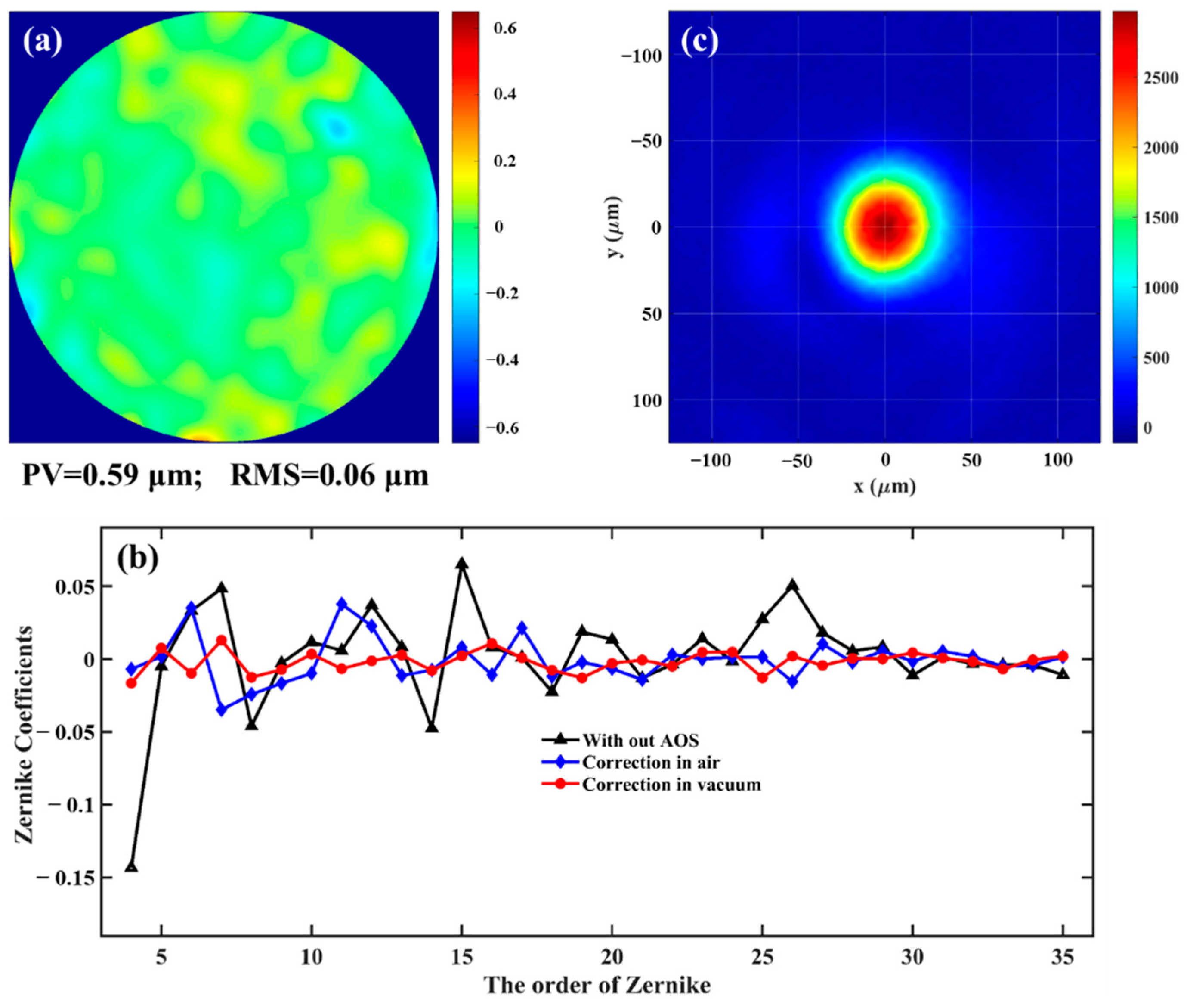
3.1. Without Wavefront Correction

In the previously mentioned laser wakefield electron acceleration experiments, there was no AOS in this laser beamline, the compressed pulse beams were directly focused by the f/56 OAP mirror. The peak-to-valley (PV) and RMS of wavefront aberration in this laser beamline are 1.27 μm and 0.20 μm, respectively, as shown in Figure 2a. Such a wavefront aberration is not devastating for this f/56 focusing system. Its focal spots are measured by a 12-bit CCD, as shown in Figure 2b. The focal spot size is 76 μm × 71 μm at FWHM, the encircled energy factor within this size is ~29.4%, and the focal depth is about 11 mm. Though the focal spot profile is acceptable, this size is much larger than the diffraction-limited, and some distinct speckles are around it. Under this focusing quality, quasi-mono-energetic electron beams around 2.7 GeV have been realized with 800 TW/0.1 Hz laser conditions. To obtain 5~10 GeV electron beams, an AOS will be installed after the laser compressor to improve the focusing quality.

3.2. Wavefront Correction in Air

The wavefront correction is first implemented in air, and the result measured with WFS after closed-loop correction is shown in Figure 3a. After correction, the PV and RMS of wavefront aberration are 0.77 μm and 0.09 μm, respectively. As shown in Figure 3b, the corrected focal spot size is 58 × 60 μm2 at FWHM, and the enclosed energy factor within this size is ~34.1%. Compared with the result in Section 3.1, this focal spot size is much smaller, and the enclosed energy factor is larger. That is to say, the focusing quality of SULF-1PW laser beamline is effectively improved after the wavefront correction in air. In the case of full peak power output (1 PW), the focused intensity will correspond to ~1.25 × 10¹⁹ W/cm2.

3.3. Wavefront Correction in Vacuum

Then, the wavefront correction of the SULF-1PW laser beamline is carried out in vacuum. From air to vacuum, the laser beamline is recalibrated based on some laser pointing (near- and far-field) monitoring and electric adjusting systems. As Figure 4a shows, an almost flat wavefront is obtained after the closed-loop correction in vacuum. The PV and RMS of the corrected wavefront aberration are 0.59 μm and 0.06 μm, respectively. This small amount of residual wavefront aberration is probably induced by the spatio-temporal coupling in the laser compressor [27,28]. It is worth noting that the final correction results in vacuum is better than that in air, which is possibly because the air turbulence in the compressor and chambers is eliminated in vacuum, and hence, the wavefront is more stable and a better correction result can be achieved in the case of a more stable wavefront. The measured wavefront fluctuations in air and vacuum will be presented in the following Section 3.4.
The first 35 orders of Zernike coefficients of the measured wavefronts before and after correction are shown in Figure 4b. We find that the aberrations in this laser beamline (black triangles) are mainly low-order components, especially the 0°-astigmatism (Z4). After the correction in air (blue rhombus), the large-scale aberrations are effectively compensated. After the correction in vacuum (red circles), the low-order aberrations are further compensated, and the small-scale high-order aberrations are corrected to nearly zero.
After the wavefront correction in vacuum, the focal spots are also measured, shown in Figure 4c. The focal spot size at FWHM is 52 × 54 μm2, which is close to the diffraction-limited. Figure 5 shows the cross-sectional profile and the encircle energy cure of the measured focal spot. The enclosed energy factor is ~36.6% within FWHM, corresponding to a focused intensity of ~1.66 × 10¹⁹ W/cm2 in the case of 1 PW peak power output. Compared with the focal spots in Section 3.1 and Section 3.2, the focused intensity after wavefront correction in vacuum can be improved by ~2.4 and ~1.33 times, respectively, under the same laser peak power. Furthermore, the measured focal depth after wavefront correction in vacuum is around 20 mm, which is about 1.8 times that without AOS. Such a long focal depth is favorable for laser wakefield electron acceleration. At present, remarkable progress has been made in electron energy in the laser wakefield acceleration experiment, based on our SULF-1PW laser beamline after the wavefront correction in vacuum. Detailed information will be reported by our physical research group in the future.

3.4. Wavefront Stability

The wavefront fluctuation can affect the focal spot stability and the final correction result, which are both crucial in laser wakefield electron acceleration experiments. Hence, the wavefront stability of the SULF-1PW laser beamline is examined and statistically analyzed. The fluctuation of RMS wavefront aberration (ΦRMS) of 1900 successive laser shots operating at 1 Hz after the closed-loop correction is shown in Figure 6. In air, the average and the std values of ΦRMS are 0.09 μm and 0.01 μm, respectively. In vacuum, the average and the std values are down to 0.06 μm and 0.005 μm, respectively. This measurement results show that the wavefront stability in air is worse than that in vacuum, which is mainly due to the air turbulence in the laser compressor and target chambers. In turn, it is exactly because of the more stable wavefront, the final correction result in vacuum can be better than that in air to some extent. Hence, we can know that the wavefront correction in vacuum is very meaningful for high-peak power lasers.

4. Conclusions

In conclusion, we improve the focusing quality of the SULF-1PW laser beamline, by correcting its wavefront with a 230 mm-diameter DM located after the laser compressor. After the closed-loop correction in vacuum, the RMS wavefront aberration is only 0.06 μm, and near diffraction-limited focal spots are achieved. The focal spot size at FWHM is 52 × 54 μm2, and the enclosed energy inside this size is about 36.6%, corresponding to a focused intensity of ~1.66 × 10¹⁹ W/cm2 at 1 PW peak power. With respect to the focusing without AOS, the focused intensity is improved by ~2.4 times and the focal depth is lengthened by ~1.8 times. Moreover, we also confirm that the wavefront fluctuation induced by the air turbulence in the laser compressor and chambers can degrade the final correction results. As a result, the wavefront correction in vacuum should be of great importance and necessity. In the following work, an f/2 OAP mirror will also be applied to focus the 1PW laser beam for proton acceleration investigation, and the corresponding laser intensity is promising to exceed 1022 W/cm2.

Author Contributions

Conceptualization, F.W. and Y.L.; methodology, Z.Z., Y.X. and Z.Y.; formal analysis, E.L.; investigation, F.W., E.L., Z.Z., J.Q., J.Z., J.H., Y.Z. and P.B.; writing—original draft preparation, F.W.; writing—review and editing, E.L., Y.X. and Y.L. All authors participated in the general discussion of obtained results. All authors have read and agreed to the published version of the manuscript.

Funding

This research was funded by National Natural Science Foundation of China (61925507), National Key R&D Program of China (2017YFE0123700, 2019YFF01014401), Strategic Priority Research Program of Chinese Academic Science (XDB1603), Shanghai Natural Science Foundation (20ZR1464600), Shanghai Municipal Science and Technology Major Project (2017SHZDZX02), Program of Shanghai Academic/Technology Research Leader (18XD1404200), Shanghai Sailing Program (21YF1453800).

Institutional Review Board Statement

Not applicable.

Informed Consent Statement

Not applicable.

Data Availability Statement

Data underlying the results presented in this paper are not publicly available at this time but may be obtained from the authors upon request.

Conflicts of Interest

The authors declare no conflict of interest.

References

  1. Strickland, D.; Mourou, G. Compression of amplified chirped optical pulses. Opt. Commun. 1985, 55, 219–221. [Google Scholar] [CrossRef]
  2. Dubietis, A.; Jonušauskas, G.; Piskarskas, A. Powerful femtosecond pulse generation by chirped and stretched pulse parametric amplification in BBO crystal. Opt. Commun. 1992, 88, 437–440. [Google Scholar] [CrossRef]
  3. Laso Garcia, A.; Höppner, H.; Pelka, A.; Bähtz, C.; Brambrink, E.; Di Dio Cafiso, S.; Dreyer, J.; Göde, S.; Hassan, M.; Kluge, T.; et al. ReLaX: The Helmholtz International Beamline for Extreme Fields high-intensity short-pulse laser driver for relativistic laser–matter interaction and strong-field science using the high energy density instrument at the European X-ray free electron laser facility. High Power Laser Sci. Eng. 2021, 9, e59. [Google Scholar]
  4. Zhang, H.; Zhao, J.; Hu, Y.; Li, Q.; Lu, Y.; Cao, Y.; Zou, D.; Sheng, Z.; Pegoraro, F.; McKenna, P.; et al. Efficient bright γ-ray vortex emission from a laser-illuminated light-fan-in-channel target. High Power Laser Sci. Eng. 2021, 9, e43. [Google Scholar] [CrossRef]
  5. Cinquegrana, P.; Demidovich, A.; Kurdi, G.; Nikolov, I.; Sigalotti, P.; Susnjar, P.; Danailov, M. The seed laser system of the FERMI free-electron laser: Design, performance and near future upgrades. High Power Laser Sci. Eng. 2021, 9, e61. [Google Scholar] [CrossRef]
  6. Emma, C.; Van Tilborg, J.; Assmann, R.; Barber, S.; Cianchi, A.; Corde, S.; Couprie, M.E.; D’Arcy, R.; Ferrario, M.; Habib, A.F.; et al. Free electron lasers driven by plasma accelerators: Status and near-term prospects. High Power Laser Sci. Eng. 2021, 9, e57. [Google Scholar] [CrossRef]
  7. Gonsalves, A.J.; Nakamura, K.; Daniels, J.; Benedetti, C.; Pieronek, C.; de Raadt, T.C.H.; Steinke, S.; Bin, J.H.; Bulanov, S.S.; van Tilborg, J.; et al. Petawatt laser guiding and electron beam acceleration to 8GeV in a laser-heated capillary discharge waveguide. Phys. Rev. Lett. 2019, 122, 084801. [Google Scholar] [CrossRef] [PubMed] [Green Version]
  8. Wang, W.; Feng, K.; Ke, L.; Yu, C.; Xu, Y.; Qi, R.; Chen, Y.; Qin, Z.; Zhang, Z.; Fang, M.; et al. Free-electron lasing at 27 nanometres based on a laser wakefield accelerator. Nature 2020, 595, 516. [Google Scholar] [CrossRef]
  9. Wang, X.; Zgadzaj, R.; Fazel, N.; Li, Z.; Yi, S.A.; Zhang, X.; Henderson, W.; Chang, Y.Y.; Korzekwa, R.; Tsai, H.E.; et al. Quasi-monoenergetic laser-plasma acceleration of electrons to 2 GeV. Nat. Commun. 2013, 4, 1988. [Google Scholar] [CrossRef] [Green Version]
  10. Esarey, E.; Schroeder, C.B.; Leemans, W.P. Physics of laser-driven plasma-based electron accelerators. Rev. Mod. Phys. 2009, 81, 1229. [Google Scholar] [CrossRef]
  11. Miranda, M.; Kotur, M.; Rudawski, P.; Guo, C.; Harth, A.; L’Huillier, A.; Arnold, C.L. Spatiotemporal characterization of ultrashort laser pulses using spatially resolved Fourier transform spectrometry. Opt. Lett. 2014, 39, 5142–5145. [Google Scholar] [CrossRef] [PubMed]
  12. Isono, F.; van Tilborg, J.; Barber, S.K.; Natal, J.; Berger, C.; Tsai, H.E.; Ostermayr, T.; Gonsalves, A.; Geddes, C.; Esarey, E. High-power non-perturbative laser delivery diagnostics at the final focus of 100-TW-class laser pulses. High Power Laser Sci. Eng. 2021, 9, e25. [Google Scholar] [CrossRef]
  13. Borneis, S.; Laštovička, T.; Sokol, M.; Jeong, T.-M.; Condamine, F.; Renner, O.; Tikhonchuk, V.; Bohlin, H.; Fajstavr, A.; Hernandez, J.-C.; et al. Design, installation and commissioning of the ELI-Beamlines high-power, high-repetition rate HAPLS laser beam transport system to P3. High Power Laser Sci. Eng. 2021, 9, e30. [Google Scholar] [CrossRef]
  14. Rajaeipour, P.; Banerjee, K.; Dorn, A.; Zappe, H.; Ataman, C. Cascading optofluidic phase modulators for performance enhancement in refractive adaptive optics. Adv. Photonics 2020, 2, 066005. [Google Scholar] [CrossRef]
  15. Lureau, F.; Matras, G.; Chalus, O.; Derycke, C.; Morbieu, T.; Radier, C.; Casagrande, O.; Laux, S.; Ricaud, S.; Rey, G.; et al. High-energy hybrid femtosecond laser system demonstrating 2 × 10 PW capability. High Power Laser Sci. Eng. 2020, 8, e43. [Google Scholar] [CrossRef]
  16. Wang, D.; Zhang, X.; Dai, W.; Yang, Y.; Deng, X.; Chen, L.; Xie, X.; Hu, D.; Jing, F.; Yang, Z.; et al. 1178 J, 527 nm near diffraction limited laser based on a complete closed-loop adaptive optics controlled off-axis multi-pass amplification laser system. High Power Laser Sci. Eng. 2021, 9, e22. [Google Scholar] [CrossRef]
  17. Sung, J.H.; Lee, H.W.; Yoo, J.Y.; Yoon, J.W.; Lee, C.W.; Yang, J.M.; Son, Y.J.; Jang, Y.H.; Lee, S.K.; Nam, C.H. 4.2 PW, 20 fs Ti:sapphire laser at 0.1 Hz. Opt. Lett. 2017, 42, 2058–2061. [Google Scholar] [CrossRef]
  18. Baumhacker, H.; Pretzler, G.; Witte, K.J.; Hegelich, M.; Kaluza, M.; Karsch, S.; Kudryashov, A.; Samarkin, V.; Roukossouev, A. Correction of strong phase and amplitude modulations by two deformable mirrors in a multistaged Ti:sapphire laser. Opt. Lett. 2002, 27, 1570–1572. [Google Scholar] [CrossRef]
  19. Guo, Z.; Yu, L.; Wang, J.; Wang, C.; Liu, Y.; Gan, Z.; Li, W.; Leng, Y.; Liang, X.; Li, R. Improvement of the focusing ability by double deformable mirrors for 10-PW-level Ti:sapphire chirped pulse amplification laser system. Opt. Express 2018, 26, 341982. [Google Scholar] [CrossRef]
  20. Yoon, J.W.; Jeon, C.; Shin, J.; Lee, S.K.; Lee, H.W.; Choi, I.W.; Kim, H.T.; Sung, J.H.; Nam, C.H. Achieving the laser intensity of 5.5 × 10²² W/cm2 with a wavefront-corrected multi-PW laser. Opt. Express 2019, 27, 20412–20420. [Google Scholar] [CrossRef]
  21. Yoon, J.W.; Kim, Y.G.; Choi, I.W.; Sung, J.H.; Lee, H.W.; Lee, S.K.; Nam, C.H. Realization of laser intensity over 1023 W/cm2. Optica 2021, 8, 630–635. [Google Scholar] [CrossRef]
  22. Chen, M.; Jin, X.; Li, S.; Xu, Z. Compensation of turbulence-induced wavefront aberration with convolutional neural networks for FSO systems. Chin. Opt. Lett. 2021, 19, 110601. [Google Scholar] [CrossRef]
  23. Zhang, Z.; Wu, F.; Hu, J.; Yang, X.; Gui, J.; Liu, X.; Wang, C.; Liu, Y.; Lu, X.; Xu, Y.; et al. The 1 PW/0.1 Hz laser beamline in SULF facility. High Power Laser Sci. Eng. 2020, 8, e4. [Google Scholar] [CrossRef] [Green Version]
  24. Gan, Z.; Yu, L.; Wang, C.; Liu, Y.; Xu, Y.; Li, W.; Li, S.; Yu, L.; Wang, X.; Liu, X.; et al. The Shanghai superintense ultrafast laser facility (SULF) project. In Progress in Ultrafast Intense Laser Science XVI; Springer International Publishing: Cham, Switzerland, 2021; p. 199. [Google Scholar]
  25. Planchon, T.A.; Rousseau, J.P.; Burgy, F.; Cheriaux, G.; Chambaret, J.P. Adaptive wavefront correction on a 100-TW/10-Hz chirped pulse amplification laser and effect of residual wavefront on beam propagation. Opt. Commun. 2005, 252, 222–228. [Google Scholar] [CrossRef]
  26. Planchon, T.A.; Mercère, P.; Cheriaux, G.; Chambaret, J.P. Off-axis aberration compensation of focusing with spherical mirrors using deformable mirrors. Opt. Commun. 2003, 216, 25–31. [Google Scholar] [CrossRef]
  27. Kahaly, S.; Monchocé, S.; Gallet, V.; Gobert, O.; Réau, F.; Tcherbakoff, O.; D’Oliveira, P.; Martin, P.; Quéré, F. Investigation of amplitude spatio-temporal couplings at the focus of a 100 TW-25 fs laser. Appl. Phys. Lett. 2014, 104, 054103. [Google Scholar] [CrossRef] [Green Version]
  28. Li, Z.; Tsubakimoto, K.; Yoshida, H.; Nakata, Y.; Miyanaga, N. Degradation of femtosecond petawatt laser beams: Spatio-temporal/spectral coupling induced by wavefront errors of compression gratings. Appl. Phys. Express 2017, 10, 102702. [Google Scholar] [CrossRef]
Figure 1. Experimental setup of SULF-1PW laser beamline. AM 1–2, partial reflection mirrors; LTP, Linear translation platform; W, Window; OL, objective lens; WFS, Hartmann wavefront sensor.
Photonics 09 00872 g001
Figure 2. Measured (a) wavefront and (b) focal spot of SULF-1PW laser beamline without AOS.
Photonics 09 00872 g002
Figure 3. (a) The wavefront map measured at WFS (b) the focal spot image measured by CCD, after AOS closed-loop operation in air.
Photonics 09 00872 g003
Figure 4. (a) The wavefront map measured at WFS after AOS closed-loop operation in vacuum; (b) the Zernike coefficients of the wavefront maps before and after correction; (c) the focal spot image measured by CCD after AOS closed-loop operation in vacuum.
Photonics 09 00872 g004
Figure 5. The (a) cross-sectional profiles of the focal spot after wavefront correction in vacuum, and the (b) encircled energy factor with and without wavefront correction in vacuum.
Photonics 09 00872 g005
Figure 6. The fluctuation of RMS wavefront aberration of 1900 shots successive laser pulse operating at 1 Hz (a) in air and (b) in vacuum.
Photonics 09 00872 g006
Publisher’s Note: MDPI stays neutral with regard to jurisdictional claims in published maps and institutional affiliations.

