Generation, Transmission, and Amplification of OAM Modes in the PbSe-Doped Ring-Core Fiber Carrying 3D Printed Spiral Phase Plate

 ,
,
Abstract
:1. Introduction
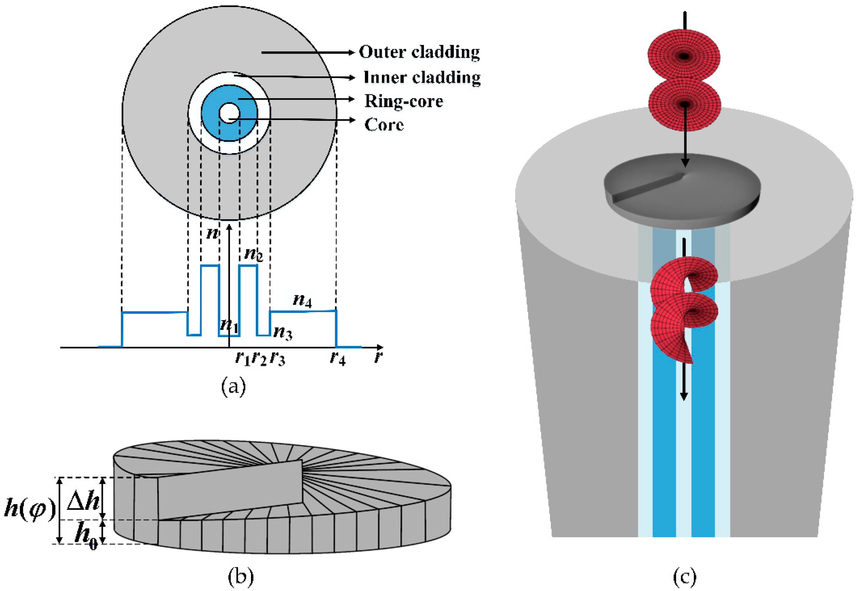
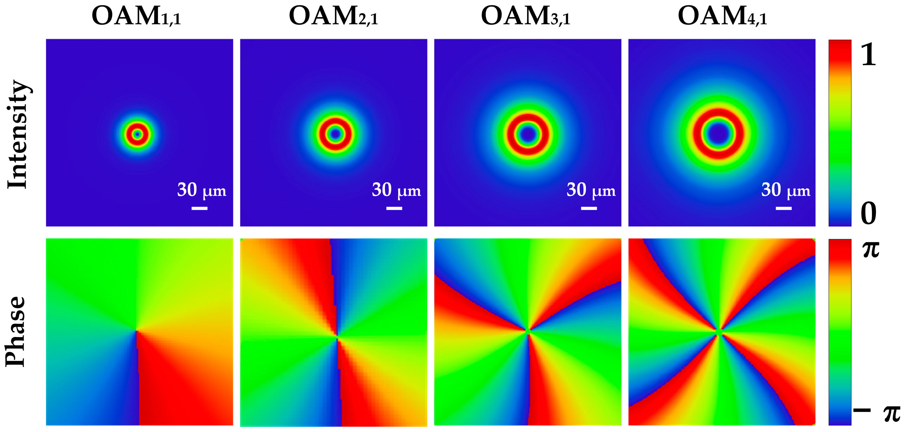
2. Design and Simulations
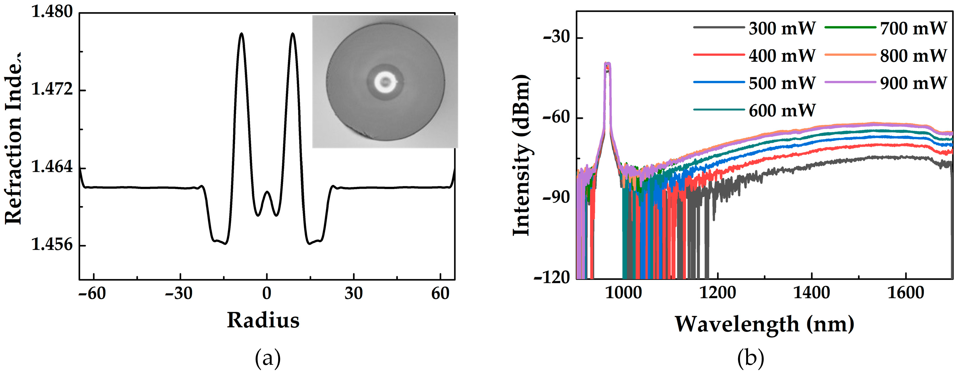
3. Fabrication
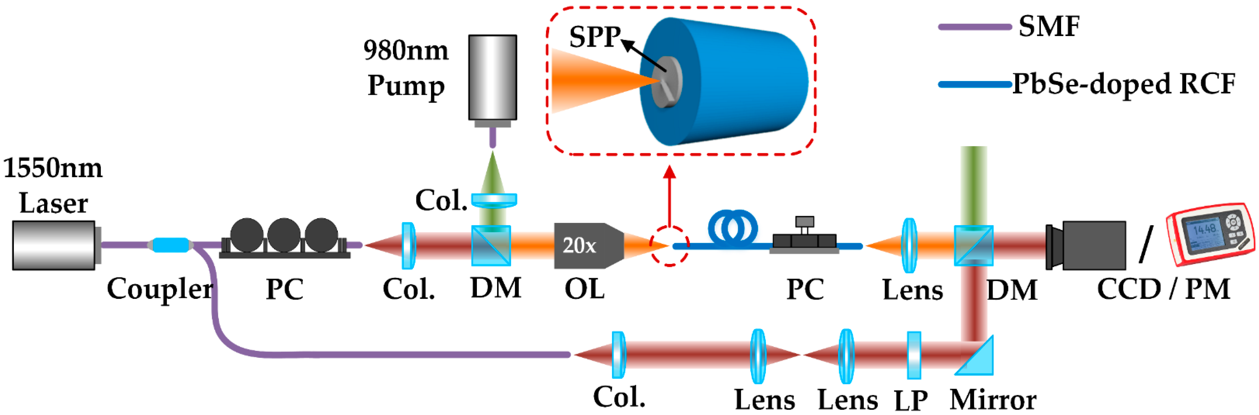
4. Experiments
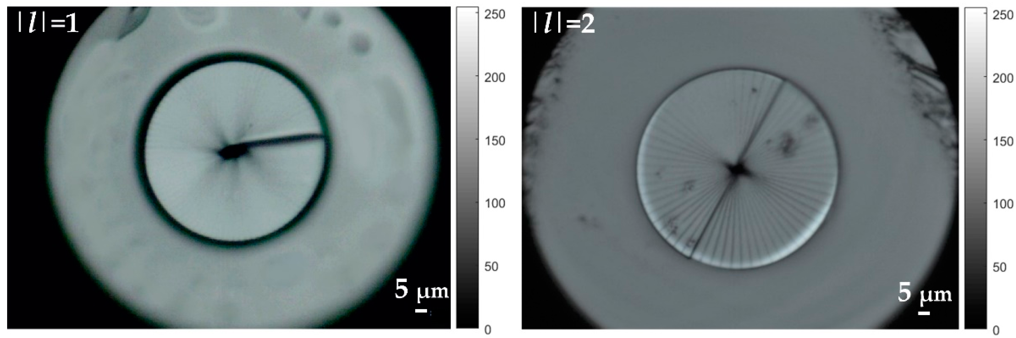
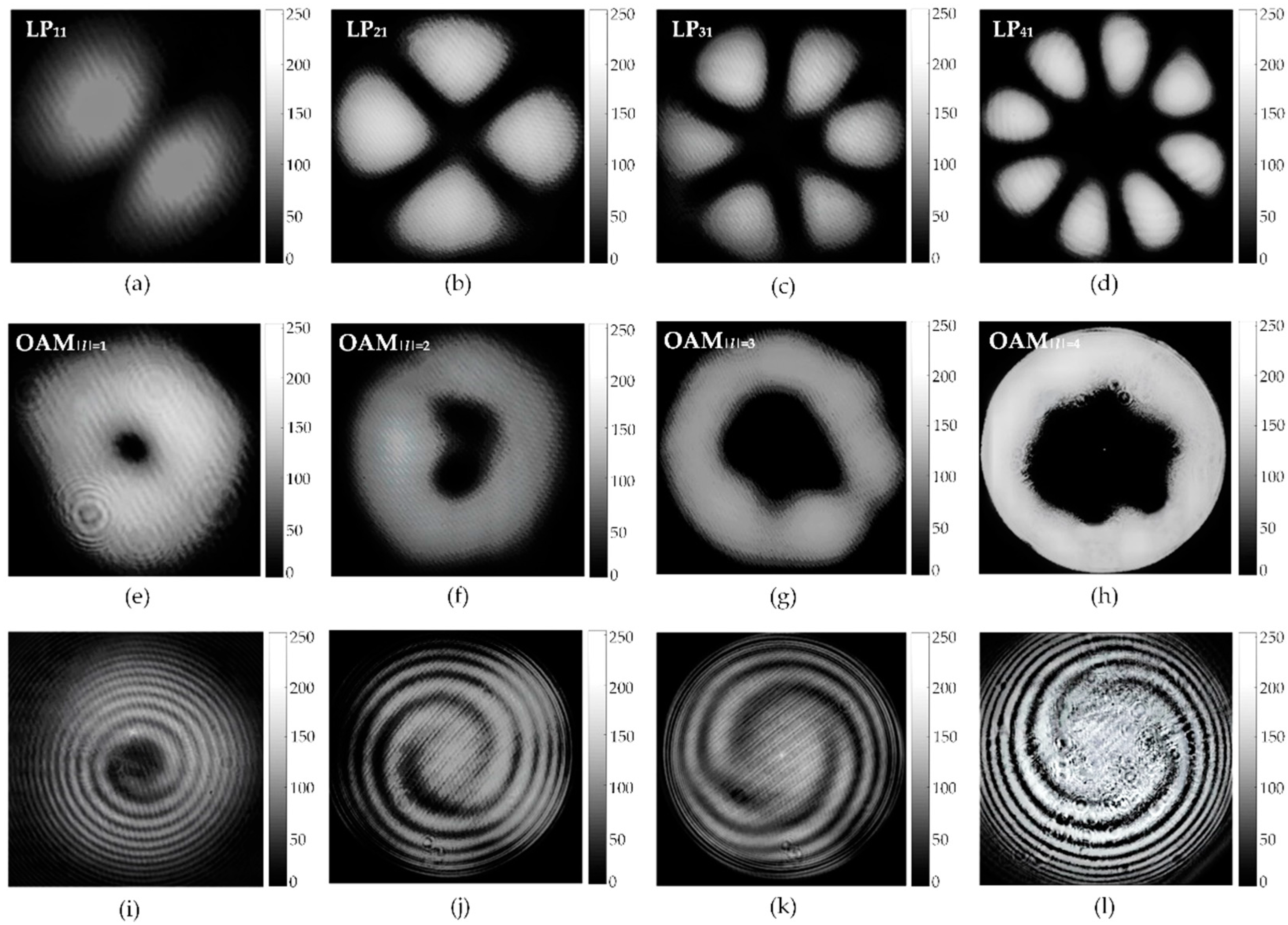
4.1. Generation and Transmission of OAM Modes
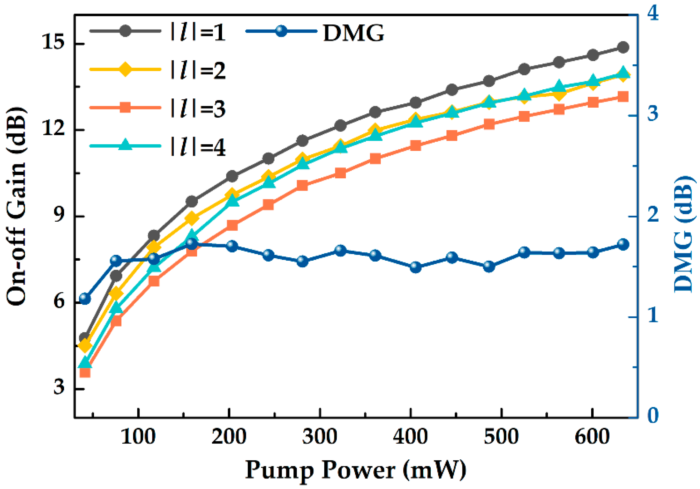
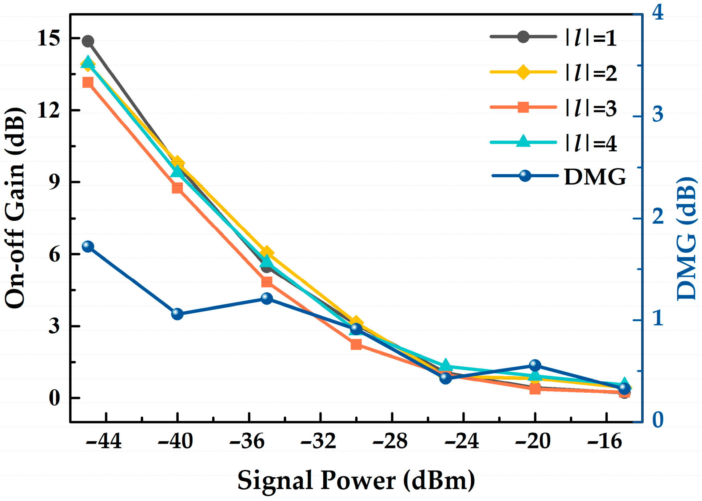
4.2. Amplificaition of OAM Modes
5. Conclusions
Author Contributions
Funding
Institutional Review Board Statement
Informed Consent Statement
Data Availability Statement
Conflicts of Interest
References
- Willner, A.E.; Huang, H.; Yan, Y.; Ren, Y.; Ahmed, N.; Xie, G.; Bao, C.; Li, L.; Cao, Y.; Zhao, Z.; et al. Optical communications using orbital angular momentum beams. Adv. Opt. Photonics 2015, 7, 66–106. [Google Scholar] [CrossRef] [Green Version]
- Cheng, W.; Zhang, W.; Jing, H.; Gao, S.; Zhang, H. Orbital angular momentum for wireless communications. IEEE Wirel. Commun. 2018, 26, 100–107. [Google Scholar] [CrossRef] [Green Version]
- Pang, F.; Xiang, L.; Liu, H.; Zhang, L.; Wen, J.; Zeng, X.; Wang, T. Review on fiber-optic vortices and their sensing applications. J. Lightwave Technol. 2021, 39, 3740–3750. [Google Scholar] [CrossRef]
- Geday, M.A.; Caño-García, M.; Otón, J.M.; Quintana, X. Adaptive spiral diffractive lenses—Lenses with a twist. Adv. Opt. Mater. 2020, 8, 2001199. [Google Scholar] [CrossRef]
- Zhang, Y.; Wang, J.; Qian, X.; Zhu, W.; Li, J. Orbital angular momentum evolution of twisted multi-Gaussian Schell model beams in anisotropic turbulence. Opt. Commun. 2022, 520, 128454. [Google Scholar] [CrossRef]
- Jung, Y.; Alam, S.U.; Richardson, D.J.; Ramachandran, S.; Abedin, K.S. Multicore and multimode optical amplifiers for space division multiplexing. In Optical Fiber Telecommunications VII; Willner, A.E., Ed.; Academic Press: New York, NY, USA, 2020; pp. 301–333. [Google Scholar] [CrossRef]
- Bai, Y.; Lv, H.; Fu, X.; Yang, Y. Vortex beam: Generation and detection of orbital angular momentum. Chin. Opt. Lett. 2022, 20, 012601. [Google Scholar] [CrossRef]
- Yang, D.; Lin, J.; Chen, C.; Li, C.; Hao, J.; Lv, B.; Zhou, K.; Wang, Y.; Jin, P. Multiwavelength high-order optical vortex detection and demultiplexing coding using a metasurface. Adv. Photonics Nexus 2022, 1, 016005. [Google Scholar] [CrossRef]
- Krenn, M.; Handsteiner, J.; Fink, M.; Fickler, R.; Ursin, R.; Malik, M.; Zeilinger, A. Twisted light transmission over 143 km. Proc. Natl. Acad. Sci. USA 2016, 113, 13648–13653. [Google Scholar] [CrossRef] [Green Version]
- Zhang, X.; Liu, J.; Chen, S.; Li, W.; Du, C.; Wang, J. Amplification of 14 orbital angular momentum modes in ring-core erbium-doped fiber with high modal gain. Opt. Lett. 2021, 46, 5647–5650. [Google Scholar] [CrossRef]
- Mehta, A.; Rehan, M.; Rastogi, V. Erbium-doped circular photonic crystal fiber design for the amplification of 20 OAM modes. J. Opt. Soc. Am. B 2021, 38, F138–F144. [Google Scholar] [CrossRef]
- Wen, T.; Gao, S.; Li, W.; Tu, J.; Du, C.; Zhou, J.; Ao, Z.; Zhang, B.; Liu, W.; Li, Z. Third-and fourth-order orbital angular momentum multiplexed amplification with ultra-low differential mode gain. Opt. Lett. 2021, 46, 5473–5476. [Google Scholar] [CrossRef] [PubMed]
- Liu, S.; Zhang, L.; Jiang, Q.; Xue, X.; Wen, J.; Chen, W.; Pang, F.; Wang, T. The Performance of Orbital Angular Momentum Mode (|l| = 1~3) Amplification Based on Ring-Core Erbium-Doped Fibers. Photonics 2022, 9, 491. [Google Scholar] [CrossRef]
- Caño-García, M.; Quintana, X.; Otón, J.M.; Geda, M.A. Dynamic multilevel spiral phase plate generator. Sci. Rep. 2018, 8, 15804. [Google Scholar] [CrossRef] [PubMed] [Green Version]
- Yan, L.; Gregg, P.; Karimi, E.; Rubano, A.; Marrucci, L.; Boyd, R.; Ramachandran, S. Q-plate enabled spectrally diverse orbital-angular-momentum conversion for stimulated emission depletion microscopy. Optica 2015, 2, 900–903. [Google Scholar] [CrossRef] [Green Version]
- Zhou, J.; Lin, P.T. Generation of mid-infrared vortex beams by 3-D printed polymer phase plates. Opt. Laser Technol. 2022, 156, 108509. [Google Scholar] [CrossRef]
- Wu, G.B.; Chan, K.F.; Chan, C.H. 3-D printed terahertz lens to generate higher order Bessel beams carrying OAM. IEEE Trans. Antennas Propag. 2021, 69, 3399–3408. [Google Scholar] [CrossRef]
- Lightman, S.; Gvishi, R.; Hurvitz, G.; Arie, A. Shaping of light beams by 3D direct laser writing on facets of nonlinear crystals. Opt. Lett. 2015, 40, 4460–4463. [Google Scholar] [CrossRef]
- Liu, C.; Hu, C.; Wei, D.; Chen, M.; Shi, J.; Wang, H.; Xie, C.; Zhang, X. Generating convergent Laguerre-Gaussian beams based on an arrayed convex spiral phaser fabricated by 3D printing. Micromachines 2020, 11, 771. [Google Scholar] [CrossRef]
- Stegenburgs, E.; Bertoncini, A.; Trichili, A.; Alias, M.S.; Ng, T.K.; Alouini, M.S.; Ooi, B.S. Near-infrared OAM communication using 3D-printed microscale spiral phase plates. IEEE Commun. Mag. 2019, 57, 65–69. [Google Scholar] [CrossRef]
- Yu, J.; Bai, Z.; Zhu, G.; Fu, C.; Li, Y.; Liu, S.; Liao, C.; Wang, Y. 3D nanoprinted kinoform spiral zone plates on fiber facets for high-efficiency focused vortex beam generation. Opt. Exp. 2020, 28, 38127–38139. [Google Scholar] [CrossRef]
- Weber, K.; Hütt, F.; Thiele, S.; Gissibl, T.; Herkommer, A.; Giessen, H. Single mode fiber based delivery of OAM light by 3D direct laser writing. Opt. Exp. 2017, 25, 19672–19679. [Google Scholar] [CrossRef] [PubMed] [Green Version]
- Wei, H.; Amrithanath, A.K.; Krishnaswamy, S. 3D printing of micro-optic spiral phase plates for the generation of optical vortex beams. IEEE Photonics Technol. Lett. 2019, 31, 599–602. [Google Scholar] [CrossRef]
- Jung, Y.; Kang, Q.; Sidharthan, R.; Ho, D.; Yoo, S.; Gregg, P.; Ramachandran, S.; Alam, S.; Richardson, D.J. Optical orbital angular momentum amplifier based on an air-hole erbium-doped fiber. J. Lightwave Technol. 2017, 35, 430–436. [Google Scholar] [CrossRef] [Green Version]
- Liu, J.; Chen, S.; Wang, H.; Zheng, S.; Zhu, L.; Wang, A.; Wang, J. Amplifying orbital angular momentum modes in ring-core erbium-doped fiber. Research 2020, 2020, 7623751. [Google Scholar] [CrossRef] [Green Version]
- Ma, J.; Xia, F.; Chen, S.; Li, S.; Wang, J. Amplification of 18 OAM modes in a ring-core erbium-doped fiber with low differential modal gain. Opt. Exp. 2019, 27, 38087–38097. [Google Scholar] [CrossRef]
- Watekar, P.R.; Ju, S.; Lin, A.; Kim, M.J.; Lee, B.H.; Han, W.T. Linear and nonlinear optical properties of the PbSe quantum dots doped germano-silica glass optical fiber. J. Non-Cryst. Solids. 2021, 356, 2384–2388. [Google Scholar] [CrossRef]
- Zhang, L.; Huang, T.; Ning, L.; Li, S.; Zheng, Y. Effects of doped material properties on the emission of quantum dot optical fiber. Opt. Fiber Technol. 2020, 58, 102305. [Google Scholar] [CrossRef]
- Cheng, C.; Hu, N.; Cheng, X. Experimental realization of a PbSe quantum dot doped fiber amplifier with ultra-bandwidth characteristic. Opt. Commun. 2017, 382, 470–476. [Google Scholar] [CrossRef]
- Shen, Y.; Ren, G.; Yang, Y.; Yao, S.; Xiao, S.; Jiang, Y.; Xu, Y.; Wu, Y.; Jin, W.; Jian, S. Generation of the tunable second-order optical vortex beams in narrow linewidth fiber laser. IEEE Photonics Technol. Lett. 2017, 29, 1659–1662. [Google Scholar] [CrossRef]
- Meng, M.; Yan, D.; Cao, M.; Li, X.; Qiu, G.; Li, J. Design of negative curvature fiber carrying multiorbital angular momentum modes for terahertz wave transmission. Results Phys. 2021, 29, 104766. [Google Scholar] [CrossRef]
- Xu, L.; Shang, Y.; Yang, J.; Chen, Z.; Pang, F.; Liu, H.; Dong, Y.; Chen, N.; Wen, J.; Wang, T. Orbital Angular Momentum Optical Amplifier Based on PbS-Doped Ring-Core Fiber. Front. Phys. 2020, 8, 198. [Google Scholar] [CrossRef]
- Zhang, D.; Wei, H.; Hu, H.; Krishnaswamy, S. Highly sensitive magnetic field microsensor based on direct laser writing of fiber-tip optofluidic Fabry-Perot cavity. APL Photon. 2020, 5, 076112. [Google Scholar] [CrossRef]
- Hadibrata, W.; Wei, H.; Krishnaswamy, S.; Aydin, K. Inverse design and 3D printing of a metalens on an optical fiber tip for direct laser lithography. Nano Lett. 2021, 21, 2422–2428. [Google Scholar] [CrossRef] [PubMed]


| OAM Mode | ||||||
|---|---|---|---|---|---|---|
| purity | 99.4% | 99.4% | 99.3% | 99.1% | 98.4% | 98.4% |
| l (λ = 1550 nm) | l (λ = 980 nm) |
|---|---|
| 1 | 1.58 |
| 2 | 3.16 |
| 3 | 4.74 |
| 4 | 6.33 |
Publisher’s Note: MDPI stays neutral with regard to jurisdictional claims in published maps and institutional affiliations. |
© 2022 by the authors. Licensee MDPI, Basel, Switzerland. This article is an open access article distributed under the terms and conditions of the Creative Commons Attribution (CC BY) license (https://creativecommons.org/licenses/by/4.0/).
Share and Cite
Shang, Y.; Wei, H.; Guo, H.; Chen, N.; Chen, Z.; Wei, H.; Wang, K.; Dong, Y.; Pang, F.; Wang, T. Generation, Transmission, and Amplification of OAM Modes in the PbSe-Doped Ring-Core Fiber Carrying 3D Printed Spiral Phase Plate. Photonics 2022, 9, 823. https://doi.org/10.3390/photonics9110823
Shang Y, Wei H, Guo H, Chen N, Chen Z, Wei H, Wang K, Dong Y, Pang F, Wang T. Generation, Transmission, and Amplification of OAM Modes in the PbSe-Doped Ring-Core Fiber Carrying 3D Printed Spiral Phase Plate. Photonics. 2022; 9(11):823. https://doi.org/10.3390/photonics9110823
Chicago/Turabian StyleShang, Yana, Huimei Wei, Hengfei Guo, Na Chen, Zhenyi Chen, Heming Wei, Kemin Wang, Yanhua Dong, Fufei Pang, and Tingyun Wang. 2022. "Generation, Transmission, and Amplification of OAM Modes in the PbSe-Doped Ring-Core Fiber Carrying 3D Printed Spiral Phase Plate" Photonics 9, no. 11: 823. https://doi.org/10.3390/photonics9110823