Article

Design of Multi-Wavelength Diffractive Lenses Focusing Radiation of Different Wavelengths to Different Points

by
Leonid L. Doskolovich
1,2,*,
Roman V. Skidanov
1,2,
Veronika A. Blank
1,2,
Sofiya V. Ganchevskaya
1,2,
Vladimir V. Podlipnov
1,2,
Dmitry A. Bykov
1,2,
Nikita V. Golovastikov
1,2 and
Evgeni A. Bezus
1,2
1
Image Processing Systems Institute—Branch of the Federal Scientific Research Centre “Crystallography and Photonics” of Russian Academy of Sciences, 151 Molodogvardeyskaya st., 443001 Samara, Russia
2
Samara National Research University, 34 Moskovskoye Shosse, 443086 Samara, Russia
*
Author to whom correspondence should be addressed.
Photonics 2022, 9(10), 785; https://doi.org/10.3390/photonics9100785
Submission received: 3 October 2022 / Revised: 19 October 2022 / Accepted: 20 October 2022 / Published: 21 October 2022

Abstract

:
We propose a method for calculating the so-called multi-wavelength diffractive lenses (MWDLs) intended for separating and focusing the radiation of L given wavelengths to L given points located in a certain plane perpendicular to the optical axis. The method is based on minimizing the objective function characterizing the deviation of the complex transmission functions of the MWDL from the complex transmission functions of diffractive lenses focusing the design wavelengths to the given points. In the method, the MWDL calculation is reduced to a set of independent pointwise optimization problems, each of which describes the calculation of the MWDL microrelief at one point. The presented results of the numerical simulation of the designed MWDLs confirm high performance of the proposed method. The numerical simulation results are confirmed by the results of experimental investigations, including the fabrication of MWDLs using the direct laser writing technique and the study of the MWDL operation in an optical experiment.

1. Introduction

Conventional refractive lenses have a rather large thickness, which limits the possibility of their use for the creation of compact optical systems. This limitation can be overcome by diffractive lenses (DLs), which have a diffractive microrelief thickness comparable to the wavelength of the incident radiation. However, DLs are usually designed to operate at a single fixed wavelength and therefore have chromatic aberrations that are substantially greater than in the case of conventional refractive lenses. DL design methods that enable calculating lenses working with radiation of several different wavelengths are of great interest [1,2,3,4,5,6,7,8,9,10,11,12,13] due to the prospects for using such DLs in a wide class of applications, including the development of compact imaging systems for mobile devices and unmanned aerial vehicles [5]. To distinguish these lenses from “ordinary” DLs designed for the radiation of one wavelength, we will further refer to lenses designed to operate with radiation of several specified wavelengths as multi-wavelength diffractive lenses (MWDLs).
The best known MWDLs are the so-called harmonic diffractive lenses (HDLs) [1,2,3]. Compared with “ordinary” DLs, HDLs have an M times higher diffractive microrelief and enable focusing several different wavelengths to the same focus using different diffraction orders. At the same time, the operating wavelengths of an HDL cannot be chosen arbitrarily and must satisfy a certain analytical relation, which depends on M and the “main” operating wavelength. In the past few years, several numerical methods have been proposed for designing MWDLs focusing radiation of several arbitrarily chosen wavelengths to the same point [1,2,3,4,5,6,7,8,9,10,11,12,13]. To calculate such lenses, a version of the direct binary search method is used in [4,5,6,7,8,9,10,11]. Despite the successful application of the method in the problems of calculating various MWDLs [4,5,6,7,8,9,10,11], this iterative method has a number of disadvantages. In particular, the method uses an optimization criterion with adjustable parameters, the choice of which is a separate problem, and the convergence of the method depends significantly on these parameters as well as the initial approximation. In the works of some of the present authors [12,13], a much simpler approach to the design of such MWDLs was proposed, which does not require iterative calculation. This approach is based on minimizing the objective function characterizing the deviation of the complex transmission functions of the MWDL at the given wavelengths from the complex transmission functions of diffractive lenses calculated separately for each of these wavelengths. The results of comparison of the MWDLs calculated using the proposed method with the known MWDLs calculated using the binary search method demonstrate that the approach for the MWDL calculation used by the present authors provides a significantly higher performance [12,13].
It is important to note that the calculation of the MWDLs in the mentioned works was carried out using the scalar diffraction theory approach. The scalar diffraction theory is commonly utilized for the MWDL calculation, since the errors associated with the use of this approach turn out to be small in most cases, including high numerical apertures of 0.8–0.9. Moreover, in the recent work [4], it was shown that MWDLs properly designed using the scalar diffraction theory exhibit better performance than metalenses designed using the rigorous electromagnetic theory, both for low and high numerical apertures. In this regard, the MWDLs are promising for practical applications, since their diffractive microrelief is much simpler in terms of the fabrication than the metalenses usually consisting of essentially subwavelength nanoresonators [4,14,15].
In the problems of forming multispectral images and spectral analysis of the radiation, MWDLs are required, which enable focusing the radiation of several different wavelengths to different points, so that each wavelength is focused to its “own” focus with a prescribed position. Such lenses do not possess axial symmetry. As a result, the methods of direct binary search [4,5,6,7,8,9,10,11] will, in the opinion of the present authors, have a large computational complexity due to a large number of the optimized parameters (height values of the MWDL microrelief). As an important practical example of the use of MWDLs, which focus the radiation of several different wavelengths to different points, one can consider the problem of spectral analysis of the state of the vegetation cover using the so-called vegetation indices [16,17]. Vegetation indices are calculated as algebraic expressions depending on the optical properties (surface reflectance) of the object under study in several narrow spectral ranges, which allow estimating the “target” characteristics of the object of interest. For example, the so-called water band (WB) index equal to the ratio of reflectance values at the wavelengths of 900 nm and 970 nm, is used for the analysis of “water stress”, fire risk, land irrigation, etc.
In the present work, we propose a method for calculating MWDLs for separating and focusing L given wavelengths to L given points. This method can be considered as a generalization of the method of Refs. [12,13] previously proposed by some of the present authors for calculating MWDLs designed to focus radiation of several specified wavelengths to a single point. In the proposed approach, the MWDL calculation is reduced to a set of independent problems of “pointwise” optimization, each of which describes the calculation of the MWDL microrelief height at a certain point. The solution of these optimization problems is simple from the computational point of view and does not require the calculation of the Fresnel–Kirchhoff diffraction integral. As examples, two MWDLs were calculated, which separate and focus the radiation of pairs of wavelengths corresponding to the modified red edge simple ratio (MRESR) index and the WB index. We also designed an MWDL separating and focusing the radiation of four wavelengths corresponding to the two indicated vegetation indices. The numerical simulation results of the MWDL operation confirm high performance of the proposed design method. For the experimental verification of the method, two MWDLs were fabricated using the direct laser writing technique, which separate and focus the wavelengths corresponding to the MRESR and WB indices. The presented experimental results confirm the “manufacturability” of the MWDLs designed by the proposed method.

2. Method for Calculating a Multi-Wavelength Diffractive Lens

In this section, we consider the method for calculating a multi-wavelength diffractive lens (MWDL) located in the plane z = 0 and focusing the radiation of L given wavelengths λ l ,   l = 1 , , L to L prescribed points with the coordinates x l = x l , y l ,   l = 1 , , L located in the plane z = f > 0. In the considered case, it is assumed that the MWDL focuses the radiation with the wavelength λ l to the point x l . The complex transmission function of a “paraxial” lens focusing the radiation with the wavelength λ l to the point x l has the form
T l u ; λ l , x l = exp i π λ l f u 2 + v 2 + i 2 π λ l f x l u + y l v , l = 1 , L ,
where u = u , v G are the Cartesian coordinates in the lens plane z = 0, and the region G corresponds to the aperture of the lens. Let us denote by h u , u G the function of the MWDL microrelief height. Then, the complex transmission function of the MWDL at the wavelength λ l will take the form
T s l u ; λ l = exp i 2 π λ l n λ l 1 h u ,
where n λ l is the refractive index of the lens material at this wavelength. In the Fresnel–Kirchhoff approximation, the complex amplitude of the field generated by the MWDL at the wavelength λ l reads as
w x ; λ l = 1 λ l f G A u T s l u ; λ l exp i π λ l f x u 2 d 2 u ,
where A u is the amplitude of the incident beam. In what follows, we will assume for the sake of simplicity that A u = 1 , u G . Note that in the expression for w x ; λ l , we omitted a constant phase factor, which is insignificant for the further consideration. Equation (3) can be rewritten as
w x x l λ l f ; λ l = 1 λ l f exp i π λ l f x 2 T s l u ; λ l exp i π λ l f u 2 i 2 π λ l f x l u ,
where · is the Fourier transform operator. We denote by w l e n s , l x the complex amplitude of the field generated by an “ideal” lens of Equation (1) at the wavelength λ l . From Equations (1) and (4), we get
Δ w x x l λ l f ; λ l = w x x l λ l f ; λ l w l e n s , l x x l λ l f = = 1 λ l f exp i π λ l f x 2 T s l u ; λ l exp i π λ l f u 2 i 2 π λ l f x l u 1 .
We will characterize the “quality” of the MWDL performance at the wavelength λ l by the quantity
δ l = λ l f 2 Δ w x x l λ l f ; λ l 2 = T s l u ; λ l exp i π λ l f u 2 i 2 π λ l f x l u 1 2 ,
where · is the norm in L2. Using the Parseval’s identity, let us transform δ l to the form
δ l = T s l u ; λ l T l u ; λ l , x l 2 = G T s l u ; λ l T l u ; λ l , x l 2 d 2 u .
Thus, the MWDL performance at the wavelength λ l is characterized by Equation (7). To characterize the MWDL performance for all design wavelengths, we can use a weighted sum of the quantities δ l ,   l = 1 , , L . Note that since the complex transmission functions T s l u ; λ l are defined by the MWDL microrelief height h u , the values δ l are also functions of h u . Consequently, the MWDL microrelief h u can be calculated by solving the following optimization problem:
ε h ( u ) = l = 1 l w l T s l u ; λ l T l u ; λ l , x l 2 min ,
where w l are the weight coefficients w l > 0 ,   l = 1 L w l = 1 . The weights w l ,   l = 1 , , L give additional degrees of freedom for achieving a required tradeoff between the lens performance at different operating wavelengths. In the simplest case, one can set w l = 1 / L ,   l = 1 , , L .
For solving the optimization problem (8), let us write a discrete version of the objective function ε h ( u ) . We assume that the MWDL profile is defined on a two-dimensional grid containing N nodes u j = u j , v j , j = 1 , , N (i.e., the index j represents a 1D enumeration of a 2D set of points covering the MWDL aperture). Let us denote by h j , j = 1 , , N the heights of the diffractive microrelief at the nodes u j . Then, the problem (8) takes the form
ε d h 1 , , h N = l = 1 L w l j = 1 N T s l h j ; λ l T l u j ; λ l , x l 2 = j = 1 N ε d , j h j min ,
where ε d , j h j = l = 1 L w l T s l h j ; λ l T l u j ; λ l , x l 2 and T s l h j ; λ l = exp i 2 π λ l n λ l 1 h j is the value of the MWDL complex transmission function at the wavelength λ l at the point u j . Similar to Equation (8), the function ε d h 1 , , h N equals the sum (with certain weights) of squared absolute values of the differences between the complex transmission of the MWDL at the design wavelengths λ l and the complex transmission functions of the lenses T l u ; λ l , x l calculated separately for each of these wavelengths. It is important to note that the objective function ε d h 1 , , h N is represented as the sum of functions ε d , j h j , each of which depends only on the microrelief height h j . Therefore, the values h j at the points u j can be found independently by solving the following “pointwise” optimization problems:
ε d , j h j min h j ,   j = 1 , , N .
When solving the optimization problems (10), it is important to take into account the technological limitations on the maximum microrelief height h max and the number of the microrelief levels Q . Let us assume that the microrelief heights h j can take only the following Q values: h j 0 , h max 1 / Q , , h max 1 1 / Q . In this case, the values h j minimizing the objective functions (10) (and, consequently, the objective function (9)) can be found by exhaustive search:
h j = h max q j Q ,   q j = arg min q 0 , , Q 1 l = 1 L w l T s l h max q Q ; λ l T l u j ; λ l , x l 2 .
Thus, the MWDL calculation is carried out independently for each point using Equation (11). The authors believe that the calculation of an MWDL using Equation (11) is significantly simpler than the iterative design algorithms proposed in Refs. [4,5,6,7,8,9,10,11]. Indeed, the calculation of the microrelief height at each point by exhaustive search is very simple from the computational point of view, since it corresponds to the calculation of Q weighted sums of L differences of two exponents. In a particular case, the coordinates of the focus points can coincide: x l = x 0 , y 0 ,   l = 1 , , L . In this case, the presented MWDL design method turns into the method for calculating an “achromatic” MWDL focusing the radiation of different wavelengths to a single fixed point [12,13].

3. Design Examples

3.1. Example 1

In order to assess the efficiency of the proposed method, we designed an MWDL focusing the radiation of two wavelengths λ 1 = 455   nm and λ 2 = 750   nm to two points in the plane z = f = 70 mm with the coordinates x 1 = x 1 , 0 and x 2 = x 1 , 0 , respectively, where x 1 = 0.26 mm . Let us note that the chosen wavelengths are used for the calculation of the modified red edge simple ratio index used in smart agriculture for monitoring forest areas and detecting anomalies in the vegetation cover [16,17]. The MWDL is located in the plane z = 0 and has the following parameters: aperture radius R = 2 mm, maximum microrelief height h max = 4   μ m , number of quantization levels Q = 256 . The chosen parameters are consistent with the capabilities of the technological equipment used further for the fabrication of MWDLs. As the refractive indices of the MWDL material at the design wavelengths, the values corresponding to the positive photoresist FP-3535 were used, which are described by the following Cauchy model:
n λ = A + B / λ 2 + C / λ 4 ,
where the parameters A = 1.631 , B = 0.01267   μ m 2 , and C = 0.00118   μ m 4 were obtained from the ellipsometric measurements. The MWDL relief calculated using Equation (11) for the chosen parameters is shown in Figure 1. In the calculation, the microrelief heights h j were defined at the nodes u j = u j , v j of a square grid with the step Δ = 2   μ m .
For evaluating the MWDL performance, the intensity distributions generated by the MWDL at the design wavelengths were calculated using the two-dimensional Fresnel–Kirchhoff integral:
I x ; λ l = w x ; λ l 2 = 1 λ l f G T s l u ; λ l exp i π λ l f x u 2 d 2 u 2 ,
where T s l u ; λ l is the complex transmission function of the MWDL (2), and h u , u G is the MWDL microrelief shown in Figure 1. Figure 2a shows the calculated distributions I n o r m x ; λ l = I x ; λ l / I i d x l ; λ l normalized by the “ideal” focal intensities
I i d x l ; λ l = π R 2 λ l f 2
obtained by substituting the complex transmission functions of the lenses T l u ; λ l , x l into Equation (13) instead of the functions T s l u ; λ l . These distributions were calculated by numerically computing the integral of Equation (13) using the trapezoidal rule for a square grid with the step Δ = 2   μ m corresponding to the discretization of the MWDL microrelief. The distributions in Figure 2a are shown in a rectangular region with the transverse size Δ y = 3 λ 2 f / R 79 μ m and clearly demonstrate the focusing to the prescribed points at the design wavelengths.
Figure 2b shows the cross-sections of the two-dimensional distributions along the x axis. From Figure 2b, it is evident that the maximum intensities at the design wavelengths amount to approximately 0.94 I i d x l ; λ l , l = 1 , 2 . The widths of the focal peaks calculated with respect to the first intensity minimum coincide with a high accuracy with the values D l = 1.22 λ l f / R describing the diameter of the focal spot of an “ideal” diffractive lens. Therefore, the performance of the calculated MWDL at the design wavelengths is close to the performance of the corresponding DLs designed separately for these wavelengths. Figure 2b also shows the distributions along the x axis calculated for the wavelengths 445 nm, 465 nm, 740 nm, and 760 nm, which differ from the design wavelengths λ 1 = 455   nm and λ 2 = 750   nm by ± 10   nm . From Figure 2b, it follows that when the wavelength deviates from each of the design values by ± 10   nm , the amplitude of the generated intensity distribution decreases strongly (the maximum normalized intensities at the wavelengths of 445 nm, 465 nm, 740 nm, and 760 nm amount to 0.01, 0.015, 0.12, and 0.13, respectively), so that we can state that the calculated MWDL focuses at the given points only narrow spectral ranges corresponding to the near vicinity of the operating wavelengths.

3.2. Example 2

In the first example, the design wavelengths were quite far from each other. As the next example, we designed an MWDL focusing the radiation of two relatively close wavelengths λ 1 = 900   nm and λ 2 = 970   nm to two points x 1 = x 1 , 0 , x 2 = x 1 , 0 , where x 1 = 0.17 mm located in the plane z = f = 35   mm . The chosen wavelengths are used for the calculation of the water band index sensitive to changes in the amount of water in the vegetation cover [16,17]. The aperture radius and the parameters of the MWDL microrelief coincide with the parameters of the previous example. The MWDL microrelief calculated using Equation (11) is shown in Figure 3.
Figure 4a shows the normalized distributions I n o r m x ; λ l = I x ; λ l / I i d x l ; λ l calculated in a rectangular region with the transverse size Δ y = 3 λ 2 f / R 50   μ m . These distributions demonstrate that the calculated MWDL focuses the radiation of the design wavelengths to the required points. Figure 4b shows the cross-sections of the two-dimensional distributions along the x axis. In this example, the maximum intensities at the design wavelengths are approximately 0.6 I i d x l ; λ l , l = 1 , 2 . As in the first example, the widths of the focal peaks calculated with respect to the first intensity minimum coincide with a high accuracy with the sizes of the diffraction spots D l = 1.22 λ l f / R of the “ideal” lenses. Figure 4b also shows the distributions along the x axis calculated for the wavelengths 890 nm, 910 nm, 960 nm, and 980 nm, which differ from the design values by ± 10   nm . It is evident that for these wavelengths, the amplitudes of the generated intensity distributions decrease by an order of magnitude (the maximum normalized intensities at the wavelengths of 890 nm, 910 nm, 960 nm, and 980 nm are 0.025, 0.01, 0.03, and 0.04, respectively). It is worth noting that in the considered example, the operating wavelengths differ by only 7.2%. The demonstrated separation of such close wavelengths using a relatively low diffractive microrelief with h max = 4   μ m is, in the opinion of the present authors, an important and non-trivial result.

3.3. Example 3

As the last and the most complex example, we considered the calculation of an MWDL focusing the four wavelengths λ 1 = 900   nm , λ 2 = 455   nm , λ 3 = 750   nm , and λ 4 = 970   nm to four points x 1 = x 1 , 0 , x 2 = x 2 , 0 , x 3 = x 2 , 0 , and x 4 = x 1 , 0 , where x 1 = 0.2 mm , x 2 = 0.1 mm located in the plane z = f = 35   mm . This MWDL “combines” the MWDLs from the previous examples and can be used for simultaneously obtaining the information about two vegetation indices. The MWDL was designed with the following parameters: aperture radius R = 2 mm, maximum microrelief height h max = 6   μ m , number of quantization levels Q = 256 . The MWDL relief calculated using Equation (11) is shown in Figure 5. Figure 6a shows the normalized distributions I n o r m x ; λ l = I x ; λ l / I i d x l ; λ l , which demonstrate the focusing to the prescribed points at the design wavelengths. Figure 6b shows the cross-sections of the two-dimensional distributions along the x axis. For this example, the maximum values of the intensity amount to 0.48 I i d x 1 ; λ 1 , 0.51 I i d x 2 ; λ 2 , 0.56 I i d x 3 ; λ 3 , and 0.47 I i d x 4 ; λ 4 . As in the previous examples, the widths of the focal peaks coincide with a high accuracy with the diameters of the focal spots D l = 1.22 λ l f / R of “ideal” diffractive lenses. Similar to Figure 2b, Figure 4b and Figure 6b also show the intensity distributions along the x axis calculated for the wavelengths, which differ from the design values by ± 10   nm . Similar to examples 1 and 2, Figure 6b shows that when the wavelength deviates from each of the design values by ± 10   nm , a strong decrease in the amplitude of the generated intensity distribution occurs (the corresponding maximum normalized intensities do not exceed 0.025).

4. Experimental Results

In order to check the correctness of the MWDL design, we performed proof-of-concept experiments including the fabrication of the MWDLs considered in the examples 1 and 2 of the previous section, and their experimental investigation. The MWDLs were fabricated using the direct laser writing technique with a circular laser writing system CLWS-2014 [
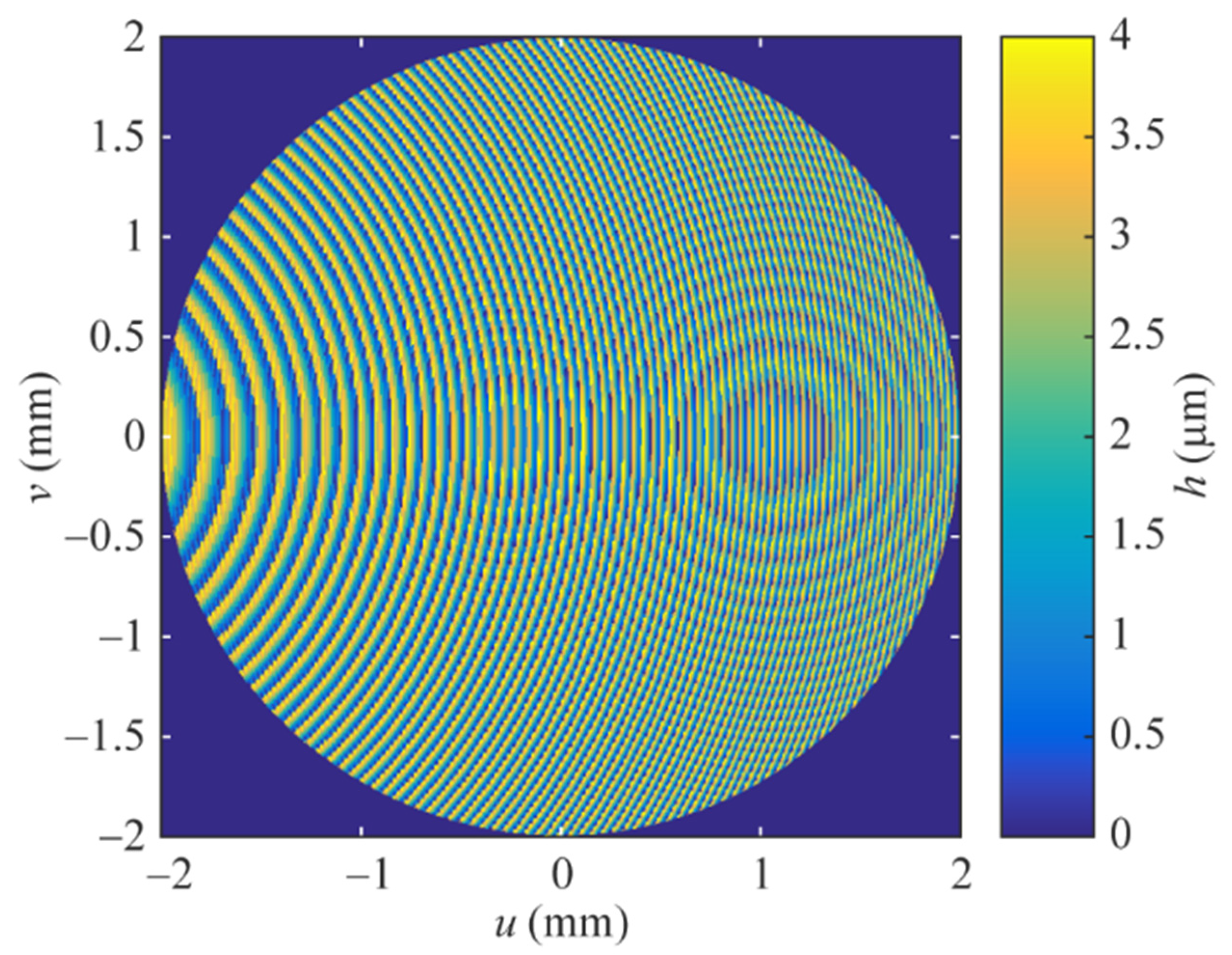
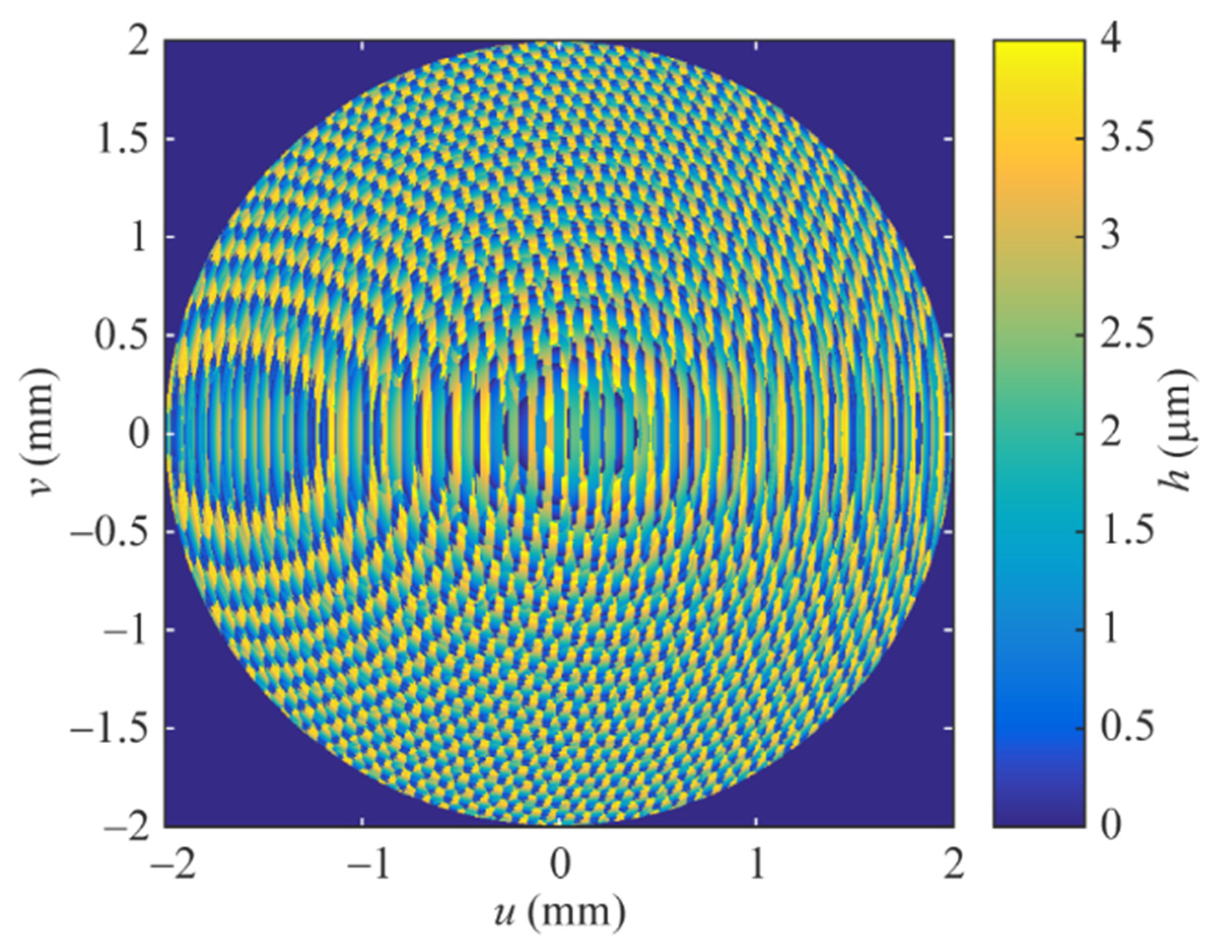
18]. The diffractive microreliefs (Figure 1 and 
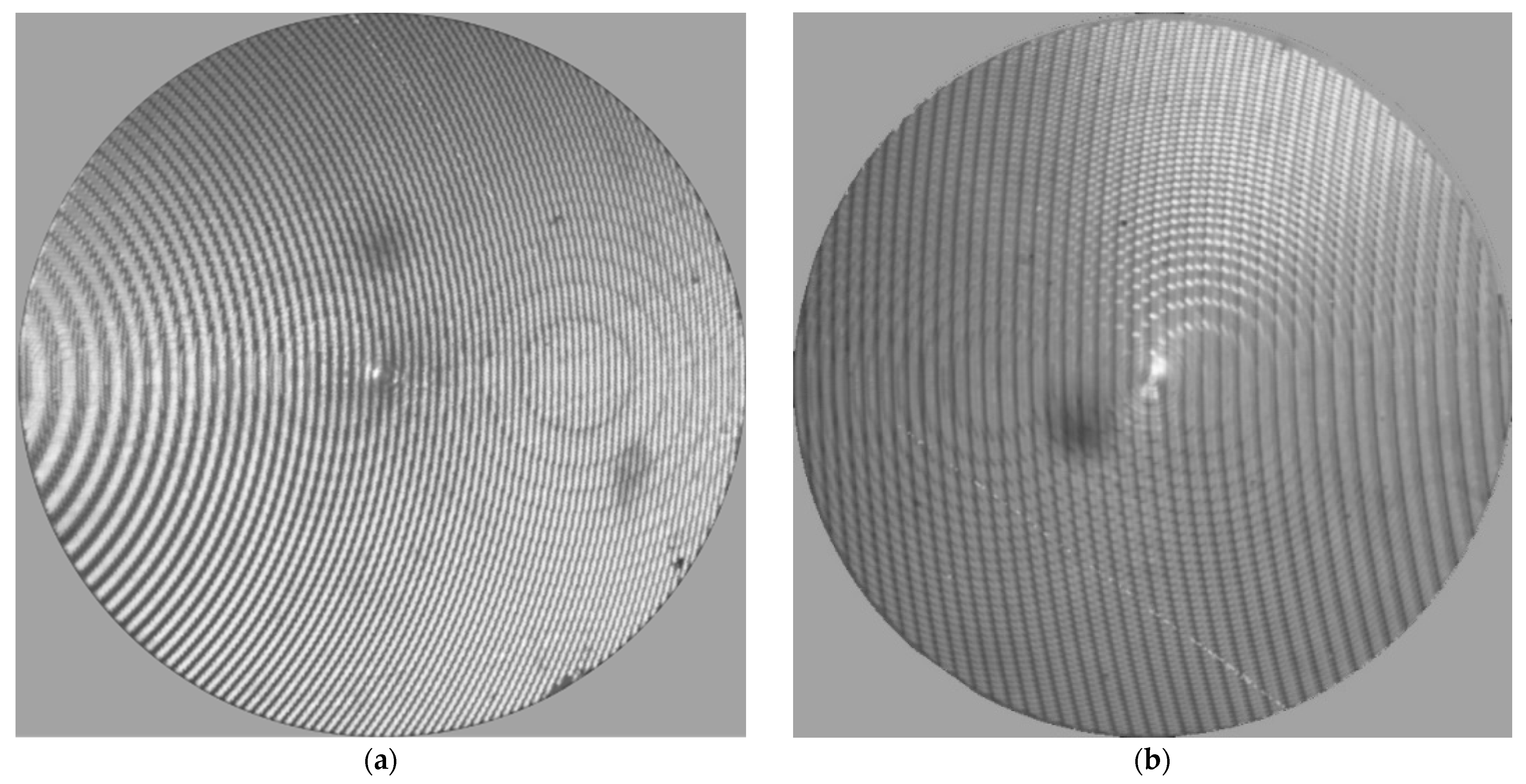
Figure 3) were patterned into a 4 μm layer of positive photoresist FP-3535, which was spin-coated on quartz substrates. The photographs of the fabricated MWDLs made through the objective of an optical microscope are presented in Figure 7. The results of interferometric measurements of different fragments of the microrelief of the fabricated MWDLs performed using a white-light interferometer NewView 7300 (not presented here for the sake of brevity) and their comparison with the corresponding laterally aligned “theoretical” fragments, demonstrated that the fabricated relief heights differ from the theoretical values by 100–150 nm.
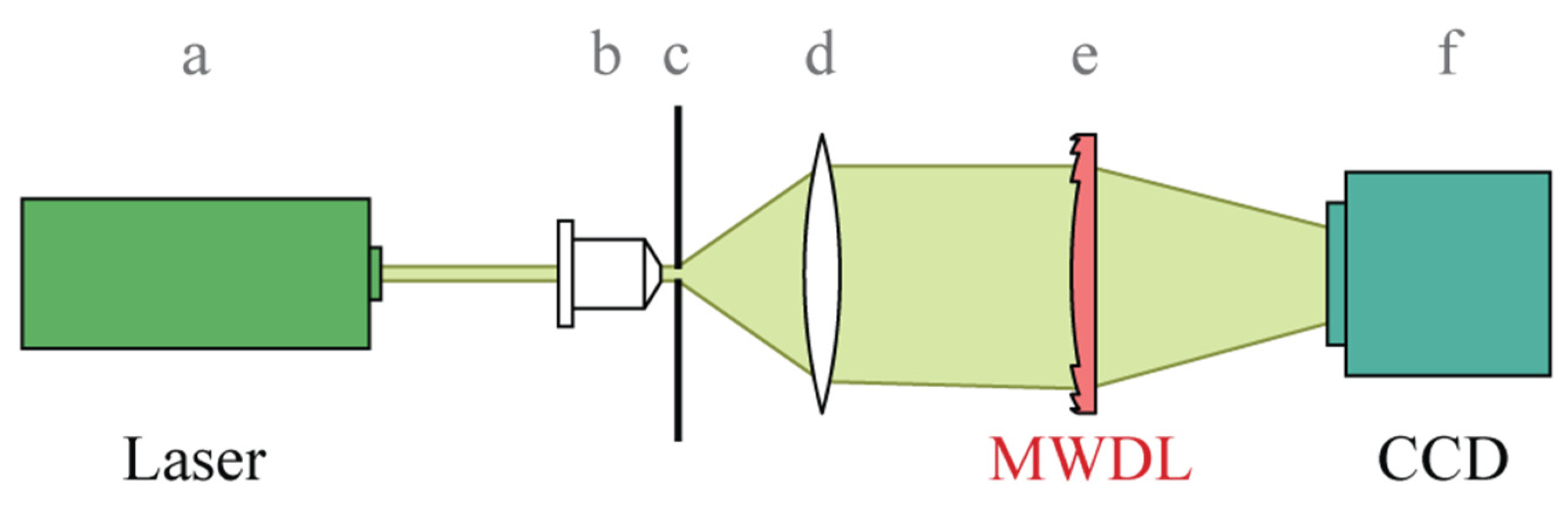
The fabricated MWDLs were investigated in an optical experiment for which the optical setup schematically shown in Figure 8 was assembled. This setup operates in the following way. A tunable laser (a) generates a beam with the required wavelength, which is focused by a micro-objective (b) on a pinhole diaphragm (c). Then, a lens (d) (chosen together with the micro-objective (b) to form an approximately achromatized system in the considered range) generates a collimated beam, which impinges on the investigated MWDL (e). Finally, the intensity distribution generated by the MWDL is registered by the CCD sensor (f).
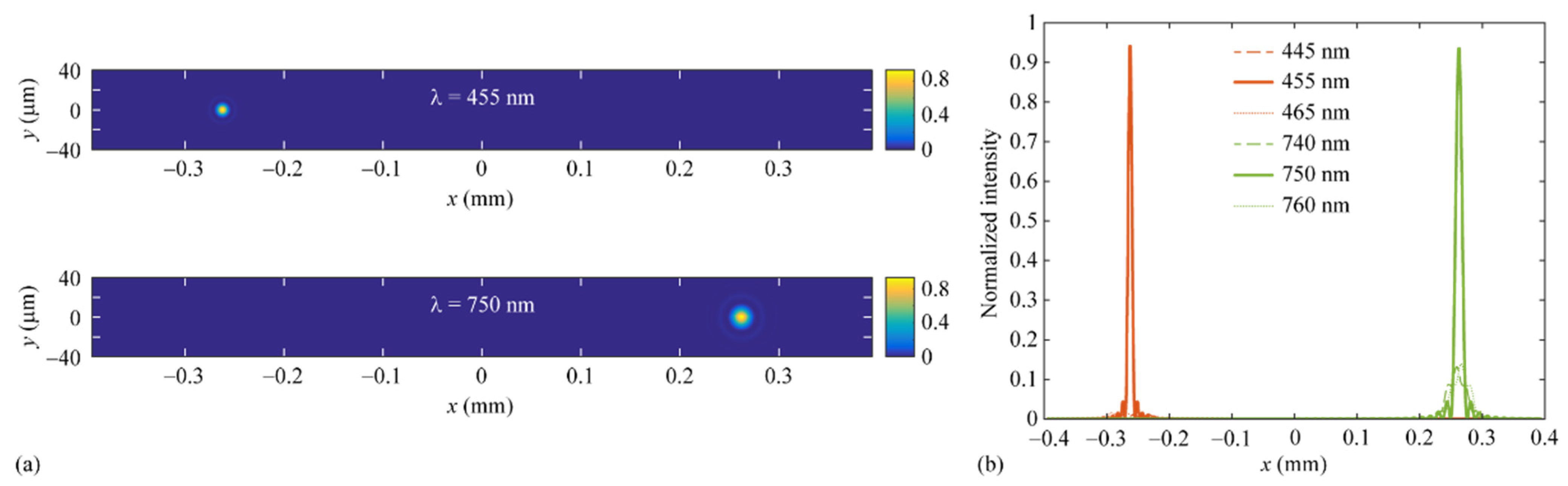
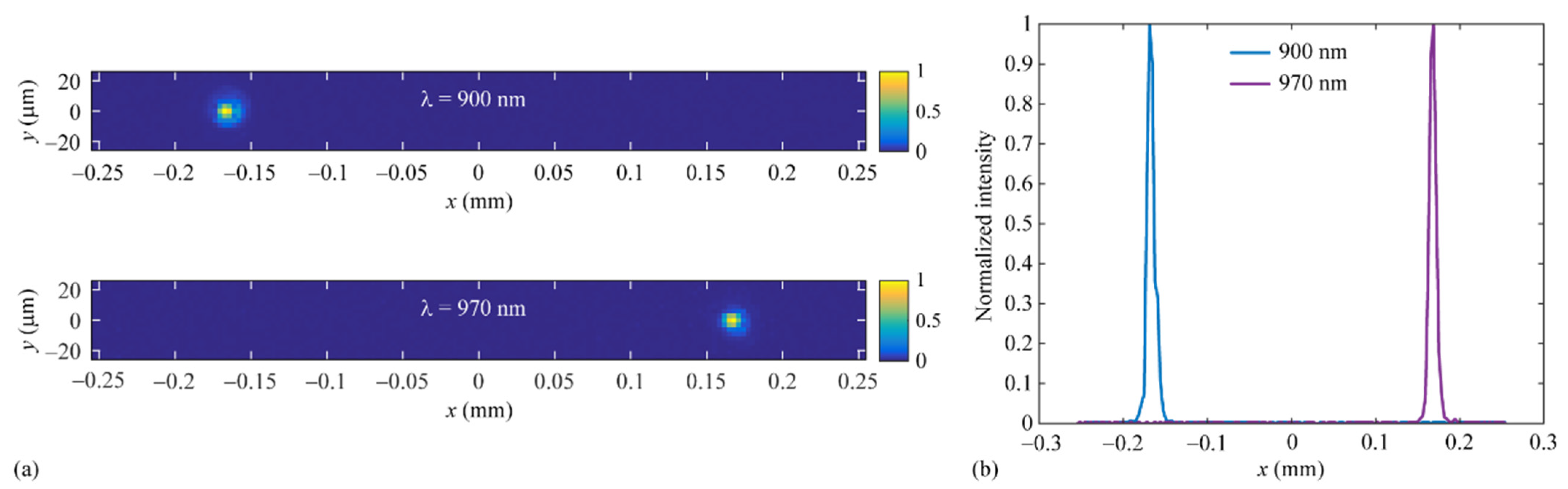
Figure 9a shows the measured irradiance distributions (point spread functions) generated by the MWDL of Figure 7a at the design wavelengths λ 1 = 455   nm and λ 2 = 750   nm . The presented distributions are normalized by maximum values and are presented in the same region as the calculated distributions shown in Figure 2a. Figure 9b demonstrates the cross-sections of the measured two-dimensional distributions along the x axis. The measured distributions shown in Figure 9 are in a reasonably good agreement with the numerical simulation results presented in Figure 2. A slightly “smoothed” appearance of the measured distributions is caused by both inaccuracies in the MWDL fabrication and a relatively large pixel size of the used sensor ( 3.2 × 3.2   μ m 2 ).
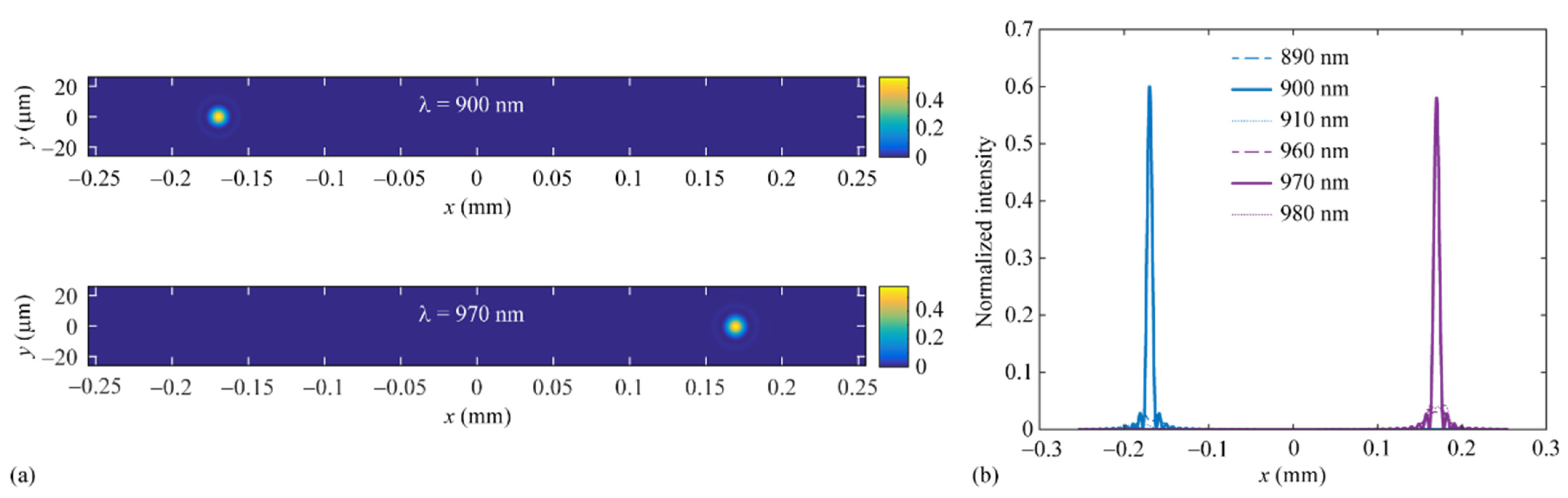
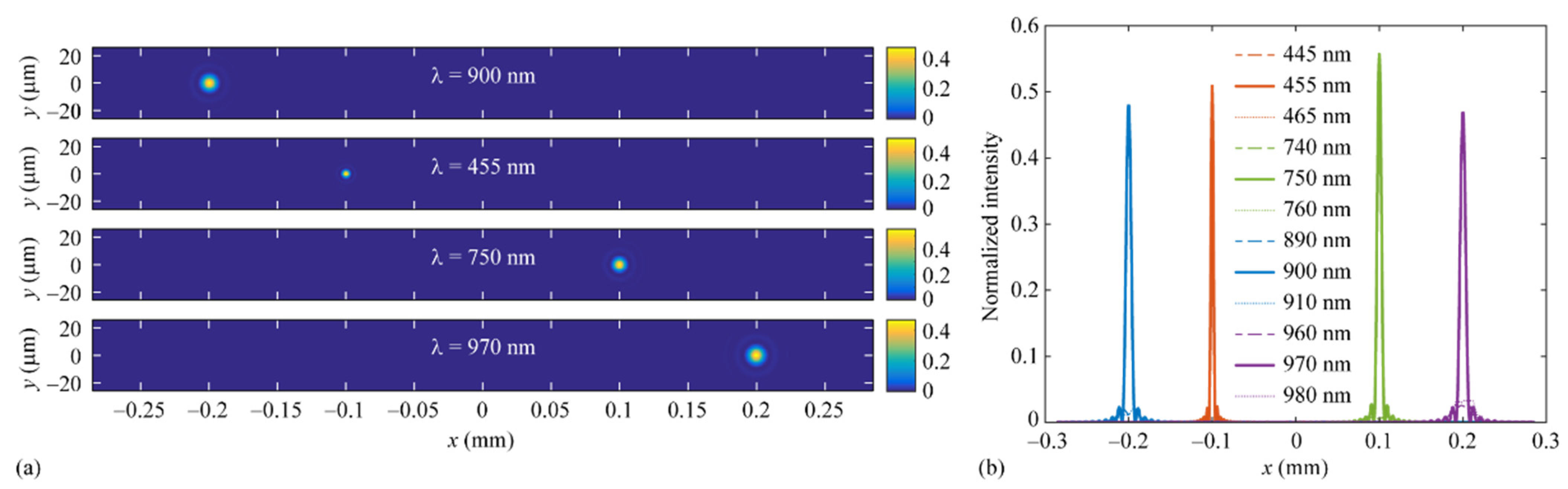
Figure 10 shows the normalized measured point spread functions for the MWDL of Figure 7b designed for separating and focusing to two different points the radiation with the wavelengths λ 1 = 900   nm and λ 2 = 970   nm . As above, the measured distributions are shown in the same region as the corresponding calculated distributions presented in Figure 4. Similar to the previous example, the comparison of Figure 4 and Figure 10 shows that the measured distributions in Figure 9 are in a reasonable agreement with the numerical simulation results in Figure 4. Again, slightly “smoothed” measured distributions are due to MWDL fabrication errors and the relatively large pixel size of the sensor.

5. Conclusions

We proposed a method for calculating multi-wavelength diffractive lenses for separating and focusing the radiation of L different wavelengths to L different points. The method is based on minimizing an objective function describing the deviation of the complex transmission functions of the MWDL at the design wavelengths from the complex transmission functions of diffractive lenses designed separately for each of these wavelengths. In the method, the MWDL calculation is reduced to a set of independent optimization problems, each of which describes the calculation of the MWDL microrelief height at a single point.
As examples, we designed two MWDLs for separating and focusing pairs of wavelengths corresponding to the modified red edge simple ratio index and the water band index. In addition, an MWDL was calculated for separating and focusing four wavelengths corresponding to both mentioned vegetation indices. The presented numerical simulation results confirm high performance of the designed MWDLs. Using the direct laser writing technique, we fabricated two MWDLs for separating and focusing the wavelengths corresponding to the MRESR index and the WB index. The results of the experimental investigation of the fabricated MWDLs are in a reasonably good agreement with the numerical simulation results and additionally confirm the correctness of the proposed method for the MWDL design.
We believe that the proposed MWDLs can be utilized for the analysis of the vegetation cover using several different optical setups. In the simplest case, one can use a lens shade to ensure that the beam incident on the MWDL is close to a normally incident collimated one. In this case, the MWDL will “extract” and focus the wavelengths required for the calculation of the vegetation index of interest. To perform a full analysis of a vegetation index within a certain angle of view, angular scanning can be performed. The application of the MWDLs in spectral sensors aimed at such analysis will be the topic of a further research.
Let us also note that the proposed method can be easily generalized to the problem of designing MWDLs focusing the different wavelengths to different points in space (i.e., not located in the same plane), as well as to the problem of designing multi-wavelength diffractive optical elements (DOEs) generating different light patterns for different operating wavelengths. In the latter case, the complex transmission functions of the DOEs generating the prescribed patterns at the design wavelengths have to be used in the optimized objective function instead of the lens transmission functions.

Author Contributions

Conceptualization, L.L.D.; methodology, L.L.D. and R.V.S.; software, L.L.D. and E.A.B.; validation, L.L.D., V.V.P. and N.V.G.; investigation, L.L.D., V.A.B., S.V.G., V.V.P., E.A.B. and D.A.B.; resources, R.V.S.; writing—original draft preparation, L.L.D. and E.A.B.; writing—review and editing, L.L.D. and E.A.B.; visualization, D.A.B. and E.A.B.; supervision, L.L.D. and R.V.S.; project administration, L.L.D., N.V.G. and R.V.S.; funding acquisition, N.V.G., R.V.S. and L.L.D. All authors have read and agreed to the published version of the manuscript.

Funding

This work was funded by the Ministry of Science and Higher Education of the Russian Federation [state assignment for research to Samara University (laboratory “Photonics for Smart Home and Smart City”, project FSSS-2021-0016), development of the design method for calculating multi-wavelength diffractive lenses, design, fabrication and experimental investigation of multi-wavelength diffractive lenses; and state assignment to the FSRC “Crystallography and Photonics” RAS (agreement 007-GZ/Ch3363/26), implementation of the diffractive lens simulation software].

Institutional Review Board Statement

Not applicable.

Informed Consent Statement

Not applicable.

Data Availability Statement

The data that support the presented results are available from the corresponding author upon reasonable request.

Conflicts of Interest

The authors declare no conflict of interest.

References

  1. Sweeney, D.W.; Sommargren, G.E. Harmonic diffractive lenses. Appl. Opt. 1995, 34, 2469–2475. [Google Scholar] [CrossRef] [PubMed]
  2. Rossi, M.; Kunz, R.E.; Herzig, H.P. Refractive and diffractive properties of planar micro-optical elements. Appl. Opt. 1995, 34, 5996–6007. [Google Scholar] [CrossRef] [PubMed] [Green Version]
  3. Faklis, D.; Morris, G.M. Spectral properties of multiorder diffractive lenses. Appl. Opt. 1995, 34, 2462–2468. [Google Scholar] [CrossRef] [PubMed] [Green Version]
  4. Banerji, S.; Meem, M.; Majumder, A.; Vasquez, F.G.; Sensale-Rodriguez, B.; Menon, R. Imaging with flat optics: Metalenses or diffractive lenses? Optica 2019, 6, 805–810. [Google Scholar] [CrossRef]
  5. Meem, M.; Banerji, S.; Majumder, A.; Vasquez, F.G.; Sensale-Rodriguez, B.; Menon, R. Broadband lightweight flat lenses for long-wave infrared imaging. Proc. Natl. Acad. Sci. USA 2019, 116, 21375–21378. [Google Scholar] [CrossRef] [PubMed] [Green Version]
  6. Wang, P.; Mohammad, N.; Menon, R. Chromatic-aberration corrected diffractive lenses for ultra-broadband focusing. Sci. Rep. 2016, 6, 21545. [Google Scholar] [CrossRef] [PubMed] [Green Version]
  7. Mohammad, N.; Meem, M.; Shen, B.; Wang, P.; Menon, R. Broadband imaging with one planar diffractive lens. Sci. Rep. 2018, 8, 2799. [Google Scholar] [CrossRef] [PubMed] [Green Version]
  8. Banerji, S.; Sensale-Rodriguez, B. A computational design framework for efficient, fabrication error-tolerant, planar THz diffractive optical elements. Sci. Rep. 2019, 9, 5801. [Google Scholar] [CrossRef] [PubMed] [Green Version]
  9. Meem, M.; Banerji, S.; Majumder, A.; Pies, C.; Oberbiermann, T.; Sensale-Rodriguez, B.; Menon, R. Inverse-designed achromatic flat lens enabling imaging across the visible and near-infrared with diameter > 3 mm and NA = 0.3. Appl. Phys. Lett. 2020, 117, 041101. [Google Scholar] [CrossRef]
  10. Meem, M.; Majumder, A.; Banerji, S.; Garcia, J.C.; Kigner, O.B.; Hon, P.W.C.; Sensale-Rodriguez, B.; Menon, R. Imaging from the visible to the longwave infrared wavelengths via an inverse-designed flat lens. Opt. Express 2021, 29, 20715–20723. [Google Scholar] [CrossRef] [PubMed]
  11. Kigner, O.; Meem, M.; Baker, B.; Banerji, S.; Hon, P.W.C.; Sensale-Rodriguez, B.; Menon, R. Monolithic all-silicon flat lens for broadband LWIR imaging. Opt. Lett. 2021, 46, 4069–4071. [Google Scholar] [CrossRef] [PubMed]
  12. Doskolovich, L.L.; Skidanov, R.V.; Bezus, E.A.; Ganchevskaya, S.V.; Bykov, D.A.; Kazanskiy, N.L. Design of diffractive lenses operating at several wavelengths. Opt. Express 2020, 28, 11705–11720. [Google Scholar] [CrossRef] [PubMed]
  13. Doskolovich, L.L.; Bezus, E.A.; Bykov, D.A.; Skidanov, R.V.; Kazanskiy, N.L. Calculation of a diffractive lens having a fixed focal position at several prescribed wavelengths. Comput. Opt. 2019, 43, 946–955. [Google Scholar] [CrossRef]
  14. Chen, W.T.; Zhu, A.Y.; Sanjeev, V.; Khorasaninejad, M.; Shi, Z.; Lee, E.; Capasso, F. A broadband achromatic metalens for focusing and imaging in the visible. Nat. Nanotechnol. 2018, 13, 220–226. [Google Scholar] [CrossRef] [PubMed] [Green Version]
  15. Liang, Y.; Liu, H.; Wang, F.; Meng, H.; Guo, J.; Li, J.; Wei, Z. High-efficiency, near-diffraction limited, dielectric metasurface lenses based on crystalline titanium dioxide at visible wavelengths. Nanomaterials 2018, 8, 288. [Google Scholar] [CrossRef] [PubMed] [Green Version]
  16. Bannari, A.; Morin, D.; Bonn, F.; Huete, A.R. A review of vegetation indices. Remote Sens. Rev. 1995, 13, 95–120. [Google Scholar] [CrossRef]
  17. L3 Harris Geospatial documentation center (Harris Geospatial Solutions), Narrowband Greenness. Available online: https://www.harrisgeospatial.com/docs/NarrowbandGreenness.html (accessed on 3 October 2022).
  18. Verhoglyad, A.G.; Zavyalova, M.A.; Kachkin, A.E.; Kokarev, S.A.; Korolkov, V.P. Circular laser writing system for generating phase and amplitude microstructures on spherical surfaces. Sens. Syst. 2015, 9–10, 45–52. (In Russian) [Google Scholar]
Figure 1. Microrelief of the MWDL focusing the wavelengths λ 1 = 455   nm and λ 2 = 750   nm to two points.
Photonics 09 00785 g001
Figure 2. (a) Normalized two-dimensional intensity distributions generated by the calculated MWDL at the design wavelengths λ 1 = 455   nm (top) and λ 2 = 750   nm (bottom); (b) Cross-sections of the normalized intensity distributions along the x axis for the wavelengths λ 1 , λ 1 ± 10 nm and λ 2 , λ 2 ± 10   nm .
Photonics 09 00785 g002
Figure 3. Microrelief of the MWDL focusing the wavelengths λ 1 = 900   nm and λ 2 = 970   nm to two points.
Photonics 09 00785 g003
Figure 4. (a) Normalized two-dimensional intensity distributions generated by the calculated MWDL at the design wavelengths λ 1 = 900   nm (top) and λ 2 = 970   nm (bottom); (b) Cross-sections of the normalized intensity distributions along the x axis for the wavelengths λ 1 , λ 1 ± 10 nm and λ 2 , λ 2 ± 10   nm .
Photonics 09 00785 g004
Figure 5. Microrelief of the MWDL focusing the wavelengths λ 1 = 900   nm , λ 2 = 455   nm , λ 3 = 750   nm , and λ 4 = 970   nm to four points.
Photonics 09 00785 g005
Figure 6. (a) Normalized two-dimensional intensity distributions generated by the calculated MWDL at the design wavelengths λ 1 = 900   nm (top panel), λ 2 = 455   nm (second panel from the top), λ 3 = 750   nm (third panel from the top), and λ 4 = 970   nm (bottom panel); (b) Cross-sections of the normalized intensity distributions along the x axis for the wavelengths λ 1 , λ 1 ± 10 nm , λ 2 , λ 2 ± 10   nm , λ 3 , λ 3 ± 10 nm , and λ 4 , λ 4 ± 10   nm .
Photonics 09 00785 g006
Figure 7. Fabricated MWDLs focusing the wavelengths λ 1 = 455   nm , λ 2 = 750   nm (a) and λ 1 = 900   nm , λ 2 = 970   nm (b) to two points.
Photonics 09 00785 g007
Figure 8. Optical setup for measuring the point spread functions of an MWDL: (a)—tunable laser NT-242, (b)—20× micro-objective, (c)—pinhole diaphragm with the diameter of 10 μm, (d)— collimating lens, (e)—MWDL, (f)—CCD sensor ToupCam UCMOS03100KPA (pixel dimensions 3.2 × 3.2 μm2).
Photonics 09 00785 g008
Figure 9. (a) Normalized measured two-dimensional intensity distributions generated by the fabricated MWDL [Figure 7a] at the design wavelengths λ 1 = 455   nm and λ 2 = 750   nm ; (b) Cross-sections of the normalized distributions along the x axis.
Photonics 09 00785 g009
Figure 10. (a) Normalized measured two-dimensional intensity distributions generated by the fabricated MWDL [Figure 7b] at the design wavelengths λ 1 = 900   nm and λ 2 = 970   nm ; (b) Cross-sections of the normalized distributions along the x axis.
Photonics 09 00785 g010
Publisher’s Note: MDPI stays neutral with regard to jurisdictional claims in published maps and institutional affiliations.

