1. Introduction
The advent of low-loss hollow-core optical fibers (HCFs) [
1] enabled the development of a new type of lasers–gas fiber lasers (GFLs). The invention of a particular type of HCFs–revolver fibers [
2,
3]–boosted the GFL developments significantly, since revolver fibers have simple design, well predictable optical properties, and become available for increasing number of researchers.
To date, various GFLs have already been demonstrated. An active medium of such lasers is some Raman-active [
4] or dipole-active [
5,
6,
7,
8] gas that fills the hollow-core of a fiber. To excite the active medium, the GFLs rely on optical pumping by some solid-state laser. Thus, strictly speaking, all GFLs demonstrated so far are in fact not generators, but only converters of pump laser radiation. As a result, the GFL characteristics are limited by the limiting parameters of the pump laser. In order to fully realize the possibilities of hollow fibers (resistance to high-intensity radiation, wide spectral transmission range, etc.) in all-fiber optical schemes, it is necessary to solve the problem of generating laser radiation directly in HCF without using other solid-state lasers, which have inherent limitations as pump sources. This goal can, in principle, be achieved by using an electric discharge to excite the active medium of a GFL. Thus, the development of gas-discharge fiber lasers (GDFLs) based on hollow-core fibers is of high importance.
The design of a light waveguide gas laser (but not yet in a fiber version) was considered in detail in a theoretical paper back in 1964 [
9]. It was first implemented in 1971 in the form of a 633 nm helium-neon laser [
10], in 1972 in the form of a CO
2 laser [
11]. We also note the demonstration of a waveguide helium-neon laser at 3.39 µm in 1975 [
12]. In all these cases, a glass capillary with an inner diameter of 3.3 mm [
11], 430 µm [
10], and 510 µm [
12] was used as a waveguide for the generated radiation. Reducing the diameter of the waveguide helps to reduce bending optical losses in it. In addition, a decrease in the discharge tube diameter usually leads to an increase in the optical gain in the gas discharge plasma. But already at the inner diameter of the capillaries of about 0.5 mm, the researchers encountered the instability of the electric discharge. In a number of studies, this effect was overcome by using combined electric pumping. E.g., combination of direct current (DC) and radio-frequency (RF) pumping was used in [
10] and a combination of DC and microwave (MW) pumping was demonstrated in [
12]. As a result, waveguide gas lasers based on rigid capillary waveguides are still used, but the use of capillary waveguides, which must be kept straight to ensure low optical losses [
9], usually limits their length to several tens of centimeters.
The attempts to create gas-discharge fiber lasers started about 15 years ago, shortly after the development of HCFs. The main problem here is the difficulty of maintaining plasma in a thin (about 100 μm in diameter) core. The HCF diameter of the order of ~100 μm was used in almost all studies, since it provides an acceptable level of optical losses in a HCF. As far as we know, the first studies on the way to GDFL were carried out at the Hong Kong Polytechnic University in 2007–2008 [
13,
14,
15]. In these works, the discharge was excited by a DC voltage of ~10 kV both in glass capillaries and in HCFs with various diameters of a hollow core. From the point of view of electric discharge maintenance, the differences between an ordinary capillary and a HCF with identical holes are not essential. Note, that an ordinary glass capillary is in fact also a fiber with a hollow core (as was shown in [
9]). In these works, the ignition and maintenance of a discharge in glass capillaries and HCFs with an inner diameter of
dC = 344, 250, 150, 50, and 20 µm in Ar, He, and CO
2 at pressures of about 20 Torr were demonstrated. The lengths of the fiber segments between the electrodes ranged from 13 to 2.9 cm. Using higher voltages (~30 kV), the discharge could be initiated in a fiber segment with an inner diameter of 250 μm and a length of 26 cm [
15].
The next series of works on GDFLs with the discharge excitation by a DC electric field was carried out at the University of Bath [
16,
17,
18,
19]. Already in 2014, the optical amplification was reported in an electrically pumped gas laser in a hollow fiber [
16]. For pumping, a DC electric discharge with a voltage of up to 40 kV was used. A 5:1 He:Xe mixture was used at a total pressure of ~10 Torr. The diameter of the revolver type HCF core was
dC = 120 μm. When a 100% reflecting mirror was added at one end of the fiber, the luminescence level at the output on the other end of the fiber increased by more than a factor of 2, which was interpreted by the authors as an amplification of radiation due to stimulated transitions in the Xe atom. The amplification was registered in this way at wavelengths of 3.11, 3.37, and 3.51 μm. However, this result has not received further development so far.
Finally, in a number of works performed at the University of Limoges, the possibilities of excitation of an electric discharge in HCFs using electromagnetic waves in the MW frequency range were studied (see review [
20]). Indeed, in a number of parameters, gas laser schemes with MW discharge excitation can have a significant advantage over excitation by a DC or RF fields [
21,
22]. The obtained results demonstrated the possibility of ignition and maintenance of an electric discharge in a hollow fiber with a core diameter
dC = 125 μm filled with argon under the action of a MW field source with a frequency of 2.45 GHz and a power of about 200 W [
23]. The discharge was maintained in the fiber core by excitation of a surface electromagnetic wave propagating along the plasma column filling the HCF core. The surface electromagnetic wave was formed using a special device called surfatron [
20], which contains a resonator for MW radiation. As has been demonstrated earlier [
24], such a device is able to effectively excite a MW discharge in tubes of large diameter (~1 cm). The length of the discharge plasma region in the HCF was limited to ~4 cm. The argon pressure was about 1 Torr. So far no optical amplification has been reported with such a scheme, but it has been proposed to use it as a source of the UV radiation.
The use of RF fields makes it possible to circumvent the electrodes problem (sputtered particles of electrodes can destroy the light-guide properties of HCFs), but otherwise differs little from a DC discharge excitation [
25]. In addition, generating the required fields in the RF range presents significantly greater difficulties than for the case of DC and the microwave.
The most promising frequency range for pumping GDFLs is apparently the MW range. The transition to frequencies of the order of 3 GHz leads to the fact that the amplitude of electron oscillations in the field becomes of the order of or less than the diameter of the hollow core, which reduces the probability of electron loss on the walls of the fiber compared to fields of lower frequencies. In addition, the widespread use of magnetrons operating at a frequency of 2.45 GHz in household appliances (in widespread MW ovens) has made sources of such radiation relatively cheap and widely available.
Therefore, the purpose of this work is to study a new method of a MW discharge excitation in hollow-core optical fibers. The scheme similar to a slot antenna in the wall of a metal MW waveguide is proposed and implemented for the first time to excite the MW discharge in gas-filled hollow-core fibers and capillaries of various core diameters. Argon was chosen as the model gas for experiments. MW radiation was delivered to the core of a fiber through its side surface in such a way that the electric field vector was perpendicular to the HCF axis. The obvious advantage of such a scheme is the absence of the need to use high voltages (of the order of ten kilovolts) to maintain the discharge.
2. Microwave Structure for Energy Delivering to the Optical HCF
We used a magnetron operating at a frequency of ν = 2.45 GHz as a source of the MW field in studies of maintaining a gas discharge in HCFs. The magnetron operated in a pulsed mode. The pulse repetition rate was ~400 Hz, the pulse duration was ~20 μs. The maximum peak power reached 8 kW. A more detailed description of the source of MW radiation can be found in [
26].
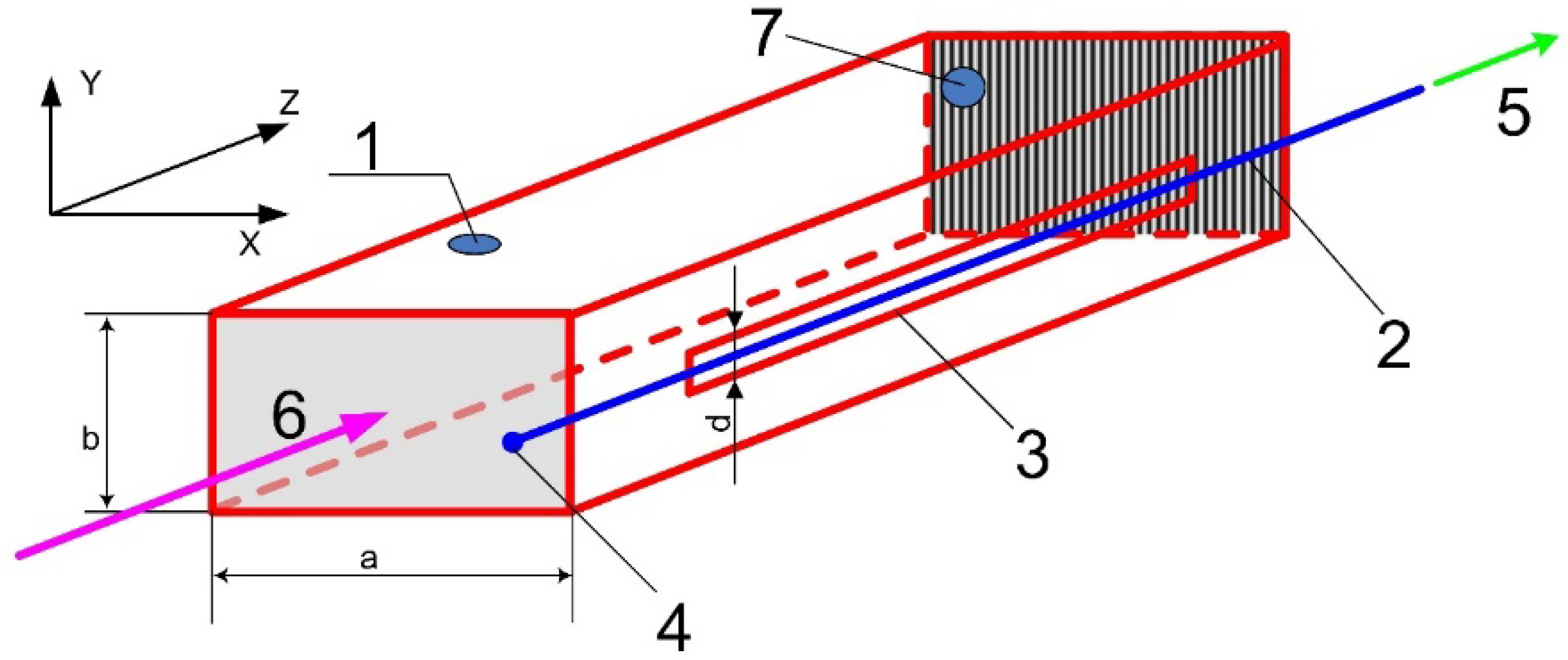
The magnetron radiation was launched into a rectangular waveguide with side dimensions
(see
Figure 1). The waveguide was single-mode for magnetron radiation, and only a H
10 mode propagated along it. The transverse dimensions of the waveguide are too large compared to the diameter of the HCF core (
) for the plasma in the fiber core to effectively absorb the energy of the MW field.
Therefore, to concentrate MW radiation on the HCF, we used a structure like a slot antenna: a longitudinal slot in the narrow side wall of a rectangular waveguide, along which MW radiation propagated from the magnetron (
Figure 1). The thickness of the copper walls of the waveguide was 2 mm. To form a slot antenna in the narrow wall of the waveguide in the direction of the Z axis, a slot 3 was cut. It’s length and width were
and
, correspondingly. The output end of the waveguide could be equipped with an adjustable short (
Figure 1, 7) in order to reflect back MW radiation.
The properties of such a slot antenna are well known (see, for example, [
27]). Inside the unperturbed waveguide (without a slot), the electric field of the
H10 mode is directed along the Y axis (it has only one component
EY), its maximum value
EY reaches at the center of side
a, and near the surface of the small side
b, the value of
EY is equal to zero, and therefore does not contribute to the electric field in the slot. The magnetic field of
H10 has two components:
HX and
HZ. In the absence of a slot, the
HZ component causes surface currents to flow along the narrow side of the waveguide in the Y direction. The slot crossing the direction of the Y axis prevents their flow, and electric charges arise at the edges of the slot, which form an electric field in the slot, directed across it (in this case, along the Y axis, see
Figure 1).
Due to the reflection from the sliding short 7 (
Figure 1) at the output of the waveguide, the formation of a standing wave is possible. Thus, if necessary, it is feasible in such a way to increase the amplitude of the electric field up to two times both on the axis of the waveguide and in the slot on its side surface. A similar scheme was used earlier to excite a discharge in planar gas lasers [
26,
28]. Note, however, that the presence of a short-circuiting plunger in the scheme (
Figure 1) is not necessary to maintain the discharge, so travelling-wave excitation schemes are possible in the future.
To evaluate the capabilities of the chosen scheme for maintaining a MW discharge in an argon-filled hollow core fiber, the following circumstances should be taken into account.
- (1)
As noted in [
29], the effective frequency of collisions of electrons with atoms for most gases can be expressed as
. The lowest electric field
required for gas breakdown is realized under the condition
, where
is the angular frequency of the MW field. For the frequency used by us, the minimum value of
corresponds to a pressure of 50 Torr, and the minimum value
turns out to be approximately 300 V/cm (the estimate was made using data from [
30]). To maintain a discharge in a gas (rather than for a gas breakdown), a lower electric field
is usually required (as, for example, in the case of optical discharges [
31]). So the given estimate (300 V/cm) for the value of
is an upper estimate. But when planning the experiment, we used it as an initial approximation.
- (2)
The amplitude of electron oscillations in the absence of collisions under the action of an alternating electric field decreases with increasing field frequency, which in turn reduces the rate of electron escape from the discharge to the walls [
29]. So, for
and electric field
, the amplitude of free oscillations of electrons will be ~20 microns. In the case of diffusion oscillations (when there are frequent collisions of electrons with atoms), the amplitude will be even smaller. Thus, when these parameters are implemented, the amplitude of electron oscillations in the discharge will be less than the radius of the hollow core of the fiber (the value of which is ~50 μm). This circumstance should reduce the rate of electron escape from the discharge to the fiber walls and, thus, provide the possibility of maintaining the discharge over the entire length of the HCF placed in the electric field.
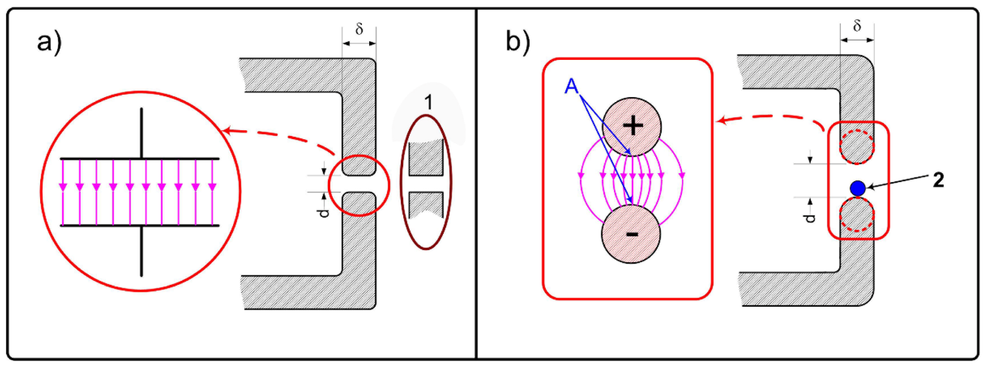
3. Evaluation of the Electric Field Distribution in a Slot
For the optimal placement of the HCF in the slot, it is necessary to estimate the distribution of the electric field in this region. If the influence of the capillary or HCF is not taken into account as an initial approximation, then the distribution and magnitude of the electric field in the slot far from its ends (which short-circuit the slot) can be relatively easily estimated provided that the slot width
d and the wall thickness of the MW waveguide
δ are much smaller than the wavelength of MW radiation. In this case, each section of the slot can be considered as a section of an electric circuit with lumped parameters. In particular, in some approximation, each section of the slot along the
Z axis of length
dz can be considered as (see
Figure 2) (a) a parallel-plate capacitor (PPC), or, in another approximation, as (b) an electric capacitance formed by a segment of a parallel-wire line (PWL), the minimum distance between the wires of which is equal to
d, and the diameter of the wires is equal to
δ (
Figure 2b).
Note that in PPC approximation (a) the field is better described for the case of a narrow slot (under the condition
d <<
δ), while approximation PWL (b) should work better in the case of
. We also note that the presence of pronounced angles in the cross section of the slot (convex sections of the conductive material with very small curvature radii) leads to the formation of regions with high electric field. In particular, near a corner close to a right angle (which can be formed during the manufacture of a slot in the side wall of the waveguide, as shown in
Figure 2a, 1), the electric field increases in proportion to
, where
r is the distance to the corner vertex (see, e.g., [
32]). With such geometry, an initial breakdown of atmospheric air near the edge can occur ahead of the breakdown of rarefied gas in the core of the HCF located in the slot. Therefore, the sharp edges of the slot in our experiments were carefully rounded and polished.
If a MW wave propagates along the waveguide (waveguide without slot) in the mode
H10 with power
, then the amplitude of the electric field on the waveguide axis is (see, e.g., [
33]):
Here Z0 = 377 Ohm is the impedance of the free space, is the critical wavelength (cutoff wavelength) for the fundamental mode H10. In particular, if the radiation power launched into the waveguide is PW = 1 kW (a typical value of the MW pulse maximal power in our experiments), then the maximum value of the electric field on the waveguide axis is Emax(1 kW) ≈ 220 V/cm.
It turns out that for the electric field in the waveguide slot in the approximations considered above (see
Figure 2), estimates can be obtained in analytical form under one additional condition. Considering the slot in the side wall as a perturbation of the waveguide, we will assume as an initial approximation that the formation of a narrow slot does not significantly affect the magnitude of the currents flowing through the walls of the waveguide. And the continuity of currents flowing across the slot, according to Maxwell’s equations, is provided by displacement currents.
As a result, we can obtain for the PPC approximation that the maximum value of the potential difference between the upper and lower edges of the slot is equal to
and, accordingly, the magnitude of the electric field in the slot is
In this approximation, the electric field in the slot is constant and does not depend on the slot width (provided that the approximation used is valid). It should be noted that the values of Umax and Esl clearly depend on the waveguide wall thickness.
If the edges of the slot are smoothed so that their shape becomes close to cylindrical with a radius
R =
δ/2 (
Figure 2b), then the field in the slot will obviously be close to the field between the conductors of a parallel wire line. For such a case, the field between the conductors can be expressed also in an analytical form (see, for example, [
34]). So, in the PWL approximation one can obtain:
In the PWL approximation, the magnitude of the electric field in the slot
Esl is not constant (in contrast to the PPC approximation) and depends on the position of the observation point relative to the edges of the slot. For each distance from the edge of the slot, the maximum values of the electric field are achieved on a straight line connecting the points of the upper and lower boundaries of the slot closest to each other. In turn, on this segment, the maximum values of
Esl are reached at the ends of this segment, namely, at the surfaces of the conductive walls of the slot (see
Figure 3a).
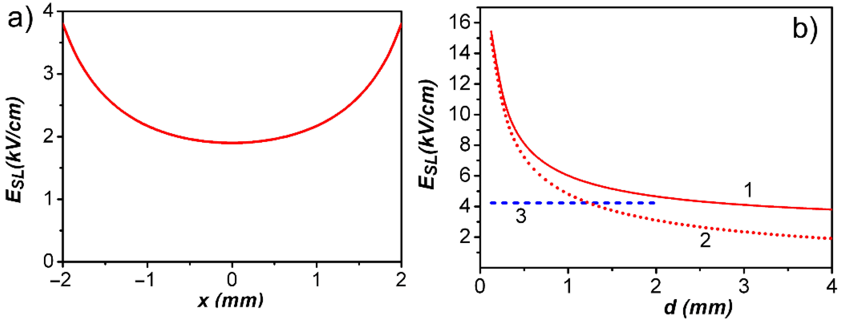
Figure 3b shows the calculated dependence of the electric field on the slot width (line 1) in the PWL approximation at the slot boundary, where the
Esl value is maximum (at points A in
Figure 2b) and also at the slot center (line 2). For comparison, the value of the electric field in the slot in the PPC approximation is given under the same conditions and for those values of
d where the PPC approximation should work (
d < 2
R) (line 3).
A comparison of lines 1, 2, and 3 in
Figure 3b shows that the magnitude of the transverse electric field
Esl in the slot depends significantly on the shape of the walls of the MW waveguide that bound the slot and on the width of the slot
d. With a rounded shape of the conductors limiting the slot, the value of
Esl increases sharply with decreasing
d.
Esl maximum values are limited by the minimum width of the slot, namely, by the diameter of the HCF, which is located in this slot. But due to the sharp dependence of the field on the slot width, it is necessary to keep the slot width constant with high accuracy, in addition, the shape of the cross section of the slot walls must also be precisely maintained (
Figure 2b). This is not an easy task, given that the length of the slot in the side wall of the waveguide is about 30 cm (this value is determined by the length of the plasma volume in the HCF, which is necessary to obtain sufficient optical amplification for operation of a gas-discharge fiber laser, and which should apparently be several tens of centimeters).
The variant of setting up the experiment with the implementation of the PPC approximation (
Figure 2a), apparently, can lead to an even more inhomogeneous field in the slot due to the need to simultaneously maintain the flatness and parallelism of the surfaces forming the slot. Based on the above estimates, we have chosen a scheme for the formation of a slot in the side wall of the waveguide, shown in
Figure 2b. In this case, HCF with a small diameter of the hollow core can be placed in the region of the maximum electric field—they were fixed directly on the horizontal border of the slot (see
Figure 2b, 2).
4. Experiment–Results and Discussion
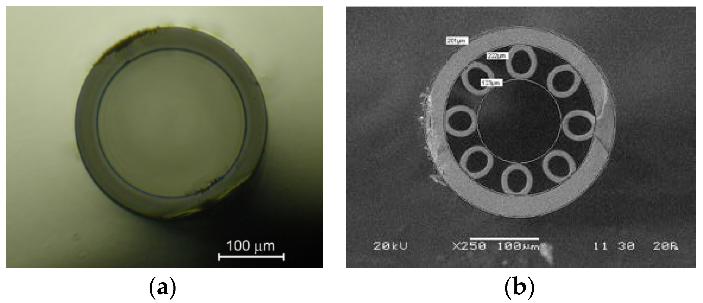
The experiments were carried out with argon-filled (under a pressure of units to tens of torr) capillaries made of pure silica glass (F300, Heraeus) with an inner diameter from 3 mm to 230 μm, as well as with revolver fibers with a hollow core diameter of 120 and 110 μm. Cross section pictures for some specimens are shown in
Figure 4. In the experiments, the width of the slot could be changed in the range from 1 to 4 mm with the help of special metal inserts. The geometry of the experiment corresponded to the scheme shown in
Figure 2b.
As mentioned above, the ignition (or initiation) of discharges of all types (including those under the action of a MW field) requires significantly higher values of the electric field than to maintain it after ignition. Thus, for example, a special initiation of an optical discharge by creating a seed plasma actually made it possible to study the propagation of an optical discharge along hollow fibers filled with air [
35]. In these experiments, to initiate an electric discharge in a waveguide under the action of a MW field, we used the pre-ionization of gas in HCFs and capillaries using UV radiation (as, for example, in [
36]).
After placing the capillary or HCF at the lower boundary of the slot in the side wall of the waveguide (see
Figure 2b, 2), it was connected to a vacuum system and pumped out to a pressure of about 10
−2 Torr. The total length of each capillary or HCF in the experiment was about 1 m. The time to vacuum HCF with a core diameter of 110 μm did not exceed 30 min. The required pump down time for capillaries and HCFs was approximately estimated using results of the work [
37]. Then the HCF was filled with argon to a pressure of several tens of Torr. After that, the magnetron was turned on, which operated in a repetitively pulsed regime. At the maximum peak power of the magnetron of ~2.5 kW, no electric discharge occurred in the capillaries and HCFs. To initiate it, a section of the capillary or HCF was irradiated for a short time (on the order of 1 s) with UV radiation from a mercury lamp. After that, the glow of the discharge in the capillary or HCF was observed almost throughout the entire length of the slot in the side wall of the waveguide. No additional continuous UV exposure was required. At intervals of 2.5 ms between 20 μs MW radiation pulses, each new pulse excited a MW discharge in the capillary without additional UV irradiation. This circumstance indicates that even after 2.5 ms (the interval between pulses) the capillary retains a sufficient concentration of electrons to initiate the discharge with the next pulse.
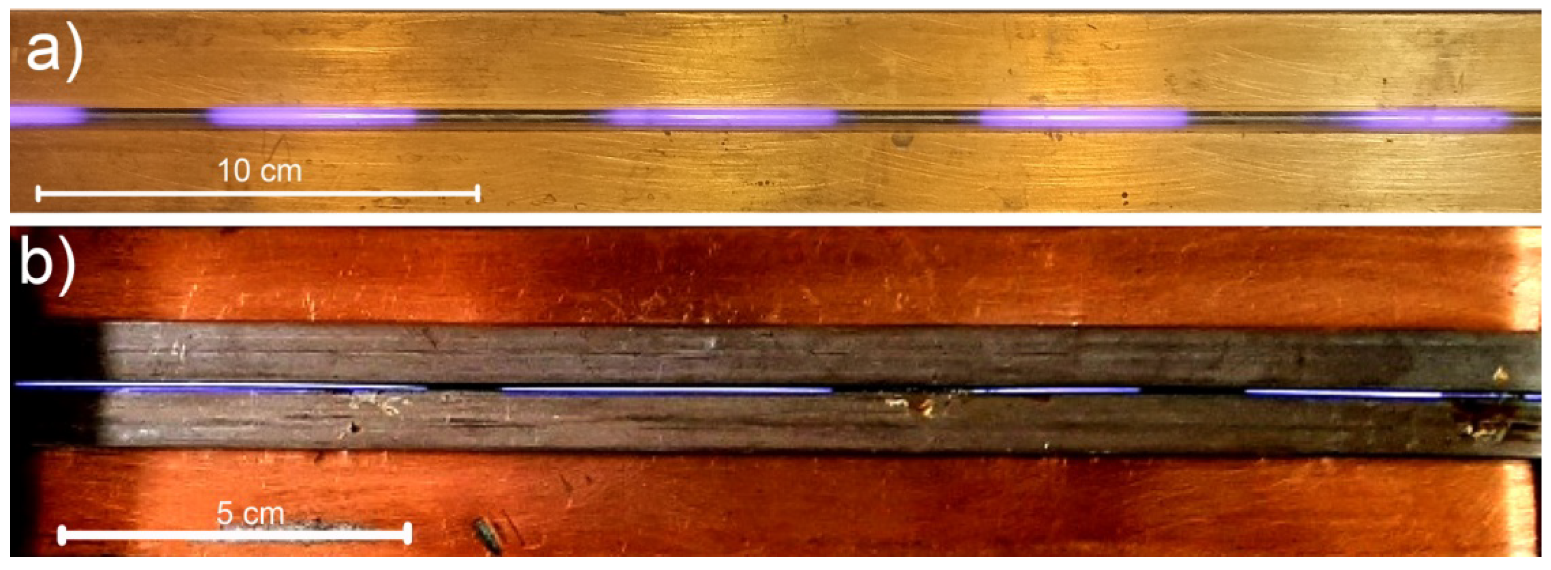
Typical pictures of a MW discharge in capillary and in HCF are shown in
Figure 5. The exposure time significantly exceeded the interval between MW pulses. These pictures were taken with a short-circuiting plunger placed at the exit of the waveguide (see
Figure 1). Due to the imperfection of the elements of the MW circuit (in particular, the non-optimal location of the short-circuiting plunger), the interference pattern of MW radiation in a waveguide with a slot differs somewhat from the simplest one that occurs when two identical waves of the same amplitude moving towards each other interfere. However, the MW discharge is observed over the entire length of the fiber section placed in the slot, except for relatively short sections in the vicinity of interference pattern nodes. The total length of the region occupied by the discharge in our experiments reached ~25 cm. Thus, we have demonstrated the possibility of maintaining an electric discharge in all the above capillaries with an inner diameter of 3 mm, 2 mm, and 1.3 mm, 230 μm, and HCFs with core diameters 120 μm and 110 μm at argon pressures from 20 to 50 Torr and MW power from 800 W to 2.4 kW in a maximum of 20 μs pulses (corresponding average MW power from 6.4 to 19.2 W).
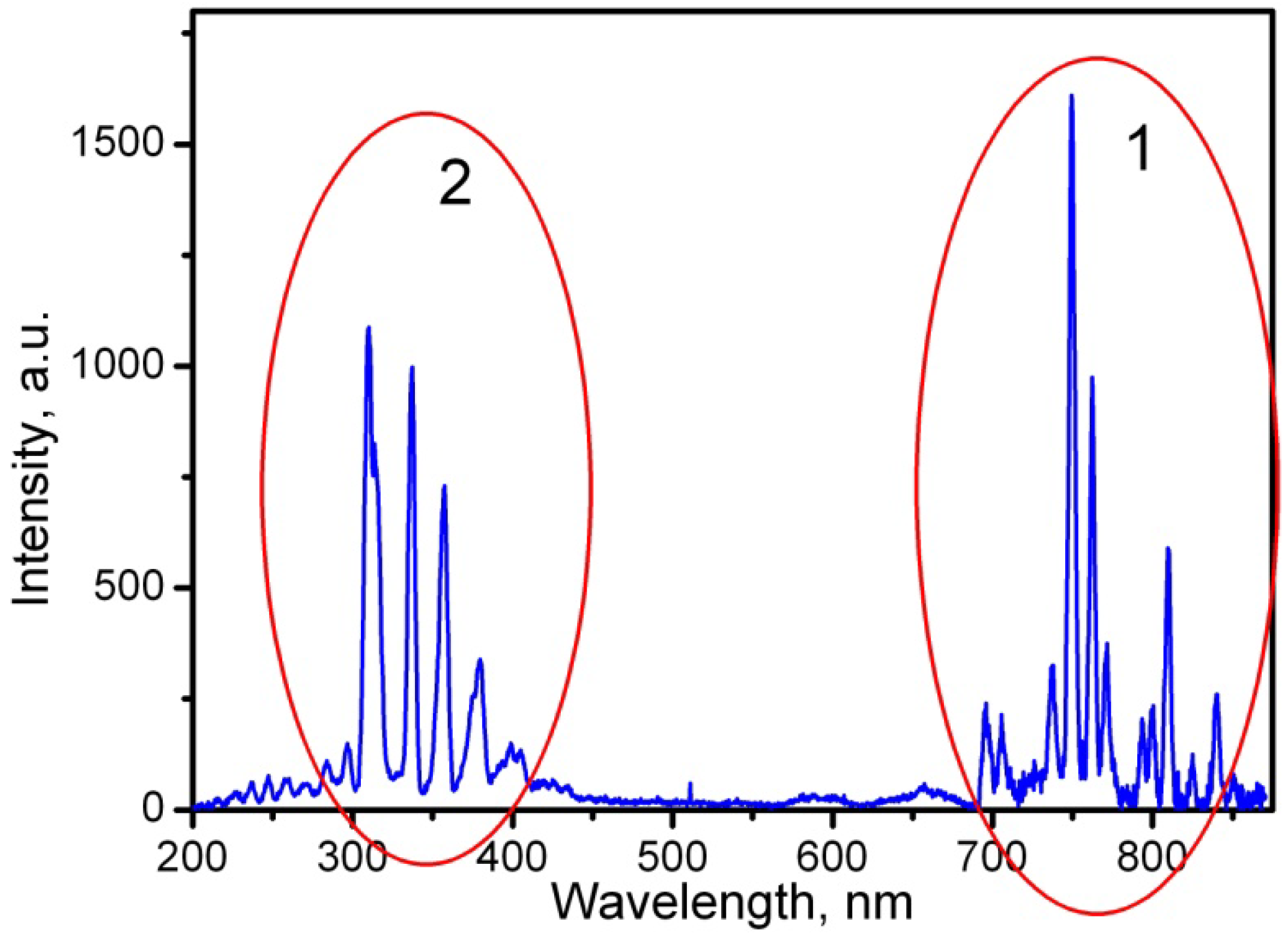
To evaluate the properties of argon plasma, its emission spectra were measured. The spectra were recorded in a wide wavelength range from 200 to 900 nm in the direction perpendicular to the axis of the optical fiber (through its side wall) using an Ocean Optics 2000 spectrum analyzer with a fiber input. An obtained typical spectrum is shown in
Figure 6. The spectrum consists of two main groups of lines. The group in the near-IR range, labeled 1, represents the lines of neutral argon atoms. The group in the near UV range, denoted 2, is a set of spectral lines of the OH group emission band (313 nm) and a number of lines of the N
2 nitrogen molecule (337 nm, 358 nm, 380 nm and 406 nm). The appearance of these lines is explained by the fact that in these experiments we used argon of insufficient purity. We note that similar spectra were observed in argon plasma, obtained, albeit under significantly different conditions, by other researchers [
38].
It is of interest to compare the emission spectra of argon obtained by us when a HCF was located in a slot in the side wall of the waveguide and obtained in [
39], where radiation of the same frequency was used to excite a MW discharge, but the MW energy was launched into the plasma using surface electromagnetic waves propagating along the boundary of the argon plasma in the Kagome-type HCF. The spectrum of the discharge in argon, obtained in [
39], in addition to the lines of neutral argon, also includes a group of lines of Ar
+ ions, which was not observed in our experiments. This fact is apparently due to differences in the schemes of excitation of the discharge. The use of surface electromagnetic waves implies an increased concentration of electrons in the discharge plasma, at which the plasma frequency should exceed the frequency of the MW field (2.45 GHz). Consequently, the concentration of electrons in the plasma when using surface waves should exceed 10
11 cm
−3. At the same time, in a glow discharge, which is used, for example, in He-Ne lasers, the electron density is usually
[
25]. Thus, in our experiments, the electron temperature is apparently lower than in [
39], and luminescence of only excited neutral argon atoms is observed. When excited by surface electromagnetic waves, the luminescence of both neutral atoms and ionized argon atoms was registered [
39].


