1. Introduction
In areas where high-quality laser pulses are desired, such as laser micromachining [
1,
2,
3,
4,
5,
6], ophthalmology [
7] and nonlinear microscopy [
8,
9,
10,
11], nonlinear optical effects such as self-phase modulation (SPM) often limit the achievable pulse energy of high-energy ultrafast laser systems. The nonlinear optical effects introduce nonlinear spectral and temporal phase to laser pulses. This nonlinear phase cannot be easily compensated for with a pulse compressor, resulting in decreased quality of compressed pulses [
12,
13]. This is especially true in fiber lasers, where the high-energy pulses are confined to a small fiber core. To overcome this problem, many advanced techniques have been demonstrated, among which is coherent beam combining [
14,
15], pulse stacking [
16], the use of tapered fiber amplifiers [
17,
18] and the use of optical fibers with large core diameters [
19,
20]. Although these systems offer some outstanding results in terms of power scaling, their relative complexity hinders their applicability in industrial laser applications. Another possibility for power scaling of fiber lasers is a hybrid laser design that, in addition to the fiber pre-amplifiers, implements an additional solid-state power-amplifier [
21,
22,
23]. The main advantage of this approach is that the beam diameter in a solid-state amplifier is much larger than fiber amplifiers. This results in increased pulse energies with negligible contributions to the nonlinear phase. However, even with the hybrid laser design, nonlinear optical effects remain a problem that needs to be addressed. This is even more crucial with lasers that operate in a broad range of pulse repetition rates while at the same time ensuring constant output pulse energies. This type of laser operation is becoming more and more desired in industrial and scientific applications, especially where the lasers are used in combination with fast scanning mechanism such as polygon or resonant scanners. Although the nonlinear effects are negligible in a solid-state amplifier, the gain reduces with increased laser power, i.e., with increased pulse repetition rate. This gain shortfall must be compensated for with increased gain in the fiber pre-amplifiers. Therefore, the gain in the fiber amplifier must be higher for higher pulse repetition rates in order to achieve constant output pulse energy. Higher gain in fiber pre-amplifiers directly relates to higher nonlinear phase. Varying the pulse repetition rate in hybrid lasers consequently results in variations in the accumulated nonlinear phase and therefore prohibits hybrid lasers from efficient operation over a broad range of pulse repetition rates with constant output pulse energy. To overcome this problem, the accumulated nonlinear phase must be compensated for and, what is more, it must be compensated for to a different extent at different pulse repetition rates. This shows the necessity for a tunable or adaptive compensation of nonlinear phase in hybrid laser systems.
There have been many methods already demonstrated that allow for tunable compensation of the nonlinear phase such as the use of different pulse-shaping techniques in a feedback loop with a pulse characterization technique at the laser output [
24,
25,
26,
27,
28,
29]. It was recently shown that a tunable chirped fiber Bragg grating (TCFBG) can efficiently compensate nonlinear phase up to 4π [
12]. As a TCFBG can also be used as a pulse stretcher in a chirped pulse amplification technique (CPA), its use for nonlinear phase compensation offers a clear advantage in terms of compactness and robustness compared to the use of spatial light modulators (SLM-s) or other pulse-shaping techniques [
30,
31,
32,
33,
34,
35,
36].
In this work, we demonstrate an inherent need for a tunable nonlinear phase compensation method in a typical hybrid laser that operates at a broad range of pulse repetition rates and with a constant output pulse energy. We demonstrate that, due to the lower gain in the solid-state amplifier, the pulse parameters deteriorate with increasing pulse repetition rate. Further, we show that the degree of deterioration varies with selected pulse repetition rate. We further demonstrate that a tunable method of nonlinear phase compensation based on a TCFBG can be efficiently utilized to overcome this problem. With this method, we manage to achieve constant output laser pulse parameters such as pulse energy, pulse duration and Strehl ratio at varying pulse repetition rates ranging from 100 kHz up to 2 MHz in a hybrid laser consisting of three fiber pre-amplifiers and one additional solid-state amplifier.
2. Experimental Setup
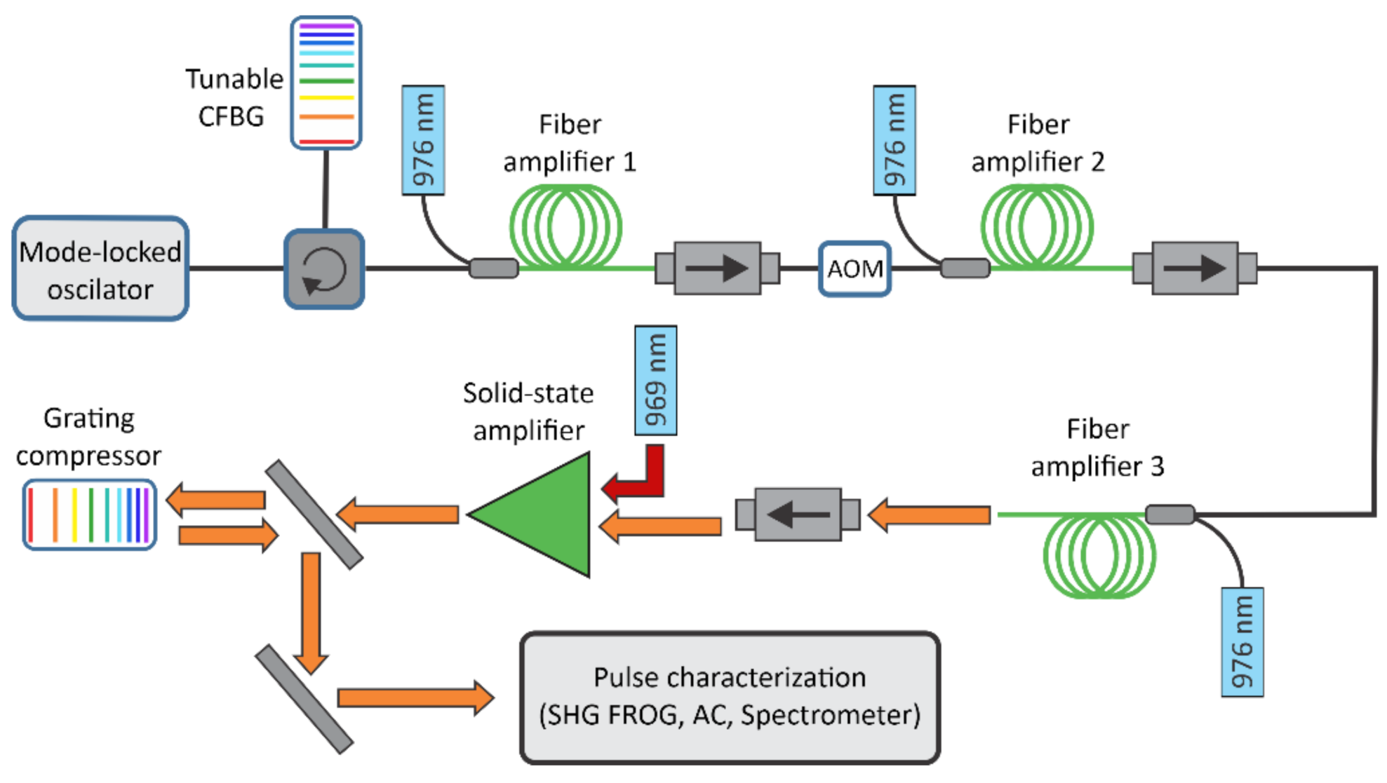
The experimental setup is shown in
Figure 1. The laser system was designed in a master oscillator power amplifier (MOPA) configuration, starting with a mode locked fiber oscillator at 30 MHz repetition rate delivering 1 mW of average power at 1030 nm. The seed spectrum had a full width at half maximum (FWHM) of 6.1 nm. The pulses from the oscillator were slightly pre-chirped, resulting in 1.5 ps FWHM pulse duration.
The seed pulses were temporally stretched to ~500 ps using a commercial tunable chirped fiber Bragg grating (TCFBG) from TeraXion. The TCFBG was custom designed, so that the dispersion of the stretcher matched the dispersion of the compressor, so that the overall dispersion of the system was close to zero. The dispersion parameters of the TCFBG were
,
and
, where
was defined as
where
ϕ(ω) was the pulse spectral phase and ω was the angular frequency. Other TCFBG parameters were also custom-designed in order to match the parameters of the seed laser. The bandwidth of the TCFBG was therefore 11.5 nm and was centered around 1030 nm. The measured reflectivity of the TCFBG was 41.5 %.
The dispersion of the TCFBG can be tuned with temperature, by applying a selected temperature profile along the chirped fiber Bragg grating. The tuning range of
was ±2
and ±0.5
for
. The second and third order dispersion can be tuned independently and during laser operation allowing for a tunable pre-compensation of nonlinear phase. The change in dispersion typically occurs in less than 10 s after the selected temperature profile is given by the user (see
Supplementary Materials).
The process of optimizing the dispersion parameters was divided in to two steps. First, the effect of a dispersion change on the pulse shape was observed with an autocorrelator in real time. For each selected pulse repetition rate, the autocorrelation trace was observed and dispersion parameters of the TCFBG were set, to achieve the shortest possible pulse duration. After optimization with the autocorrelator, the result was also evaluated with the FROG measurement. The dispersion parameters were then fine-tuned with several consecutive FROG measurements, where the goal was to minimize the residual spectral phase of the laser pulses in order to come as close as possible to a transform limited pulse. After the dispersion parameters were optimized, they were saved in a look up table for further use.
The stretched pulses were sent into three consecutive fiber amplifiers all pumped with 976 nm laser diodes. In the first, a core pumping was used, whereas in the second and third fiber amplifier a clad pumping scheme was utilized. An acousto-optical modulator (AOM) was used as a pulse picker to reduce the input pulse repetition rate from 30 MHz to the desired pulse repetition rate depending on the required output laser parameters. The fiber amplifiers formed a fiber front end that was followed by an additional solid-state amplifier that additionally increased the pulse energy with negligible contribution to the accumulated nonlinear phase. The solid-state amplifier used was an Yb:YAG single-crystal amplifier module (Taranis gain module) pumped with 969 nm diode lasers with 200 W power.
After the solid-state amplification stage, pulses were compressed in a grating compressor using a transmission grating with 1700 lines/mm in a Littrow configuration down to ~500 fs. The dispersion of the compressor was matched to the dispersion of the stretcher at low-pulse energies, where nonlinear effects were negligible. This is referred to as the reference state of the TCFBG.
After the compression, the pulses were characterized using an autocorrelator, a spectrum analyzer; a power meter; and a custom-built SHG FROG setup with a time resolution of 2 fs, a delay span above 100 ps and a spectral resolution of 33 pm. During all measurements, the grating compressors remained fixed so that the pulse shape optimization was performed solely through pre-shaping of a pulse with the TCFBG. Pulse shapes were retrieved using Femtosoft’s FROG software. Besides the low G error (below 1.1 % in all cases), we also confirmed the accuracy of FROG measurements by comparing a spectrum and autocorrelation of retrieved pulses with the independently measured ones showing a very good agreement in all cases.
3. Theory
As it was described above, in order to achieve constant pulse energies at the output of the hybrid laser over a wide range of pulse repetition rates, gain of the fiber pre-amplifier must be increased with increasing repetition rate to compensate for lower gain in the solid-state amplifier at higher repetition rates. Gain variations in fiber amplifiers result in different accumulated nonlinear phase, which influences pulse parameters such as pulse duration and Strehl ratio.
The accumulated nonlinear phase or B-integral depends on the fiber properties such as mode field diameter and nonlinear refractive index, and on the laser pulse peak power. In our case, the fiber pre-amplifier consists of several passive fiber components and three active fibers in which laser pulses are amplified. The B-integral can therefore be calculated by modeling the pulse peak power distribution P(z) along these fibers. In our case, we neglected the contribution to the accumulated nonlinear phase of the fibers prior to the second amplifier. This is justified by the low-pulse intensities in those fibers. After the first amplifier laser pulses propagate through 0.6 m of active fiber with 10 µm core diameter, followed by 0.9 m of passive fibers with the same diameter. The pulses then propagate through 1 m of passive fiber with 25 µm core diameter and finally through 0.7 m of active fiber with the same core diameter. Therefore, the B-integral can be written as
where
is the center wavelength of the laser pulses;
and
are the effective mode field areas of fibers with 10 µm and 25 µm core diameters, respectively;
and
are the lengths of passive fibers with 10 µm and 25 µm core diameters, respectively;
is the length of the second active fiber;
is the length of the third active fiber; P is the peak power of the pulse at the output of the second active fiber; and
is the nonlinear refractive index.
The evolution of pulse peak power P(z) in the active fibers was calculated with a numerical model for our fiber amplifiers that solves stationary rate equations, which can be written as
and
where
and
are the pump, signal and ASE photon densities, respectively. The
notation denotes the forward or backward propagating light.
and
are the level densities of the upper and lower laser level, respectively;
is the total doping concentration;
,
and
are stimulated emission cross sections for pump, signal and ASE transitions, respectively;
and
are the thermal level densities of signal and ASE and are calculated as
; and
and
are pump and signal fill factors and are defined as the ratio between the fiber core and cladding area.
c is the speed of light in an optical fiber,
is the lifetime of the upper laser level and
is the fraction of spontaneous emission that is amplified in the amplifier.
The doping concentration
is calclulated from unsaturated pump absorption coefficient
as
4. Results
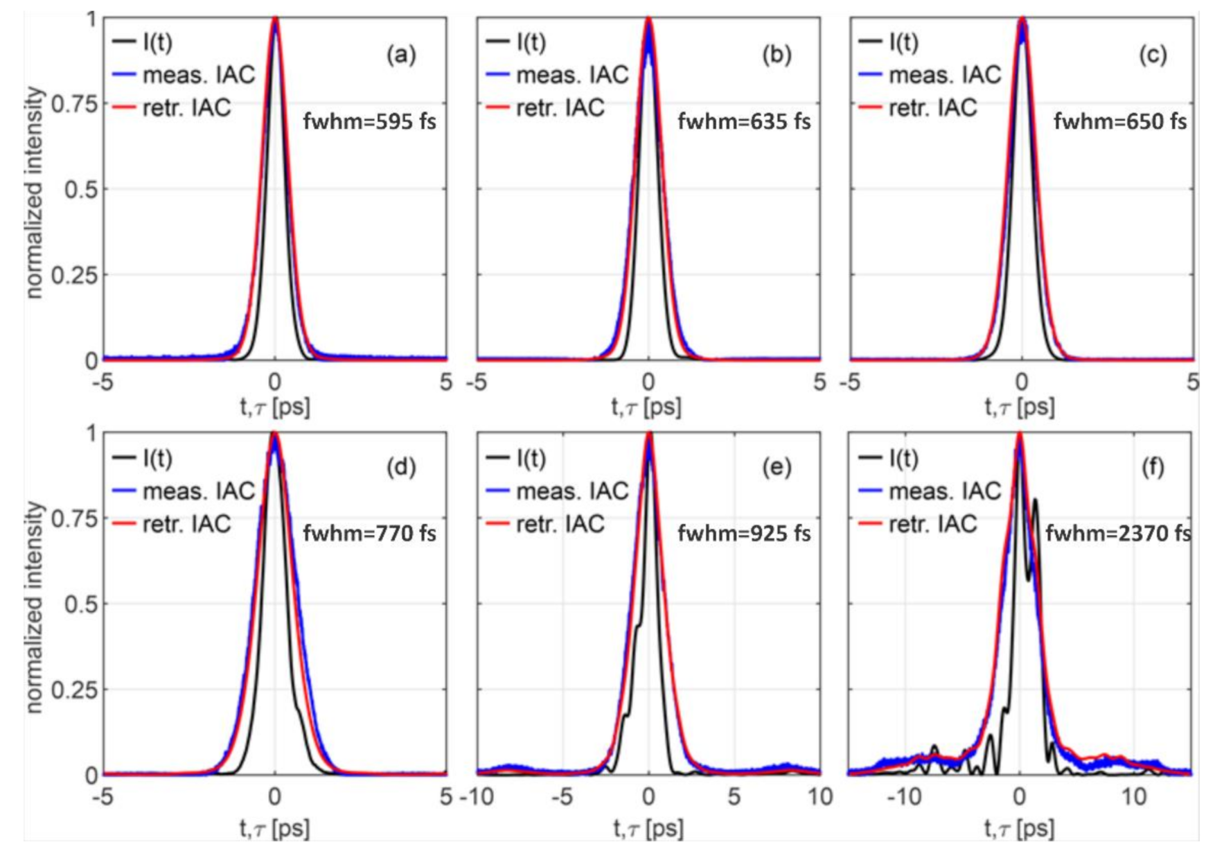
The variations in the accumulated nonlinear phase at different pulse repetition rates influence output pulse parameters. The effect of accumulated nonlinear phase on pulse temporal profile for five different pulse repetition rates is presented in
Figure 2. The figure shows a comparison of pulse temporal profiles for pulses with 50 µJ energy and 100 kHz, 500 kHz, 1 MHz, 1.5 MHz and 2 MHz pulse repetition rates. The reference pulse temporal profile at low-pulse energy of 1 µJ pulse energy and 30 MHz pulse repetition rate is also presented for comparison. Each subfigure shows retrieved pulse intensity from FROG measurement along with retrieved pulse autocorrelation and independently measured autocorrelation with intensity autocorrelator. The comparison between retrieved and measured autocorrelation shows good agreement, which confirms the accuracy of the retrieved pulse intensity. From the presented measurements, we can see that, with increasing pulse repetition rate, pulse temporal duration increases and that the pulse intensity becomes more and more structured with repetition frequencies above 1 MHz.
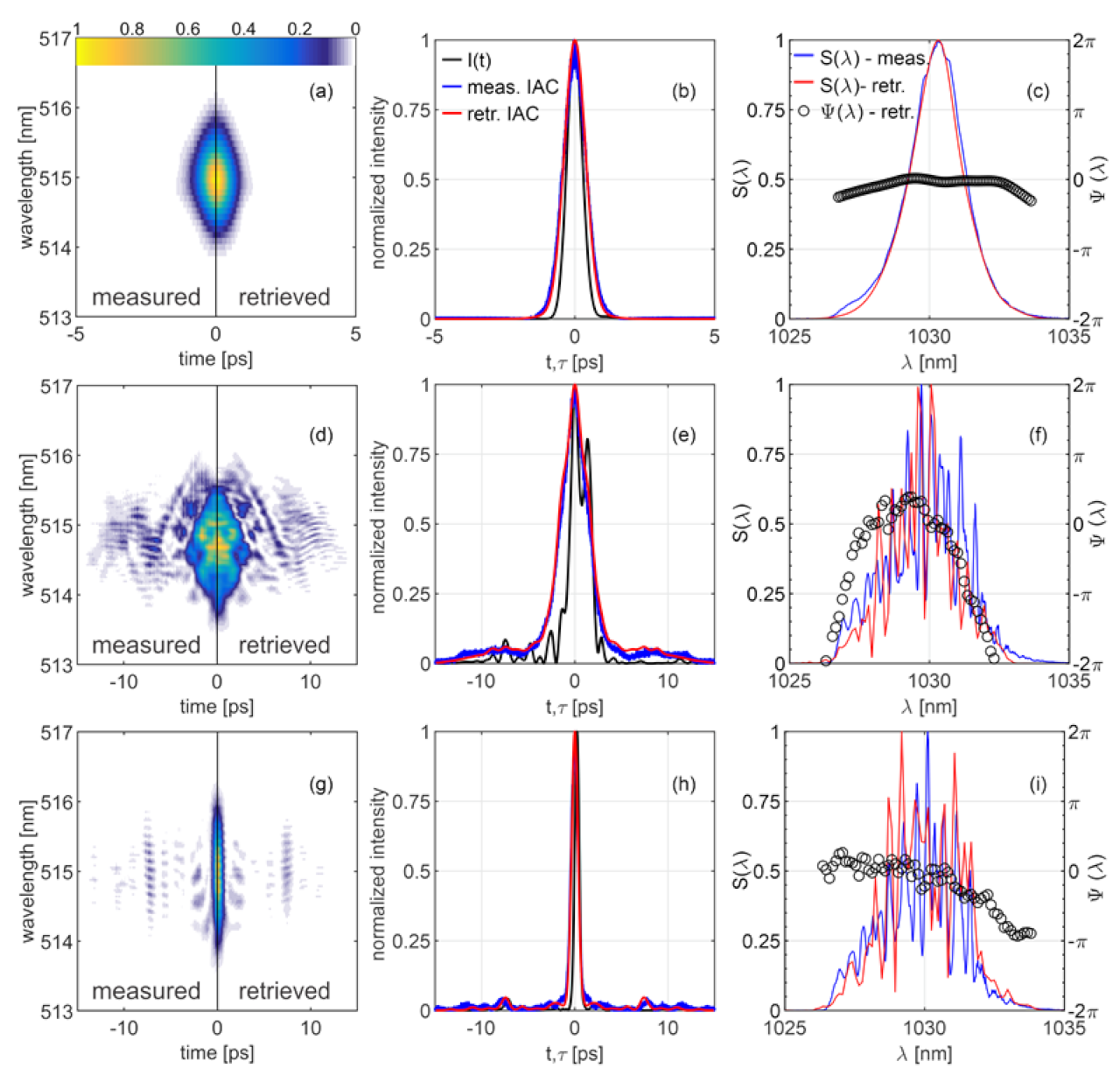
A detailed comparison is shown in
Figure 3 for two limiting cases. In the top line (
Figure 3a–c) is a measurement at 100 kHz, where almost no nonlinear phase is acquired in the fiber amplifier due to the lower gain (35dB). In the center line (
Figure 3d–f) is a measurement at 2 MHz where higher gain must be achieved already in the fiber amplifier (45 dB) in order to achieve the desired output pulse energy from the hybrid laser. The pulse energy from the fiber amplifier is therefore different at 100 kHz case and 2 MHz case and corresponds to 4 µJ and 40 µJ, respectively. This increase in gain results in increased B-integral at higher repetition rates and for selected cases corresponds to 0.25π and 4.2π at 100 kHz and 2 MHz, respectively. The gain in the fiber amplifiers is increased by increasing the pump power of the fiber amplifiers (at low repetition rates, the fiber amplifiers are not pumped with maximum available pump power). From these results, we can see severe deterioration of pulse temporal (
Figure 3e) and spectral shape (
Figure 3f) at 2 MHz compared to 100 kHz pulse repetition rate. The deterioration of the pulse quality is also evident from the FROG measurement (
Figure 3d). In addition to the retrieved pulse intensity and spectrum, a measured autocorrelation and spectrum are also plotted for comparison, showing a good agreement with the retrieved results from FROG measurement. This, along with small FROG error (~1 %), confirms the accuracy of the retrieved results.
Although the pulse shape deteriorates with increasing pulse repetition rate, due to larger gain and consequently higher B-integral in the fiber amplifiers, we can to some extent compensate for the increase in B-integral with tunable chirped fiber Bragg grating that is also used as a pulse stretcher. The compensation is achieved by changing the CFBG dispersion parameters, allowing for compensation of second- and third-order nonlinear phases. As can be seen from
Figure 3f, the dominant contribution of increased B-integral to the spectral phase is of the second order. However, we can see some additional higher order fluctuations in the spectral phase. These higher order contributions cannot be completely compensated for with the use of the TCFBG. Nevertheless, we can significantly improve pulse duration and Strehl ratio. The results after compensation for the case of 2 MHz pulse repetition rate are shown in the bottom row (
Figure 3g–i). The dispersion parameters of the TCFBG in top (
Figure 3a–c) and center row (
Figure 3d–f) are the same as in the reference case at low-pulse energies, where nonlinear effects are negligible, whereas the TCFBG parameters are adjusted in the measurement shown in the bottom row (
Figure 3g–i). From results presented in
Figure 3, we can see that the pulse duration after compensation is significantly shorter (570 fs) than the non-compensated case (2.4 ps). The same can be said for Strehl ratio, where the Strehl ratio after compensation is 0.7 compared to 0.2 before compensation of the nonlinear phase. Although we can significantly improve pulse duration and Strehl ratio with nonlinear phase compensation with TCFBG, we can still see in
Figure 3h that we have some broad pedestal left in the pulse temporal profile. This pedestal is a consequence of non-compensated higher order contributions to the pulse phase.
The results presented in
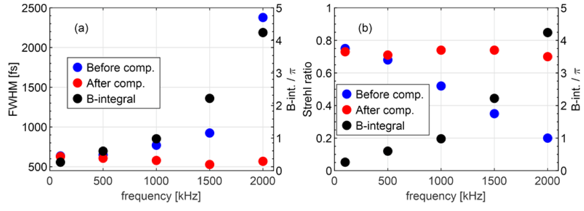
Figure 3 are only for two selected cases (100 kHz and 2 MHz pulse repetition rates). However, the main benefit of a tunable phase compensator is that we can compensate for different amounts of accumulated nonlinear phase. In other words, we can significantly improve laser pulse parameters over a broad range of repetition frequencies. The results at all repetition frequencies are shown in
Figure 4. From results in
Figure 4a, we can see that, with increasing B-integral (black circles), the pulse duration (blue circles) increases if we do not compensate the accumulated nonlinear phase. However, with appropriate adjustment of the TCFBG dispersion parameters we can efficiently compensate for the accumulated nonlinear phase and achieve almost constant pulse duration (red circles) regardless of the value of B-integral.
Similar conclusion can be made from results shown in
Figure 4b, where a decrease in Strehl ratio (blue circles) can be seen with increasing B-integral (black circles). The Strehl ratio is a measure of pulse quality and is defined as the ratio of the peak power of the measured pulse and of the transform limited pulse obtained from the measured spectrum. Therefore, we can see that pulse quality severely deteriorates with increasing B-integral and, what is more, to a different extent depending on the B-integral. However, similar to pulse duration, the Strehl ratio can also be improved by appropriate compensation of the nonlinear phase. The results achieved with compensated nonlinear phase are presented as red circles, where we can see that we can achieve approximately the same Strehl ratio regardless of the accumulated B-integral.
From the herein-presented measurements, it is evident that variations in the output pulse quality and pulse duration were eliminated up to accumulated nonlinear phase of ~4.5π. This is still a conservative estimation as the nonlinear refractive index used in the calculations of B-integral was , which is on the lower edge of the values occurring in the literature for silica fibers. Nevertheless, we expect that further increase in B-integral would result in a decrease of an output pulse quality as pulse’s spectral phase becomes highly structured to an extent at which it cannot be pre-compensated with a given TCFBG.
5. Conclusions
In the presented manuscript, a necessity for a tunable pre-compensation of SPM-induced nonlinear phase in an ultrafast hybrid laser system operating at variable pulse repetition rates was demonstrated. The need for tunable compensation of the nonlinear phase arises from the fact that the gain of the solid-state amplifier decreases as the input laser power to the amplifier increases. The gain shortfall must therefore be compensated for with the fiber pre-amplifier. This means that we must achieve higher gain in fiber pre-amplifier at higher pulse repetition frequencies compared to the gain at lower pulse repetition frequencies, since the overall gain of the hybrid laser must be constant in order to achieve constant output pulse energies. Higher gain consequently increases the accumulated nonlinear phase in the fiber amplifiers. Variations in the accumulated nonlinear phase result in variations of the laser pulse parameters such as pulse duration and Strehl ratio. In this manuscript, we successfully demonstrated that these variations can be compensated for by adjusting the dispersion parameters of a tunable CFBG, which is also used as a pulse stretcher in a CPA scheme. The use of a pulse stretcher for nonlinear phase compensation eliminates the need for additional pulse-shaping components, which significantly simplifies the design. We have demonstrated that with this technique, a nonlinear phase can be compensated for to a different extent depending on the selected pulse repetition rate. In this work, we successfully compensated for accumulated nonlinear phase up to 4.5π, resulting in high-quality ultrashort laser pulses with less than 600 fs pulse duration and Strehl ratio higher than 0.7.
Supplementary Materials
The following are available online at
https://www.mdpi.com/article/10.3390/photonics8090387/s1, Video S1: The supplementary video shows the temporal evolution of the pulse shape, measured with an autocorrelator. At time 0° s, the user sets a new temperature profile or new dispersion values to the TCFBG. In the presented case, the value of the second order dispersion is changed from 49.6
to 48
.
Author Contributions
Conceptualization, R.P., J.P. and L.Č.; software, J.P.; validation, L.Č., J.P. and R.P.; data curation, L.Č.; writing—original draft preparation, L.Č.; writing—review and editing, L.Č., J.P. and R.P.; supervision, R.P.; project administration, R.P.; funding acquisition, R.P.; All authors have read and agreed to the published version of the manuscript.
Funding
This research was funded by [Slovenian Research Agency] grant number [P2-0270] and [L2-9240].
Institutional Review Board Statement
Not applicable.
Informed Consent Statement
Not applicable.
Conflicts of Interest
The authors declare no conflict of interest.
References
- Kalayciog, H.; Elahi, P.; Akcaalan, O.; Ilday, F.O. High-Repetition-Rate Ultrafast Fiber Lasers for Material Processing. IEEE J. Sel. Top. Quantum Electron. 2018, 24, 8800312. [Google Scholar] [CrossRef]
- Ponkratova, E.; Ageev, E.; Komissarenko, F.; Koromyslov, S.; Kudryashov, D.; Mukhin, I.; Veiko, V.; Kuchmizhak, A.; Zuev, D. Femtosecond Laser Fabrication of Hybrid Metal-Dielectric Structures with Nonlinear Photoluminescence. Photonics 2021, 8, 121. [Google Scholar] [CrossRef]
- Shah, L.; Fermann, M.E.; Dawson, J.W.; Barty, C.P.J. Micromachining with a 50 W, 50 ΜJ, Sub-Picosecond Fiber Laser System. Opt. Express OE 2006, 14, 12546–12551. [Google Scholar] [CrossRef] [PubMed]
- Dogan, Y.; Madsen, C.K. Optimization of Ultrafast Laser Parameters for 3D Micromachining of Fused Silica. Opt. Laser Technol. 2020, 123, 105933. [Google Scholar] [CrossRef]
- Volpe, A.; Trotta, G.; Krishnan, U.; Ancona, A. Prediction Model of the Depth of the Femtosecond Laser Micro-Milling of PMMA. Opt. Laser Technol. 2019, 120, 105713. [Google Scholar] [CrossRef]
- Guo, Q.; Zheng, Z.; Wang, B.; Pan, X.; Liu, S.; Tian, Z.; Chen, C.; Yu, Y. Femtosecond Laser Fabricated Apodized Fiber Bragg Gratings Based on Energy Regulation. Photonics 2021, 8, 110. [Google Scholar] [CrossRef]
- Lubatschowski, H. Ultrafast Lasers in Ophthalmology. Phys. Procedia 2010, 5, 637–640. [Google Scholar] [CrossRef] [Green Version]
- Squier, J.; Müller, M. High Resolution Nonlinear Microscopy: A Review of Sources and Methods for Achieving Optimal Imaging. Rev. Sci. Instrum. 2001, 72, 2855–2867. [Google Scholar] [CrossRef]
- Rehbinder, J.; Brückner, L.; Wipfler, A.; Buckup, T.; Motzkus, M. Multimodal Nonlinear Optical Microscopy with Shaped 10 Fs Pulses. Opt. Express OE 2014, 22, 28790–28797. [Google Scholar] [CrossRef]
- Fu, W.; Wright, L.G.; Sidorenko, P.; Backus, S.; Wise, F.W. Several New Directions for Ultrafast Fiber Lasers [Invited]. Opt. Express OE 2018, 26, 9432–9463. [Google Scholar] [CrossRef] [PubMed]
- Jiang, H.; Gong, C.; Nishimura, T.; Murakami, H.; Kawayama, I.; Nakanishi, H.; Tonouchi, M. Terahertz Emission Spectroscopy and Microscopy on Ultrawide Bandgap Semiconductor β-Ga2O3. Photonics 2020, 7, 73. [Google Scholar] [CrossRef]
- Černe, L.; Šušnjar, P.; Petkovšek, R. Compensation of Optical Nonlinearities in a Femtosecond Laser System in a Broad Operation Regime. Opt. Laser Technol. 2021, 135, 106706. [Google Scholar] [CrossRef]
- Chong, A.; Kuznetsova, L.; Wise, F.W. Theoretical Optimization of Nonlinear Chirped-Pulse Fiber Amplifiers. J. Opt. Soc. Am. B JOSAB 2007, 24, 1815–1823. [Google Scholar] [CrossRef]
- Klenke, A.; Müller, M.; Stark, H.; Kienel, M.; Jauregui, C.; Tünnermann, A.; Limpert, J. Coherent Beam Combination of Ultrafast Fiber Lasers. IEEE J. Sel. Top. Quantum Electron. 2018, 24, 1–9. [Google Scholar] [CrossRef]
- Roberts, L.E.; Ward, R.L.; Smith, C.; Shaddock, D.A. Coherent Beam Combining Using an Internally Sensed Optical Phased Array of Frequency-Offset Phase Locked Lasers. Photonics 2020, 7, 118. [Google Scholar] [CrossRef]
- Zaouter, Y.; Guichard, F.; Daniault, L.; Hanna, M.; Morin, F.; Hönninger, C.; Mottay, E.; Druon, F.; Georges, P. Femtosecond Fiber Chirped- and Divided-Pulse Amplification System. Opt. Lett. OL 2013, 38, 106–108. [Google Scholar] [CrossRef]
- Albrodt, P.; Niemeyer, M.; Crump, P.; Hamperl, J.; Moron, F.; Georges, P.; Lucas-Leclin, G. Coherent Beam Combining of High Power Quasi Continuous Wave Tapered Amplifiers. Opt. Express OE 2019, 27, 27891–27901. [Google Scholar] [CrossRef]
- Albrodt, P.; Jamal, M.T.; Hansen, A.K.; Jensen, O.B.; Blume, G.; Paschke, K.; Crump, P.; Georges, P.; Lucas-Leclin, G. Coherent Combining of High Brightness Tapered Amplifiers for Efficient Non-Linear Conversion. Opt. Express OE 2019, 27, 928–937. [Google Scholar] [CrossRef]
- Steinkopff, A.; Jauregui, C.; Stutzki, F.; Nold, J.; Hupel, C.; Haarlammert, N.; Bierlich, J.; Tünnermann, A.; Limpert, J. Transverse Single-Mode Operation in a Passive Large Pitch Fiber with More than 200 Μm Mode-Field Diameter. Opt. Lett. OL 2019, 44, 650–653. [Google Scholar] [CrossRef]
- Stutzki, F.; Jansen, F.; Otto, H.-J.; Jauregui, C.; Limpert, J.; Tünnermann, A. Designing Advanced Very-Large-Mode-Area Fibers for Power Scaling of Fiber-Laser Systems. Optica 2014, 1, 233–242. [Google Scholar] [CrossRef]
- Li, F.; Yang, Z.; Lv, Z.; Duan, Y.; Wang, N.; Yang, Y.; Li, Q.; Yang, X.; Wang, Y.; Zhao, W. Hybrid CPA System Comprised by Fiber-Silicate Glass Fiber-Single Crystal Fiber with Femtosecond Laser Power More than 90 W at 1 MHz. Opt. Laser Technol. 2020, 129, 106291. [Google Scholar] [CrossRef]
- Černe, L.; Petelin, J.; Petkovšek, R. Femtosecond CPA Hybrid Laser System with Pulse-on-Demand Operation. Opt. Express OE 2020, 28, 7875–7888. [Google Scholar] [CrossRef] [PubMed]
- Wang, N.N.; Wang, X.L.; Hu, X.H.; Zhang, T.; Yuan, H.; Zhang, W.; Li, F.; Wang, Y.S.; Zhao, W. 41.8 W Output Power, 200 KHz Repetition Rate Ultra-Fast Laser Based on Yb:YAG Single Crystal Fiber(SCF)Amplifier. Opt. Laser Technol. 2020, 127, 106202. [Google Scholar] [CrossRef]
- Liu, W.; Schimpf, D.N.; Eidam, T.; Limpert, J.; Tünnermann, A.; Kärtner, F.X.; Chang, G. Pre-Chirp Managed Nonlinear Amplification in Fibers Delivering 100 W, 60 Fs Pulses. Opt. Lett. 2015, 40, 151. [Google Scholar] [CrossRef] [PubMed]
- Prawiharjo, J.; Daga, N.K.; Geng, R.; Price, J.H.V.; Hanna, D.C.; Richardson, D.J.; Shepherd, D.P. High Fidelity Femtosecond Pulses from an Ultrafast Fiber Laser System via Adaptive Amplitude and Phase Pre-Shaping. Opt. Express OE 2008, 16, 15074–15089. [Google Scholar] [CrossRef] [Green Version]
- He, F.; Hung, H.S.S.; Price, J.H.V.; Daga, N.K.; Naz, N.; Prawiharjo, J.; Hanna, D.C.; Shepherd, D.P.; Richardson, D.J.; Dawson, J.W.; et al. High Energy Femtosecond Fiber Chirped Pulse Amplification System with Adaptive Phase Control. Opt. Express OE 2008, 16, 5813–5821. [Google Scholar] [CrossRef] [PubMed]
- Nguyen, D.; Piracha, M.U.; Delfyett, P.J. Transform-Limited Pulses for Chirped-Pulse Amplification Systems Utilizing an Active Feedback Pulse Shaping Technique Enabling Five Time Increase in Peak Power. Opt. Lett. OL 2012, 37, 4913–4915. [Google Scholar] [CrossRef]
- Niu, J.; Liu, B.; Song, H.; Zhao, S.; Li, S.; Gu, X.; Hu, M. High-Pulse-Quality Yb-Fiber Amplifier Generation of 10 ΜJ, 250 Fs Pulses at 500 KHz Repetition Rate. Optik 2020, 200, 163399. [Google Scholar] [CrossRef]
- Želudevičius, J.; Danilevičius, R.; Regelskis, K. Optimization of Pulse Compression in a Fiber Chirped Pulse Amplification System by Adjusting Dispersion Parameters of a Temperature-Tuned Chirped Fiber Bragg Grating Stretcher. J. Opt. Soc. Am. B JOSAB 2015, 32, 812–817. [Google Scholar] [CrossRef]
- Veselis, L.; Bartulevicius, T.; Madeikis, K.; Michailovas, A.; Rusteika, N. Compact 20 W Femtosecond Laser System Based on Fiber Laser Seeder, Yb:YAG Rod Amplifier and Chirped Volume Bragg Grating Compressor. Opt. Express OE 2018, 26, 31873–31879. [Google Scholar] [CrossRef]
- Bartulevicius, T.; Veselis, L.; Madeikis, K.; Michailovas, A.; Rusteika, N. Compact Femtosecond 10 μJ Pulse Energy Fiber Laser with a CFBG Stretcher and CVBG Compressor. Opt. Fiber Technol. 2018, 45, 77–80. [Google Scholar] [CrossRef]
- Bartulevicius, T.; Frankinas, S.; Michailovas, A.; Vasilyeu, R.; Smirnov, V.; Trepanier, F.; Rusteika, N. Compact Fiber CPA System Based on a CFBG Stretcher and CVBG Compressor with Matched Dispersion Profile. Opt. Express 2017, 25, 19856–19862. [Google Scholar] [CrossRef]
- Yusim, A.; Pestov, D.; Ryabtsev, A.; Drozhzhin, A.; Sevian, A.; Jenket, B.; Venus, G.; Barsalou, J.; Antas, J.; Platonov, N.; et al. All-Fiber Pulse Shaper for Adaptive Dispersion Compensation in Industrial Lasers. In Proceedings of the Fiber Lasers and Glass Photonics: Materials through Applications, International Society for Optics and Photonics. Strasbourg, France, 17 May 2018; Volume 10683, p. 106831P. [Google Scholar] [CrossRef]
- Audo, F.; Boscolo, S.; Fatome, J.; Kibler, B.; Finot, C. Nonlinear Spectrum Broadening Cancellation by Sinusoidal Phase Modulation. Opt. Lett. OL 2017, 42, 2902–2905. [Google Scholar] [CrossRef]
- Liu, Y.; Li, W.; Luo, D.; Bai, D.; Wang, C.; Zeng, H. Generation of 33 Fs 93.5 W Average Power Pulses from a Third-Order Dispersion Managed Self-Similar Fiber Amplifier. Opt. Express OE 2016, 24, 10939–10945. [Google Scholar] [CrossRef] [PubMed]
- Ruehl, A.; Marcinkevicius, A.; Fermann, M.E.; Hartl, I. 80 W, 120 Fs Yb-Fiber Frequency Comb. Opt. Lett. OL 2010, 35, 3015–3017. [Google Scholar] [CrossRef] [PubMed]
| Publisher’s Note: MDPI stays neutral with regard to jurisdictional claims in published maps and institutional affiliations. |
© 2021 by the authors. Licensee MDPI, Basel, Switzerland. This article is an open access article distributed under the terms and conditions of the Creative Commons Attribution (CC BY) license (https://creativecommons.org/licenses/by/4.0/).


