All-Fiber Gas Raman Laser by D2-Filled Hollow-Core Photonic Crystal Fibers

Abstract
:1. Introduction
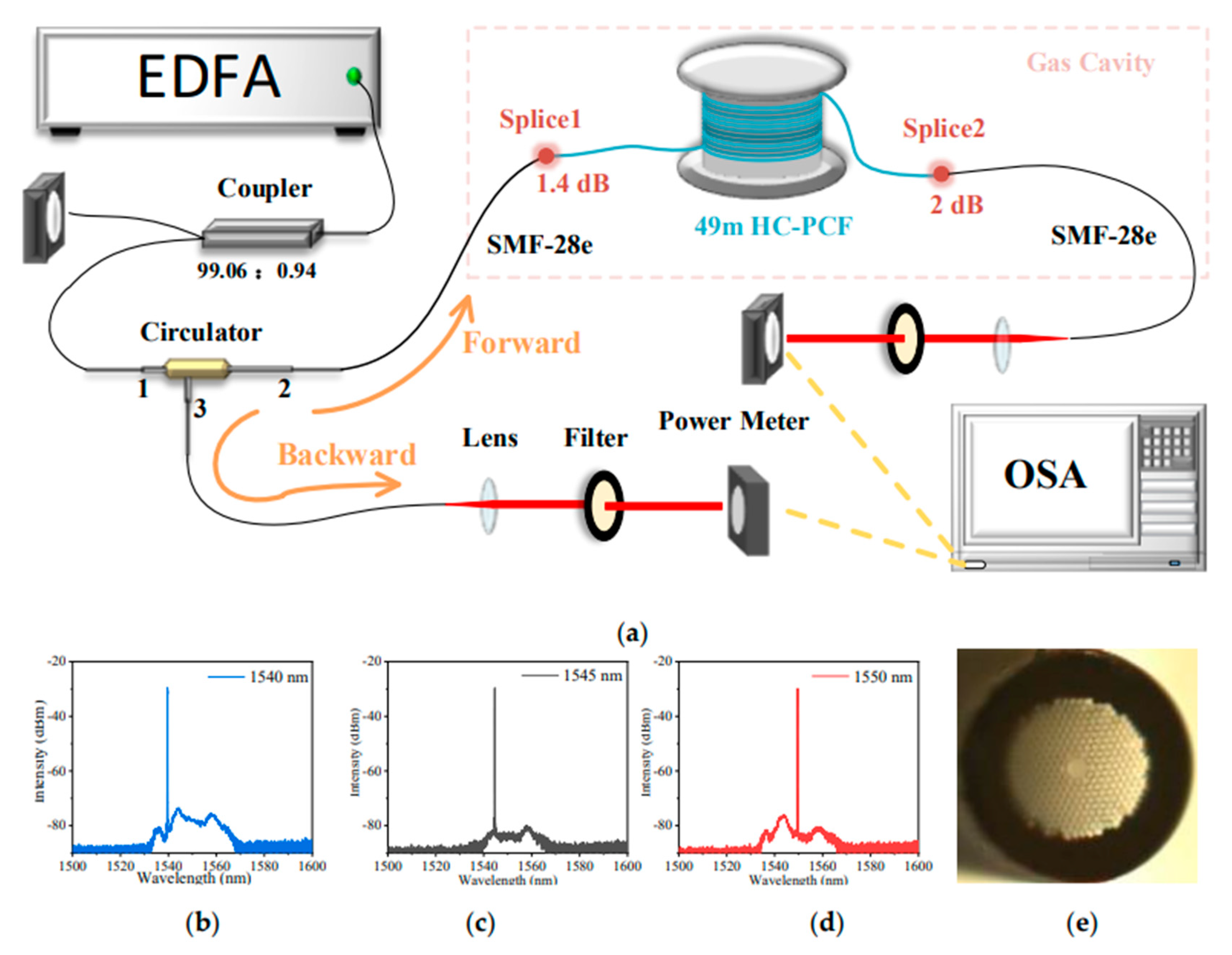
2. Experimental Setup
3. Results and Discussion
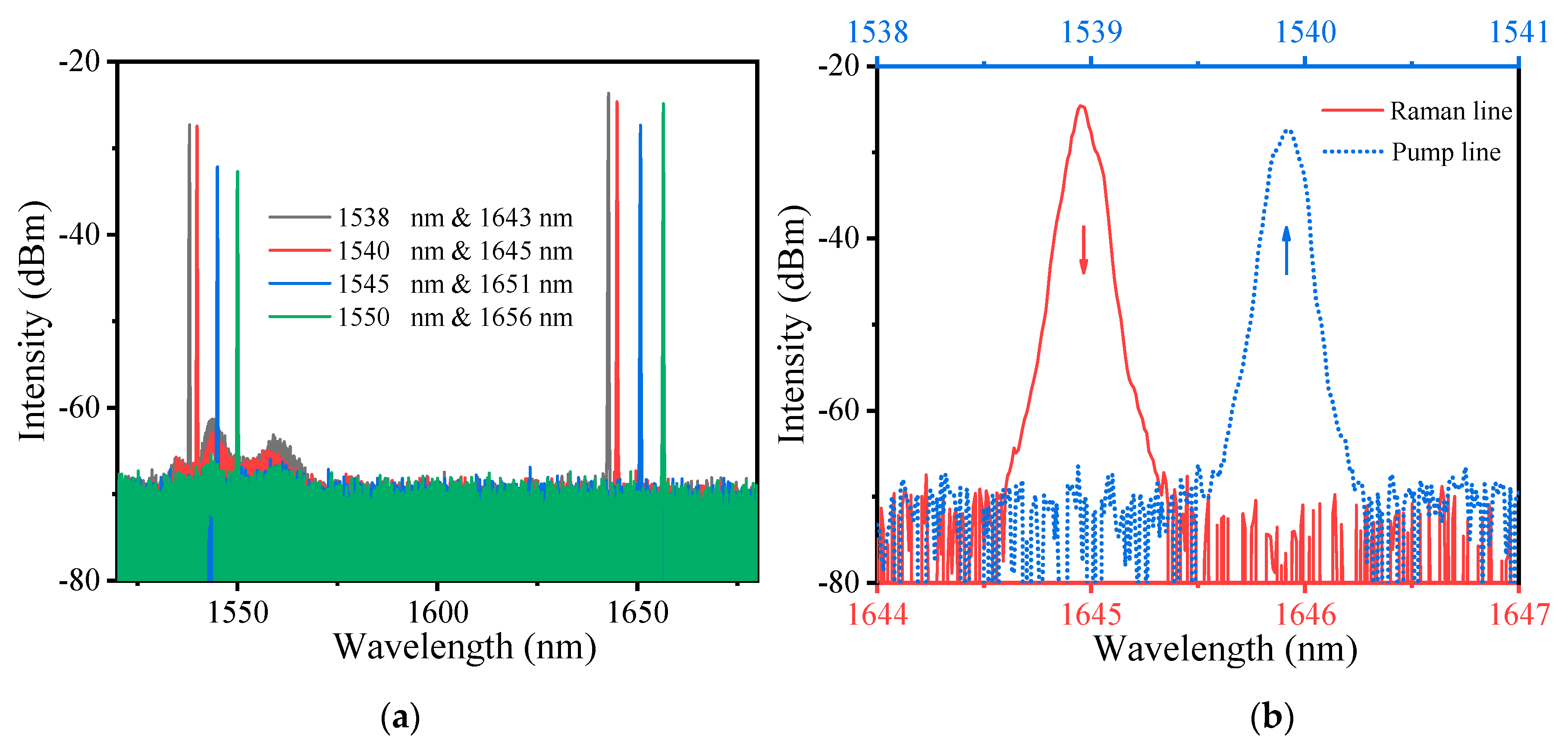
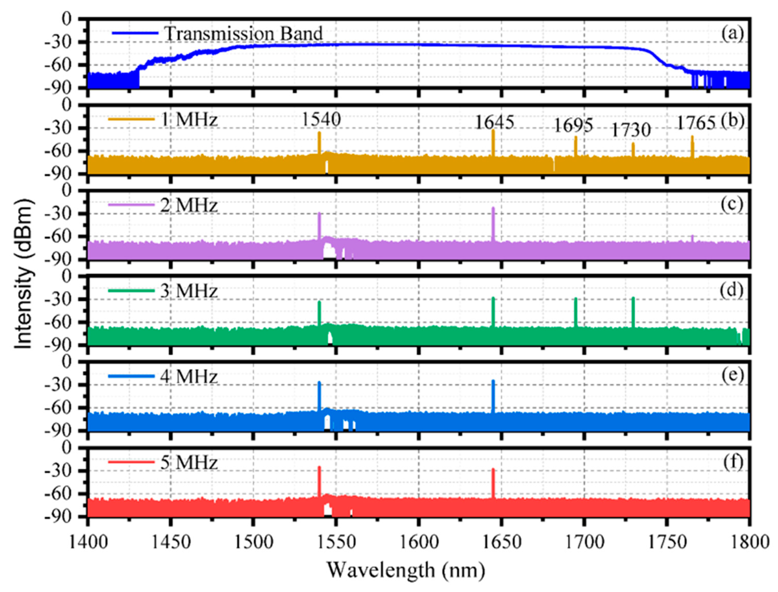
3.1. Spectrum Characteristics
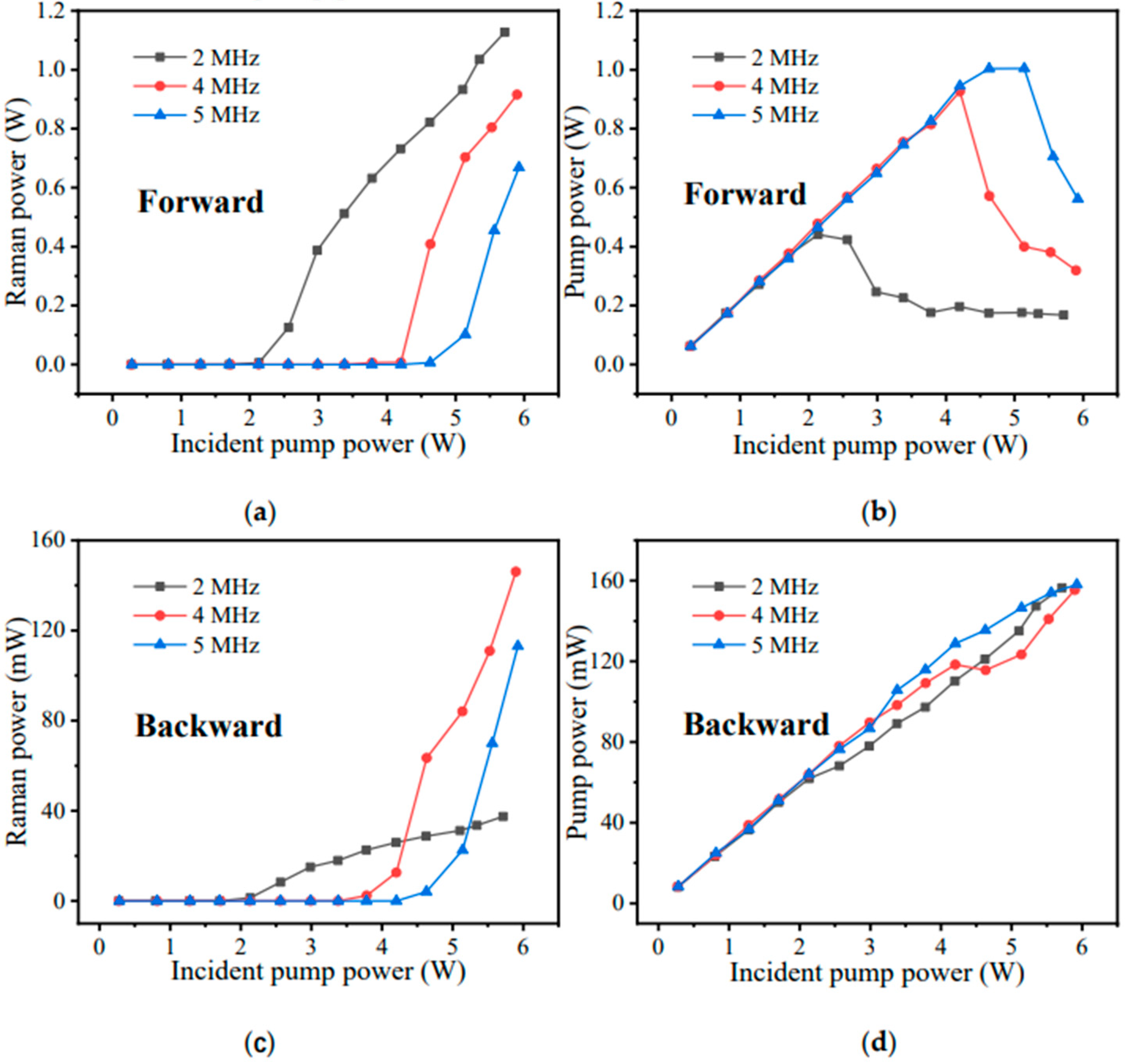
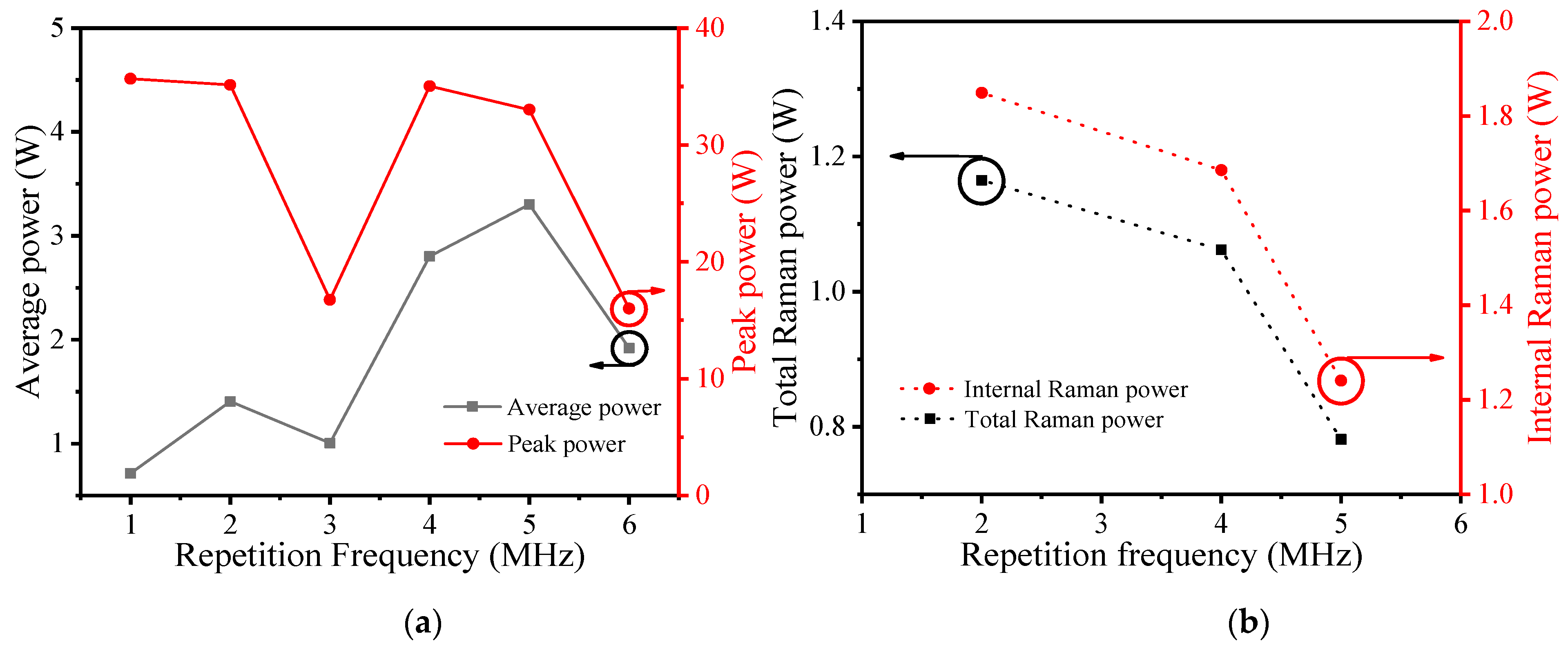
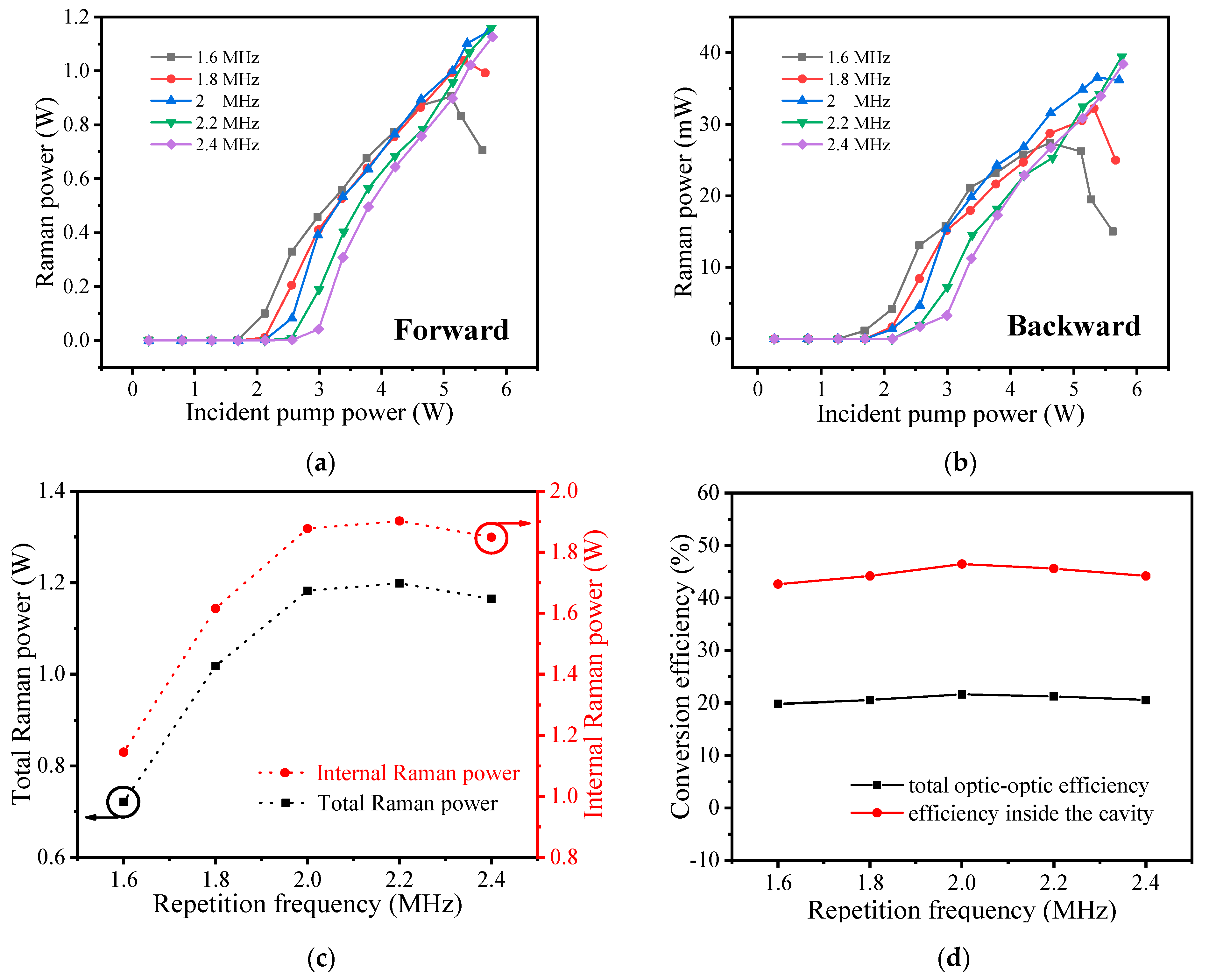
3.2. Power Characteristics
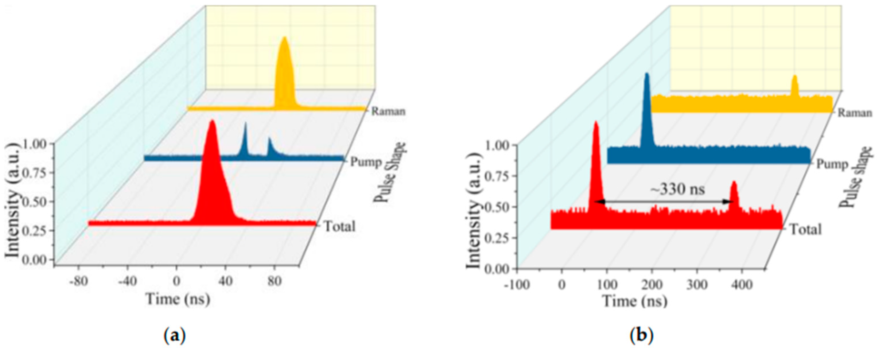
3.3. Pulse Shapes
4. Conclusions
Author Contributions
Funding
Data Availability Statement
Conflicts of Interest
References
- Minck, R.W.; Terhune, R.W.; Rado, W.G. Laser-stimulated Raman Effect and Resonant Four-photon Interactions in gases H2, D2, and CH4. Appl. Phys. Lett. 1963, 3, 181–184. [Google Scholar] [CrossRef]
- Cregan, R.F. Single-Mode Photonic Band Gap Guidance of Light in Air. Science 1999, 285, 1537–1539. [Google Scholar] [CrossRef] [PubMed] [Green Version]
- Benabid, F.; Knight, J.C.; Antonopoulos, G.; Russell, P.S.J. Stimulated Raman Scattering in Hydrogen-Filled Hollow-Core Photonic Crystal Fiber. Science 2002, 298, 399–402. [Google Scholar] [CrossRef] [PubMed]
- Benabid, F.; Bouwmans, G.; Knight, J.C.; Russell, P.S.J.; Couny, F. Ultrahigh Efficiency Laser Wavelength Conversion in a Gas-Filled Hollow Core Photonic Crystal Fiber by Pure Stimulated Rotational Raman Scattering in Molecular Hydrogen. Phys. Rev. Lett. 2004, 93, 123903. [Google Scholar] [CrossRef] [PubMed]
- Couny, F.; Benabid, F.; Light, P.S. Subwatt Threshold Cw Raman Fiber-Gas Laser Based on H2 -Filled Hollow-Core Photonic Crystal Fiber. Phys. Rev. Lett. 2007, 99, 143903. [Google Scholar] [CrossRef] [PubMed]
- Wang, Z.; Yu, F.; Wadsworth, W.J.; Knight, J.C. Efficient 1.9 μm Emission in H2-Filled Hollow Core Fiber by Pure Stimulated Vibrational Raman Scattering. Laser Phys. Lett. 2014, 11, 105807. [Google Scholar] [CrossRef] [Green Version]
- Li, Z.; Huang, W.; Cui, Y.; Wang, Z. Efficient Mid-Infrared Cascade Raman Source in Methane-Filled Hollow-Core Fibers Operating at 2.8 μm. Opt. Lett. 2018, 43, 4671. [Google Scholar] [CrossRef] [PubMed]
- Zhang, Y.; Zhang, P.; Liu, P.; Han, K.; Du, Q.; Wang, T.; Zhang, L.; Tong, S.; Jiang, H. Fiber Light Source at 1.7 μm Waveband and Its Applications. Laser Optoelectron. Prog. 2016, 53, 090002. [Google Scholar] [CrossRef]
- Piao, Z.; Ma, T.; Li, J.; Wiedmann, M.T.; Huang, S.; Yu, M.; Kirk Shung, K.; Zhou, Q.; Kim, C.-S.; Chen, Z. High Speed Intravascular Photoacoustic Imaging with Fast Optical Parametric Oscillator Laser at 1.7 Μm. Appl. Phys. Lett. 2015, 107, 083701. [Google Scholar] [CrossRef] [PubMed] [Green Version]
- Alexander, V.V.; Ke, K.; Xu, Z.; Islam, M.N.; Freeman, M.J.; Pitt, B.; Welsh, M.J.; Orringer, J.S. Photothermolysis of Sebaceous Glands in Human Skin Ex Vivo with a 1708 nm Raman Fiber Laser and Contact Cooling: PHOTOTHERMOLYSIS OF SE-BACEOUS GLANDS. Lasers Surg. Med. 2011, 43, 470–480. [Google Scholar] [CrossRef] [PubMed] [Green Version]
- Mingareev, I.; Weirauch, F.; Olowinsky, A.; Shah, L.; Kadwani, P.; Richardson, M. Welding of Polymers Using a 2 μm Thulium Fiber Laser. Opt. Laser Technol. 2012, 44, 2095–2099. [Google Scholar] [CrossRef]
- Quimby, R.S.; Shaw, L.B.; Sanghera, J.S.; Aggarwal, I.D. Modeling of Cascade Lasing in Dy: Chalcogenide Glass Fiber Laser with Efficient Output at 4.5 μm. IEEE Photon. Technol. Lett. 2008, 20, 123–125. [Google Scholar] [CrossRef]
- Huang, W.; Li, Z.; Cui, Y.; Zhou, Z.; Wang, Z. Efficient, Watt-Level, Tunable 1.7 μm Fiber Raman Laser in H2-Filled Hollow-Core Fibers. Opt. Lett. 2020, 45, 475–478. [Google Scholar] [CrossRef]
- Li, H.; Pei, W.; Huang, W.; Wang, M.; Wang, Z. Highly Efficient Nanosecond 1.7 μm Fiber Gas Raman Laser by H2-Filled Hollow-Core Photonic Crystal Fibers. Crystals 2020, 11, 32. [Google Scholar] [CrossRef]
- Pei, W.; Li, H.; Huang, W.; Wang, M.; Wang, Z. All-Fiber Tunable Pulsed 1.7 μm Fiber Lasers Based on Stimulated Raman Scattering of Hydrogen Molecules in Hollow-Core Fibers. Molecules 2021, 26, 4561. [Google Scholar] [CrossRef] [PubMed]
- Cui, Y.; Huang, W.; Li, Z.; Zhou, Z.; Wang, Z. High-Efficiency Laser Wavelength Conversion in Deuterium-Filled Hollow-Core Photonic Crystal Fiber by Rotational Stimulated Raman Scattering. Opt. Express 2019, 27, 30396. [Google Scholar] [CrossRef] [PubMed]
- Li, H.; Huang, W.; Cui, Y.; Zhou, Z.; Wang, Z. 3 W Tunable 1.65 μm Fiber Gas Raman Laser in D2-Filled Hollow-Core Photonic Crystal Fibers. Opt. Laser Technol. 2020, 132, 106474. [Google Scholar] [CrossRef]
- Li, H.; Huang, W.; Cui, Y.; Zhou, Z.; Wang, Z. Pure rotational stimulated Raman scattering in H2-filled hollow-core photonic crystal fibers. Opt. Express 2020, 28, 23881. [Google Scholar] [CrossRef] [PubMed]
- Yu, R.; Wang, C.; Benabid, F.; Chiang, K.; Xiao, L. Robust mode matching between structurally dissimilar optical fiber waveguides. ACS Photonics 2021, 8, 857. [Google Scholar] [CrossRef]
- Wang, C.; Yu, R.; Debord, B.; Gerome, F.; Benabid, F.; Chiang, K.; Xiao, L. Ultralow-loss fusion splicing between negative curvature hollow-core fibers and conventional SMFs with a reverse-tapering method. Opt. Express 2021, 29, 22470. [Google Scholar] [CrossRef] [PubMed]


Publisher’s Note: MDPI stays neutral with regard to jurisdictional claims in published maps and institutional affiliations. |
© 2021 by the authors. Licensee MDPI, Basel, Switzerland. This article is an open access article distributed under the terms and conditions of the Creative Commons Attribution (CC BY) license (https://creativecommons.org/licenses/by/4.0/).
Share and Cite
Pei, W.; Li, H.; Huang, W.; Wang, M.; Wang, Z. All-Fiber Gas Raman Laser by D2-Filled Hollow-Core Photonic Crystal Fibers. Photonics 2021, 8, 382. https://doi.org/10.3390/photonics8090382
Pei W, Li H, Huang W, Wang M, Wang Z. All-Fiber Gas Raman Laser by D2-Filled Hollow-Core Photonic Crystal Fibers. Photonics. 2021; 8(9):382. https://doi.org/10.3390/photonics8090382
Chicago/Turabian StylePei, Wenxi, Hao Li, Wei Huang, Meng Wang, and Zefeng Wang. 2021. "All-Fiber Gas Raman Laser by D2-Filled Hollow-Core Photonic Crystal Fibers" Photonics 8, no. 9: 382. https://doi.org/10.3390/photonics8090382