Communication

Highly Efficient Double-Layer Diffraction Microstructures Based on New Plastics and Molded Glasses

by
Grigoriy I. Greisukh
1,*,
Viktor A. Danilov
2,
Evgeniy G. Ezhov
1,
Sergey V. Kazin
1 and
Boris A. Usievich
3
1
Physics Department of Penza State University of Architecture and Construction, G. Titova Str., 440028 Penza, Russia
2
Scientific and Technological Center for Unique Instrumentation of the Russian Academy of Sciences, Butlerova Str., 117342 Moscow, Russia
3
Prokhorov General Physics Institute of the Russian Academy of Sciences, Vavilov Str., 119991 Moscow, Russia
*
Author to whom correspondence should be addressed.
Photonics 2021, 8(8), 327; https://doi.org/10.3390/photonics8080327
Submission received: 8 July 2021 / Revised: 3 August 2021 / Accepted: 9 August 2021 / Published: 11 August 2021
(This article belongs to the Special Issue Polarized Light and Optical Systems)

Abstract

:
Within the framework of rigorous diffraction theory, the maximum possible incidence angles of radiation on two-layer sawtooth relief-phase microstructures in the visible (0.4 ≤ λ ≤ 0.7 μm) spectral range are compared. Optical materials for the layers of these microstructures are selected from a database of 47 plastics and 165 molded glasses. It is shown that when the ratio of the spatial period of the microstructure to the effective depth of the relief is greater than 20, the achievable angles within which the diffraction efficiency exceeds 0.95 lie in a wide range from 18.5° to 40.5° for single-relief structures and 7.5° to 22.3° for structures with two internal reliefs. The best results for purely plastic microstructures are obtained when the plastic CMT and the indium tin oxide nanocomposite in polymethylmethacrylate are used.

1. Introduction

Diffractive optical elements (DOEs) are of considerable interest for the design of imaging optical systems for polychromatic radiation owing to their unique aberration properties. Indeed, a single DOE with low optical power, when introduced into a refractive lens objective design, enables a high degree of chromatism correction, which is necessary to obtain high-quality color images [1,2,3,4,5]. This is achieved even with a limited set of optical materials that allow refractive surfaces to be produced by precision stamping [6,7,8]. However, the dependence of the diffraction efficiency (DE) of DOEs on the wavelength and incidence angle of radiation has seriously hindered their widespread practical use in such systems, specifically, the lenses of photography and video cameras in mobile devices and mass video surveillance devices, which are produced using precision stamping of optical plastics.
The number of optical plastics and glasses for molded optics lenses (GMOLs) that enable the replication of optical elements with microstructures on their surfaces by precision molding or stamping has recently expanded significantly. Consequently, we have reconsidered the possibility of creating technological diffractive microstructures with high efficiency for incident polychromatic radiation in given spectral and angular ranges.
In the current paper, we only considered two-layer sawtooth relief-phase microstructures, because, at present, only multilayer sawtooth microstructures can achieve the DE uniformity required in both the spectral and angular ranges. As a result, only such a microstructure enables the use of DOEs in optical imaging systems, and two layers is the minimum number of layers allowed [5,8,9,10,11,12,13].
In this work, we consider only two-layer sawtooth relief-phase microstructures, since at present only multilayer sawtooth microstructures make it possible to achieve the required level of homogeneity both in the required spectral and angular ranges. As a result, only such a microstructure allows the use of DO in optical imaging systems, and two layers is the minimum allowable number of layers [5,8,9,10,11,12,13].

2. Research Method

The dependence of the DE on the angle of incidence and wavelength was estimated within the framework of rigorous diffraction theory by solving a system of Maxwell equations with appropriate boundary conditions using rigorous coupled-wave analysis (RCWA) [14]. We have taken into account that when evaluating by the RCWA method, the modulus of the negative angle of incidence on the microstructure |ψN| and the positive angle of incidence ψP (see Figure 1a) lead to the same decrease in DE. Therefore, we used the smallest corners of |ψN| and ψP as the maximum allowable angle, Ψ, as suggested in [15,16].
In the calculations, we assumed that radiation in the visible spectral range (0.4 ≤ λ ≤ 0.7 μm) falls on the microstructure in air from the side of the medium with refractive index n1(λ) and the angle Ψ is measured from the normal to the substrate.
The assessment of the optimal depth of microstructure relief and the maximum allowable incidence angle of radiation clearly depends on the choice of an appropriate criterion. When an optical element with a diffractive microstructure will be used in a spectral device or imaging optical system in which the diffraction of radiation into side orders is undesirable at any wavelength in the operating spectral range, the criterion proposed in [16] is a good choice. According to this criterion, the depth of relief is considered optimal if it provides the maximum possible range of incidence angles of radiation in the selected spectral range within which the minimum DE does not fall below the minimum permissible value, which is equal to 95% of the maximum DE value at normal incidence (see Equation (1)):
Q = η EM , min ( Ψ ) / η EM , max ( Ψ = 0 ) 0.95
This value ensures not only the absence of a halo, but also the absence of any other visually observable negative effects of side diffraction orders on the quality of the image formed by an optical system with a diffractive element. This criterion has been successfully used in a number of studies (see, for example, [17]). Note that the maximum allowable incidence angle of radiation (i.e., the angle Ψ for which Q ≥ 0.95) depends not only on the microstructure materials, but also on the ratio of its spatial period to the optimal relief depth, P = Λ/hopt.
The optimal relief depth and the maximum limiting angles of incidence of radiation on the microstructure were obtained using the MC Grating computer program [18], which implements the RCWA method.

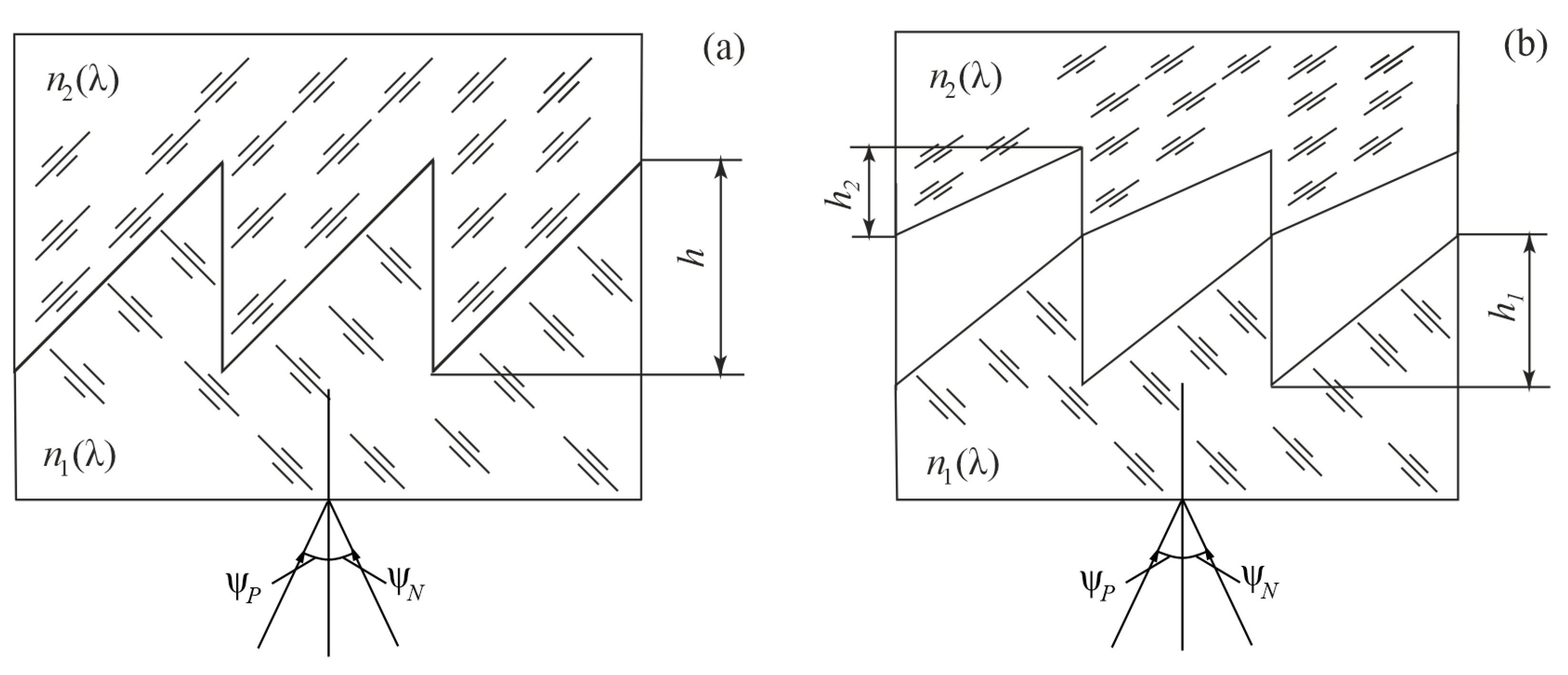
3. Results of the Study of Single-Relief Microstructures

First, we present the results of a study of the sawtooth two-layer single-relief microstructure shown in Figure 1a. Pairs of optical materials for this microstructure were selected from a database that included 47 optical plastics presented in the catalogs ANGSTROMLINK, ZEON, MISC and APEL of the ZEMAX optical design software [19], as well as plastics produced by Mitsubishi Gas Chemical Co. under the Iupizeta trademark [20].
In addition, the database included the optical plastic CMT. We have found information about this material on the internet; unfortunately, however, the link was lost. The wavelength dependence of its refractive index is given by the Schott formula:
n ( λ ) = a 0 + a 1 λ 2 + a 2 λ 2 + a 3 λ 4 + a 4 λ 6 + a 5 λ 8
where a0 = 2.246238620 × 100; a1 = −1.192632600 × 10⁻²; a2 = 1.522135810 × 10⁻²; a3 = 7.359996230 × 10⁻⁴; a4 = −8.768597050 × 10⁻⁶; and a5 = 4.330781690 × 10⁻⁷.
The results are presented in the Table 1 as microstructures No. 2–4. For comparison, No. 1 is the optimal microstructure composed of commercially available materials that we proposed in an earlier work [21]. One of its layers is plastic, and the other is GMOL [22,23]. In addition, Table 1 lists microstructure No. 5, which is composed of nanocomposite plastics [17] developed by D. Werdehausen et al. [24].
The calculated DE dependence on the angle of incidence at various wavelengths for microstructures No. 3 and No. 5 is shown in Figure 2 and Figure 3, respectively. Unlike the SDT method, the calculation of the DE using the RCWA method accounts for Fresnel losses caused by the reflection of radiation off one or two reliefs.
Table 1 and Figure 2 shows that among the pure plastic structures, only that made of CMT affords limiting incidence angles of radiation on the microstructure that are comparable to those of microstructure No. 1. Indeed, the removal of this plastic from the database dramatically degraded the achievable characteristics of the microstructures. Unfortunately, optical plastics with a dispersion formula similar to that of CMT plastics are not included in any commercial catalog and are no longer found on the internet.
The number of glasses that can be used to fabricate diffraction elements by precision molding or stamping has also significantly expanded recently; therefore, after CMT was removed from the database, we replaced it with GMOL glasses. It should be noted here that GMOL glasses are still less viable for manufacturing than plastics.
In the microstructure design, 1 of 47 plastics was selected for one layer, and 1 of 165 glasses was selected for the other layer. The optimal combinations obtained in this way are presented in Table 1 as No. 4. The limiting incidence angles of radiation for this hybrid microstructure are clearly comparable to those of purely plastic microstructures, including those using CMT.
In addition, the limiting incidence angles of radiation of all the microstructures discussed above are worse by at least a factor of two than that of nanocomposite microstructure No. 5. In addition, microstructure No. 5 maintains the limiting angles given in Table 1 even when the spectral range is expanded to 0.8 μm.
It should be emphasized that the results presented above again confirm the well-known requirement for pairs of materials for two-layer single-relief microstructures: the material with the higher refractive index should also have a larger Abbe number [25,26].

4. Results of the Study of Double-Relief Microstructures

For two-layer double-relief microstructures (Figure 1b), the opposite requirement is imposed on the dispersion characteristics of the materials; that is, the material with a higher refractive index should have a lower Abbe number [16]. Consequently, even the most widely used optical plastics, polymethylmethacrylate and polycarbonates, can be used to obtain a microstructure with very good characteristics (No. 1 in Table 2). Please note that for double-relief microstructures, the parameter P is defined as P = Λ / ( h 1 + h 2 ) .
By an extended search of a database including 47 optical plastics, we found an entire group of double-relief microstructures with limiting incidence angles of radiation similar to those of previously investigated microstructures No. 1 and 2. The optimal microstructure from this group, which is characterized by the largest maximum limiting angle, is presented in Table 2 as No. 3. However, the limiting incidence angles of radiation on these microstructures are approximately 1.5 times worse than those of nanocomposite microstructure No. 4. The calculated DE dependence on the angle of incidence at various wavelengths for microstructures No. 3 and No. 4 is shown in Figure 4 and Figure 5, respectively.

5. Discussion

Several papers have been published recently that focused on the DE of diffractive microstructures [5,6,7,8,12,13,27]. However, papers focusing on both the spectral and angular dependence of the DOE within the framework of rigorous diffraction theory are virtually absent, except for our own previous publications [15,16,17,21].
We believe that the results presented in Section 2 and Section 3, due to the RCWA method, reliably describe the currently achievable limiting angular characteristics of two-layer microstructures. These results indicate that all of commercially available today optical plastics do not significantly increase the limiting angular characteristics previously published. Progress can be ensured thanks to new optical plastics, especially nanocomposites, which will open up the possibility of effective use of DOEs in wide-angle optical systems.
Discussing the presented results in more detail one should dwell on two points:
  • Everything we could find about CMT plastic is included in this paper. The abbreviation CMT is also taken from the internet. The dispersion formula of this plastic is almost ideal for a plastic two-layer single-relief microstructure. Moreover, we hope that the developers of this plastic, having read our paper, will receive an additional incentive to continue working on it.
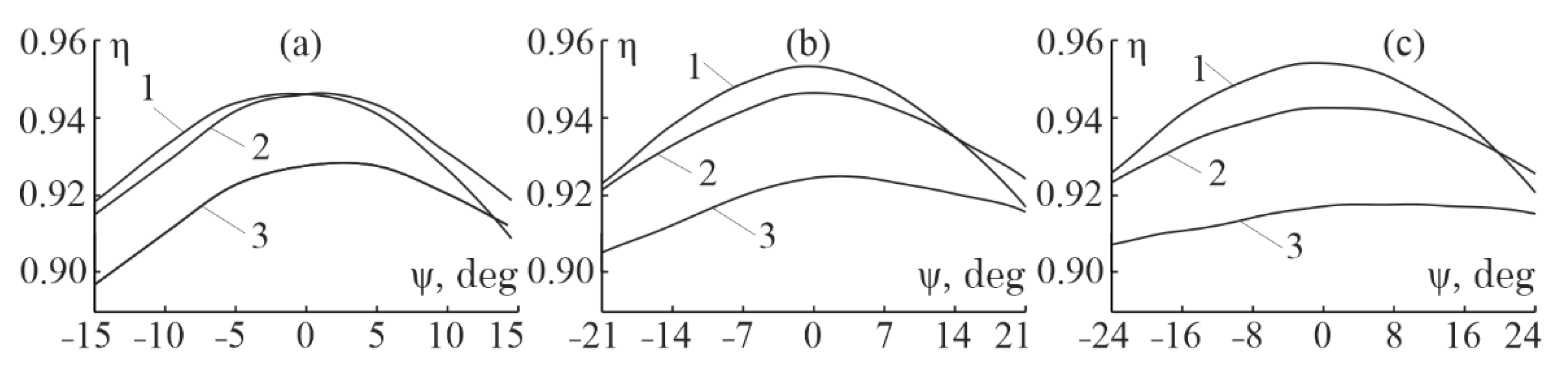
  • As follows from Table 1 and Table 2, in the overwhelming majority of cases, at the same P, the smallest angle Ψ corresponds to microstructures with the greatest relief depth, while the maximum angle of incidence Ψ corresponds to microstructures with the smallest relief depth. One of the reasons for this phenomenon is the screening of radiation by vertical surfaces of the relief at an oblique incidence of radiation. The effect will be greater when the relief is deeper, and this will lead to a smaller maximum allowable angle Ψ.
It should be noted that various ways of accounting for the effect of screening due to the real depth of relief have been proposed even within the framework of the scalar theory of diffraction [27]. However, even in this case, the reliability of scalar results is significantly inferior to the results obtained using the framework of the rigorous theory of diffraction.

6. Conclusions

Let us summarize the main results of the study. An increase in the number of commercially available optical plastics did not provide new possibilities for the design of two-layer single-relief microstructures for polychromatic radiation in the visible range. However, the situation could change dramatically when plastics with a dispersion formula similar to that of CMT appear on the market. In this case optical elements suitable for mobile devices and video surveillance devices will be supplemented by DOEs with three types of microstructures: purely plastic single-relief and double-relief structures and hybrid single-relief microstructure composed of plastic and glass. Finally, the development of industrial production of nanocomposite optical plastics will open the possibility of the effective use of these diffractive elements in wide-angle optical systems.

Author Contributions

Conceptualization, G.I.G. and E.G.E.; methodology, G.I.G. and V.A.D.; software, S.V.K.; investigation, G.I.G.; resources, V.A.D.; writing—original draft preparation, G.I.G. and B.A.U.; writing—review and editing, G.I.G. and B.A.U.; visualization, S.V.K.; project administration G.I.G. All authors have read and agreed to the published version of the manuscript.

Funding

This research was funded by the Russian Science Foundation (Project No. 20-19-00081).

Institutional Review Board Statement

Not applicable.

Informed Consent Statement

Not applicable.

Data Availability Statement

To exclude this statement.

Acknowledgments

The authors are grateful to the authors of paper [24] for the possibility of using the dispersion formulae for their nanocomposite materials.

Conflicts of Interest

The authors declare no conflict of interest. The funders had no role in the design of the study; in the collection, analyses, or interpretation of data; in the writing of the manuscript, or in the decision to publish the results.

References

  1. Flores, A. Achromatic hybrid refractive-diffractive lens with extended depth of focus. Appl. Opt. 2004, 43, 5618–5630. [Google Scholar] [CrossRef] [PubMed]
  2. Greisukh, G.I.; Ezhov, E.G.; Levin, I.A.; Stepanov, S.A. Design of achromatic and apochromatic plastic microobjectives. Appl. Opt. 2010, 49, 4379–4384. [Google Scholar] [CrossRef] [PubMed]
  3. Jia, H. Design of compact projection lenses using double-layered diffractive optical elements. J. Soc. Inf. Disp. 2011, 19, 265–270. [Google Scholar] [CrossRef]
  4. Greisukh, G.I.; Ezhov, E.G.; Kalashnikov, A.V.; Stepanov, S.A. Diffractive-refractive correction units for plastic compact zoom lenses. Appl. Opt. 2012, 51, 4597–4604. [Google Scholar] [CrossRef] [PubMed]
  5. Mao, S.; Zhao, J. Design and analysis of a hybrid optical system containing a multilayer diffractive optical element with improved diffraction efficiency. Appl. Opt. 2020, 59, 5888–5895. [Google Scholar] [CrossRef] [PubMed]
  6. Plastic Hybrid Aspheric Lenses. Available online: http://www.edmundoptics.com/optics/optical-lenses/aspheric-lenses/plastic-hybrid-aspheric-lenses/3200 (accessed on 28 June 2021).
  7. Nakamura, T.; Suzuki, K.; Inokuchi, Y.; Nishimura, S. Fundamental properties of broadband dual-contact diffractive optical elements. Opt. Eng. 2019, 58, 085103. [Google Scholar] [CrossRef]
  8. Yang, H.; Xue, C.; Xiao, J.; Chen, J. Glued diffraction optical elements with broadband and a large field of view. Appl. Opt. 2020, 59, 10217–10223. [Google Scholar] [CrossRef] [PubMed]
  9. Lukin, A.V.; Mustafin, K.S.; Rafikov, R.A. The Hologram Optical. Element. Patent No. RF 1271240, 10 May 1996. [Google Scholar]
  10. Ebstein, S.T. Achromatic diffractive optical elements. Proc. SPIE 1995, 2404, 211–216. [Google Scholar]
  11. Kleemann, B.H.; Seeßelberg, M.; Ruoff, J. Design concepts for broadband high-efficiency DOE. J. Eur. Opt. Soc. Rapid Publ. 2008, 3, 08015. [Google Scholar] [CrossRef] [Green Version]
  12. Yang, H.; Xue, C.; Xiao, J.; Chen, J. Diffraction optical elements with broadband and large incident angles. Proc. SPIE 2020. [Google Scholar] [CrossRef]
  13. Yang, H.; Xue, C. Sensitivity of diffraction efficiency to period width errors for multilayer diffractive optical elements. Appl. Opt. 2018, 57, 855–860. [Google Scholar] [CrossRef] [PubMed]
  14. Moharam, M.G.; Gaylord, T.K. Rigorous coupled-wave analysis of planar-grating diffraction. J. Opt. Soc. 1981, 71, 811–818. [Google Scholar] [CrossRef]
  15. Greisukh, G.I.; Danilov, V.A.; Ezhov, E.G.; Levin, I.A.; Stepanov, S.A.; Usievich, B.A. Comparison of electromagnetic and scalar methods for evaluation of efficiency of diffractive lenses for wide spectral bandwidth. Opt. Commun. 2015, 338, 54–57. [Google Scholar] [CrossRef]
  16. Greisukh, G.I.; Ezhov, E.G.; Stepanov, S.A.; Danilov, V.A.; Usievich, B.A. Spectral and angular dependences of the efficiency of diffraction lenses with a dual-relief and two-layer microstructure. J. Opt. Technol. 2015, 82, 308–311. [Google Scholar] [CrossRef]
  17. Greisukh, G.I.; Ezhov, E.G.; Antonov, A.I.; Danilov, V.A.; Usievich, B.A. Potential opportunities of sawtooth diffraction microstructure with two layers and single relief. J. Opt. 2020, 22, 085604. [Google Scholar]
  18. Lyndin, N.M. Modal and C Methods Grating Design and Analysis Software. Available online: http://www.mcgrating.com (accessed on 28 June 2021).
  19. Zemax. Available online: https://www.zemax.com/products/opticstudio (accessed on 28 June 2021).
  20. Mitsubishi Gas Chemical. Available online: http://www.mgc.co.jp/eng/products/kc/iupizeta_ep.html (accessed on 28 June 2021).
  21. Greisukh, G.I.; Danilov, V.A.; Antonov, A.I.; Stepanov, S.A.; Usievich, B.A. Spectral and angular dependence of the efficiency of a two-layer and single-relief sawtooth microstructure. Comput. Opt. 2018, 42, 37–43. [Google Scholar] [CrossRef]
  22. HOYA Group Optics Division. Glass Molded Lenses. Available online: http://www.hoya-opticalworld.com/english/datadownload/index.html (accessed on 28 June 2021).
  23. Refractive Index Database. Available online: https://refractiveindex.info/?shelf=glass&book=CDGM-LAF&page=D-LAF82L (accessed on 28 June 2021).
  24. Werdehausen, D.; Burger, S.; Staude, I.; Pertsch, T.; Decker, M. Dispersion-engineered nanocomposites enable achromatic diffractive optical elements. Optica 2019, 6, 1031–1038. [Google Scholar] [CrossRef]
  25. Lukin, A.V. Holographic optical elements. J. Opt. Technol. 2007, 74, 65–70. [Google Scholar] [CrossRef]
  26. Greisukh, G.I.; Ezhov, E.G.; Stepanov, S.A. Select of materials for achromatization of the relief-phase diffraction structures. Comput. Opt. 2008, 32, 43–46. [Google Scholar]
  27. Yang, H.; Xue, C.; Li, C.; Wang, J. Optimal design of multilayer diffractive optical elements with effective area method. Appl. Opt. 2016, 55, 1675–1682. [Google Scholar] [CrossRef] [PubMed]
Figure 1. Two-layer single-relief (a) and double-relief (b) microstructures made of optical materials with refractive indices n1(λ) and n2(λ).
Photonics 08 00327 g001
Figure 2. The calculated DE dependence on the angle of incidence for microstructures No. 3 of Table 1. At λ = 0.4 μm (1); at λ = 0.55 μm (2); At λ = 0.7 μm (3). (ac) correspond to P = 10, P = 20 and P = 30.
Photonics 08 00327 g002
Figure 3. The calculated DE dependence on the angle of incidence for microstructures No. 5 of Table 1. At λ = 0.4 μm (1); at λ = 0.6 μm (2); At λ = 0.8 μm (3). (ac) correspond to P = 10, P = 20 and P = 30.
Photonics 08 00327 g003
Figure 4. The calculated DE dependence on the angle of incidence for microstructures No. 3 of Table 2. At λ = 0.4 μm (1); at λ = 0.55 μm (2); At λ = 0.7 μm (3). (ac) correspond to P = 10, P = 20 and P = 30.
Photonics 08 00327 g004
Figure 5. The calculated DE dependence on the angle of incidence for microstructures No. 4 of Table 2. At λ = 0.4 μm (1); at λ = 0.55 μm (2); At λ = 0.7 μm (3). (ac) correspond to P = 10, P = 20 and P = 30.
Photonics 08 00327 g005
Table 1. Optimal two-layer single-relief microstructures.
No.Optical MaterialsRefractive Indices of the MaterialsAbbe Number of the MaterialsOptimal Relief Depth hopt, μmLimiting Angle of Incidence ψ, Deg
1AL-6263/
M-LAC8
1.631926/
1.713001
23.3281/
53.9383
7.390
7.340
7.290
14.5 at P = 10;
18.5 at P = 20;
21.5 at P = 30
2CMT/K26R1.514003/
1.535011
38.8168/
55.6341
28.130
27.740
27.440
12.0 at P = 10;
19.0 at P = 20;
23.0 at P = 30
3CMT/F52R 1.514003/
1.534611
38.8168/
56.0721
28.755
28.340
27.950
13.0 at P = 10;
20.0 at P = 20;
24.5 at P = 30
4EP7000/
D-LAF82L
1.651006/
1.734852
21.4946/
48.7823
7.145
7.085
7.045
15.5 at P = 10;
20.0 at P = 20;
22.5 at P = 30
5Nanocomposite: ITO in PMMA/
diamond in PMMA
1.604429/
1.771782
10.0150/
58.8174
3.20032.4 at P = 10;
40.5 at P = 20;
44.5 at P = 30
Table 2. Optimal two-layer double-relief microstructures.
No.Optical MaterialsRefractive Indices of the MaterialsAbbe Number of the MaterialsOptimal Relief Depths, μmLimiting Angle of Incidence
ψ, Deg
h1h2
1PMMA/
POLYCARB
1.491756/
1.585470
57.4408/
29.9092
15.1011.68
11.67
11.67
7.2 at P = 10;
7.5 at P = 20;
10.5 at P = 30
2E48R/
POLYSTYR
1.531170/
1.590481
56.0438/
30.8669
16.3013.65
13.68
13.68
7.3 at P = 10;
12.5 at P = 20;
14.5 at P = 30
3E48R/EP70001.531170/
1.651006
56.0438/
21.4946
8.796.27
6.28
6.28
7.5 at P = 10;
12.5 at P = 20;
14.0 at P = 30
4E48R/ITO in PMMA1.531170/
1.604429
56.0438/
10.0150
4.723.26
3.26
3.26
14.5 at P = 10;
18.5 at P = 20;
22.3 at P = 30
Publisher’s Note: MDPI stays neutral with regard to jurisdictional claims in published maps and institutional affiliations.

