Article

Sensitivity-Tunable Oscillator-Accelerometer Based on Optical Fiber Bragg Grating

1
School of Optical and Electronic Information, NGIA, Huazhong University of Science and Technology, Wuhan 430074, China
2
Key Laboratory of Earthquake Geodesy, Institute of Seismology, China Earthquake Administration, 40 Hongshance Road, Wuhan 430071, China
*
Author to whom correspondence should be addressed.
Photonics 2021, 8(6), 223; https://doi.org/10.3390/photonics8060223
Submission received: 19 May 2021 / Revised: 4 June 2021 / Accepted: 10 June 2021 / Published: 15 June 2021
(This article belongs to the Special Issue Advancements in Fiber Bragg Grating Research)

Abstract

:
We demonstrate a fiber Bragg grating (FBG)-based oscillator-accelerometer in which the acceleration sensitivity can be tuned by controlling the location of the mass oscillator. We theoretically and experimentally investigated the performance of the proposed accelerometer. Theoretical analysis showed that both the mass and location of the oscillator affect the sensitivity and resonant frequency of the accelerometer. To simplify the analysis, a nondimensional parameter, P, was introduced to tune the sensitivity of the FBG-based oscillator-accelerometer, which is related to the location of the mass oscillator. Numerical analysis showed that the accelerometer sensitivity is linearly proportional to the P parameter. In the experiment, six FBG-based oscillator-accelerometers with different P parameters (0.125, 0.25, 0.375, 0.5, 0.625, 0.75) were fabricated and tested. The experimental results agree very well with the numerical analysis, in which the sensitivity of the proposed accelerometer linearly increased with the increase in parameter P (7.6 pm/g, 15.8 pm/g, 19.3 pm/g, 25.4 pm/g, 30.6 pm/g, 35.7 pm/g). The resonance frequency is quadratically proportional to parameter P, and the resonance frequency reaches the minimum of 440 Hz when P is equal to 0.5. The proposed oscillator-accelerometer showed very good orthogonal vibration isolation.

1. Introduction

Vibration is a common phenomenon in the universe and generally includes macroscopic vibrations (such as earthquakes, tsunamis [1,2]) and microscopic vibrations (thermal motion of elementary particles, Brownian motion [3]). Vibration measurement methods can be divided into mechanical methods [4], electrical methods [5] and optical methods [6,7] according to the measuring process. Using optical methods, we can achieve a higher sensitivity and a faster response speed. In 2015, scientists achieved gravitational wave detection by employing a laser interferometer method [8].
With the development of optical fiber technology, vibration sensors based on optical fibers have attracted more and more interest due to their unique properties [9], such as strong immunity to electromagnetic interference, corrosion resistance, high temperature resistance, small size and easy networking. There are many new types of optical fiber accelerometers that have been proposed, which consist of Michelson interferometers [10], Fabry–Perot interferometers [11], fiber lasers [12] and fiber Bragg gratings [13,14,15,16,17,18,19,20,21,22,23,24]. Vibration sensors based on interference and fiber laser vibration sensors can achieve high-sensitivity detection, but the output signal stability is easily affected by the fluctuation of the light source, the demodulation is complicated, which has high requirements for the sensor packaging and the monitoring environment, and a single sensor has a high cost in the interrogation system. In contrast, FBG-based accelerometers with wavelength demodulation have obvious advantages [13], which makes them suitable for a variety of vibration measurements including structural health monitoring [14] of civil engineering [15] and mechanical equipment [16].
At present, several types of FBG-based accelerometers have been realized, such as the cantilever beam structure [17,18,19], diaphragm structure [20,21] and spring–mass structure [22,23,24]. Feng et al. [17] proposed a combined beam structure accelerometer with two FBGs, and the sensitivity was doubled to 218.4 pm/g. Mita A et al. [18] used the L-beam structure to suspend the FBG and effectively avoid the chirp of the FBG, and the sensitivity could reach 600 pm/g, but the resonance frequency was only about 49 Hz. This structure was applied to a Japanese submarine seismic monitoring network. Wang et al. [19] presented an FBG-based 2D vibration sensor in which the sensitivity resides in the 16.096–152.290 pm/g and 16.398–150.680 pm/g ranges in the X and Y directions. Li et al. [20] proposed an FBG-based accelerometer with a diaphragm structure, which had a sensitivity of 20.189 pm/g and a resonant frequency of 600 Hz. Guo et al. [21] designed and developed a compact fiber optic accelerometer which had a sensitivity of 421.4 pm/g, and the mechanical vibrating element was fabricated using 3D printing technology. Compared with the reported structures, the spring–mass structure is simpler and more stable. Zhang et al. [22] proposed an FBG accelerometer based on a compliant cylinder which had a broad, flat frequency range from 30 to 300 Hz, and the sensitivity was 42.7 pm/g. A special lantern-shape metallic shell with two FBGs has been reported, which had a resonance frequency of 1175 Hz and a sensitivity of 9.4 pm/g [23]. Wang et al. [24] reported a high resonance frequency of 3806 Hz by a special steel tube–mass block elastic structure, but it had a sensitivity of only 4.01 pm/g.
In this paper, we demonstrate an FBG-based oscillator-accelerometer with a tunable sensitivity, in which the sensor structure has a simple, low-cost and flexible measurement that can be integrated for multi-dimensional areas and large areas in industrial equipment and civil engineering.

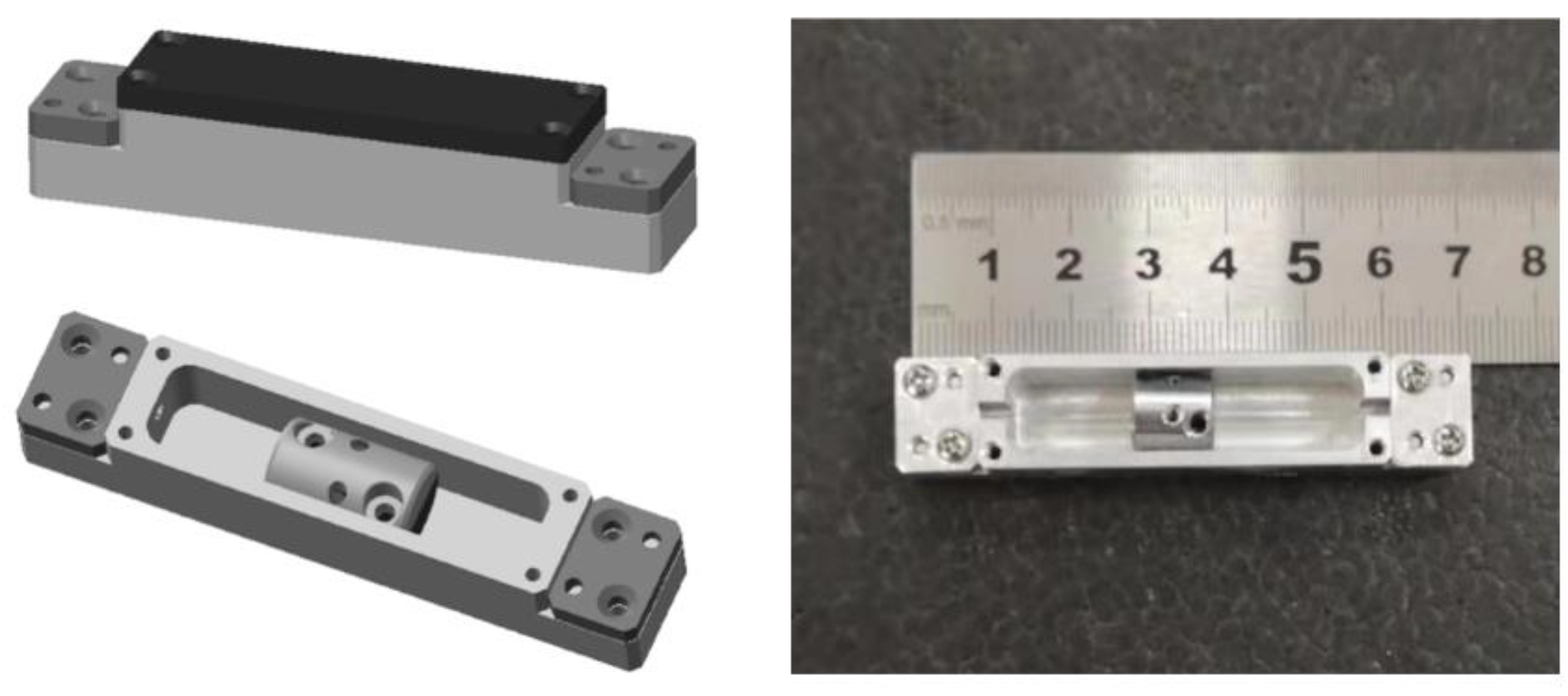
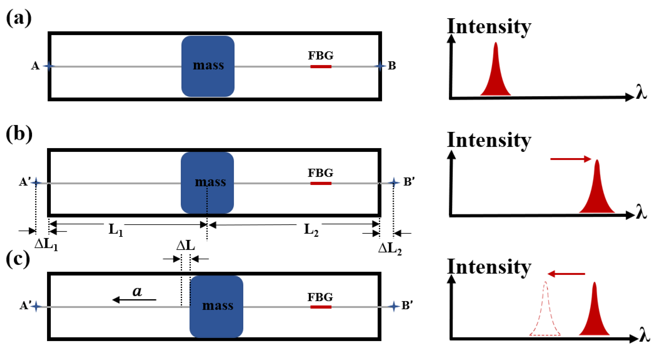
2. Sensing Principle and Design of FBG-Based Accelerometer

The structure diagram of the accelerometer is shown in Figure 1. The FBG was fixed with a mass block oscillator in the aluminum cavity, in which the mass block was a symmetrical cylinder which could freely oscillate inside the cavity and generate various stains along the FBG. By controlling the location of the mass block oscillator to change the length of the force arm on the FBG, the detection sensitivity can be tuned. Figure 2 shows the force analysis diagram of the proposed accelerometer, in which the grating is stretched repeatedly by the mass block as the structure is applied for axial vibration, leading to the shift in the central wavelength of the FBG. The fiber was fixed from A to B in the cavity, which be elongated from A’ to B’ after pre-stretching.
The corresponding theoretical derivation is presented as follows for the above-mentioned accelerometer. When the accelerometer is static, through the axial force on the mass, we can obtain the following formula:
L 1 L 1 = L 2 L 2
where L 1 and L 2 are the lengths of the fiber on both sides of the mass block in the groove, and the sum of L 1   and L 2 is the length of the cavity C ; L 1 and L 2 are the corresponding deformations after the fiber is pre-stretched. When the mass is subjected to axial acceleration a , the force applied on the mass can be expressed as
L 1 L L 1 E · S + L 2 + L L 2 E · S = m a
where L is the deformation change of the fiber on both sides of the mass caused by acceleration a , and the weight of the mass block is m ; E is the composite Young’s modulus, and S is the cross-sectional area of the fiber. The fiber in the groove should be pre-stretched before being fixed, in which the wavelengths of the FBG before and after pre-stretching are shown in Figure 2a,b. The wavelength shift caused by acceleration a can be expressed as
λ = ( 1 p e ) L L 2 λ
where p e is the elastic-optical coefficient of the grating, and λ is the wavelength of the FBG after pre-stretching. Define a nondimensional parameter P = L 1 C as the regulatory factor of the accelerometer, which is determined by L 1 and the length of the cavity C .
The sensitivity of the accelerometer can be expressed as
S = λ a = m λ ( 1 p e ) E · S · P
As shown in Figure 2c, when the accelerometer is under the condition of acceleration a , the center wavelength of the grating will shift in the same direction. In the accelerometer structure, the FBG could be equivalent to springs, meaning the elastic coefficient of the system can be expressed as
k = ( 1 L 1 + 1 L 2 ) E · S
The resonant frequency of the accelerometer can be obtained:
f = 1 2 π k m = 1 2 π ( 1 C ( P P 2 ) ) E · S m
where k is the equivalent elastic coefficient of the system. The sensitivity and resonance frequency of the accelerometer are related not only to m but also to L 1 and L 2 . The above equations further show that the accelerometer sensitivity is linearly proportional to parameter P, and the resonant frequency is quadratically proportional to parameter P, which reaches a minimum when P is 0.5.

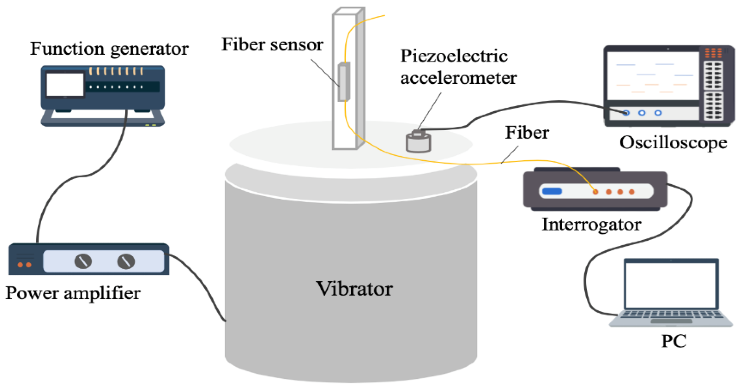
3. Characterization of the Accelerometer

According to the above theoretical derivation, it is obvious that the sensitivity of the accelerometer is related to the position and weight of the mass. In order to verify the influence of the mass position on accelerometer performance, six accelerometers with different P parameters were constructed by changing the position of the mass, and the P parameters of the six accelerometers are 0.125, 0.25, 0.375, 0.5, 0.625 and 0.75.
A test system was established to measure the time and linearity response of the accelerometers, as shown in Figure 3. The proposed accelerometer was installed on the vibrator (MB Dynamic PM25) for testing, and a commercial standard piezoelectric accelerometer (Dytran 3255A3) was also fixed on the vibrator as a reference. The output signal of the function generator is sent to the vibrator after amplifying by the power amplifier. The amplitude and frequency of the vibrator can be changed by adjusting the amplitude and frequency of the function generator, and the parameter values of the standard piezoelectric accelerometer for reference are displayed on the oscilloscope (Tektronix MSO54) in real time. An FBG interrogation system based on FBGA-F1525 purchased from Bayspec, which has a 1 pm wavelength resolution and an up to 8 kHz acquisition frequency, was used to monitor the wavelength shift of the proposed accelerometer.
The time response capability of accelerometers 1–6 with different P parameters subjected to a sinusoidal excitation signal at the vibration frequency of 100 Hz and vibration acceleration of 0.5 g (g = 10 m/s2) is shown in Figure 4. These response waveforms demonstrate the accelerometer has an excellent vibration measurement capability. Additionally, it can be clearly seen that the wavelength shift is increased as parameter P is increased, which indicates that the responsivity of the accelerometer is related to the position of the mass.
To verify the above numerical analysis, we experimentally tested the sensitivity and resonance frequency of six accelerometers with different P parameters (0.125, 0.25, 0.375, 0.5, 0.625, 0.75). The experiment results are listed in Table 1. During the experiment, the six accelerometers were subjected to a sinusoidal excitation signal with vibration acceleration from 0.1 to 1 g under a 100 Hz vibration frequency. Figure 5a shows that the wavelength shift of the FBG was linearly proportional to the vibration acceleration amplitude, and different P parameters have a different vibration sensitivity, where the experimental results show that the vibration sensitivities of the six accelerometers were 7.6 pm/g, 15.8 pm/g, 19.3 pm/g, 25.4 pm/g, 30.6 pm/g and 35.7 pm/g, respectively. Furthermore, we also compared the relationship between the vibration sensitivity and parameter P, which is plotted in Figure 5b. As it shown in Figure 5b, the vibration sensitivity of the proposed accelerometers is linearly proportional to parameter P, in which the vibration sensitivity can be increased by 4.262 pm/g when there is a 0.1 increment in the value of P. The experiment results agree very well with the numerical analysis.
Furthermore, we experimentally tested the frequency response curve. In the experiment, we kept the vibration acceleration amplitude at 0.5 g and adjusted the frequency from 0 to 1000 Hz with a 20 Hz interval. The experiment results are shown in Figure 6a, in which the resonance frequencies of accelerometers 1–6 are 820 Hz, 500 Hz, 460 Hz, 440 Hz, 460 Hz and 500 Hz, respectively. The relationship between the resonant frequency and parameter P shows a quadratic shape, in which, as there is an increase in parameter P , the resonant frequency decreases gradually from 820 to 440 Hz and then increases to 500 Hz (see Figure 6b). The experiment results match very well with the numerical analysis.
Transverse anti-interference ability is a very important characteristic for one-dimensional accelerometers in practical application. We tested the transverse anti-interference feature of the proposed accelerometer. In the experiment, we employed accelerometer 4 to apply a vibration frequency of 100 Hz at the vibration acceleration values of 0.3 g, 0.6 g and 1 g along the transverse and axial directions. Responses in two directions are shown in Figure 7. The wavelength shifts of the oscillator-accelerometer applied the vibration along the transverse direction, both instances of which were 1 pm. This may be limited by our test equipment whose resolution is 1 pm, meaning that we cannot present an accurate value of orthogonal vibration isolation. Additionally, the results of the transverse direction can be considered as background noise. The experiment result indicates that the proposed accelerometer has good transverse anti-interference performance and can be well integrated for multi-dimensional vibration monitoring.

4. Conclusions

In this paper, we proposed an oscillator-accelerometer based on FBG, which exhibited a tunable sensitivity and resonance frequency. These properties of the oscillator-accelerometer are related to the location of the mass oscillator, which is characterized by the regulatory factor of the nondimensional parameter P. By controlling the regulatory factor P of the accelerometer, the sensitivity and the resonance frequency could be regulated. The P parameter is linearly proportional to the accelerometer sensitivity and quadratically proportional to the resonance frequency. In addition, we conducted a series of experiments with different P parameters of 0.125, 0.25, 0.375, 0.5, 0.625 and 0.75, which manifested a 7.6–35.7 pm/g sensitivity adjustment range and a 0 − 440 Hz flat frequency range. Specifically, the sensitivity and the resonance frequency of the accelerometer increase as parameter P increases, and it could achieve a maximum sensitivity of 35.7 pm/g and a maximum frequency of 440 Hz, which is in good agreement with the theoretical derivation. The proposed accelerometer also showed very strong transverse anti-interference, meaning that it can be integrated for multi-dimension acceleration detection, which could potentially be applied to vibration monitoring of industrial equipment and civil engineering.

Author Contributions

Conceptualization, Z.Y. and J.Y.; methodology, J.T. and Z.Y.; software, Q.S.; validation, X.X., J.T. and Q.S.; formal analysis, X.X.; investigation, X.X. and Z.Y.; resources, Z.Y. and J.Y.; data curation, X.X. and J.T.; writing—original draft preparation, X.X.; writing—review and editing, Z.Y. and Y.S.; visualization, X.X.; supervision, Z.Y.; project administration, J.Y. All authors have read and agreed to the published version of the manuscript.

Funding

This research received no external funding.

Institutional Review Board Statement

This research did not involve humans or animals.

Informed Consent Statement

This research did not involve humans.

Data Availability Statement

This research did not report any data.

Acknowledgments

This work was supported, in part, by Major Projects of Technical Innovation of Hubei 2019AAA053.

Conflicts of Interest

The authors declare no conflict of interest.

References

  1. Stolarik, M.; Nedoma, J.; Martinek, R.; Kepak, S.; Hrubesova, E.; Pinka, M.; Kolarik, J. New Methods to Seismic Monitoring: Laboratory Comparative Study of Michelson Fiber-Optic Interferometer and Pneumatic Measurement Systems. Photonics 2021, 8, 147. [Google Scholar] [CrossRef]
  2. Zhang, W.; Wang, Z.; Huang, W.; Liu, W.; Li, L.; Li, F. Fiber laser sensors for micro seismic monitoring. Measurement 2016, 79, 203–210. [Google Scholar] [CrossRef]
  3. Yuan, L.; Liu, Z.; Yang, J.; Guo, C. Fiber Optic Brownian Motion Force Sensor. In Proceedings of the 12th International Conference on Optical Fiber Sensors, Cancun, Mexico, 23–27 October 2006. [Google Scholar] [CrossRef]
  4. Wu, X.; Zhang, F.; Zhang, X.; Li, S. Performance comparison of fiber laser geophones and moving-coil geophones. In Proceedings of the International Symposium on Optoelectronic Technology and Application 2014, Beijing, China, 13–15 May 2014; Volume 9297. [Google Scholar]
  5. Lu, Y.; Li, Z.; Liao, W.I. Damage monitoring of reinforced concrete frames under seismic loading using cement-based piezoelectric sensor. Mater. Struct. 2011, 44, 1273–1285. [Google Scholar] [CrossRef]
  6. Jackson, D.A.; Ribeiro, A.L.; Reekie, L.; Archambault, J.L. Simple multiplexing scheme for a fiber-optic grating sensor network. Opt. Lett. 1993, 18, 1192–1194. [Google Scholar] [CrossRef] [PubMed]
  7. Berkoff, T.; Kersey, A. Experimental demonstration of a fiber Bragg grating accelerometer. IEEE Photonics Technol. Lett. 1996, 8, 1677–1679. [Google Scholar] [CrossRef]
  8. Spero, R.E.; Whitcomb, S.E. The Laser Interferometer Gravitational-wave Observatory (LIGO). Opt. Photonics News 1995, 6, 35–39. [Google Scholar] [CrossRef]
  9. Gutiérrez, N.; Galvin, P.; Lasagni, F. Low weight additive manufacturing FBG accelerometer: Design, characterization and testing. Measurement 2018, 117, 295–303. [Google Scholar] [CrossRef]
  10. Peng, P.; Yang, J.; Gao, F. High-sensitivity fiber optic accelerometer based on multilayer fiber coils. In Proceedings of the 23rd International Conference on Optical Fibre Sensors, Santander, Spain, 2–6 June 2014. [Google Scholar]
  11. Yu, H.; Luo, Z.; Zheng, Y.; Ma, J.; Li, Z.; Jiang, X.; Li, Z. Temperature-Insensitive Vibration Sensor with Kagomé Hollow-Core Fiber Based Fabry–Perot Interferometer. J. Light. Technol. 2019, 37, 2261–2269. [Google Scholar] [CrossRef]
  12. Liu, T.; Cheng, J.; Lv, D.; Luo, Y.; Yan, Z.; Wang, K.; Liu, C.; Liu, D.; Sun, Q. DBR Fiber Laser Based High-Resolution Accelerometer Network. J. Light. Technol. 2019, 37, 2946–2953. [Google Scholar] [CrossRef]
  13. Guo, Y.; Zhang, D.; Fu, J.; Liu, S.; Zhu, F. Development and operation of a fiber Bragg grating based online monitoring strategy for slope deformation. Sens. Rev. 2015, 35, 348–356. [Google Scholar] [CrossRef]
  14. Todd, M.D.; Johnson, G.A.; Althouse, B.A.; Vohra, S.T. Flexural beam-based fiber Bragg grating accelerometers. IEEE Photonics Technol. Lett. 1998, 10, 1605–1607. [Google Scholar] [CrossRef]
  15. Du, J.; Li, L.; Fan, X.; Liu, Q.; He, Z. Sensitivity Enhancement for Fiber Bragg Grating Sensors by Four Wave Mixing. Photonics 2015, 2, 426–439. [Google Scholar] [CrossRef] [Green Version]
  16. Chen, X.; Wang, E.; Jiang, Y.; Zhan, H.; Li, H.; Lyu, G.; Sun, S. Generalized Resonance Sensor Based on Fiber Bragg Grating. Photonics 2021, 8, 156. [Google Scholar] [CrossRef]
  17. Feng, D.; Qiao, X.; Yang, H.; Rong, Q.; Wang, R.; Du, Y.; Hu, M.; Feng, Z. A Fiber Bragg Grating Accelerometer Based on a Hybridization of Cantilever Beam. IEEE Sens. J. 2014, 15, 1532–1537. [Google Scholar] [CrossRef]
  18. Mita, A.; Yokoi, I. Fiber bragg grating accelerometer for structural health monitoring. In Proceedings of the Fifth International Conference on Motion and Vibration Control (MOVIC 2000), Sydney, Australia, 4–8 December 2000. [Google Scholar]
  19. Wang, J.; Wei, L.; Li, R.; Liu, Q.; Yu, L.; Li, T.; Tan, Y. An FBG-Based 2-D Vibration Sensor with Adjustable Sensitivity. IEEE Sens. J. 2017, 17, 4716–4724. [Google Scholar] [CrossRef]
  20. Li, T.; Tan, Y.; Han, X.; Zheng, K.; Zhou, Z. Diaphragm Based Fiber Bragg Grating Acceleration Sensor with Temperature Compensation. Sensors 2017, 17, 218. [Google Scholar] [CrossRef] [PubMed] [Green Version]
  21. Guo, T.; Zhang, T.; Li, Y.; Qiao, X. Highly Sensitive FBG Seismometer With a 3D-Printed Hexagonal Configuration. J. Light. Technol. 2020, 38, 4588–4595. [Google Scholar] [CrossRef]
  22. Zhang, Y.; Qiao, X.; Liu, Q.; Yu, D.; Gao, H.; Shao, M.; Wang, X. Study on a fiber Bragg grating accelerometer based on com-pliant cylinder. Opt. Fiber Technol. 2015, 26, 229–233. [Google Scholar] [CrossRef]
  23. Zhu, J.; Wang, J.; Gan, P.; Hu, Z.; Hu, Y. Design and Analysis of a Novel Dual FBG Accelerometer Based on Lantern Shape Metallic Shells. IEEE Sens. J. 2017, 17, 5130–5135. [Google Scholar] [CrossRef]
  24. Wang, X.; Guo, Y.; Xiong, L.; Wu, H. High-Frequency Optical Fiber Bragg Grating Accelerometer. IEEE Sens. J. 2018, 18, 4954–4960. [Google Scholar] [CrossRef]
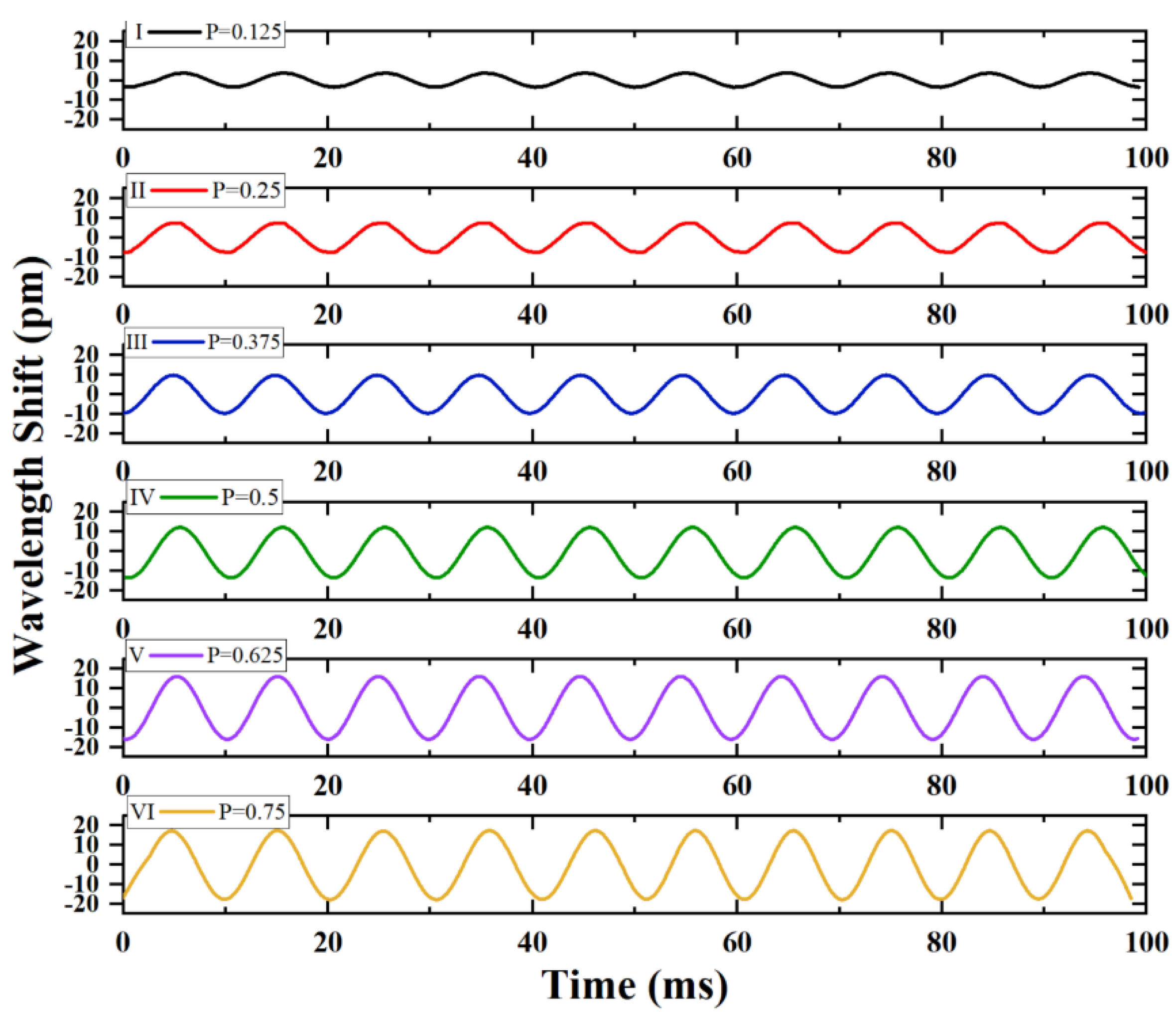
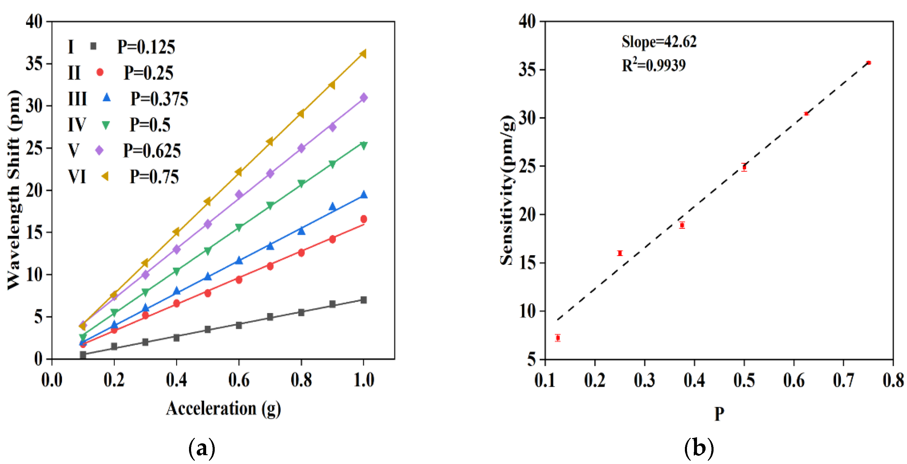
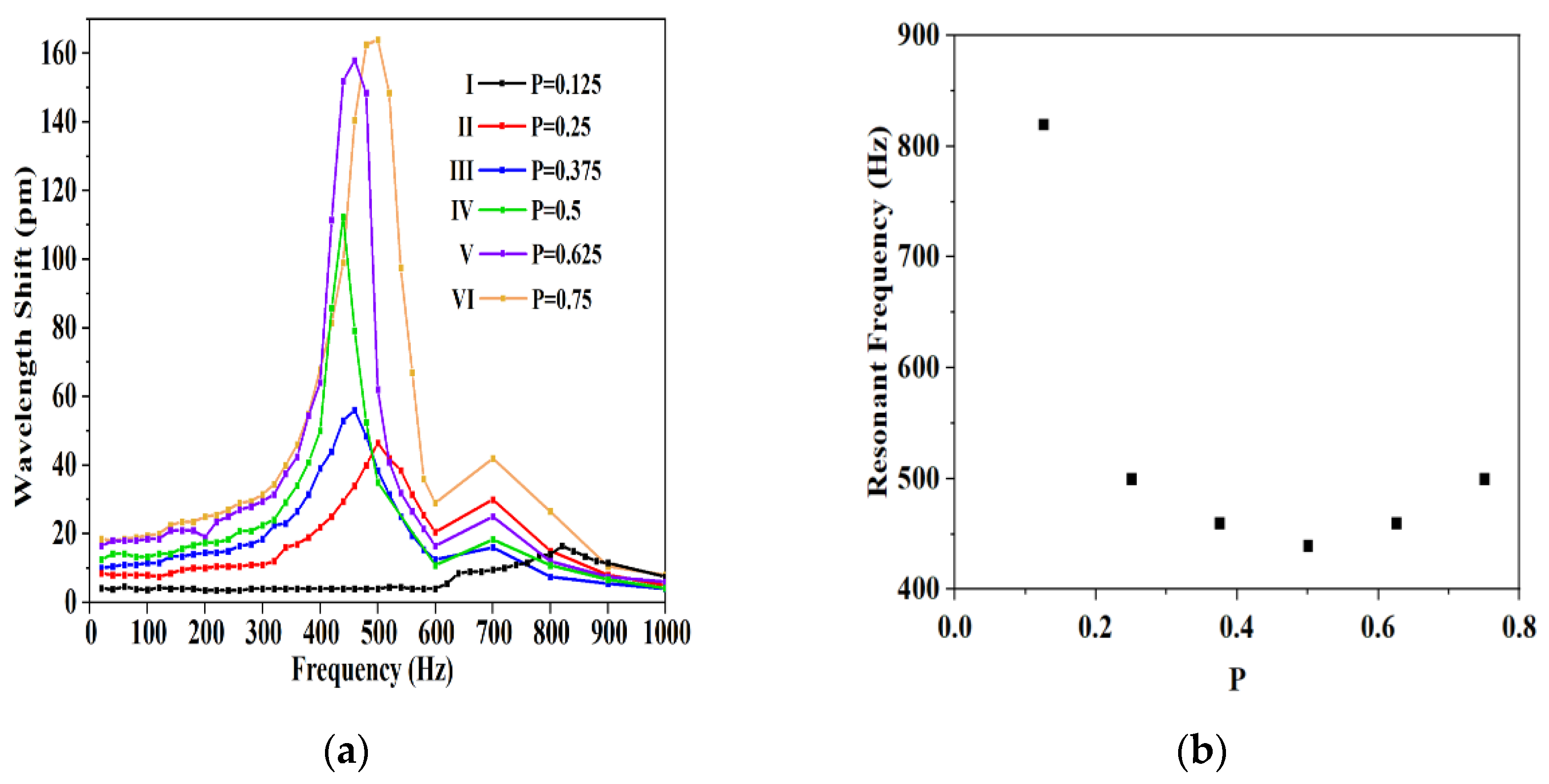
Figure 1. The structure diagram of the accelerometer.
Photonics 08 00223 g001
Figure 2. Schematic illustration of the principle. (a) Before pre-stretching; (b) wavelength drift magnification; (c) under axial acceleration a.
Photonics 08 00223 g002
Figure 3. The test system for FBG-based accelerometer.
Photonics 08 00223 g003
Figure 4. Time response capability of accelerometers 1–6 under a sinusoidal excitation signal with a vibration frequency of 100 Hz and vibration acceleration of 0.5 g.
Photonics 08 00223 g004
Figure 5. (a) Linear response capability of accelerometers 1–6 under a sinusoidal excitation signal with a vibration frequency of 100 Hz and vibration acceleration from 0.1 to 1 g. (b) The relationship between sensitivity and P.
Photonics 08 00223 g005
Figure 6. (a) Amplitude–frequency characteristic curves of accelerometers 1–6. (b) The relationship between resonance frequency and P .
Photonics 08 00223 g006
Figure 7. Comparison of axial and transverse responses of accelerometer 4 under a sinusoidal excitation signal with a vibration frequency of 100 Hz. (a) The vibration acceleration is 0.3 g. (b) The vibration acceleration is 0.6 g. (c) The vibration acceleration is 1 g.
Photonics 08 00223 g007
Table 1. Performance of the six accelerometers.
ParameterIIIIIIIVVVI
P0.1250.250.3750.50.6250.75
Sensitivity (pm/g)7.615.819.325.430.635.7
Frequency (Hz)820500460440460500
Publisher’s Note: MDPI stays neutral with regard to jurisdictional claims in published maps and institutional affiliations.

