Generation of Multiple Vector Optical Bottle Beams

 ,
, 
Abstract
:
1. Introduction
2. Methods
2.1. Theoretical Analysis
2.2. Experimental Setup
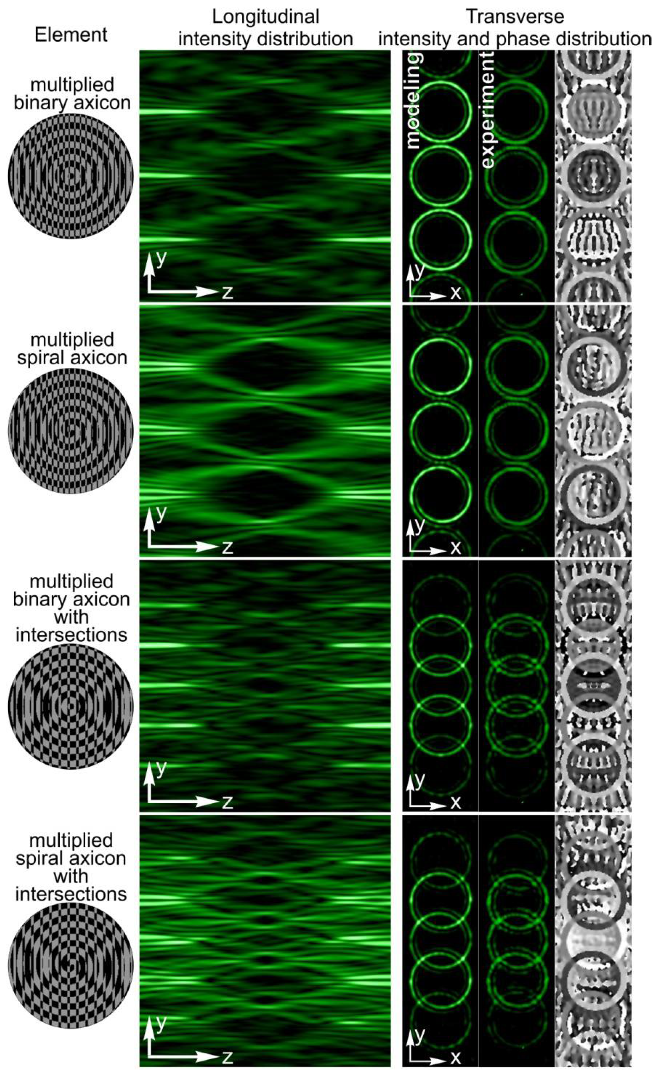
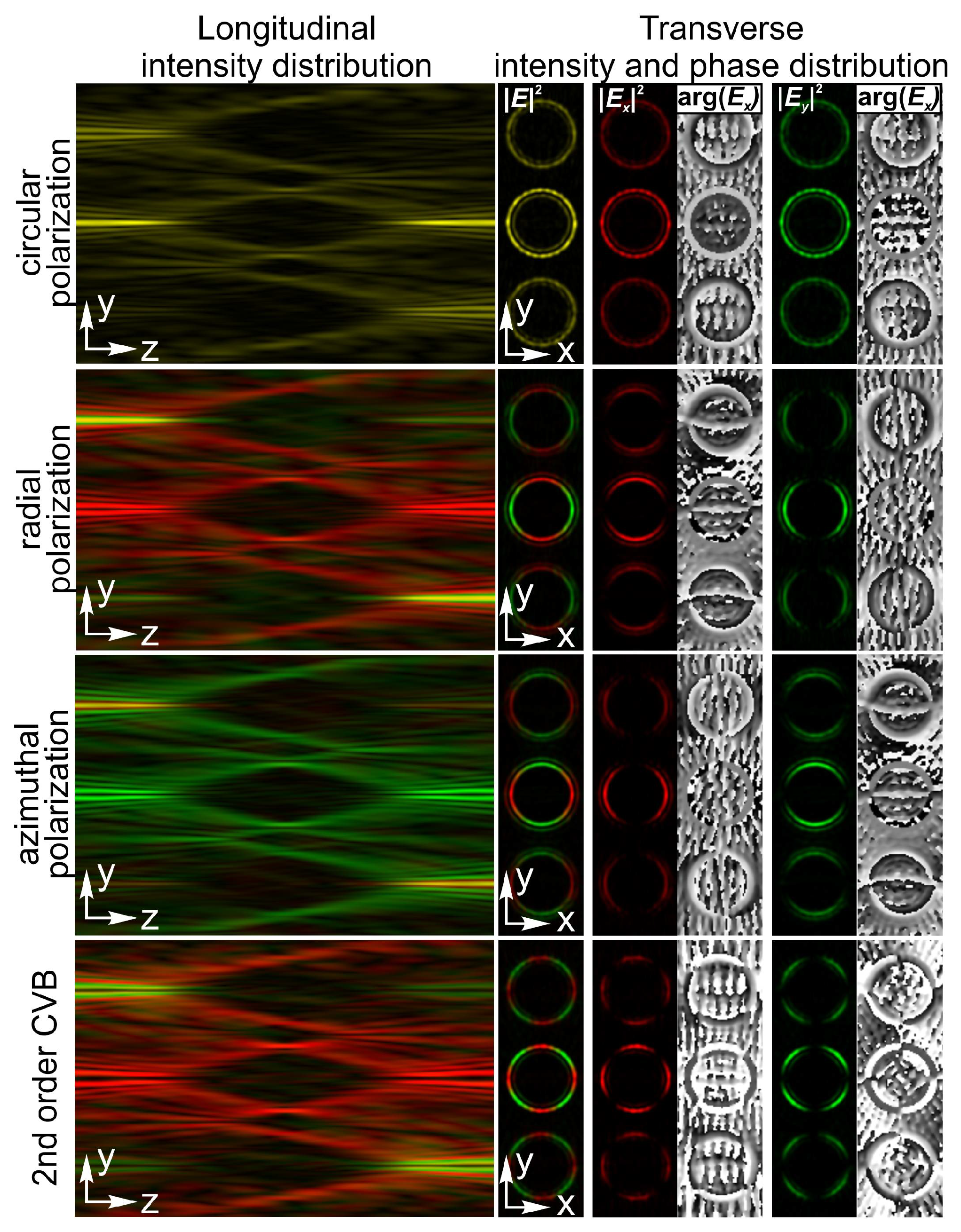
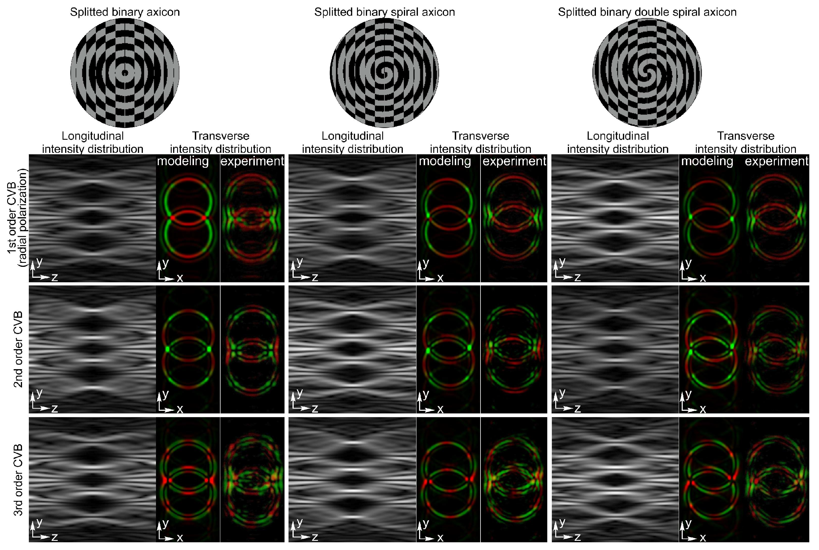
3. Results
4. Discussion
5. Conclusions
Author Contributions
Funding
Institutional Review Board Statement
Informed Consent Statement
Data Availability Statement
Acknowledgments
Conflicts of Interest
References
- Zhan, Q. Cylindrical vector beams: From mathematical concepts to applications. Adv. Opt. Photonics 2009, 1, 1–57. [Google Scholar] [CrossRef]
- Yao, B.; Yan, S.; Lei, M.; Peng, F.; Ma, B.; Ye, T. Optical trapping with cylindrical vector beams. In Proceedings of the 2011 Functional Optical Imaging, Ningbo, China, 3–4 December 2011. [Google Scholar]
- Moradi, H.; Shahabadi, V.; Madadi, E.; Karimi, E.; Hajizadeh, F. Efficient optical trapping with cylindrical vector beams. Opt. Express 2019, 27, 7266–7276. [Google Scholar] [CrossRef] [PubMed]
- Shvedov, V.; Davoyan, A.R.; Hnatovsky, C.; Engheta, N.; Krolikowski, W. A long-range polarization-controlled optical tractor beam. Nat. Photonics 2014, 8, 846–850. [Google Scholar] [CrossRef]
- Nivas, J.J.; Allahyari, E.; Cardano, F.; Rubano, A.; Fittipaldi, R.; Vecchione, A.; Paparo, D.; Marrucci, L.; Bruzzese, R.; Amoruso, S. Surface structures with unconventional patterns and shapes generated by femtosecond structured light fields. Sci. Rep. 2018, 8, 13613. [Google Scholar] [CrossRef] [PubMed]
- Nivas, J.J.; Allahyari, E.; Cardano, F.; Rubano, A.; Fittipaldi, R.; Vecchione, A.; Paparo, D.; Marrucci, L.; Bruzzese, R.; Amoruso, S. Vector vortex beams generated by q-plates as a versatile route to direct fs laser surface structuring. Appl. Surf. Sci. 2019, 471, 1028–1033. [Google Scholar] [CrossRef]
- Bomzon, Z.; Biener, G.; Kleiner, V.; Hasman, E. Radially and azimuthally polarized beams generated by space-variant dielectric subwavelength gratings. Opt. Lett. 2002, 27, 285–287. [Google Scholar] [CrossRef]
- He, Y.; Li, Y.; Liu, J.; Zhang, X.; Cai, Y.; Chen, Y.; Chen, S.; Fan, D. Switchable phase and polarization singular beams generation using dielectric metasurfaces. Sci. Rep. 2017, 7, 6814. [Google Scholar] [CrossRef]
- Yonezawa, K.; Kozawa, Y.; Sato, S. Generation of a radially polarized laser beam by use of the birefringence of a c-cut Nd:YVO4 crystal. Opt. Lett. 2006, 31, 2151–2153. [Google Scholar] [CrossRef]
- Cardano, F.; Marrucci, L. Spin-orbit photonics. Nat. Photonics 2015, 9, 776–778. [Google Scholar] [CrossRef]
- Beresna, M.; Gecevičius, M.; Kazansky, P.G.; Gertus, T. Radially polarized optical vortex converter created by femtosecond laser nanostructuring of glass. Appl. Phys. Lett. 2011, 98, 201101. [Google Scholar] [CrossRef]
- Maurer, C.; Jesacher, A.; Fürhapter, S.; Bernet, S.; Ritsch-Marte, M. Tailoring of arbitrary optical vector beams. New J. Phys. 2007, 9, 1–20. [Google Scholar] [CrossRef]
- Liu, S.; Qi, S.; Zhang, Y.; Li, P.; Wu, D.; Han, L.; Zhao, J. Highly efficient generation of arbitrary vector beams with tunable polarization, phase, and amplitude. Photonics Res. 2018, 6, 228–233. [Google Scholar] [CrossRef]
- Porfirev, A.; Khonina, S.; Azizian-Kalandaragh, Y.; Kirilenko, M. Efficient generation of arrays of closed-packed high-quality light rings. Photonics Nanostruct. Fundam. Appl. 2019, 37, 100736. [Google Scholar] [CrossRef]
- Han, L.; Liu, S.; Li, P.; Zhang, Y.; Cheng, H.; Gan, X.; Zhao, J. Managing focal fields of vector beams with multiple polarization singularities. Appl. Opt. 2016, 55, 9049–9053. [Google Scholar] [CrossRef]
- Ruffato, G.; Massari, M.; Romanato, F. Diffractive optics for combined spatial- and mode-division demultiplexing of optical vortices: Design, fabrication and optical characterization. Sci. Rep. 2016, 6, 24760. [Google Scholar] [CrossRef] [Green Version]
- Khonina, S.N.; Ustinov, A.V.; Fomchenkov, S.A.; Porfirev, A.P. Formation of hybrid higher-order cylindrical vector beams using binary multi-sector phase plates. Sci. Rep. 2018, 8, 14320. [Google Scholar] [CrossRef] [Green Version]
- Lu, T.H.; Huang, T.D.; Wang, J.G.; Wang, L.W.; Alfano, R.R. Generation of flower high-order Poincaré sphere laser beams from a spatial light modulator. Sci. Rep. 2016, 6, 39657. [Google Scholar] [CrossRef] [Green Version]
- Moreno, I.; Fernandez-Pousa, C.R.; Davis, J.; Franich, D.J. Polarization eigenvectors for reflective twisted nematic liquid crystal displays. Opt. Eng. 2001, 40, 2220–2226. [Google Scholar] [CrossRef]
- Khonina, S.N.; Volotovsky, S.G.; Ustinov, A.V.; Porfirev, A.P. Spatiotemporal dynamics of the polarisation state of laser radiation performed by lens-axicon combinations. Phys. Lett. A 2019, 383, 2535–2541. [Google Scholar] [CrossRef]
- Ni, J.; Wang, C.; Zhang, C.; Hu, Y.; Yang, L.; Lao, Z.; Xu, B.; Li, J.; Wu, D.; Chu, J. Three-dimensional chiral microstructures fabricated by structured optical vortices in isotropic material. Light Sci. Appl. 2017, 6, e17011. [Google Scholar] [CrossRef] [PubMed] [Green Version]
- Rodrigo, J.A.; Alieva, T. Freestyle 3D laser traps: Tools for studying light-driven particle dynamics and beyond. Optica 2015, 2, 812–815. [Google Scholar] [CrossRef]
- Alonso, B.; Lopez–Quintas, I.; Holgado, W.; Drevinskas, R.; Kazansky, P.G.; Hernández-García, C.; Sola, I.J. Complete spatiotemporal and polarization characterization of ultrafast vector beams. Commun. Phys. 2020, 3, 151. [Google Scholar] [CrossRef]
- Chowdhury, D.R.; Bhattacharya, K.; Chakroborty, A.K.; Ghosh, R. Possibility of an optical focal shift with polarization masks. Appl. Opt. 2003, 42, 3819–3826. [Google Scholar] [CrossRef]
- Iglesias, I.; Vohnsen, B. Polarization structuring for focal volume shaping in high-resolution microscopy. Opt. Commun. 2007, 271, 40–47. [Google Scholar] [CrossRef]
- Yang, Y.; Leng, M.; He, Y.; Liu, H.; Chang, Q.; Li, C. Focal shift in spatial-variant polarized vector Bessel–Gauss. beams. J. Opt. 2013, 15, 014003. [Google Scholar] [CrossRef]
- Khonina, S.N.; Ustinov, A.V.; Volotovsky, S.G. Shaping of spherical light intensity based on the interference of tightly focused beams with different polarizations. Opt. Laser Technol. 2014, 60, 99–106. [Google Scholar] [CrossRef]
- Khonina, S.N.; Porfirev, A.P. 3D transformations of light fields in the focal region implemented by diffractive axicons. Appl. Phys. B 2018, 124, 191. [Google Scholar] [CrossRef]
- Dyson, J. Circular and spiral diffraction gratings. Proc. R. Soc. Lond. A 1958, 248, 93–106. [Google Scholar] [CrossRef]
- Khonina, S.N.; Kotlyar, V.V.; Soifer, V.A.; Shinkaryev, M.V.; Uspleniev, G.V. Trochoson. Opt. Commun. 1992, 91, 158–162. [Google Scholar] [CrossRef]
- Rajesh, K.B.; Jaroszewicz, Z.; Anbarasan, P.M. Improvement of lens axicon’s performance for longitudinally polarized beam generation by adding a dedicated phase transmittance. Opt. Express 2010, 18, 26799–26805. [Google Scholar] [CrossRef]
- Shvedov, V.G.; Hnatovsky, C.; Shostka, N.; Krolikowski, W. Generation of vector bottle beams with a uniaxial crystal. J. Opt. Soc. Am. B 2012, 30, 1–6. [Google Scholar] [CrossRef]
- Richards, B.; Wolf, E. Electromagnetic diffraction in optical systems, II. Structure of the image field in an aplanatic system. Proc. R. Soc. Lond. A 1959, 253, 358–379. [Google Scholar] [CrossRef]
- Pereira, S.; Van De Nes, A. Superresolution by means of polarisation, phase and amplitude pupil masks. Opt. Commun. 2004, 234, 119–124. [Google Scholar] [CrossRef]
- Helseth, L. Optical vortices in focal regions. Opt. Commun. 2004, 229, 85–91. [Google Scholar] [CrossRef]
- Khonina, S.N.; Volotovsky, S.G. Controlling the contribution of the electric field components to the focus of a high-aperture lens using binary phase structures. J. Opt. Soc. Am. A 2010, 27, 2188–2197. [Google Scholar] [CrossRef] [PubMed]
- Khonina, S.N. Simple phase optical elements for narrowing of a focal spot in high-numerical-aperture conditions. Opt. Eng. 2013, 52, 091711. [Google Scholar] [CrossRef]
- Man, Z.; Bai, Z.; Zhang, S.; Li, J.; Li, X.; Ge, X.; Zhang, Y.; Fu, S. Focusing properties of arbitrary optical fields combining spiral phase and cylindrically symmetric state of polarization. J. Opt. Soc. Am. A 2018, 35, 1014–1020. [Google Scholar] [CrossRef]
- Khonina, S.N. Vortex beams with high-order cylindrical polarization: Features of focal distributions. Appl. Phys. A 2019, 125, 100. [Google Scholar] [CrossRef]
- McLeod, J.H. The Axicon: A New Type of Optical Element. J. Opt. Soc. Am. 1954, 44, 592. [Google Scholar] [CrossRef]
- Jaroszewicz, Z.; Burvall, A.; Friberg, A.T. Axicon—The most important optical element. Opt. Photonics News 2005, 16, 34–39. [Google Scholar] [CrossRef]
- Durnin, J. Exact solutions for nondiffracting beams I The scalar theory. J. Opt. Soc. Am. A 1987, 4, 651–654. [Google Scholar] [CrossRef]
- Turunen, J.; Vasara, A.; Friberg, A.T. Holographic generation of diffraction-free beams. Appl. Opt. 1988, 27, 3959–3962. [Google Scholar] [CrossRef] [PubMed]
- Khonina, S.N.; Kotlyar, V.V. Bessel-mode formers. Proc. SPIE 1995, 2363, 184–190. [Google Scholar] [CrossRef]
- Fedotowsky, A.; Lehovec, K. Far Field Diffraction Patterns of Circular Gratings. Appl. Opt. 1974, 13, 2638–2642. [Google Scholar] [CrossRef]
- Amidror, I. The Fourier-spectrum of circular sine and cosine gratings with arbitrary radial phases. Opt. Commun. 1998, 149, 127–134. [Google Scholar] [CrossRef] [Green Version]
- Shao, B.; Esener, S.C.; Nascimento, J.M.; Botvinick, E.L.; Berns, M.W. Dynamically adjustable annular laser trapping based on axicons. Appl. Opt. 2006, 45, 6421–6428. [Google Scholar] [CrossRef] [Green Version]
- Kotlyar, V.V.; Khonina, S.N.; Soifer, V. Calculation of phase formers of non-diffracting images and a set of concentric rings. Optik 1996, 102, 45–50. [Google Scholar]
- Kotlyar, V.V.; Kovalev, A.A.; Khonina, S.N.; Skidanov, R.V.; Soifer, V.A.; Elfstrom, H.; Tossavainen, N.; Turunen, J. Diffraction of conic and Gaussian beams by a spiral phase plate. Appl. Opt. 2006, 45, 2656–2665. [Google Scholar] [CrossRef]
- Ostrovsky, A.S.; Rickenstorff-Parrao, C.; Arrizón, V. Generation of the “perfect” optical vortex using a liquid-crystal spatial light modulator. Opt. Lett. 2013, 38, 534–536. [Google Scholar] [CrossRef]
- García-García, J.; Rickenstorff-Parrao, C.; Ramos-García, R.; Arrizón, V.; Ostrovsky, A.S. Simple technique for generating the perfect optical vortex. Opt. Lett. 2014, 39, 5305–5308. [Google Scholar] [CrossRef]
- Chen, M.; Mazilu, M.; Arita, Y.; Wright, E.; Dholakia, K. Dynamics of microparticles trapped in a perfect vortex beam. Opt. Lett. 2013, 38, 4919–4922. [Google Scholar] [CrossRef]
- Khonina, S.N.; Golub, I. Creating order with the help of randomness: Generating transversely random, longitudinally invariant vector optical fields. Opt. Lett. 2015, 40, 4070–4073. [Google Scholar] [CrossRef] [PubMed]
- Reddy, S.G.; Chithrabhanu, P.; Vaity, P.; Aadhi, A.; Prabhakar, S.; Singh, R.P. Non-diffracting speckles of a perfect vortex beam. J. Opt. 2016, 18, 055602. [Google Scholar] [CrossRef]
- Zhang, C.; Min, C.; Du, L.; Yuan, X.-C. Perfect optical vortex enhanced surface plasmon excitation for plasmonic structured illumination microscopy imaging. Appl. Phys. Lett. 2016, 108, 201601. [Google Scholar] [CrossRef]
- Manek, I.; Ovchinnikov, Y.B.; Grimm, R. Generation of a hollow laser beam for atom trapping using an axicon. Opt. Commun. 1998, 147, 67–70. [Google Scholar] [CrossRef]
- Khonina, S.N.; Kotlyar, V.V.; Skidanov, R.V.; Soifer, V.; Jefimovs, K.; Simonen, J.; Turunen, J. Rotation of microparticles with Bessel beams generated by diffractive elements. J. Mod. Opt. 2004, 51, 2167–2184. [Google Scholar] [CrossRef]
- Porfirev, A.P.; Skidanov, R.V. Generation of an array of optical bottle beams using a superposition of Bessel beams. Appl. Opt. 2013, 52, 6230–6238. [Google Scholar] [CrossRef]
- Khonina, S.N.; Ustinov, A.V. Binary multi-order diffraction optical elements with variable fill factor for the formation and detection of optical vortices of arbitrary order. Appl. Opt. 2019, 58, 8227–8236. [Google Scholar] [CrossRef]
- Khonina, S.N.; Ustinov, A.V.; Kirilenko, M.S.; Kuchmizhak, A.A.; Porfirev, A.P. Application of a binary curved fork grating for the generation and detection of optical vortices outside the focal plane. J. Opt. Soc. Am. B 2020, 37, 1714–1721. [Google Scholar] [CrossRef]
- Zhang, Y.; Guo, X.; Han, L.; Li, P.; Liu, S.; Cheng, H.; Zhao, J. Gouy phase induced polarization transition of focused vector vortex beams. Opt. Express. 2017, 25, 25725–25733. [Google Scholar] [CrossRef]
- Ustinov, A.V.; Porfir’ev, A.P.; Khonina, S.N. Effect of the fill factor of an annular diffraction grating on the energy distribution in the focal plane. J. Opt. Technol. 2017, 84, 580–587. [Google Scholar] [CrossRef]
- Alpmann, C.; Esseling, M.; Rose, P.; Denz, C. Holographic optical bottle beams. Appl. Phys. Lett. 2012, 100, 111101. [Google Scholar] [CrossRef]
- Hnatovsky, C.; Shvedov, V.G.; Krolikowski, W. The role of light-induced nanostructures in femtosecond laser micromachining with vector and scalar pulses. Opt. Express 2013, 21, 12651–12656. [Google Scholar] [CrossRef] [PubMed]
- Estevez, M.C.; Alvarez, M.; Lechuga, L.M. Integrated optical devices for lab-on-a-chip biosensing applications. Laser Photonics Rev. 2012, 6, 463–487. [Google Scholar] [CrossRef] [Green Version]
- Li, Y.; Xin, H.; Liu, X.; Zhang, Y.; Lei, H.; Li, B. Trapping and Detection of Nanoparticles and Cells Using a Parallel Photonic Nanojet Array. ACS Nano 2016, 10, 5800–5808. [Google Scholar] [CrossRef]


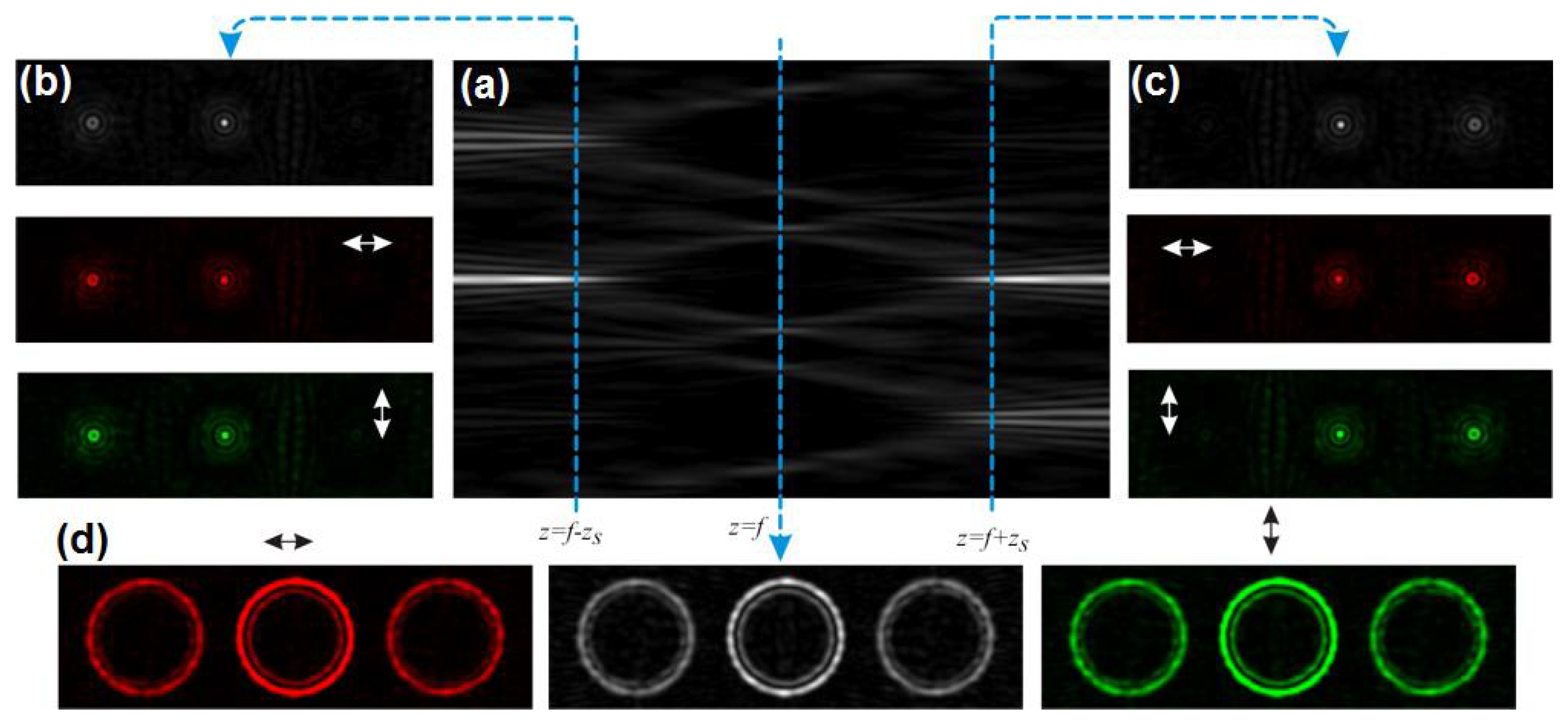
| Incident Vortex, l | Intensity Distributions before and after the Focal Plane | Detected Correlation Code |
|---|---|---|
| l = 0 |  | [0110] |
| l = 1 |  | [0001] |
| l = −1 |  | [1000] |
| l = 2 |  | [0000] |
| l = −2 |  | [0000] |
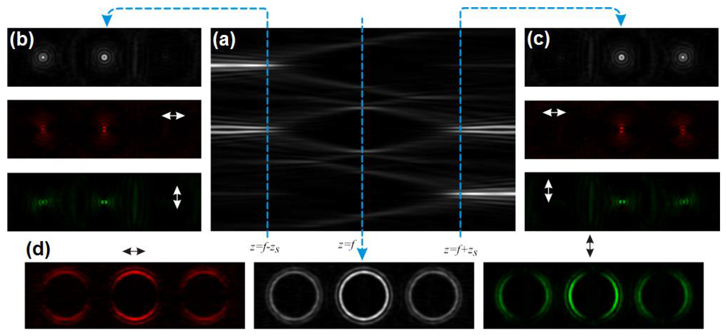
| Incident Vortex, l | Intensity Distributions before and after the Focal Plane | Detected Correlation Code |
|---|---|---|
| l = 0 |  | [1001] |
| l = 1 |  | [0110] |
| l = −1 |  | [0110] |
| l = 2 |  | [0001] |
| l = −2 |  | [1000] |
Publisher’s Note: MDPI stays neutral with regard to jurisdictional claims in published maps and institutional affiliations. |
© 2021 by the authors. Licensee MDPI, Basel, Switzerland. This article is an open access article distributed under the terms and conditions of the Creative Commons Attribution (CC BY) license (https://creativecommons.org/licenses/by/4.0/).
Share and Cite
Khonina, S.N.; Porfirev, A.P.; Volotovskiy, S.G.; Ustinov, A.V.; Fomchenkov, S.A.; Pavelyev, V.S.; Schröter, S.; Duparré, M. Generation of Multiple Vector Optical Bottle Beams. Photonics 2021, 8, 218. https://doi.org/10.3390/photonics8060218
Khonina SN, Porfirev AP, Volotovskiy SG, Ustinov AV, Fomchenkov SA, Pavelyev VS, Schröter S, Duparré M. Generation of Multiple Vector Optical Bottle Beams. Photonics. 2021; 8(6):218. https://doi.org/10.3390/photonics8060218
Chicago/Turabian StyleKhonina, Svetlana N., Alexey P. Porfirev, Sergey G. Volotovskiy, Andrey V. Ustinov, Sergey A. Fomchenkov, Vladimir S. Pavelyev, Siegmund Schröter, and Michael Duparré. 2021. "Generation of Multiple Vector Optical Bottle Beams" Photonics 8, no. 6: 218. https://doi.org/10.3390/photonics8060218