Crosstalk Reduction in Voxels for a See-Through Holographic Waveguide by Using Integral Imaging with Compensated Elemental Images

Abstract
:1. Introduction
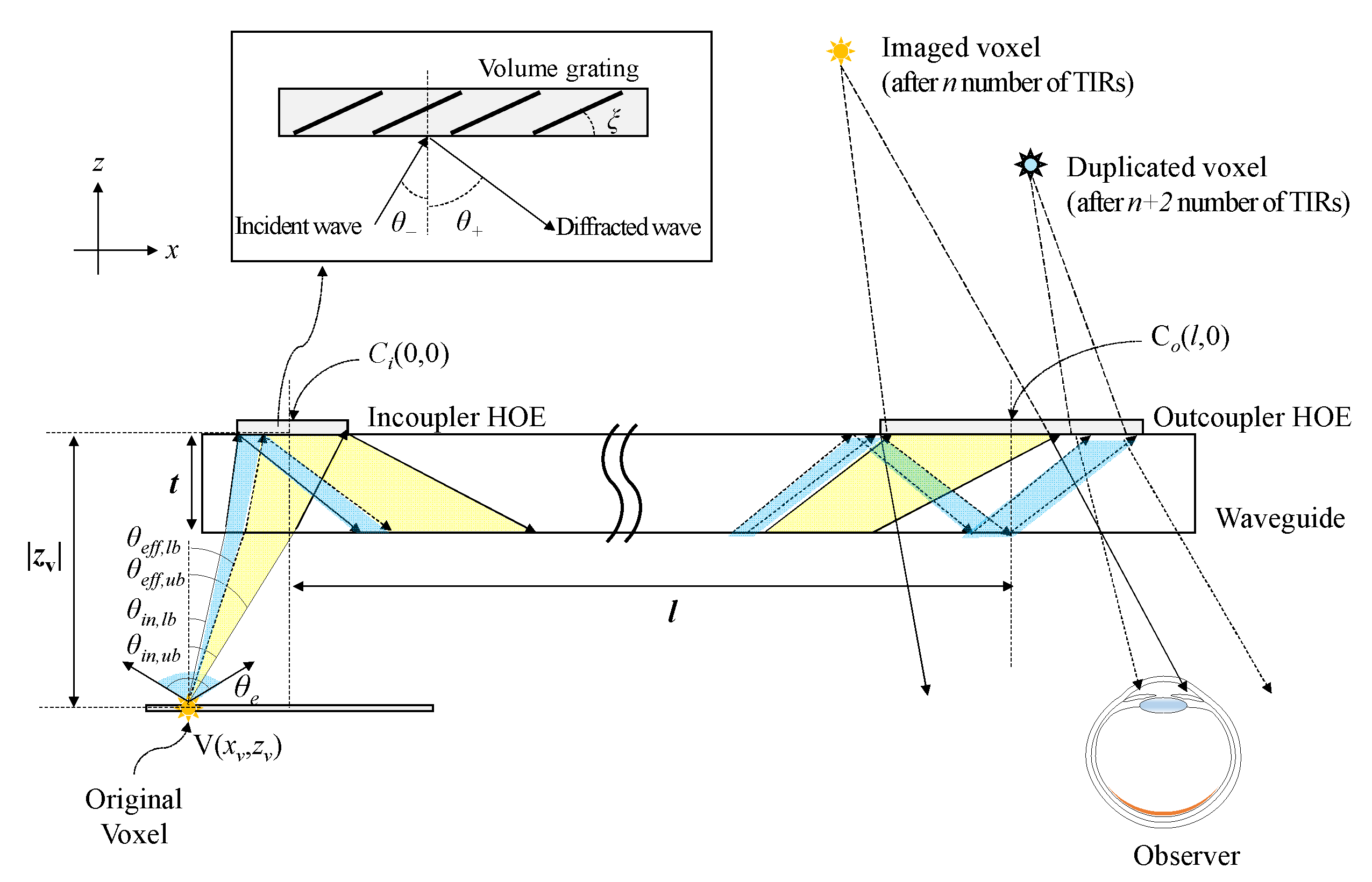
2. Principles
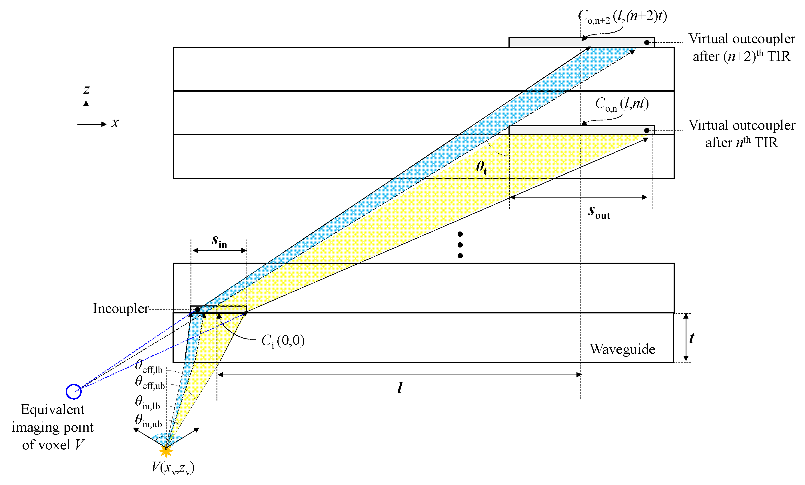
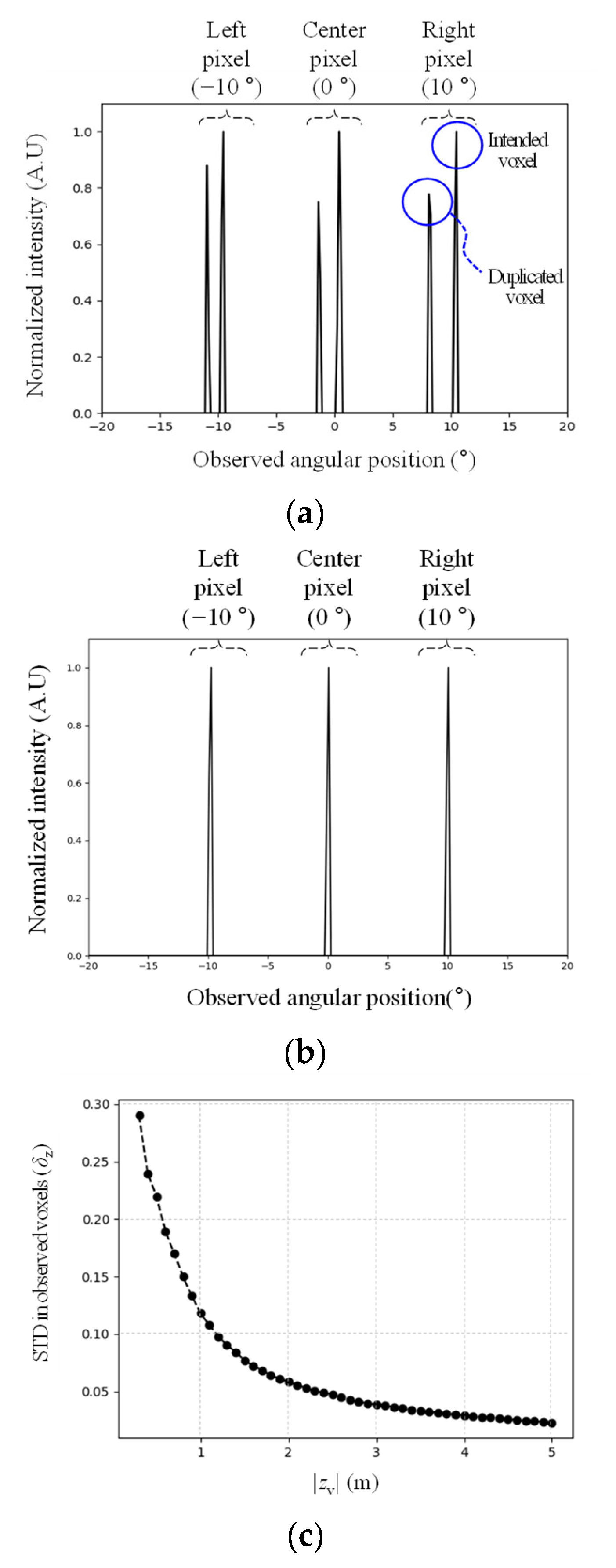
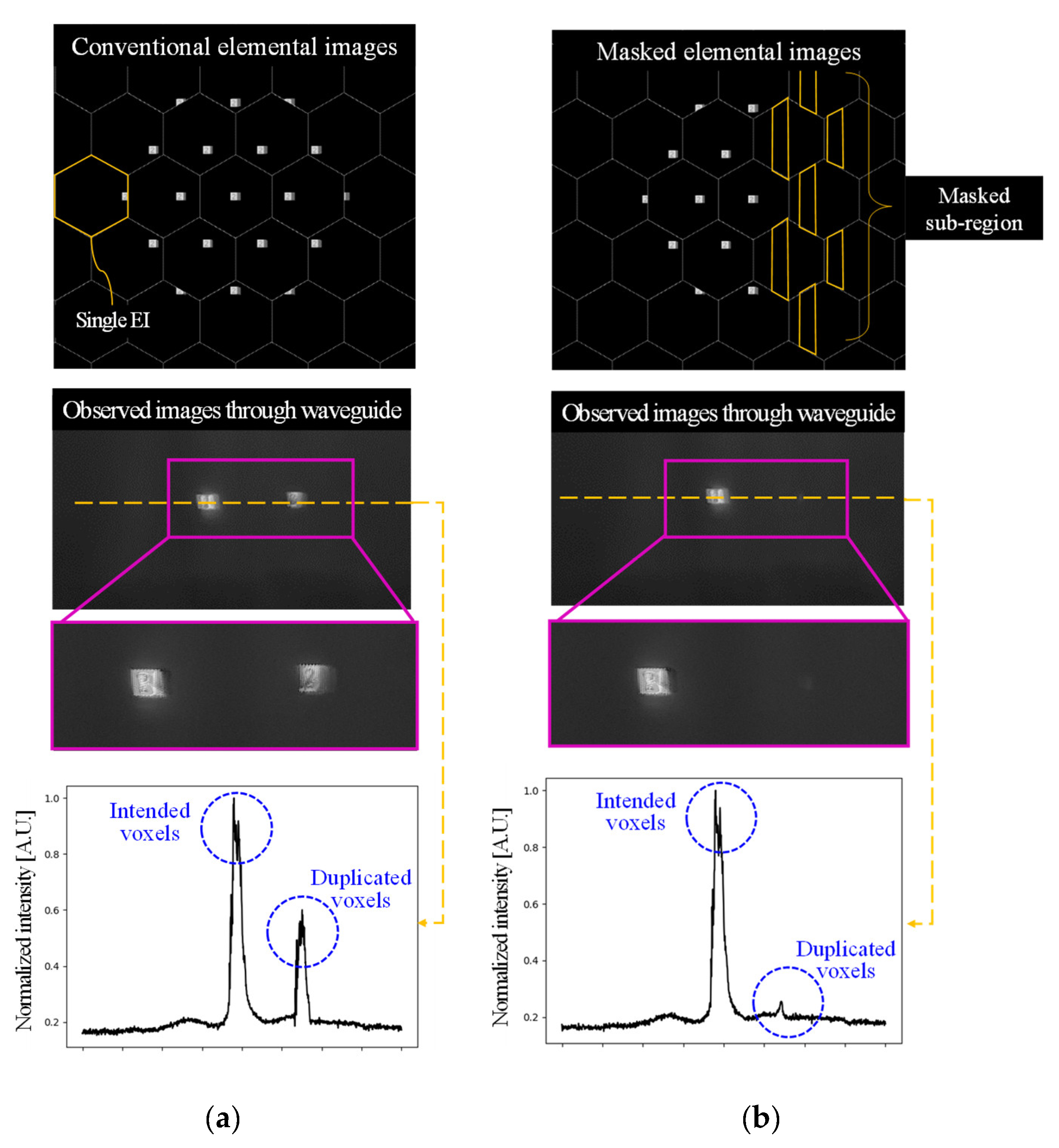
2.1. Voxel Duplication Problem in Holographic Waveguide
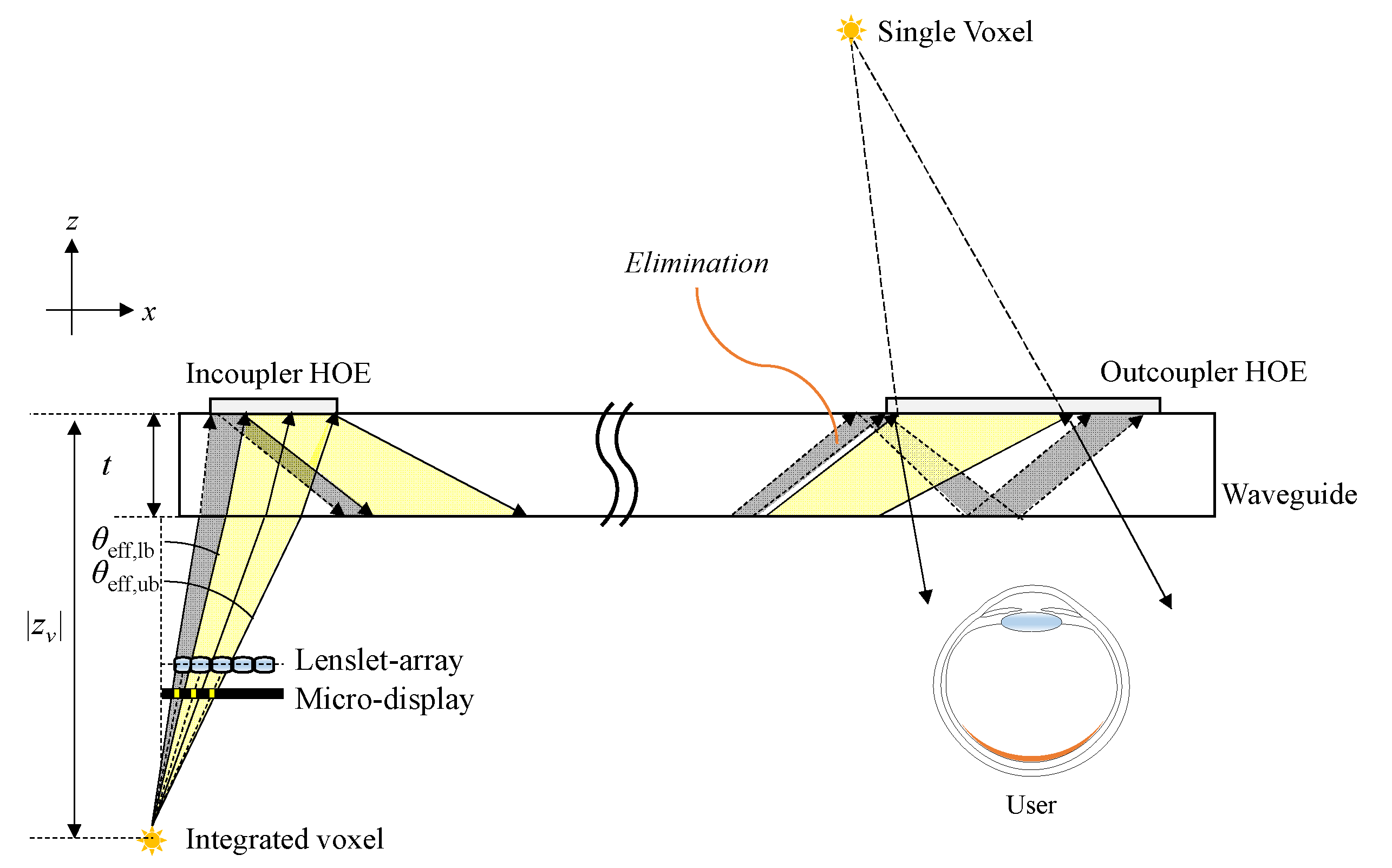
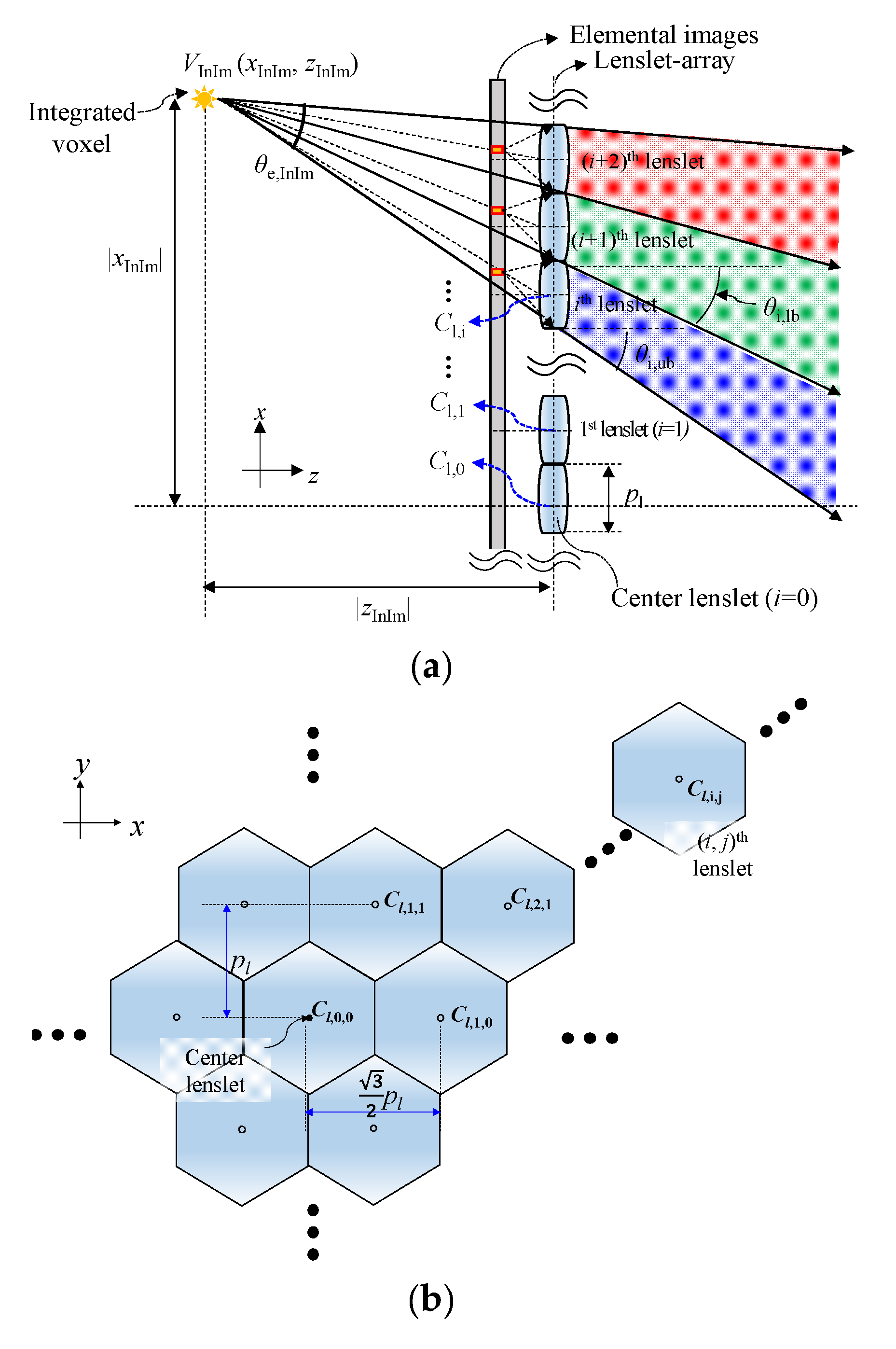
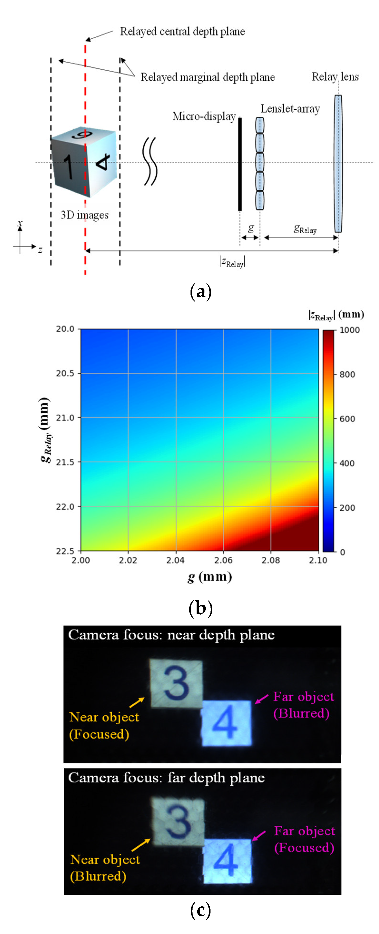
2.2. Emission Angle Adjustment for Voxels Using InIm
3. Results
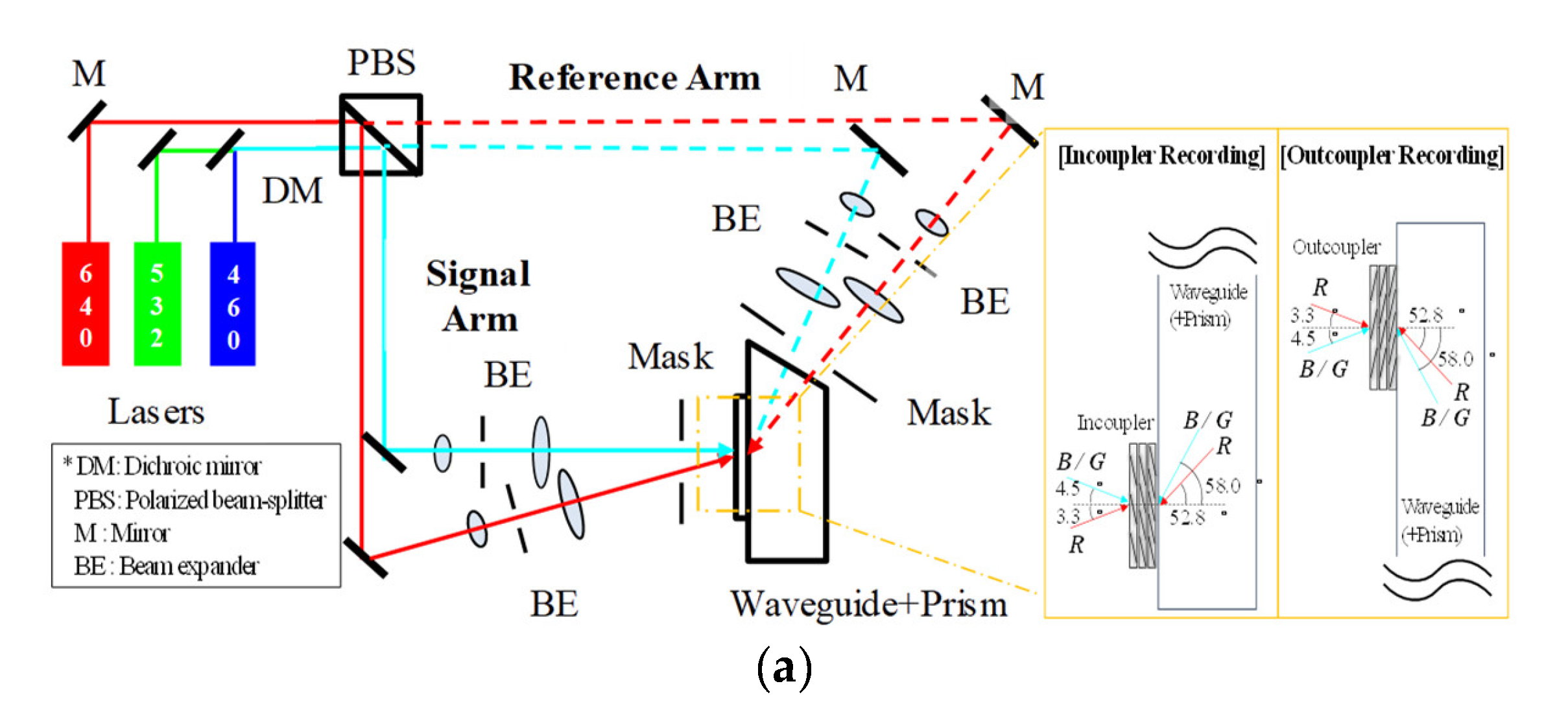
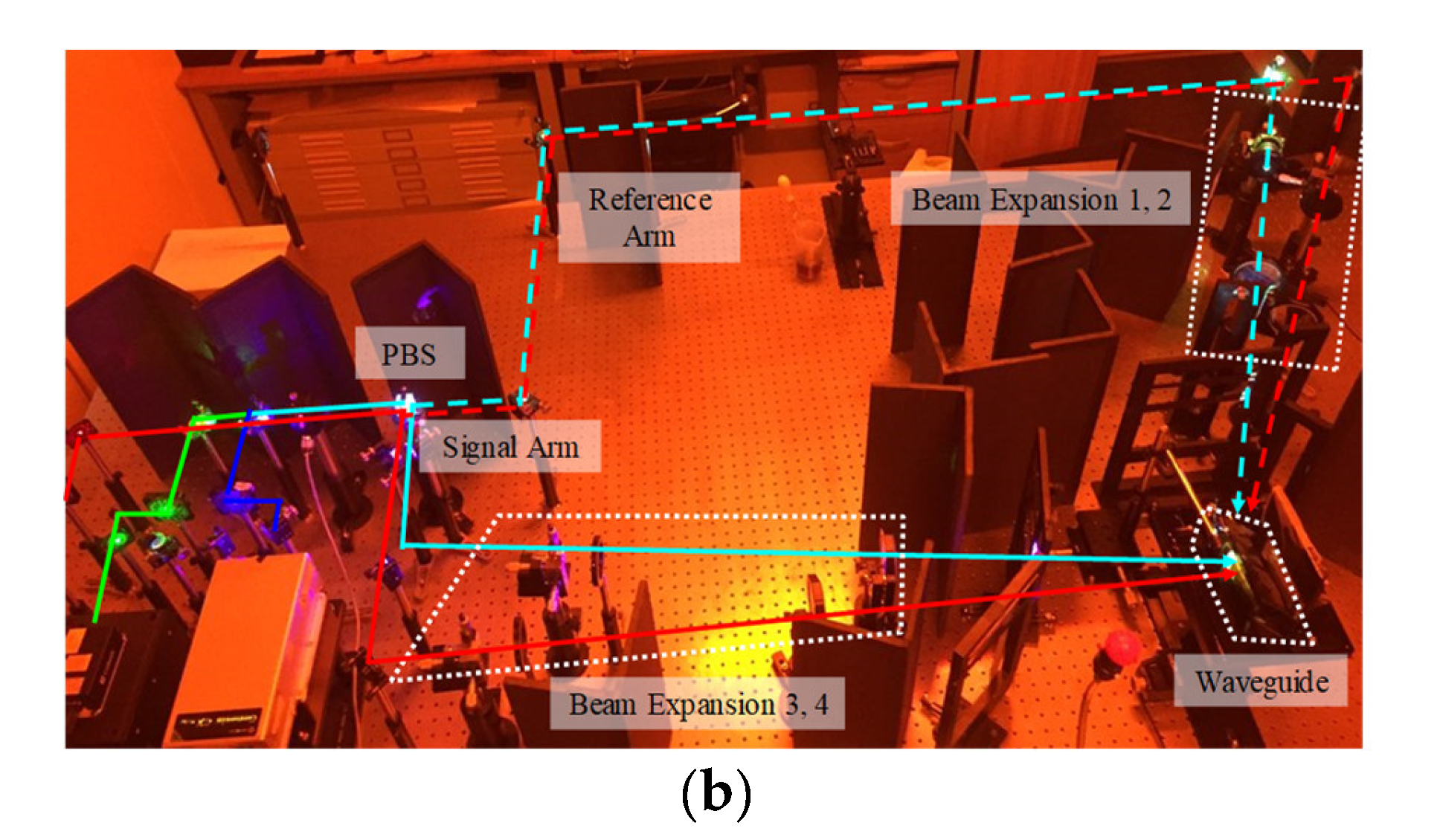
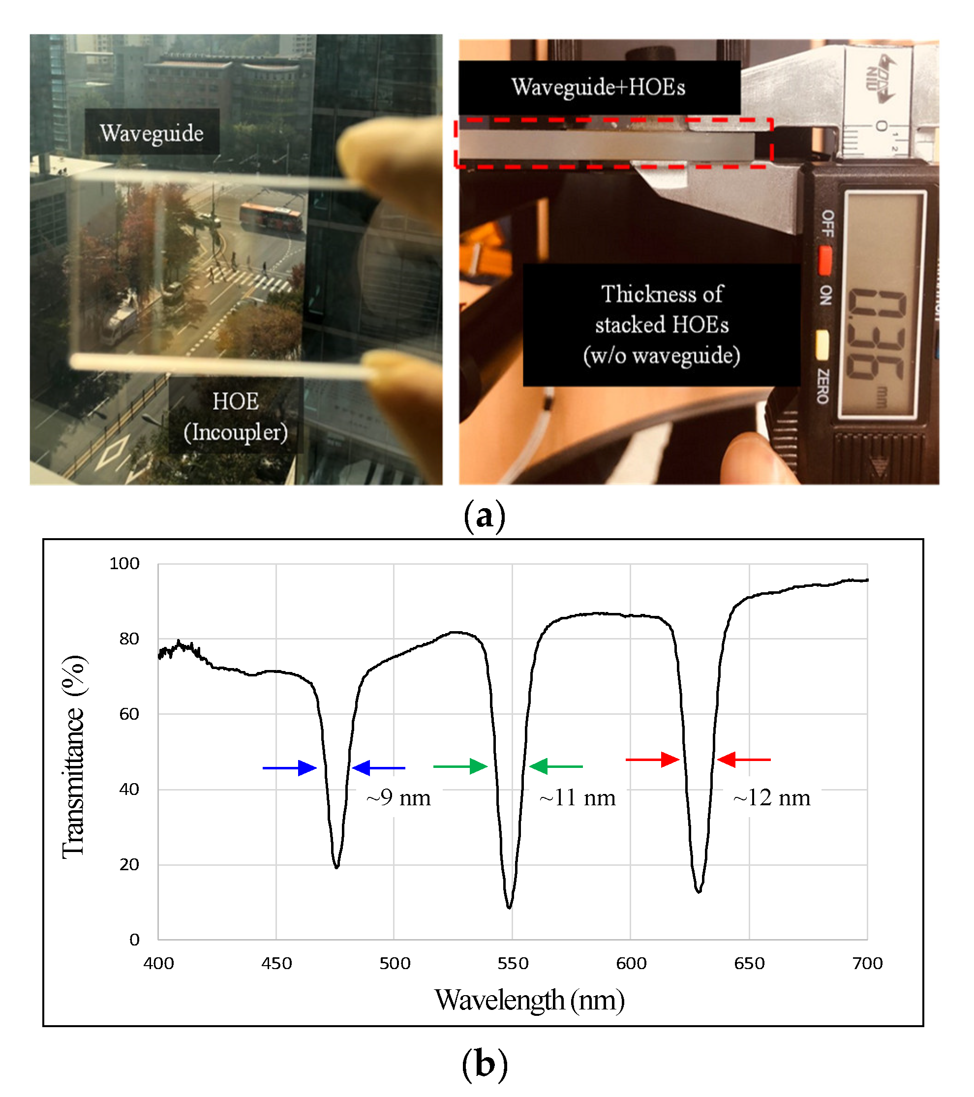
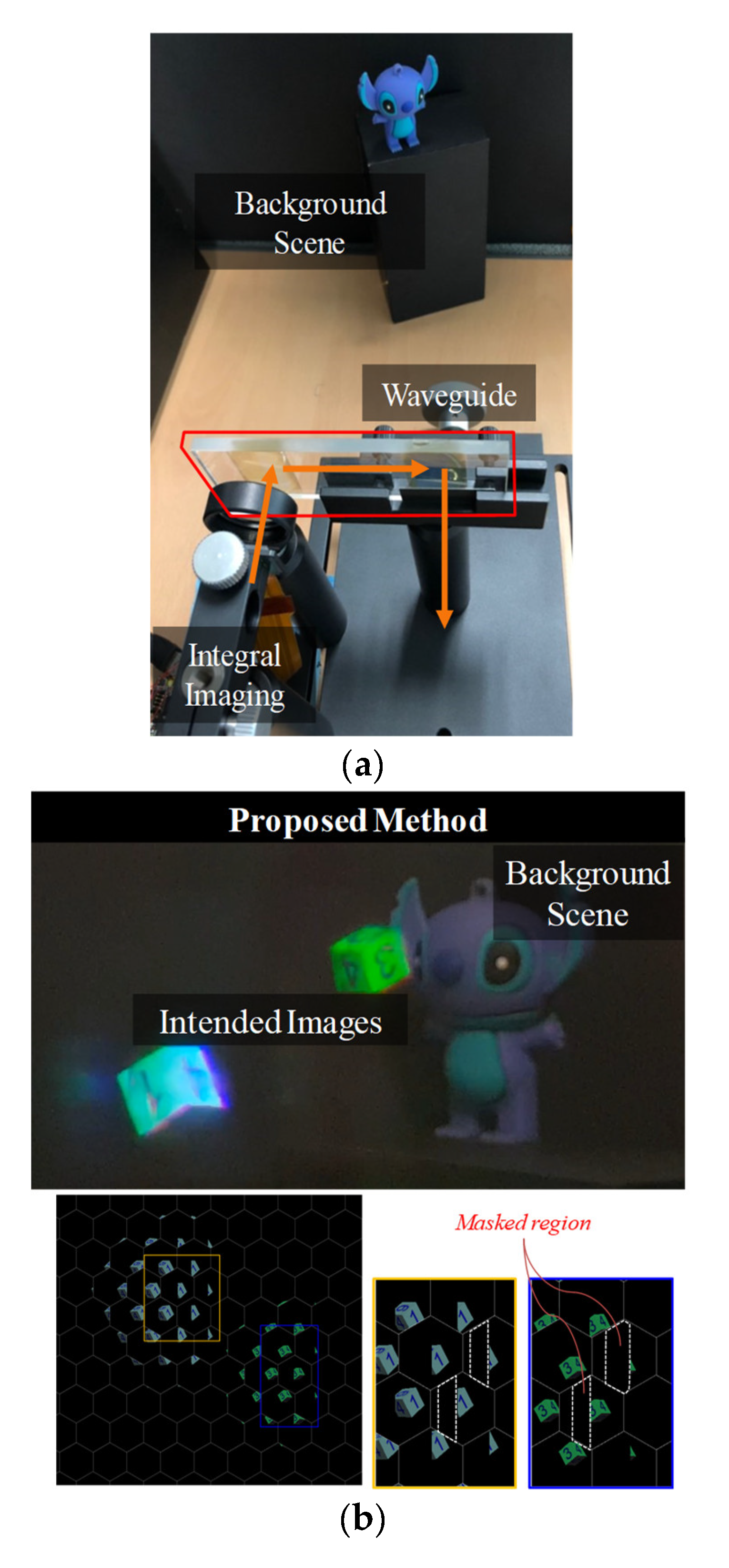
3.1. Fabrication of Full-Color Holographic Waveguide
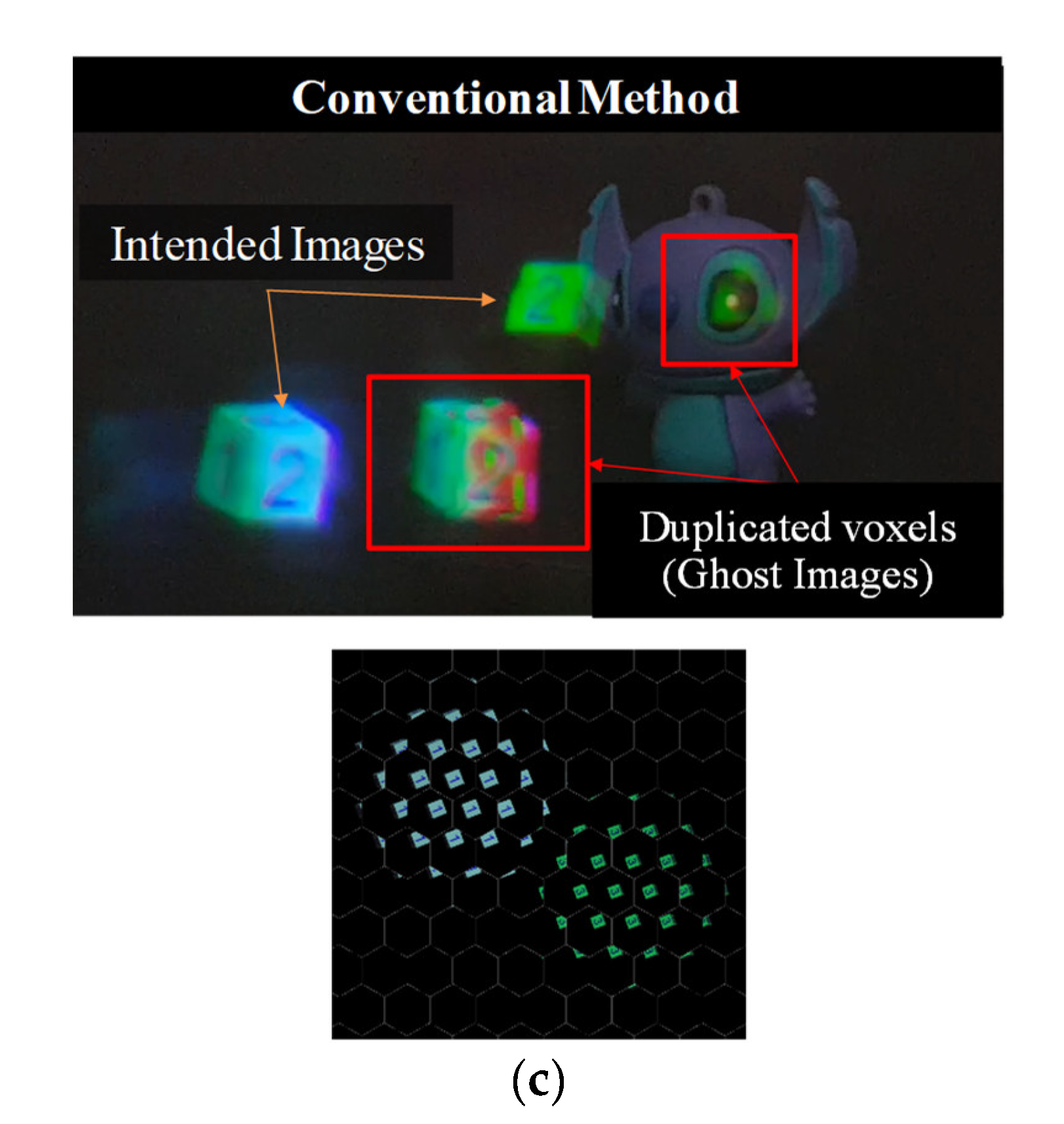
3.2. Displaying Experiments for Representing Voxels
4. Discussion
5. Conclusions
Author Contributions
Funding
Informed Consent Statement
Data Availability Statement
Conflicts of Interest
References
- Cakmakci, O.; Rolland, J. Head-worn displays: A review. J. Disp. Technol. 2006, 2, 199–216. [Google Scholar] [CrossRef]
- Zhang, Y.; Fang, F. Development of planar diffractive waveguides in optical see-through head-mounted displays. Precis. Eng. 2019, 60, 482–496. [Google Scholar] [CrossRef]
- Hua, H.; Hu, X.; Gao, C. A high-resolution optical see-through head-mounted display with eyetracking capability. Opt. Express 2013, 21, 30993–30998. [Google Scholar] [CrossRef]
- Yoo, C.; Chae, M.; Moon, S.; Lee, B. Retinal projection type lightguide-based near-eye display with switchable viewpoints. Opt. Express 2020, 28, 3116–3135. [Google Scholar] [CrossRef] [PubMed]
- Jang, C.; Bang, K.; Moon, S.; Kim, J.; Lee, S.; Lee, B. Retinal 3D: Augmented reality near-eye display via pupil-tracked light field projection on retina. ACM Trans. Graph. 2017, 36, 1–13. [Google Scholar] [CrossRef]
- Cheng, D.; Wang, Y.; Xu, C.; Song, W.; Jin, G. Design of an ultra-thin near-eye display with geometrical waveguide and freeform optics. Opt. Express 2014, 22, 20705–20719. [Google Scholar] [CrossRef] [PubMed]
- Zhang, W.; Wang, Z.; Xu, J. Research on a surface-relief optical waveguide augmented reality display device. Appl. Opt. 2018, 57, 3720–3729. [Google Scholar] [CrossRef] [PubMed]
- Xu, M.; Hua, H. Methods of optimizing and evaluating geometrical lightguides with microstructure mirrors for augmented reality display. Opt. Express 2019, 27, 5523–5543. [Google Scholar] [CrossRef] [Green Version]
- Kress, B.C.; Cummings, W.J. Optical Architecture of Hololens Mixed Reality Headset; SPIE: Brussels, Belgium, 2017; Volume 10335, p. 103350K. [Google Scholar]
- Piao, M.-L.; Kim, N. Achieving high levels of color uniformity and optical efficiency for a wedge-shaped waveguide headmounted display using a photopolymer. Appl. Opt. 2014, 53, 2180–2186. [Google Scholar] [CrossRef]
- Shishova, M.; Zherdev, A.; Lushnikov, D.; Odinokov, S. Recording of the multiplexed Bragg diffraction gratings for waveguides using phase mask. Photonics 2020, 7, 97. [Google Scholar] [CrossRef]
- Yoshida, T.; Tokuyama, K.; Takai, Y.; Tsukuda, D.; Kaneko, T.; Suzuki, N.; Anzai, T.; Yoshikaie, A.; Akutsu, K.; Machida, A. A plastic holographic waveguide combiner for light-weight and highly-transparent augmented reality glasses. J. Soc. Inf. Disp. 2018, 26, 280–286. [Google Scholar] [CrossRef]
- Su, W.-C.; Zhou, S.-K.; Lin, B.-S.; Lin, W.-K. Simplified Aberration Analysis Method of Holographic Waveguide Combiner. Photonics 2020, 7, 71. [Google Scholar] [CrossRef]
- Yeom, H.-J.; Kim, H.-J.; Kim, S.-B.; Zhang, H.; Li, B.; Ji, Y.-M.; Kim, S.-H.; Park, J.-H. 3D holographic head mounted display using holographic optical elements with astigmatism aberration compensation. Opt. Express 2015, 23, 32025–32034. [Google Scholar] [CrossRef] [PubMed]
- Lin, W.-K.; Matoba, O.; Lin, B.-S.; Su, W.-C. Astigmatism and deformation correction for a holographic head-mounted display with a wedge-shaped holographic waveguide. Appl. Opt. 2018, 57, 7094–7101. [Google Scholar] [CrossRef] [PubMed]
- Chang, C.; Bang, K.; Wetzstein, G.; Lee, B.; Gao, L. Toward the next-generation VR/AR optics: A review of holographic near-eye displays from a human-centric perspective. Optica 2020, 7, 1563–1578. [Google Scholar] [CrossRef]
- Shen, Z.; Zhang, Y.; Weng, Y.; Li, X. Characterization and optimization of field of view in a holographic waveguide display. IEEE Photonics J. 2017, 9, 1–11. [Google Scholar] [CrossRef]
- Lee, C.-K.; Lee, T.; Sung, H.; Min, S.-W. Analysis and design of wedge projection display system based on ray retracing method. Appl. Opt. 2013, 52, 3964–3976. [Google Scholar] [CrossRef]
- Park, J.-H.; Hong, K.; Lee, B. Recent progress in three-dimensional information processing based on integral imaging. Appl. Opt. 2009, 48, H77–H94. [Google Scholar] [CrossRef]
- Park., S.; Yeom., J.; Jeong, Y.; Chen, N.; Hong, J.-Y.; Lee, B. Recent issues on integral imaging and its applications. J. Inf. Disp. 2014, 15, 37–46. [Google Scholar] [CrossRef]
- Kim, Y.; Kim, J.; Hong, K.; Yang, H.K.; Jung, J.-H.; Choi, H.; Min, S.-W.; Seo, J.-M.; Hwang, J.-M.; Lee, B. Accommodative response of integral imaging in near distance. J. Disp. Technol. 2012, 8, 70–78. [Google Scholar] [CrossRef]
- Chen, C.; Deng, H.; Zhong, F.-Y.; Ji, Q.-L.; Li, Q. Effect of viewpoints on the accommodation response in integral imaging 3D display. IEEE Photonics J. 2020, 12, 7000414. [Google Scholar] [CrossRef]
- Chen, N.; Yeom, J.; Jung, J.H.; Park, J.H.; Lee, B. Resolution comparison between integral-imaging-based hologram synthesis methods using rectangular and hexagonal lens arrays. Opt. Express 2011, 19, 26917–26927. [Google Scholar] [CrossRef] [PubMed]
- Wen, J.; Yan, X.; Jiang, X.; Yan, Z.; Wang, Z.; Chen, S.; Lin, M. Comparative study on light modulation characteristic between hexagonal and rectangular arranged macro lens array for integral imaging based light field display. Opt. Commun. 2020, 466, 125613. [Google Scholar] [CrossRef]
- Yeom, J.; Son, Y.; Choi, K.-S. Pre-compensation method for optimizing recording process of holographic optical element lenses with spherical wave reconstruction. Opt. Express 2020, 28, 33318–33333. [Google Scholar] [CrossRef]
- Hong, J.; Yeom, J.; Lee, B. Enhancing angular sampling rate of integral floating display using dynamically variable apertures. Opt. Express 2012, 20, 10242–10255. [Google Scholar] [CrossRef]
- Luo, C.-G.; Xiao, X.; Martínez-Corral, M.; Chen, C.-W.; Javidi, B.; Wang, Q.-H. Analysis of the depth of field of integral imaging displays based on wave optics. Opt. Express 2013, 21, 31263–31273. [Google Scholar] [CrossRef] [Green Version]
- Shin, D.; Kim, C.; Koo, G.; Won, W.H. Depth plane adaptive integral imaging system using a vari-focal liquid lens array for realizing augmented reality. Opt. Express 2020, 28, 5602–5616. [Google Scholar] [CrossRef]
- Huang, H.; Hua, H. High-performance integral-imaging-based light field augmented reality display using freeform optics. Opt. Express 2018, 26, 17578–17590. [Google Scholar] [CrossRef] [Green Version]


| Items | Specifications | |
|---|---|---|
| Waveguide | Dimension | 105.0 mm × 34.0 mm × 5.0 mm |
| Material | BK7 | |
| HOEs | Dosage | 31.0 mJ/cm2 (460 nm) 21.4 mJ/cm2 (532 nm) 17.2 mJ/cm2 (640 nm) |
| DE 1 (in-coupler) | 72.3% (460 nm) 78.0% (532 nm) 72.0% (640 nm) | |
| DE (out-coupler) | 73.3% (460 nm) 75.1% (532 nm) 72.9% (640 nm) | |
| Size | 25.0 mm × 16.0 mm | |
| Distance between in-coupler and out-coupler | 62.5 mm | |
| Thickness | 0.36 mm | |
| Items | Specifications | |
|---|---|---|
| Micro-display | Resolution | 1920 × 1080 |
| Pixel pitch | 8.3 μm | |
| Size | 15.8 mm × 8.99 mm | |
| Lenslet-array (Hexagonal) | Pitch | 1 mm |
| Focal length | 3 mm | |
| Relay Lens | Diameter | 1 inch |
| Focal length | 30 mm | |
| Method | Display Source | Color | Voxel Representation |
|---|---|---|---|
| Proposed method | OLED + lenslet-array (Broad-band source) | Full-color | Supported |
| Virtual images at optical infinity (Refs. [10,12]) | Flat-panel display + Collimation optics (Broad-band source) | Full-color | Not supported |
| Holographic display (Refs. [14,15]) | Phase modulator + Collimated laser | Monochrome | Supported |
Publisher’s Note: MDPI stays neutral with regard to jurisdictional claims in published maps and institutional affiliations. |
© 2021 by the authors. Licensee MDPI, Basel, Switzerland. This article is an open access article distributed under the terms and conditions of the Creative Commons Attribution (CC BY) license (https://creativecommons.org/licenses/by/4.0/).
Share and Cite
Yeom, J.; Son, Y.; Choi, K. Crosstalk Reduction in Voxels for a See-Through Holographic Waveguide by Using Integral Imaging with Compensated Elemental Images. Photonics 2021, 8, 217. https://doi.org/10.3390/photonics8060217
Yeom J, Son Y, Choi K. Crosstalk Reduction in Voxels for a See-Through Holographic Waveguide by Using Integral Imaging with Compensated Elemental Images. Photonics. 2021; 8(6):217. https://doi.org/10.3390/photonics8060217
Chicago/Turabian StyleYeom, Jiwoon, Yeseul Son, and Kwangsoon Choi. 2021. "Crosstalk Reduction in Voxels for a See-Through Holographic Waveguide by Using Integral Imaging with Compensated Elemental Images" Photonics 8, no. 6: 217. https://doi.org/10.3390/photonics8060217